DOI:
10.1039/D1RA07876C
(Paper)
RSC Adv., 2021,
11, 39672-39679
First-principles insights onto structural, electronic and optical properties of Janus monolayers CrXO (X = S, Se, Te)
Received
26th October 2021
, Accepted 7th December 2021
First published on 13th December 2021
Abstract
The lacking of the vertical mirror symmetry in Janus structures compared to their conventional metal monochalcogenides/dichalcogenides leads to their characteristic properties, which are predicted to play significant roles for various promising applications. In this framework, we systematically examine the structural, mechanical, electronic, and optical properties of the two-dimensional 2H Janus CrXO (X = S, Se, Te) monolayers by using first-principles calculation method based on density functional theory. The obtained results from optimization, phonon spectra, and elastic constants demonstrate that all three Janus monolayers present good structural and mechanical stabilities. The calculated elastic constants also indicate that the Janus CrTeO monolayer is much mechanically flexible than the other two monolayers due to its low Young's modulus value. The metallic behavior is observed at the ground state for the Janus CrSeO and CrTeO monolayers in both PBE and HSE06 levels. Meanwhile, the Janus CrSO monolayer exhibits a low indirect semiconducting characteristic. The bandgap of CrSO after the correction of HSE06 hybrid functional is the average value of its binary transition metal dichalcogenides. The broad absorption spectrum of CrSO reveals the wide activated range from the visible to near-ultraviolet region. Our findings not only present insight into the brand-new Janus CrXO monolayers but can also motivate experimental research for several applications in optoelectric and nanoelectromechanical devices.
1 Introduction
Two-dimensional (2D) layered-nanomaterials along with graphene1 are strongly investigated both theoretically and experimentally2–6 due to their outstanding properties which meet the demands of future applications. The large-scale research turned to search alternate 2D materials including graphene-like structures when shortcomings of graphene emerged. Consequently, a series of 2D nanomaterials have been reported, such as phosphorene,7,8 Xene (stanene,9 silicene10 or germanene),11,12 hexagonal boron nitride (h-BN),13 transition metal chalcogenides (TMDs)14,15 and so forth. They possess many superior mechanical, electronic, and photocatalytic properties which do not exist in 2D forms.16–20 Among the 2D materials mentioned above, the layered TMDs have attracted considerable interest due to their unique structure, extraordinary physical properties, and the wide potential applications such as catalysis,21 optoelectronics and spintronics,22 electrochemical energy storage,23 nanoelectronics.24 Although, there are several significant successes and unprecedented efforts which consequence upon various beyond-graphene 2D systems, the complete potentials of such systems are still unexplored which may restrict their usage in devices.
Recently, Janus 2D materials have been considerably interested in as a brand-new class of 2D layered-nanomaterials.25–29 Owing to the lacking of the vertical symmetry, Janus materials possess asymmetric structures resulting in many new electronic and photocatalytic properties with considerable promising applications such as in energy storage and nanoelectronic technologies.30–32 The Janus 2D material reported originally in 2009,33 named graphone, was a graphene-based material obtained by hydrogenating only one side of graphene. Since then, many experimental and theoretical studies have released diverse Janus structures dominantly based on their binary or ternary TMDs.34,35 Therefore, this work is carried out with motivation to firstly simulate the 2D Janus CrXO (X = S, Se, Te) monolayers that can be built from commonly reported transition metal dichalcogenides or oxide CrX2 or CrO2. The TMD monolayers possess the rich chemical diversity and multiple phases of crystalline structures such as octahedral (1T), hexagonal (2H), and distorted octahedral (1T′) structures36,37 depending on the arrangements of the Cr and chalcogens atoms. Among the three major structures, the semiconducting 2D CrX2 monolayers with 2H-phases are much interested in due to their more energetically stable forms.38 The 2H-phases of Cr dichalcogenides are direct gap semiconductors, whereas its oxide has an indirect energy gap. Particularly, 2H monolayers CrO2, CrS2, CrSe2 and CrTe2 were previously found to be non-magnetic materials.39,40 As for the phonon bandgap, which separates the acoustic vibrational branches from the six optical ones, all of the 2H-phases of Cr dichalcogenides and oxide monolayers are found to be absent resulting in the reduction of thermal conductivity. The 2H-CrO2 has the largest phonon thermal conductance at all temperatures since it composed of the lightest atoms in the group. Together with the increase in temperature, the thermal conductance of CrO2 increases significantly.41 However, the structural symmetry along the out-of-plane direction limits the applications of those TMD monolayers. The asymmetric Janus CrXO monolayers not only inherits the advantages of 2H-phases Cr dichalcogenides but also play a key role to control optical and electronic properties which are the crucial deciding factor for various practical applications.
In the present work, by means of first-principles calculation based on DFT, we report the first theoretical investigation on the 2D Janus CrXO monolayers. The current paper is organized as follows: in Section 2, we describe the computational methodologies. Then in Section 3, we discuss the optimized structural parameters and dynamical stability via the phonon spectra examination, followed by the discussion of mechanical stability via elastic constants survey. The electronic properties are investigated by analyzing the band structures. Since this is the first theoretical and experimental research, our obtained result can provide effective guidance for fabrication, as well as application of the 2D Janus CrXO monolayers in future optoelectronic and nanoelectronic devices.
2 Computational methods
All simulations in this study were performed by the DFT method as implemented in the Quantum Espresso code.42 We used the project augmented wave (PAW) method to consider the valence electron–ion core interactions.43 The generalized gradient approximations (GGA) by the Perdew–Burke–Ernzerhof (PBE) were used to treat the correlation and exchange functionals. The spin–orbit coupling (SOC) was taken into account in self-consistent investigation for electronic characteristics of Janus monolayers.44 Further, the hybrid functional by Heyd–Scuseria–Ernzerhof (HSE06)45 was also used to correct the band structures of the investigated monolayers. The DFT-D2 method by Grimme46 was also used to correct the van der Waals interactions in the layered materials. The cut-off energy for the plane-wave basis was adopted as 500 eV. A (15 × 15 × 1) k-mesh was built by the Monkhorst–Pack method to sample the Brillouin zone. The atomic structures of systems were fully optimized until the residual forces on atoms were less than 10−3 eV Å−1. We inserted a vertical vacuum space of 20 Å to reduce the interactions between neighbor slabs. Phonon spectra of monolayers were evaluated by the density functional perturbation theory (DFPT) method.47 The Born–Huang's criteria were used to evaluate the mechanical stability of monolayers.
3 Results and discussion
3.1 Geometry and stability
The CrXO (X = S, Se, Te) monolayers can be constructed from CrX2 or CrO2. However, CrO2 is unstable at room temperature.48 It is known that CrX2 stably exists in 2H.40,49 Hence, the 2H Janus CrXO monolayers can be formed based on 2H CrX2 by replacing the bottom layer of X with O atoms. The most stable 2H structures (have the lowest energies) of the Janus CrXO (X = S, Se, Te) are optimized and sketched in Fig. 1. It can be seen that Janus CrXO consists of three layers of atoms, namely, X, Cr, and O atoms from the top to the bottom. The optimized in-plane hexagonal unit cell lattice constants a of three structures and the vertical distance between the oxygen or chalcogen atoms Δh are listed in Table 1. Both a and Δh values are increasing from CrSO to CrTeO, although the discrepancies are quite small, less than 5%. It is noteworthy that the breaking of the mirror symmetry in the original structure leads to a vertical asymmetry in the Janus CrXO which is evident in the large difference (about 12%) in the bond lengths of Cr–O (dCr–O) and Cr–X (dCr–O). The calculated Cr–O (dCr–O) bond lengths are similar for all three structures, while those of Cr–X (dCr–O) are quite different, i.e., the shortest one is found for Cr–S (2.26 Å), followed by Cr–Se (2.42 Å), the longest one is found for Cr–Te (2.75 Å). These obtained results can be attributed to the dissimilarity in ionic radii of S (1.84 Å), Se (1.98 Å) and Te (2.21 Å). Note that the free-standing Janus structures may be more stable in the curled forms due to their asymmetry.50 This observation is consistent with previous predictions that sheets tend to curve in response to lattice-mismatch in its structure.51 In the present study, bending curvature is not included in our calculations.
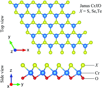 |
| | Fig. 1 Different views of optimized atomic structures of Janus CrXO (X = S, Se, Te) monolayers. | |
Table 1 Calculate the lattice constant a, bond length d, thickness Δh, and bond angle ϕ of the Janus CrXO monolayers (X = S, Se, Te)
| |
a (Å) |
dCr–O (Å) |
dCr–X (Å) |
Δh (Å) |
ϕ∠XCrX (deg) |
ϕ∠OCrO (deg) |
ϕ∠XCrO (deg) |
| CrSO |
2.83 |
1.95 |
2.26 |
2.63 |
77.67 |
92.85 |
76.85 |
| CrSeO |
2.94 |
1.96 |
2.42 |
2.70 |
74.55 |
97.25 |
75.57 |
| CrTeO |
3.09 |
1.94 |
2.75 |
2.86 |
68.06 |
105.72 |
72.74 |
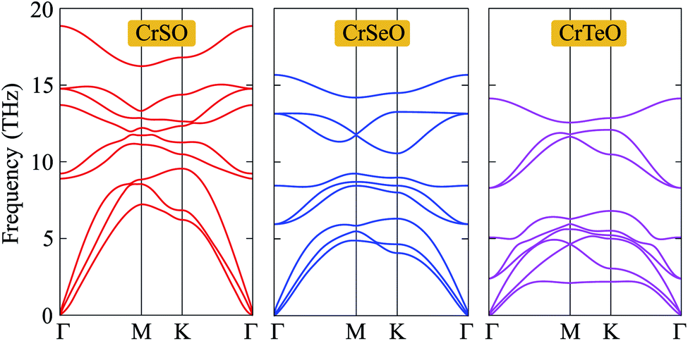
Next, in order to test the dynamical stability of the Janus CrXO, the phonon dispersion curves along several lines of high symmetry presented in Fig. 2 are analyzed. The frequency and phonon dispersion bands of all three monolayers are not quite different from each other. It is found that these three systems of the Janus CrXO are dynamically stable since there are no imaginary modes in the whole Brillouin zones. As depicted in Fig. 2, the phonon dispersion curves of the Janus CrXO monolayers have 9 vibrational branches, including 3 acoustic branches with low frequencies and 6 optical branches with higher frequencies. There is no gap between optical and acoustic branches resulting in the robust optical-acoustic scattering in CrXO monolayers, and hence, thermal conductivity may be affected. At the Γ point, optical phonons include non-degenerate vibrational modes for CrSO, while for CrSeO and CrTeO, doubly-degenerate vibration modes are found. The reduction in the vibration frequencies and the falling into the lower energy region of the optical branches are found from CrSO to CrTeO. The acoustic bands are also shifted towards low frequencies and specifically are confined in a narrow frequency range. This trend can be attributed to the atomic mass. Since CrSO monolayer has the lowest atomic mass, the vibrational frequencies of CrSO are higher compared to others. The less dispersive acoustic modes, and hence lower group velocity, are observed due to the downward shift of the acoustic branches. Moreover, for the acoustic branches, the lowering of the steepness is the result of weak bonding that is attributed to the increasing Cr–X bond lengths when moving down on a chalcogen atom. This agrees with the previous optimized results.
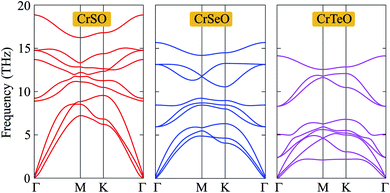 |
| | Fig. 2 Phonon dispersion curves of the Janus CrXO monolayers. | |
For more argument of the Janus CrXO monolayers' mechanical strength, which is essential for their applications, elastic constants (Cij), Young's modulus (Y2D) and Poisson's ratio (ν) are examined. Young's modulus is a parameter representing the stiffness of a solid, evaluates the material resistance to elastic (recoverable) deformation under load. The Young's modulus is given by Y2D = (C112 − C122)/C11. Poisson's ratio (ν = C12/C11) is defined as the ratio of the relative contraction strain normal to the applied force to the relative extension strain in the force direction. These two key factors are calculated and depicted in Fig. 3. In this figure, we show the dependence of Y2D and ν on the direction of three monolayers. The circular features of Y2D and ν in the polar diagram indicate the fully elastic isotropy of the CrXO monolayers. For comparison, the values of Cij, Y2D and ν are listed in Table 2. It is noticed that all the calculated elastic constants (Cij) are positive. It is demonstrated that all three monolayers obey the mechanical stability constraints, namely C11 > C12, C11 + 2C12 > 0, and C66 > 0.52 We obtained the decreasing values of Y2D in order of CrSO > CrSeO > CrTeO. This means monolayer CrTeO is the easiest one to deform under in-plane external force, followed by CrSeO and CrSO. It is reasonable and in good agreement with the previous analysis in Section 1 since the Cr–Te bonds are the longest and deformable compared to those of Cr–Se and Cr–O. In contrast to the values of Y2D, those of ν are increasing from CrSO to CrTeO. Besides, the calculated Poisson's ratio values are all positive demonstrating the tendency of expansion (contraction) in the perpendicular direction when a compressive strain (tensile) is acted in one direction. One can use the ν to evaluate the ductile–brittle behaviors.53 Our calculated results indicate that CrSO monolayer is brittle with ν < 0.31, while CrSeO and CrTeO monolayers with ν > 0.31 are ductile, where CrTeO is much more ductile with ν = 0.80 (about 80% higher compared to that of CrSeO). The obtained results for both Young's modulus (Y2D) and Poisson's ratio (ν) are in good accordance with each other.
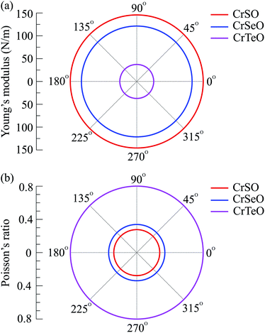 |
| | Fig. 3 Polar diagram for the Young's modulus (a) and Poisson's ratio (b) of CrXO monolayers (X = S, Se, Te). | |
Table 2 Elastic constant Cij, Young's modulus Y2D, Poisson's ratio of the Janus CrXO monolayers (X = S, Se, Te)
| |
C11 (N m−1) |
C12 (N m−1) |
C66 (N m−1) |
Y2D (N m−1) |
ν |
| CrSO |
157.86 |
43.71 |
57.08 |
145.76 |
0.28 |
| CrSeO |
137.12 |
46.46 |
45.33 |
121.38 |
0.34 |
| CrTeO |
103.88 |
83.17 |
10.35 |
37.28 |
0.80 |
3.2 Electronic structures
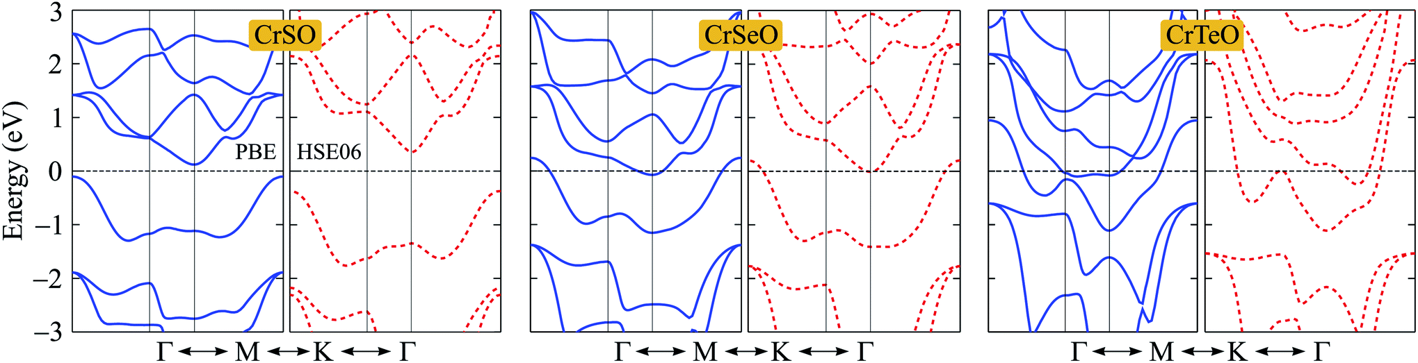
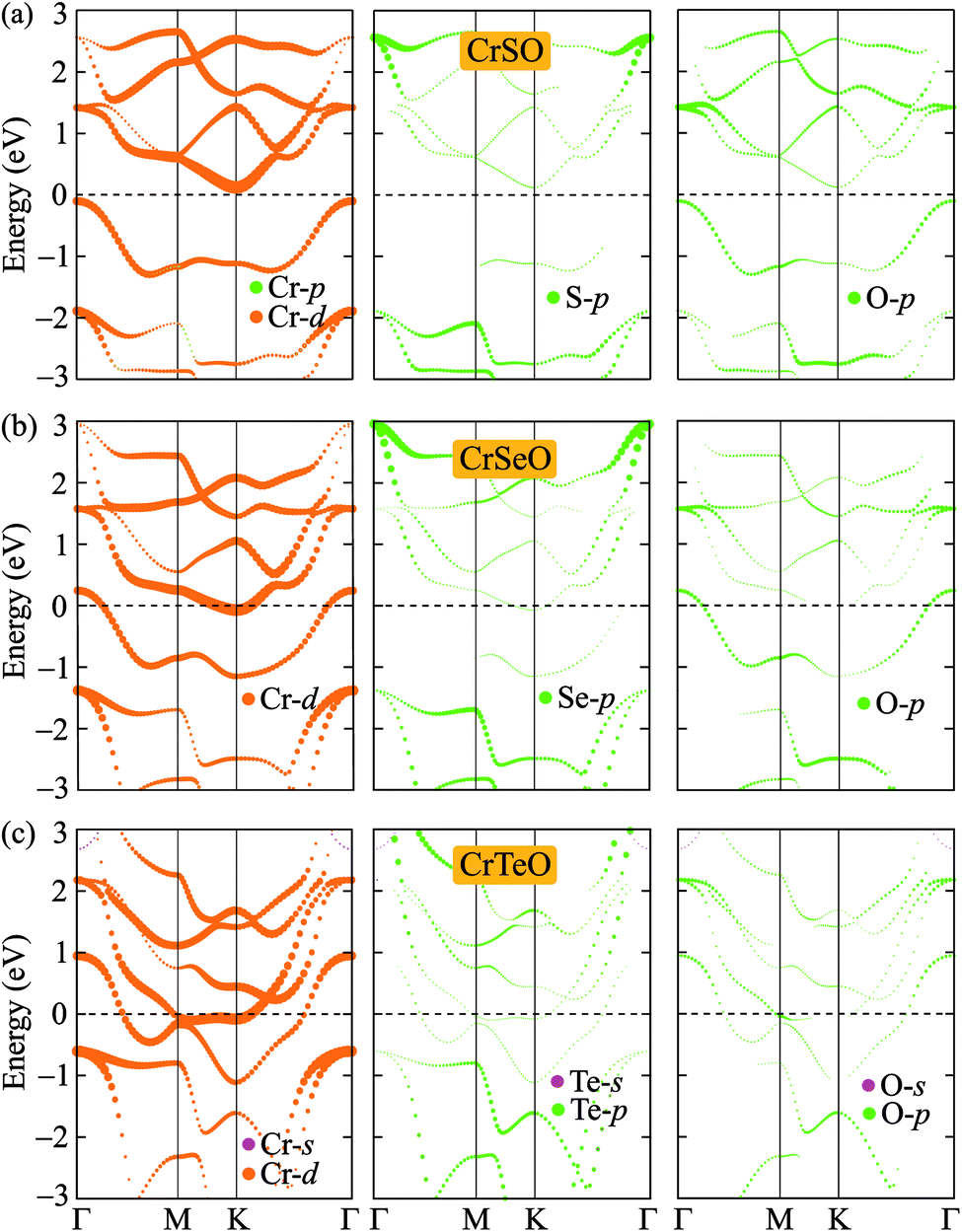
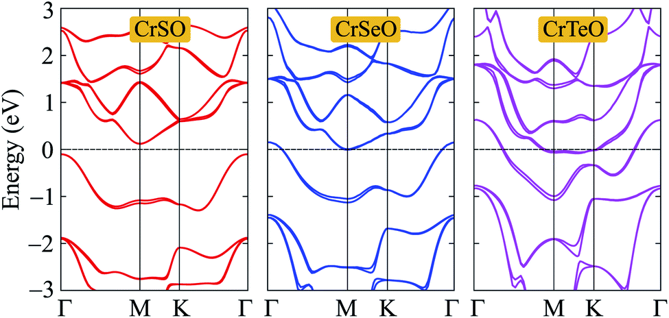
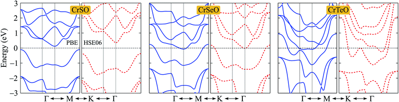
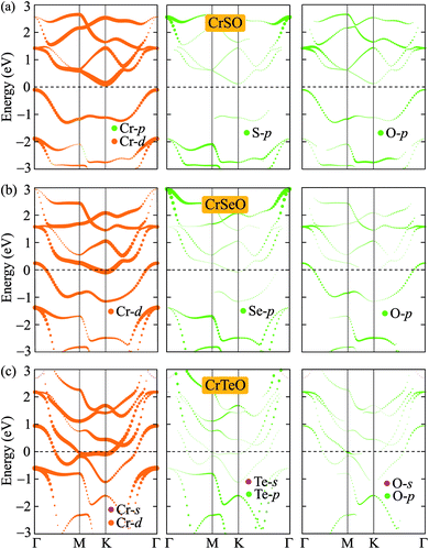
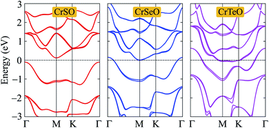
After proving that the Janus CrXO monolayers studies here are dynamically stable, we use both PBE and HSE06 functionals in order to examine precisely the variation of electronic properties of all three systems and confirm our calculations. We calculate the electronic structure of these systems along the Γ–M–K–Γ direction in the energy intervals −3 eV to 3 eV. Our calculations demonstrate that all three structures of CrXO are non-magnetic materials. Previously, CrO2, CrS2, CrSe2 and CrTe2 monolayers were reported to be non-magnetic semiconductors.39,40 The energy band structures plotted in Fig. 4 present the same profiles for three monolayers by both PBE and HSE06 functional. Unlike their binary counterparts, the Janus CrSeO and CrTeO monolayers become metallic at both PBE and HSE06 levels. Meanwhile, CrSO monolayer is low indirect semiconductor with bandgap of EgPBE = 0.22 eV and EgHSE06 = 0.72 eV at the PBE and HSE06 levels, respectively (Table 3), and its conduction band minimum (CBM) and valence band maximum (VBM) points reside at the K and Γ points at the equilibrium state. The significant enlargement (more than three times) of the calculated bandgap by HSE06 compared to PBE is observed and can be attributed to the underestimation the bandgap problem of semiconductors and insulators by PBE functional. To get a better insight into the electronic characteristics of the three materials, the weighted bands are also examined (Fig. 5). From the plotted weighted bands, it can be estimated the contributions of each atomic orbitals to the VBM/CBM. It is found that both VBM and CBM of the band structures of CrSO are constituted due to Cr-d orbitals.
 |
| | Fig. 4 Band structures of CrXO (X = S, Se, Te) monolayers at the PBE (solid lines) and HSE06 (dashed lines) levels. | |
Table 3 Evaluated bandgaps Eg using the PBE, PBE+SOC, and HSE06 functionals, Fermi level EF, vacuum level difference ΔΦ, and work functions ΦX and ΦO on two different sides of the Janus CrXO monolayers. M stands for metallic characteristic
| |
EgPBE (eV) |
EgPBE+SOC (eV) |
EgHSE06 (eV) |
EF (eV) |
ΔΦ (eV) |
Φ1 (eV) |
Φ2 (eV) |
| CrSO |
0.22 |
0.21 |
0.72 |
−3.28 |
2.53 |
7.07 |
4.54 |
| CrSeO |
M |
M |
M |
−2.78 |
2.52 |
6.55 |
4.03 |
| CrTeO |
M |
M |
M |
−1.44 |
1.60 |
5.22 |
3.62 |
 |
| | Fig. 5 Weighted band structures of (a) CrSO, (b) CrSeO, and (c) CrTeO monolayers. | |
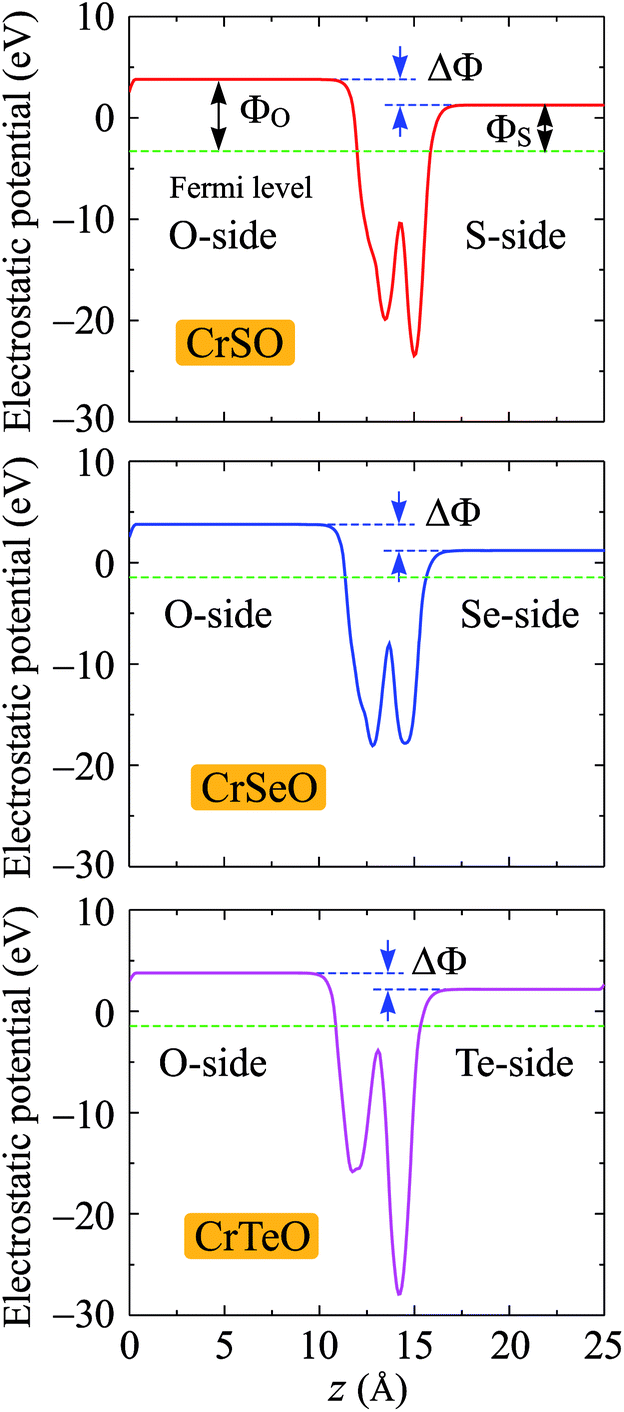
Due to the vertical asymmetry, there is an intrinsic built-in electric field available in the Janus structures.54 Hence, there is a difference in vacuum levels between two different sides of the Janus structure. Therefore, the dipole correction55 is used in the calculations for the electrostatic potential as shown in Fig. 6. Fermi level EF, vacuum level difference ΔΦ, and work functions ΦX and ΦO on two different sides of the Janus CrXO monolayers are calculated to evaluate the electron's ability to escape from the material surfaces (Table 3). Since the electronegativities of the X and O atoms are different, a finite out-of-plane dipole moment is appeared owing to the transfer of charges across the metal. The shifting in the vacuum level on the two sides of the monolayer observed in Fig. 6 can be used to evaluate the size of this dipole. It is worth noting that the vacuum level will be different due to the dipole-induced potential step. The Fermi levels shift up from −3.28 eV to −2.78 eV, and −1.44 eV with increasing the atomic number from S to Te, leading to the shifting of d-band away from the Fermi level, which also causes the most depletion in the band structure close to the Fermi level of CrTeO monolayer, followed by that of CrSeO monolayer. This can result in the transition to metallic properties of Janus CrSeO and CrTeO monolayers from the direct semiconducting natures of their counterparts, which is in good agreement with the electronic band structure observation. Due to the lacking of the vertical symmetry, the work functions ΦX and ΦO are different on two sides. For CrSO and CrSeO monolayers, the difference of work function on two sides, ΔΦ, are similar (about 2.5 eV) and 0.9 eV higher than that in CrTeO monolayer. This discrepancy could be due to the larger electronegativity of the S and Se atoms compare to that of Te.
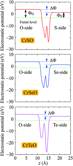 |
| | Fig. 6 Planar average electrostatic potential of CrXO (X = S, Se, Te). The horizontal dashed line refers to the Fermi. ΔΦ is the vacuum level difference in the vacuum between two sides. | |
It is well-known that the SOC effect plays an important in the electronic characteristics of 2D nanomaterials, especially compounds based on heavily elements. In the present study, we also calculate the band structures of CrXO monolayer by using the PBE+SOC method to evaluate the influence of the SOC effect on their electronic properties. The PBE+SOC band structures of CrXO monolayers are depicted in Fig. 7. Our calculated results demonstrate that there are band splitting in the band structures of CrXO when the SOC is included, especially in compounds containing heavy components such as CrSeO and CrTeO. The metallic properties of both CrSeO and CrTeO monolayers are preserved and the band gap of CrSO does not change when the SOC effect was taken into account. The unchanging band gap of CrSO monolayer can be explained that there is no too heavy elements in the CrSO compound.
 |
| | Fig. 7 Calculated band structures of CrXO monolayers by the PBE+SOC method. | |
3.3 Optical properties
Insight into the optical properties of a compound is essential and significant for many applications and applied research. Due to the metallic characteristics of CrSeO and CrTeO monolayers, hence, we only investigate the optical properties of the Janus CrSO by focusing on the complex dielectric function ε(ω) and the adsorption coefficient A(ω). The ε(ω) is one of the crucial parameters of materials in optoelectronic and photovoltaic applications and is defined as ε(ω) = ε1(ω) + iε2(ω), where ε1(ω) and ε2(ω) are the real and the imaginary parts of the complex dielectric function. The real part of dielectric function ε1(ω) can be calculated based on Kramers–Kronig relation56,57 which represents the electronic polarization under the incident light and the imaginary part ε2(ω) could be obtained from the momentum matrix elements between the occupied and unoccupied wave functions and describes all the transitions from VB to CB:56,57| |
 | (1) |
where V is the unit cell volume; ω and p are the incoming photon angular frequency and momentum operator, respectively; |knσ〉 and fkn stand for the crystal wave-function and Fermi distribution function, respectively; e and m are the elementary charge and electron mass, respectively. The summations refer to the first Brillouin zone wave vectors.
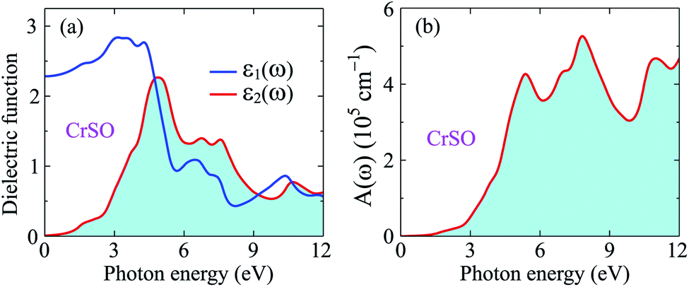
Fig. 8(a) illustrates the evaluated real part (blue line) and imaginary part (red line) of the complex ε(ω) for the Janus CrSO monolayer as a function of incoming photon energy up to 12 eV. As depicted in Fig. 8(a), ε1(ω) increases with increasing photon energy at low energy regime, passing through a broad peak of about 3 eV. Besides, further increase in the energy of photons leads to a lowering value of ε1(ω). The imaginary part is positive indicating that light can propagate in this range from 0 eV to 12 eV. The static dielectric constant ε1(0) is found to be about 2.3 eV.
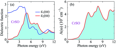 |
| | Fig. 8 Dielectric function (a) and absorption coefficient (b) of CrSO monolayer. | |
Based on the complex ε(ω), the absorption coefficient A(ω) is computed for further analysis of the optical properties and can be defined as57,58
| |
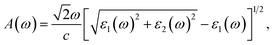 | (2) |
where
c refers to the light speed in vacuum.
From Fig. 8(b), we can see that the optical gap of the Janus CrSO monolayer is deduced to be about 0.7 eV. This optical gap agrees well with the previous bandgap by using HSE06 functional. The Janus CrSO monolayer has a wide absorption spectrum. It has good optical absorption in both the visible and ultraviolet regions. The first absorption peak is in the near-ultraviolet region, at 5.37 eV. CrSO has the strongest light absorption in the near-ultraviolet region and maximum absorbance up to 5.26 × 105 cm−1 at the incoming photon energy of 7.82 eV. With a wide absorption spectrum and high absorption coefficient, CrSO can be a potential material for applications in optoelectronics.
4 Conclusion
In conclusion, we systematically considered the structural, mechanical, electronic, and optical properties of the 2D Janus CrXO monolayers by means of first-principles study. These three systems are constructed from 2H-phases counterparts Cr dichalcogenides or oxide. The optimized geometry configurations are obtained. The mechanical stabilities of Janus CrXO monolayers are demonstrated by phonon spectrum analysis in which the shift to lower frequencies are found for both optical and acoustic branches of three Janus monolayers. The stability of the Janus CrXO monolayers is verified by the satisfaction of the criteria for mechanical stability. The electronic structure analysis indicates that while the CrSeO and CrTeO monolayers are metallic, the CrSO monolayer is a low indirect semiconductor, at both PBE and HSE06 levels. We demonstrate the shift of metal d-band determines the electronic character of metal or semiconductor. Subsequently, the CrSO semiconductor has absorption in the visible and ultraviolet regions. Our results revealed the Janus CrXO (X = S, Se, Te) monolayers possess good properties that are potential candidates for optoelectronics and energy conversion applications.
Conflicts of interest
There are no conflicts to declare.
References
- K. S. Novoselov, A. K. Geim, S. V. Morozov, D. Jiang, Y. Zhang, S. V. Dubonos, I. V. Grigorieva and A. A. Firsov, Science, 2004, 306, 666 CrossRef CAS.
- T. Cheng, H. Lang, Z. Li, Z. Liu and Z. Liu, Phys. Chem. Chem. Phys., 2017, 19, 23942–23950 RSC.
- N. N. Hieu, H. V. Phuc, V. V. Ilyasov, N. D. Chien, N. A. Poklonski, N. V. Hieu and C. V. Nguyen, J. Appl. Phys., 2017, 122, 104301 CrossRef.
- H. T. T. Nguyen, M. M. Obeid, A. Bafekry, M. Idrees, T. V. Vu, H. V. Phuc, N. N. Hieu, L. T. Hoa, B. Amin and C. V. Nguyen, Phys. Rev. B, 2020, 102, 075414 CrossRef CAS.
- H. Li, Y. Qin, B. Ko, D. B. Trivedi, D. Hajra, M. Y. Sayyad, L. Liu, S.-H. Shim, H. Zhuang and S. Tongay, Adv. Mater., 2020, 32, 2002401 CrossRef CAS.
- L. Zhang, Z. Yang, T. Gong, R. Pan, H. Wang, Z. Guo, H. Zhang and X. Fu, J. Mater. Chem. A, 2020, 8, 8813–8830 RSC.
- E. Kovalska, J. Luxa, T. Hartman, N. Antonatos, P. Shaban, E. Oparin, M. Zhukova and Z. Sofer, Nanoscale, 2020, 12, 2638–2647 RSC.
- M. Mahdavifar, S. Shekarforoush and F. Khoeini, J. Phys. D: Appl. Phys., 2020, 54, 095108 CrossRef.
- F.-f. Zhu, W.-j. Chen, Y. Xu, C.-l. Gao, D.-d. Guan, C.-h. Liu, D. Qian, S.-C. Zhang and J.-f. Jia, Nat. Mater., 2015, 14, 1020–1025 CrossRef CAS PubMed.
- B. J. Ryan, M. P. Hanrahan, Y. Wang, U. Ramesh, C. K. A. Nyamekye, R. D. Nelson, Z. Liu, C. Huang, B. Whitehead, J. Wang, L. T. Roling, E. A. Smith, A. J. Rossini and M. G. Panthani, Chem. Mater., 2020, 32, 795–804 CrossRef CAS.
- A. Acun, L. Zhang, P. Bampoulis, M. Farmanbar, A. van Houselt, A. N. Rudenko, M. Lingenfelder, G. Brocks, B. Poelsema, M. I. Katsnelson and H. J. W. Zandvliet, J. Phys.: Condens. Matter, 2015, 27, 443002 CrossRef CAS PubMed.
- R. Chegel and S. Behzad, Sci. Rep., 2020, 10, 704 CrossRef CAS.
- J.-H. Park, X. Yang, J.-Y. Lee, M.-D. Park, S.-Y. Bae, M. Pristovsek, H. Amano and D.-S. Lee, Chem. Sci., 2021, 12, 7713–7719 RSC.
- A. T. Hoang, K. Qu, X. Chen and J.-H. Ahn, Nanoscale, 2021, 13, 615–633 RSC.
- Z. Hu, Z. Wu, C. Han, J. He, Z. Ni and W. Chen, Chem. Soc. Rev., 2018, 47, 3100–3128 RSC.
- N. D. Hien, C. V. Nguyen, N. N. Hieu, S. S. Kubakaddi, C. A. Duque, M. E. Mora-Ramos, L. Dinh, T. N. Bich and H. V. Phuc, Phys. Rev. B, 2020, 101, 045424 CrossRef.
- D. Muoi, N. N. Hieu, C. V. Nguyen, B. D. Hoi, H. V. Nguyen, N. D. Hien, N. A. Poklonski, S. S. Kubakaddi and H. V. Phuc, Phys. Rev. B, 2020, 101, 205408 CrossRef CAS.
- T. V. Vu, C. V. Nguyen, H. V. Phuc, A. A. Lavrentyev, O. Y. Khyzhun, N. V. Hieu, M. M. Obeid, D. P. Rai, H. D. Tong and N. N. Hieu, Phys. Rev. B, 2021, 103, 085422 CrossRef CAS.
- H. T. T. Nguyen, L. Dinh, T. V. Vu, L. T. Hoa, N. N. Hieu, C. V. Nguyen, H. V. Nguyen, S. S. Kubakaddi and H. V. Phuc, Phys. Rev. B, 2021, 104, 075445 CrossRef CAS.
- T. N. Bich, S. S. Kubakaddi, L. Dinh, N. N. Hieu and H. V. Phuc, Phys. Rev. B, 2021, 103, 235417 CrossRef CAS.
- K. Ren, C. Ren, Y. Luo, Y. Xu, J. Yu, W. Tang and M. Sun, Phys. Chem. Chem. Phys., 2019, 21, 9949–9956 RSC.
- W. Feng, G.-Y. Guo and Y. Yao, 2D Mater., 2016, 4, 015017 CrossRef.
- X. Huang, Z. Zeng and H. Zhang, Chem. Soc. Rev., 2013, 42, 1934–1946 RSC.
- A. A. Bukharaev, A. K. Zvezdin, A. P. Pyatakov and Y. K. Fetisov, Phys.-Usp., 2018, 61, 1175–1212 CrossRef CAS.
- H. T. T. Nguyen, V. V. Tuan, C. V. Nguyen, H. V. Phuc, H. D. Tong, S.-T. Nguyen and N. N. Hieu, Phys. Chem. Chem. Phys., 2020, 22, 11637–11643 RSC.
- Y. Cui, L. Peng, L. Sun, M. Li, X. Zhang and Y. Huang, J. Phys.: Condens. Matter, 2020, 32, 08LT01 CrossRef CAS.
- T. V. Vu, V. T. T. Vi, H. V. Phuc, A. I. Kartamyshev and N. N. Hieu, Phys. Rev. B, 2021, 104, 115410 CrossRef CAS.
- M. Yagmurcukardes and F. M. Peeters, Phys. Rev. B, 2020, 101, 155205 CrossRef CAS.
- I. Ahmad, I. Shahid, A. Ali, L. Gao and J. Cai, RSC Adv., 2021, 11, 17230 RSC.
- L. Dong, J. Lou and V. B. Shenoy, ACS Nano, 2017, 11, 8242–8248 CrossRef CAS PubMed.
- N. N. Som and P. K. Jha, Int. J. Hydrogen Energy, 2019, 45, 23920–23927 CrossRef.
- W.-L. Tao, Y. Mu, C.-E. Hu, Y. Cheng and G.-F. Ji, Philos. Mag., 2019, 99, 1025 CrossRef CAS.
- J. Zhou, Q. Wang, Q. Sun, X. S. Chen, Y. Kawazoe and P. Jena, Nano Lett., 2009, 9, 3867–3870 CrossRef CAS PubMed.
- A.-Y. Lu, H. Zhu, J. Xiao, C.-P. Chuu, Y. Han, M.-H. Chiu, C.-C. Cheng, C.-W. Yang, K.-H. Wei, Y. Yang, Y. Wang, D. Sokaras, D. Nordlund, P. Yang, D. A. Muller, M.-Y. Chou, X. Zhang and L.-J. Li, Nat. Nanotechnol., 2017, 12, 744 CrossRef CAS PubMed.
- J. Zhang, S. Jia, I. Kholmanov, L. Dong, D. Er, W. Chen, H. Guo, Z. Jin, V. B. Shenoy, L. Shi and J. Lou, ACS Nano, 2017, 11, 8192–8198 CrossRef CAS.
- Y. Qu, H. Pan and C. T. Kwok, Sci. Rep., 2016, 6, 34186 CrossRef CAS PubMed.
- S. Das, J. A. Robinson, M. Dubey, H. Terrones and M. Terrones, Annu. Rev. Mater. Res., 2015, 45, 1–27 CrossRef CAS.
- C. M. O. Bastos, R. Besse, J. L. F. Da Silva and G. M. Sipahi, Phys. Rev. Mater., 2019, 3, 044002 CrossRef CAS.
- C. Ataca, H. Şahin and S. Ciraci, J. Phys. Chem. C, 2012, 116, 8983–8999 CrossRef CAS.
- F. A. Rasmussen and K. S. Thygesen, J. Phys. Chem. C, 2015, 119, 13169 CrossRef CAS.
- D. Çakır, F. M. Peeters and C. Sevik, Appl. Phys. Lett., 2014, 104, 203110 CrossRef.
- P. Giannozzi, S. Baroni, N. Bonini, M. Calandra, R. Car, C. Cavazzoni, D. Ceresoli, G. L. Chiarotti, M. Cococcioni, I. Dabo, A. D. Corso, S. de Gironcoli, S. Fabris, G. Fratesi, R. Gebauer, U. Gerstmann, C. Gougoussis, A. Kokalj, M. Lazzeri, L. Martin-Samos, N. Marzari, F. Mauri, R. Mazzarello, S. Paolini, A. Pasquarello, L. Paulatto, C. Sbraccia, S. Scandolo, G. Sclauzero, A. P. Seitsonen, A. Smogunov, P. Umari and R. M. Wentzcovitch, J. Phys.: Condens. Matter, 2009, 21, 395502 CrossRef PubMed.
- G. Kresse and D. Joubert, Phys. Rev. B: Condens. Matter Mater. Phys., 1999, 59, 1758 CrossRef CAS.
- A. H. MacDonald, W. E. Picket and D. D. Koelling, J. Phys. C: Solid State Phys., 1980, 13, 2675 CrossRef CAS.
- J. Heyd, G. E. Scuseria and M. Ernzerhof, J. Chem. Phys., 2003, 118, 8207 CrossRef CAS.
- S. Grimme, J. Comput. Chem., 2006, 27, 1787 CrossRef CAS PubMed.
- T. Sohier, M. Calandra and F. Mauri, Phys. Rev. B, 2017, 96, 075448 CrossRef.
- P. D. Borges, L. M. Scolfaro, H. W. Leite Alves, E. F. da Silva and L. V. Assali, Nanoscale Res. Lett., 2011, 6, 146 CrossRef.
- H. Y. Lv, W. J. Lu, D. F. Shao, Y. Liu and Y. P. Sun, Phys. Rev. B: Condens. Matter Mater. Phys., 2015, 92, 214419 CrossRef.
- F. T. Bölle, A. E. G. Mikkelsen, K. S. Thygesen, T. Vegge and I. E. Castelli, npj Comput. Mater., 2021, 7, 41 CrossRef.
- L. Pauling, Proc. Natl. Acad. Sci. U. S. A., 1930, 16, 578–582 CrossRef CAS PubMed.
- F. Mouhat and F.-X. Coudert, Phys. Rev. B: Condens. Matter Mater. Phys., 2014, 90, 224104 CrossRef.
- D. G. Pettifor, Mater. Sci. Technol., 1992, 8, 345 CrossRef CAS.
- C.-F. Fu, J. Sun, Q. Luo, X. Li, W. Hu and J. Yang, Nano Lett., 2018, 18, 6312–6317 CrossRef CAS.
- L. Bengtsson, Phys. Rev. B: Condens. Matter Mater. Phys., 1999, 59, 12301 CrossRef CAS.
- A. Delin, P. Ravindran, O. Eriksson and J. Wills, Int. J. Quantum Chem., 1998, 69, 349 CrossRef CAS.
- S. Z. Karazhanov, P. Ravindran, A. Kjekshus, H. Fjellvag and B. G. Svensson, Phys. Rev. B: Condens. Matter Mater. Phys., 2007, 75, 155104 CrossRef.
- P. Ravindran, A. Delin, B. Johansson, O. Eriksson and J. M. Wills, Phys. Rev. B: Condens. Matter Mater. Phys., 1999, 59, 1776–1785 CrossRef CAS.
|
| This journal is © The Royal Society of Chemistry 2021 |
Click here to see how this site uses Cookies. View our privacy policy here. 
 Open Access Article
 This Open Access Article is licensed under a Creative Commons Attribution-Non Commercial 3.0 Unported Licence
 *bc,
Huynh V. Phucd,
Cuong Q. Nguyen
*bc,
Huynh V. Phucd,
Cuong Q. Nguyen