 Open Access Article
Creative Commons Attribution 3.0 Unported Licence
Ultrafast synthesis of near-zero-cost S-doped Ni(OH)2 on C3N5 under ambient conditions with enhanced photocatalytic activity†
Lixiao Han‡
,
Cong Peng‡,
Jinming Huang,
Shengyao Wang ,
Xiaohu Zhang,
Hao Chen
 and
Yi Yang
 *
*
College of Science, Huazhong Agricultural University, Wuhan 430070, PR China. E-mail: yiyang@mail.hzau.edu.cn
First published on 10th November 2021
Abstract
Planting highly efficient and low-cost Ni-based noble-metal-free active sites on semiconductors is of great significance in the field of photocatalysis. Herein, taking wide visible-light-responsive 2D C3N5 as a model semiconductor, an impressive near-zero-cost 2D S-doped nickel hydroxide (S–Ni(OH)2) is grown on C3N5 ultrafast within 30 min under ambient conditions by facile reaction between extremely low-cost Ni(NO3)2 and Na2S in aqueous solution. The fabricated 2D S–Ni(OH)2–C3N5 hybrid exhibits enhanced photocatalytic performance for both H2 production from water and NO removal for air purification. The H2 production rate on S–Ni(OH)2–C3N5 is ∼7 times higher than that of Ni(OH)2–C3N5 and even slightly higher than that of Pt–C3N5, demonstrating its potential as a candidate for noble metal catalysts like Pt. In particular, an apparent quantum yield (AQY) value of 30.9% at 420 nm for H2 production is reached on 1.0 wt% S–Ni(OH)2–C3N5 due to quick internal charge transfer efficiency. In addition, ∼42% of NO can be purified in a continuous flow reaction system. This work affords a cost-efficient strategy to steer the photocatalytic property of Ni-based catalysts.
Introduction
In the past decades, the ever-increasing energy crisis and environmental pollution have drawn wide concern considering the sustainable development of human society and public health.1–3 Among the various clean technologies, the environmentally friendly semiconductor-based photocatalytic oxidation and reduction is deemed as the most potential one.4–7 In this field, photocatalytic solar H2 production and NO removal lie in the core attributed to the huge energy consumption and the high risk respiratory diseases. Up to now, different semiconductors including metal oxides/sulfides (TiO2, CdS, ZnIn2S4, etc.),8–12 metal-free materials (carbon nitride, COFs, conjugated polymers, etc.)13–17 and heterojunctions are all widely investigated to solve these issues.12,18–20 Of these strategies, constructing a heterojunction between different materials to combine the superiority of each one can significantly improve the whole photocatalytic efficiency. For example, K. Domen et al. selectively photodeposited Rh/Cr2O3 and CoOOH on different facets of the SrTiO3:Al photocatalyst as cocatalysts for hydrogen and oxygen evolution respectively and an external quantum efficiency up to 96% at 350–360 nm was obtained.21Recently, carbon nitride has drawn enormous attention due to its low-cost, high stability and suitable band position for water splitting;22–25 however, the band-gap of conventional carbon nitride (∼2.7 eV for C3N4) is still too wide to obtain ideal photocatalytic activity. To alter the photocatalytic efficiency of carbon nitride, structural and band position regulation by doping (S, O, P, N- or C-rich modification) and fabricating heterojunctions (TiO2/C3N4, CdS/C3N4, CNN/BDCNN, etc.) with type II or Z/S-scheme mechanisms are widely adopted.15,26–31 Recently, N-rich carbon nitride (i.e. C3N5) was reported;31–36 It possessed a narrower band-gap and higher catalytic activity than common C3N4, which represents a new direction for exploring carbon nitride based materials. For example, our previous work found that photocatalytic H2 production activity over Pt–C3N5 was ∼2.2 times higher than that of Pt–C3N4.36 Nickel based materials exhibit excellent catalytic reduction and oxidation activities in the field of both photocatalysis and electrocatalysis,37–43 and thus can be used as co-catalysts on C3N5. Moreover, it has been reported that S doping can significantly improve the electrocatalytic performance of Ni/Fe (oxy)hydroxide materials;44 thus doping of S in nickel-based co-catalysts may further improve their performance. However, these Ni-based species were commonly synthesized by hydrothermal or heat-treatment at high temperature, which was time and cost exhaustive. Therefore, construction of highly effective Ni-based catalysts in short time with low cost and energy consumption is of great importance for potential industrialization of photocatalytic technology.
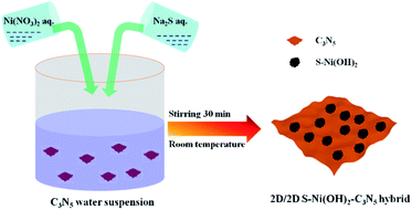
Herein, taking 2D C3N5 as a model semiconductor, 2D S-doped Ni(OH)2 (denoted as S–Ni(OH)2) was facilely planted on its surface by a one-step precipitation method between Ni(NO3)2 and Na2S in water (co-existence of S2− and OH−) under stirring within 30 minutes at room temperature, as revealed in Scheme 1. The hybrid photocatalyst (S–Ni(OH)2–C3N5) was evaluated by photocatalytic activity for H2 production and NO oxidation removal. Experimental results depicted that S–Ni(OH)2 can promote the photogenerated e−/h+ separation of C3N5 after light excitation and favor the generation of active oxygen species (ROS) participating in the subsequent photocatalytic procedure. In particular, the visible-light-induced photocatalytic H2 production rate over S–Ni(OH)2–C3N5 is even higher than that of Pt–C3N5, while the cost of S–Ni(OH)2 (taking the H2 production test as an example: in 45 mg 1.0 wt% S–Ni(OH)2–C3N5) is calculated to be just ∼0.0032 ¥ or ∼0.00049 $ based on the price of Ni(NO3)2 and Na2S. The present work provides new insights into the design of low-cost and noble-metal-free catalysts for energy and environmental applications.
Experimental section
Material preparation
All chemicals used were purchased from Aladdin and used without purification. C3N5 was prepared by heating 3-amino-1,2,4-triazole at 500 °C in air according to our previous work.36 Generally, S–Ni(OH)2–C3N5 was synthesized by mixing a certain amount of C3N5, Ni(NO3)2 and Na2S in water and stirring for 30 min. And then, the precipitate was washed with distilled water and absolute ethanol several times and dried in a vacuum at 80 °C for 12 h. The loading amount of S–Ni(OH)2 on C3N5 was calculated based on the initial input nickel mass fraction in the hybrid, and a series of S–Ni(OH)2–C3N5 hybrids with S–Ni(OH)2 loading amount varying between 0.5 and 3.0 wt% were prepared by changing the amount of Ni(NO3)2 and Na2S accordingly. Pristine S–Ni(OH)2 was also prepared by the same method in the absence of C3N5. By the way, Ni(OH)2–C3N5 was prepared by the same method using NaOH instead of Na2S.Catalyst characterization
XRD patterns were recorded on a powder X-ray diffractometer with Cu Kα radiation (D8 Advance Bruker Inc., Germany). TEM and HRTEM images were acquired on an FEI TALOS F200. SEM and EDS mapping images were acquired on a Gemini Sigma 300. The Brunauer–Emmett–Teller (BET) specific surface area was evaluated using nitrogen adsorption–desorption apparatus (ASAP 2040, Micrometrics Inc., USA) with all samples degassed at 120 °C for 12 h prior to measurements. Valence state of each element in the catalyst was analyzed by X-ray photoelectron spectroscopy (XPS) on a Thermo Fisher ESCALAB 250Xi X-ray photoelectron spectroscope. A Shimadzu UV-3100 recording spectrophotometer and fluorescence spectrometer (F-4600, Hitachi Inc., Japan) were used to record UV-vis diffuse reflectance (DRS) and PL spectra measurements respectively. Time-resolved fluorescence spectra (TRFS) were obtained on an Edinburgh FLS 1000. Electron paramagnetic resonance (EPR) spectra were recorded on a JES-FA200 EPR spectrometer. 5,5-Dimethyl-1-pyrroline-N-oxide (DMPO) was used as a radical spin-trapping reagent for ˙OH and ˙O2−. 2,2,6,6-Tetramethylpiperidine (TEMP) was used as the trapping agent for 1O2.3 The photocurrent and electrochemical impedance measurements were recorded on a CHI 660D electrochemical workstation (Chenhua Instrument, Shanghai, China) with a conventional three electrode configuration. Pt foil and Ag/AgCl (saturated KCl) were used as the counter electrode and reference electrode respectively. The working electrode was made by spreading a catalyst/Nafion slurry on FTO glass and 0.1 M Na2SO4 aqueous solution was used as the electrolyte.Photocatalytic activity tests and photoelectrochemical measurements
The photocatalytic H2 production rate and AQY measurements were carried out on a top-irradiated reaction vessel containing the catalyst and sacrificial reagent (TEOA) connected to a closed gas system with a 300 W Xe-lamp (PLS SXE300, Beijing Perfectlight Inc., China) equipped with a cutoff filter (λ > 420 nm) or band-pass filters (λ = 420, 500 nm, etc.); the photocatalytic H2 production system is shown in Fig. S1.† The H2 production rate was detected using a GC (SP7820, TCD detector, 5 Å molecular sieve columns, and Ar carrier), and AQY values were calculated according to our previous work:17
 | (1) |
For photocatalytic NO removal, a continuous flow reactor under ambient conditions was adopted according to our previous work.7 The volume of the rectangular reactor was 4.5 L (30 cm × 15 cm × 10 cm). 25 mg catalyst was dispersed into the mixture of ethanol and water and then transferred into a culture dish with a diameter of 12 cm, and then the dish was placed in the reactor after the solvent was dried at 45 °C. A 30 W visible LED (General Electric) was used as a light source. The gas (containing NO and air) flow rate through the reactor was controlled at 1000 mL min−1 using a mass flow controller with an initial NO concentration of ∼600 ppb. The NO and NO2 concentrations were recorded on a NOx analyzer model T200 (Teledyne API). The generation of NO3− was detected by ion chromatography on a Thermo DIONEX ICS-900.
Results and discussion
Crystal phase and micro morphology analyses
The pristine S–Ni(OH)2 prepared from the ultrafast reaction between Ni2+ and Na2S in water under ambient conditions within 30 min is firstly detected by XRD, as depicted in Fig. S2,† which demonstrates the formation of S–Ni(OH)2 with low diffraction peaks corresponding to the PDF card of 73-1520 for Ni(OH)2, indicating the low crystallinity of the present S–Ni(OH)2 material. Herein, the confirmation of S doping will be illustrated in the following section. It should be noted that pristine Ni(OH)2 without S doping is prepared by reaction between Ni2+ and NaOH for comparison, and the diffraction peaks of this Ni(OH)2 are also in agreement with the same PDF card (Fig. S2†), indicating that the comparison is reasonable. For the XRD patterns of C3N5 and S–Ni(OH)2–C3N5 hybrid (Fig. 1a), only two distinct peaks corresponding to (100) and (002) planes of C3N5,32,35,36,45 are observed even with a high loading amount of S–Ni(OH)2 up to 3.0 wt%, which should relate to the low crystallinity of present S–Ni(OH)2. In addition, no obvious shift happens in the main peaks of C3N5 after the loading of S–Ni(OH)2, revealing that the procedure for hybrid preparation does not destroy the basic structure of C3N5.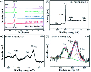 | ||
| Fig. 1 (a) XRD patterns of C3N5 and S–Ni(OH)2–C3N5 with different loading amounts of S–Ni(OH)2. (b) XPS survey, (c) Ni 2p and (d) S 2p spectra of 1.0 wt% S–Ni(OH)2–C3N5 respectively. | ||
The element component of 1.0 wt% S–Ni(OH)2–C3N5 is analyzed by elemental analysis and ICP-MS (Table S1†). From the elemental analysis result, the C/N ratio of the catalysts was determined to be 3![[thin space (1/6-em)]](https://www.rsc.org/images/entities/char_2009.gif) :
:![[thin space (1/6-em)]](https://www.rsc.org/images/entities/char_2009.gif) 4.7, which is much lower than that of C3N4 and very close to that of C3N5, and the result is in good agreement with previous literature.35 As revealed in Fig. 1b, S–Ni(OH)2–C3N5 is composed of C, N, Ni, O and S elements, demonstrating the existence of S-doping in Ni(OH)2 during the reaction between Ni2+ and Na2S preliminarily. In addition, the result depicts the successful combination of S–Ni(OH)2 and C3N5. The high resolution spectra of C 1s (Fig. S3a†) and N 1s (Fig. S3b†) in S–Ni(OH)2–C3N5 are similar to that of pristine C3N5 shown in our previous work,36 and no obvious peak shifts are found, revealing that the structure of C3N5 is well kept during the loading of S–Ni(OH)2. The existence of Ni ions is confirmed by the high resolution spectrum of Ni 2p, in which two distinct spin–orbit peaks at ∼855.8 (Ni 2p3/2) and ∼873.5 eV (Ni 2p1/2) along with two satellite peaks (identified as ‘‘Sat.’’) are clearly observed (Fig. 1c).40,42 The O 1s spectra mainly consist of a peak at 531.79 eV, (see Fig. S3c†) which can be assigned to the O2− species in Ni(OH)2.46 Most importantly, two peaks are observed in the high resolution spectrum of S 2p, in which the peak centered at ∼164 eV represents the metal–sulfur bond and S2−, while the other peak in the high binding energy region can be considered as residual SO42− adsorbed on the material (Fig. 1d).40,42,47 That is, the existence of the Ni–S bond can support the formation of S-doping in Ni(OH)2.
4.7, which is much lower than that of C3N4 and very close to that of C3N5, and the result is in good agreement with previous literature.35 As revealed in Fig. 1b, S–Ni(OH)2–C3N5 is composed of C, N, Ni, O and S elements, demonstrating the existence of S-doping in Ni(OH)2 during the reaction between Ni2+ and Na2S preliminarily. In addition, the result depicts the successful combination of S–Ni(OH)2 and C3N5. The high resolution spectra of C 1s (Fig. S3a†) and N 1s (Fig. S3b†) in S–Ni(OH)2–C3N5 are similar to that of pristine C3N5 shown in our previous work,36 and no obvious peak shifts are found, revealing that the structure of C3N5 is well kept during the loading of S–Ni(OH)2. The existence of Ni ions is confirmed by the high resolution spectrum of Ni 2p, in which two distinct spin–orbit peaks at ∼855.8 (Ni 2p3/2) and ∼873.5 eV (Ni 2p1/2) along with two satellite peaks (identified as ‘‘Sat.’’) are clearly observed (Fig. 1c).40,42 The O 1s spectra mainly consist of a peak at 531.79 eV, (see Fig. S3c†) which can be assigned to the O2− species in Ni(OH)2.46 Most importantly, two peaks are observed in the high resolution spectrum of S 2p, in which the peak centered at ∼164 eV represents the metal–sulfur bond and S2−, while the other peak in the high binding energy region can be considered as residual SO42− adsorbed on the material (Fig. 1d).40,42,47 That is, the existence of the Ni–S bond can support the formation of S-doping in Ni(OH)2.
To further confirm the successful fabrication of the S–Ni(OH)2–C3N5 hybrid, TEM and SEM images are acquired and shown in Fig. 2. It has been reported in our previous work that the micro morphology of pristine C3N5 is nanosheet.36 Fig. 2a and b display the TEM and HRTEM images of S–Ni(OH)2. As shown in Fig. 2a, S–Ni(OH)2 also exhibits a micro morphology of nanosheets and a clear lattice fringe of 0.23 nm corresponding to the (011) plane of S–Ni(OH)2 is observed (Fig. 2b). In particular, no lattice fringe representing nickel sulfide is found, demonstrating the existence state of S-doping in S–Ni(OH)2. Fig. 2c displays the TEM image of 1.0 wt% S–Ni(OH)2–C3N5, in which 2d nanosheets containing S–Ni(OH)2 and C3N5 are observed. In addition, S–Ni(OH)2 and C3N5 come into tight contact with each other and it is difficult to distinguish each material due to their similar micro morphology. The high resolution region (Fig. 2d) of S–Ni(OH)2–C3N5 can be clearly divided into an amorphous region corresponding to C3N5 and a crystalline region for S–Ni(OH)2 with a clear lattice fringe of 0.23 nm corresponding to the (011) plane of S–Ni(OH)2. By the way, the two different regions in Fig. 2d come into tight contact with each other, which will be favorable for the internal transfer of photogenerated carriers.
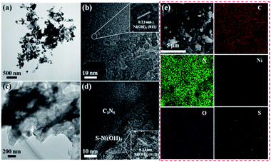 | ||
| Fig. 2 TEM and HRTEM of S–Ni(OH)2 (a and b) and 1.0 wt% S–Ni(OH)2–C3N5 (c and d). SEM and EDS mapping of 1.0 wt% S–Ni(OH)2–C3N5 (e). | ||
Fig. 2e depicts the SEM and element mapping images of 1.0 wt% S–Ni(OH)2–C3N5. As revealed, the hybrid is basically composed of nanosheets containing S–Ni(OH)2 and C3N5, which is in good agreement with the above results of TEM. The element mapping images convey that the hybrid contains C, N, Ni, O and S, and all of the elements disperse uniformly in the observed region. Moreover, the existence of S-doping in S–Ni(OH)2 is confirmed from the mapping of S in the material. Based on the above-mentioned XRD, XPS, TEM and SEM analyses, the product of reaction between Ni2+ and Na2S is named S–Ni(OH)2 considering that no any information corresponding to nickel sulfide is detected while the Ni–S bond exists in the hybrid, and the hybrid of 2D S–Ni(OH)2–C3N5 is successfully constructed.
DRS and e−/h+ separation analyses
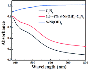
In the field of photocatalysis, the light responsive region plays a significant role in the performance of catalysts. The visible light absorption properties of S–Ni(OH)2, C3N5 and S–Ni(OH)2–C3N5 are compared in Fig. 3. In brief, C3N5 possesses a narrow band-gap of ∼2.25 eV according to our previous work,36 and can absorb the visible light region of 400–600 nm with high intensity, while pristine S–Ni(OH)2 exhibits a strong absorption across the spectral range of 200–2400 nm (Fig. S6†). For the hybrid material, 1.0 wt% S–Ni(OH)2–C3N5 exhibits a similar visible light absorption region to C3N5, but the absorption intensity is slightly increased by the hybridization of black S–Ni(OH)2. In a word, this wide and strong visible light absorption property of the hybrid is favorable for achieving high photocatalytic performance.Light absorption is the first step for a photocatalytic procedure, and the subsequent photogenerated e−/h+ separation is of great importance to the whole performance. Monitoring of the PL behavior of photocatalysts can find out some information on e−/h+ separation after light excitation.26,48,49 As revealed in the steady-state PL spectrum in Fig. 4a, C3N5 exhibits strong PL intensity, demonstrating its high photogenerated e−/h+ recombination rate after light excitation. However, the emission intensity of C3N5 can be efficiently quenched by S–Ni(OH)2. The lower PL intensity of 1.0 wt% S–Ni(OH)2–C3N5 than C3N5 demonstrates that the recombination of e−/h+ pairs on C3N5 after excitation is restrained, which should be caused by the electron transfer from C3N5 to S–Ni(OH)2 since Ni-based species such as nickel sulfide and Ni(OH)2 are often used as co-catalysts for photocatalytic H2 production.43,50–52 Mott–Schottky analysis was further conducted on S–Ni(OH)2 to verify whether the CB position of S–Ni(OH)2 is sufficient to capture the photogenerated electrons from C3N5 (Fig. S7†). The CB position of S–Ni(OH)2 was determined to be −0.58 V vs. NHE, which is less negative than that of C3N5 (−0.98 V vs. NHE).36 So, under irradiation, the photogenerated electrons of C3N5 could migrate to S–Ni(OH)2 and be captured. The time-resolved fluorescence spectra (TRFS) of C3N5 and 1.0 wt% S–Ni(OH)2–C3N5 are compared in Fig. 4b to further illustrate this viewpoint. As depicted, the PL intensity of C3N5 decays quickly after excitation, indicating its low fluorescence lifetime which is not favorable for photogenerated e−/h+ separation. However, the decay tendency of 1.0 wt% S–Ni(OH)2–C3N5 exhibits a clear slowdown under the same conditions, demonstrating that the fluorescence lifetime is prolonged, which should be related to the internal electron transfer from C3N5 to S–Ni(OH)2.18,53 For comparison, the fluorescence lifetime of C3N5 and 1.0 wt% S–Ni(OH)2–C3N5 is calculated to be ∼8.50 and 14.02 ns respectively via a biexponential fitting. The enhanced e−/h+ separation efficiency of 1.0 wt% S–Ni(OH)2–C3N5 compared to pristine C3N5 is further confirmed by photocurrent–time and EIS behaviors. As revealed in Fig. 4c, sharp photocurrent is generated under light irradiation and then decreases suddenly when light is turned off, demonstrating that the current is light-switched and produced by the photogenerated e−/h+ separation after the semiconductor is excited.20,54,55 In comparison, 1.0 wt% S–Ni(OH)2–C3N5 exhibits a much higher photocurrent value than pristine C3N5, indicating that the separation of photogenerated e−/h+ on C3N5 is facilitated by loading of the S–Ni(OH)2 co-catalyst. In addition, a smaller arc radius is recorded on the S–Ni(OH)2–C3N5 electrode, revealing the smaller resistance for charge transfer which is favorable for e−/h+ separation.53,56 All these results convey that the S–Ni(OH)2–C3N5 hybrid possesses quick internal charge transfer efficiency, which will facilitate the subsequent photocatalytic performance.
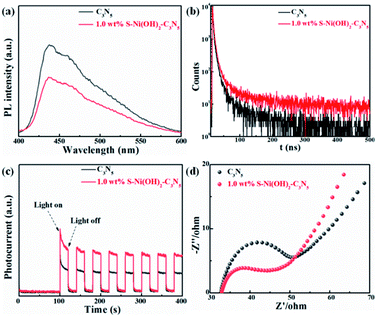 | ||
| Fig. 4 Comparison of steady-state PL (a), time-resolved PL (b), photocurrent-time (c) and EIS (d) curves of C3N5 and 1.0 wt% S–Ni(OH)2–C3N5. | ||
Photocatalytic H2 production performance
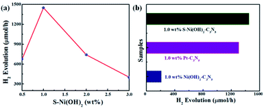
In consideration of the wide visible light absorption region and quick photogenerated e−/h+ separation efficiency of the S–Ni(OH)2–C3N5 hybrid, its photocatalytic performance for H2 production from water with TEOA as a sacrificial reagent under visible light irradiation (λ > 420 nm) is evaluated firstly. A blank experiment shows that almost no H2 production is observed on pristine C3N5 due to the lack of a co-catalyst. And pristine S–Ni(OH)2 also cannot produce H2 under these conditions. However, as displayed in Fig. 5a, the H2 production rate is dramatically enhanced even with a low loading amount of 0.5 wt% S–Ni(OH)2 on C3N5. Generally, a volcano-type relationship between the loading amount of a cocatalyst and the whole photocatalytic activity will be obtained,57 suggesting that the fraction of S–Ni(OH)2 in the hybrid must be screened to explore the highest H2 production rate. As shown in Fig. 5b, the maximum H2 production rate is 1450 μmol h−1 on the catalyst of 1.0 wt% S–Ni(OH)2–C3N5. Notably, excessive loading of S–Ni(OH)2 will influence the visible light absorption of C3N5, and then the whole photoactivity is decreased. In addition, the initial concentration of Na2S in the procedure of catalyst preparation will influence the concentration of OH− and S2−, which participate in the formation of S–Ni(OH)2. The influence of initial mol ratio between Ni2+ and Na2S (Ni/S) in the preparation procedure on the photoactivity is shown in Fig. S4,† and the selected condition for S–Ni(OH)2 preparation is Ni/S = 1/3.To explore the influence of S doping on the photocatalytic H2 production performance, the comparison of 1.0 wt% S–Ni(OH)2–C3N5 and 1.0 wt% Ni(OH)2–C3N5 is shown in Fig. 5b. Unexpectedly, 1.0 wt% Ni(OH)2–C3N5 exhibits much lower H2 production activity (209 μmol h−1), which is only one seventh of the value over the 1.0 wt% S–Ni(OH)2–C3N5 hybrid. That is to say, a novel method is explored to prepare a highly efficient Ni(OH)2-based co-catalyst by simply changing the initial reactant from NaOH to Na2S that reacts with Ni2+ under ambient conditions ultra-fast. The photocatalytic performance is also evaluated using Pt nanoparticles as a reference since Pt is generally considered as the most efficient co-catalyst for photocatalytic H2 production.15,23 As depicted in Fig. 5b, the H2 production rate on 1.0 wt% S–Ni(OH)2–C3N5 is slightly higher than that of 1.0 wt% Pt–C3N5, demonstrating that the present S–Ni(OH)2 is a highly efficient co-catalyst for H2 production and is promising in consideration of the facile preparation procedure and low cost of Ni-based materials compared with noble metals like Pt.
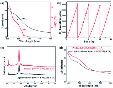
The AQY values of 1.0 wt% S–Ni(OH)2–C3N5 under a series of monochromatic light irradiation are shown in Fig. 6a, in which the AQY values decrease gradually with the increase of light wavelength and the highest AQY value (30.9%) is obtained at 420 nm. The change tendency of AQY is in agreement with the DRS spectrum of S–Ni(OH)2–C3N5, demonstrating that the photocatalytic performance of S–Ni(OH)2–C3N5 is determined by its light absorption behavior. Long-term stability of a photocatalyst is an important norm in the field of H2 production. Fig. 6b reveals the cycling performance of 1.0 wt% S–Ni(OH)2–C3N5 and no obvious attenuation of H2 production rate happens after 16 h and 4 runs of photocatalytic test, demonstrating the excellent photocatalytic stability of the present S–Ni(OH)2–C3N5 hybrid. To further evaluate the stability of S–Ni(OH)2–C3N5 in photocatalysis, the samples are collected after long-term light irradiation and monitored by XRD and DRS. As depicted in Fig. 6c and d, no obvious change happens in the XRD peaks of S–Ni(OH)2–C3N5 experiencing the photocatalytic test, indicating that the basic structure of the hybrid is maintained. Meanwhile, the collected sample exhibits a similar visible light absorption region compared with fresh S–Ni(OH)2–C3N5, demonstrating the stability of the hybrid again.
Photocatalytic NO oxidation performance
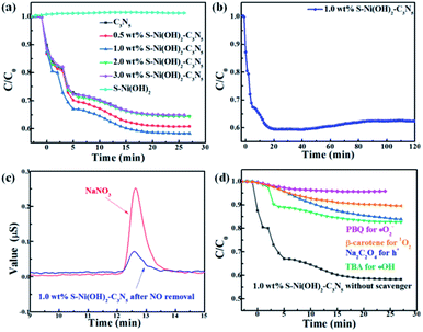
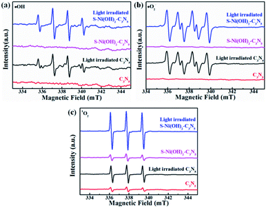
Except for H2 production, the photocatalytic performance of S–Ni(OH)2–C3N5 is also tested for NO oxidation to demonstrate the potential of the catalyst in purification of atmospheric pollution. A control experiment shows that pristine S–Ni(OH)2 has no activity for NO removal. As revealed in Fig. 7a, the oxidation of NO can reach equilibrium in 25 min in the present continuous flow reaction system. Briefly, NO removal efficiencies on C3N5 and S–Ni(OH)2–C3N5 with 0.5, 1.0, 2.0, and 3.0 wt% S–Ni(OH)2 fraction after 25 min of light irradiation are 35.0, 37.0, 42.0, 35.0 and 35.0% respectively and the most efficient catalyst is 1.0 wt% S–Ni(OH)2–C3N5 hybrid, indicating that the photocatalytic performance of C3N5 is enhanced by loading of S–Ni(OH)2. And the above-mentioned quick internal charge transfer from C3N5 to S–Ni(OH)2 under light excitation should play a significant role in this process. Fig. 7b evaluates the durability and stability of the 1.0 wt% S–Ni(OH)2–C3N5 hybrid for NO removal, and only a slight decrease in NO removal ratio is observed during 120 nm light irradiation, demonstrating the good stability of the hybrid. Generally, the main products of photocatalytic NO oxidation are NO2 and NO3− according to literature reports.58–60 The detection of NO2 is carried out on the present NOx analyzer, and the concentration of NO2 along with NO oxidation is shown in Fig. S5.† It is found that most NO is converted to NO3− based on the amount of NO removal and NO2 production. Therefore, the confirmation of produced NO3− in the reaction is shown in Fig. 7c with NaNO3 as a reference by ion chromatography, in which a clear signal corresponding to NO3− is observed for the sample prepared with 1.0 wt% S–Ni(OH)2–C3N5 experiencing photocatalytic NO oxidation reaction.It has been reported that activation of molecular O2 and generation of a series of ROS (i.e. ˙OH, ˙O2− and 1O2) play the main role in the procedure of photocatalytic NO oxidation.61–63 In addition, photogenerated h+ residual in the VB of the semiconductor is also of great importance.64,65 Thus, the photocatalytic NO removal performance of 1.0 wt% S–Ni(OH)2–C3N5 in the presence of a series of trapping agents for different active species is compared in Fig. 7d. As displayed, when Na2C2O4, tert-butanol (TBA), p-benzoquinone (PBQ) and β-carotene are used as scavengers for h+, ˙OH, ˙O2− and 1O2 respectively, the photocatalytic performance of 1.0 wt% S–Ni(OH)2–C3N5 is seriously restrained, demonstrating that NO is removed by these ROS and residual h+ in the VB of C3N5. The NO2 concentration during the photocatalytic NO removal on 1.0 wt% S–Ni(OH)2–C3N5 was also monitored with the NOx analyzer (see Fig. S8†). The corresponding residual ratio of NO2 is provided in Table S2.† From these results, it can be seen that the ˙OH and 1O2 play important roles in the conversion of NO2 to NO3−. Electron spin-resonance spectroscopy (ESR) tests are conducted to monitor the change of signals corresponding to ˙OH, ˙O2− and 1O2. As revealed in Fig. 8, almost no signals are detected in the dark on both 1.0 wt% S–Ni(OH)2–C3N5 and C3N5, but strong peaks corresponding to distinct DMPO-˙OH, DMPO-˙O2− and TEMPO (product of TEMP oxidized by 1O2) signals are detected,3,7,61 demonstrating that the generation of these ROS is light controllable. Moreover, the light induced ESR signal intensity on 1.0 wt% S–Ni(OH)2–C3N5 is higher than that of C3N5, revealing that more amount of ROS is generated on S–Ni(OH)2–C3N5 due to the quick internal charge transfer. So, the process of photocatalytic NO removal on 1.0 wt% S–Ni(OH)2–C3N5 should be as follows:
| S–Ni(OH)2–C3N5 + hv → e− + h+ | (2) |
| e− + h+ → ˙O2− | (3) |
| h+ + ˙O2− → 1O2 | (4) |
| ˙O2− + H2O → ˙OH | (5) |
| ˙O2−/1O2/h+/˙OH + NO → NO2 | (6) |
| 1O2/˙OH + NO2 → NO3− | (7) |
Based on all of the above results, the mechanism for photocatalytic H2 production or NO oxidation over the S–Ni(OH)2–C3N5 hybrid is proposed. Under visible light irradiation, C3N5 is excited and generates e−/h+ pairs. S–Ni(OH)2 can promote the internal charge separation and harvest the e− on the CB of C3N5, and then the trapped electrons participate in subsequent surface reactions. For photocatalytic H2 production (Fig. 9a), the collected electrons on S–Ni(OH)2 react with adsorbed H2O molecules and H2 is produced. The residual h+ on the VB of C3N5 is consumed by TEOA, and then the whole photocatalytic H2 production procedure is accomplished. However, the situation for photocatalytic NO oxidation is different (Fig. 9b). O2 is firstly activated and a series of ROS (˙O2−, 1O2 and ˙OH) can be generated. Generally, ˙O2− is produced by reaction between e− and adsorbed O2, while the reaction between ˙O2− and h+ can generate 1O2.3,61 ˙OH should originate from the oxidization of H2O by ˙O2− since the VB position of C3N5 cannot satisfy the requirement of ˙OH generation based on our previous work.33,66 In addition, the generation of these ROS is enhanced by S–Ni(OH)2, as discussed in the above section. And then, these ROS and the residual h+ on the VB of C3N5 participate in the NO oxidation procedure along with the formation of NO3− and NO2.
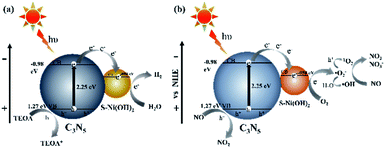 | ||
| Fig. 9 The supposed mechanism of photocatalytic H2 production (a) and NO removal (b) on 1.0 wt% S–Ni(OH)2–C3N5. | ||
Conclusions
In summary, near-zero-cost 2D S–Ni(OH)2 active sites are planted on wide visible light responsive C3N5 ultrafast within 30 min at room temperature by reaction between Ni(NO3)2 and Na2S in aqueous solution. The loading of S–Ni(OH)2 can greatly enhance the photogenerated e−/h+ separation efficiency of C3N5 after light excitation. Due to the quick internal charge transfer, the S–Ni(OH)2–C3N5 hybrid is highly efficient as a multifunctional catalyst in various photocatalytic applications: H2 production from water and NO removal. Most impressively, the H2 production activity on S–Ni(OH)2–C3N5 is even higher than that of Pt–C3N5 and an AQY value of 30.9% at 420 nm is achieved. This work brings new insights into the design of low-cost noble-metal-free co-catalysts on semiconductors for photocatalytic applications.Conflicts of interest
There are no conflicts to declare.Acknowledgements
This work was financially supported by the National Natural Science Foundation of China (21703075, 51872107, 52073110, and 22002047), Natural Science Foundation of Hubei Province (2020CFB694 and 2020CFB394) and Fundamental Research Funds for the Central Universities (2662020LXPY005 and 2662019QD018).Notes and references
- T. Banerjee, F. Podjaski, J. Kröger, B. P. Biswal and B. V. Lotsch, Nat. Rev. Mater., 2021, 6, 168–190 CrossRef CAS.
- Q. Wang and K. Domen, Chem. Rev., 2020, 120, 919–985 CrossRef CAS PubMed.
- X. Yang, S. Wang, T. Chen, N. Yang, K. Jiang, P. Wang, S. Li, X. Ding and H. Chen, Chin. J. Catal., 2021, 42, 1013–1023 CrossRef CAS.
- M. Rahman, M. Kibria and C. Mulins, Chem. Soc. Rev., 2020, 49, 1887–1931 RSC.
- Y. Wang, B. Gao, Q. Yue and Z. Wang, J. Mater. Chem. A, 2020, 8, 19133–19155 RSC.
- X. Zou, Z. Sun and Y. Hu, J. Mater. Chem. A, 2020, 8, 21474–21502 RSC.
- S. Wang, X. Ding, N. Yang, G. Zhan, X. Zhang, G. Dong, L. Zhang and H. Chen, Appl. Catal., B, 2020, 265, 118585 CrossRef CAS.
- Z. Wang, C. Li and K. Domen, Chem. Soc. Rev., 2019, 48, 2109–2125 RSC.
- B. Zhang and L. Sun, Chem. Soc. Rev., 2019, 48, 2216–2264 RSC.
- W. Yang, R. Prabhakar, J. Tan, S. Tilley and J. Moon, Chem. Soc. Rev., 2019, 48, 4979–5015 RSC.
- Y. Wang, A. Vogel, M. Sachs, R. Sprick, L. Wilbraham, S. Moniz, R. Godin, M. Zwijnenburg, J. Durrant, A. Cooper and J. Tang, Nat. Energy, 2019, 4, 746–760 CrossRef CAS.
- Q. Xu, L. Zhang, B. Cheng, J. Fan and J. Yu, Chem, 2020, 6, 1543–1559 CAS.
- J. Fu, J. Yu, C. Jiang and B. Cheng, Adv. Energy Mater., 2018, 8, 1701503 CrossRef.
- X. Yang, Z. Hu, Q. Yin, C. Shu, X. Jiang, J. Zhang, X. Wang, J. Jiang, F. Huang and Y. Cao, Adv. Funct. Mater., 2019, 29, 1808156 CrossRef.
- D. Zhao, Y. Wang, C. Dong, Y. Huang, J. Chen, F. Xue, S. Shen and L. Guo, Nat. Energy, 2021, 6, 388–397 CrossRef CAS.
- K. Gottschling, G. Savasci, H. Vignolo-Gonzalez, S. Schmidt, P. Mauker, T. Banerjee, P. Rovo, C. Ochsenfeld and B. V. Lotsch, J. Am. Chem. Soc., 2020, 142, 12146–12156 CrossRef CAS PubMed.
- X. Zhang, J. Xiao, M. Hou, Y. Xiang and H. Chen, Appl. Catal., B, 2018, 224, 871–876 CrossRef CAS.
- F. Xu, K. Meng, B. Cheng, S. Wang, J. Xu and J. Yu, Nat. commun., 2020, 11, 4613 CrossRef CAS PubMed.
- J. Wang, L. Xu, T. Wang, R. Li, Y. Zhang, J. Zhang and T. Peng, Adv. Energy Mater., 2021, 11, 2003575 CrossRef CAS.
- J. Wang, M. Kuo, P. Zeng, L. Xu, S. Chen and T. Peng, Appl. Catal., B, 2020, 279, 119377 CrossRef CAS.
- T. Takata, J. Jiang, Y. Sakata, M. Nakabayashi, N. Shibata, V. Nandal, K. Seki, T. Hisatomi and K. Domen, Nature, 2020, 581, 411–414 CrossRef CAS PubMed.
- X. Wang, K. Maeda, A. Thomas, K. Takanabe, G. Xin, J. M. Carlsson, K. Domen and M. Antonietti, Nat. Mater., 2009, 8, 76–80 CrossRef CAS PubMed.
- L. Lin, Z. Lin, J. Zhang, X. Cai, W. Lin, Z. Yu and X. Wang, Nat. Catal., 2020, 3, 649–655 CrossRef CAS.
- G. Zhang, G. Li, T. Heil, S. Zafeiratos, F. Lai, A. Savateev, M. Antonietti and X. Wang, Angew. Chem., Int. Ed., 2019, 58, 3433–3437 CrossRef CAS PubMed.
- Y. Xiao, G. Tian, W. Li, Y. Xie, B. Jiang, C. Tian, D. Zhao and H. Fu, J. Am. Chem. Soc., 2019, 141, 2508–2515 CrossRef CAS PubMed.
- T. H. T. Vinh, C. M. Thi and P. V. Viet, Mater. Lett., 2020, 281, 128637 CrossRef.
- V. V. Pham, D. Q. Mai, D. P. Bui, T. V. Man, B. Zhu, L. Zhang, J. Sangkaworn, J. Tantirungrotechai, V. Reutrakul and T. M. Cao, Environ. Pollut., 2021, 286, 117510 CrossRef PubMed.
- P. V. Viet, T. D. Nguyen, D. P. Bui and C. M. Thi, J. Materiomics, 2021 DOI:10.1016/j.jmat.2021.06.006.
- L. Zhang, R. Long, Y. Zhang, D. Duan, Y. Xiong, Y. Zhang and Y. Bi, Angew. Chem., Int. Ed., 2020, 59, 6224–6229 CrossRef CAS PubMed.
- X. Jiang, L. Zhang, H. Liu, D. Wu, F. Wu, L. Tian, L. Liu, J. Zou, S. Luo and B. Chen, Angew. Chem., Int. Ed., 2020, 59, 23112–23116 CrossRef CAS PubMed.
- P. Kumar, E. Vahidzadeh, U. K. Thakur, P. Kar, K. M. Alam, A. Goswami, N. Mahdi, K. Cui, G. M. Bernard, V. K. Michaelis and K. Shankar, J. Am. Chem. Soc., 2019, 141, 5415–5436 CrossRef CAS PubMed.
- J. Zhang, B. Jing, Z. Tang, Z. Ao, D. Xia, M. Zhu and S. Wang, Appl. Catal., B, 2021, 289, 120023 CrossRef CAS.
- M. Li, Q. Lu, M. Liu, P. Yin, C. Wu, H. Li, Y. Zhang and S. Yao, ACS Appl. Mater. Interfaces, 2020, 12, 38266–38274 CrossRef CAS PubMed.
- I. Y. Kim, S. Kim, X. Jin, S. Premkumar, G. Chandra, N. S. Lee, G. P. Mane, S. J. Hwang, S. Umapathy and A. Vinu, Angew. Chem., Int. Ed., 2018, 57, 17135–17140 CrossRef CAS PubMed.
- G. P. Mane, S. N. Talapaneni, K. S. Lakhi, H. Ilbeygi, U. Ravon, K. Al-Bahily, T. Mori, D. H. Park and A. Vinu, Angew. Chem., Int. Ed., 2017, 56, 8481–8485 CrossRef CAS PubMed.
- C. Peng, L. Han, J. Huang, S. Wang, X. Zhang and H. Chen, Chin. J. Catal., 2021, 42 DOI:10.1016/S1872-2067(21)63813-5.
- T. Simon, N. Bouchonville, M. J. Berr, A. Vaneski, A. Adrović, D. Volbers, R. Wyrwich, M. Döblinger, A. S. Susha, A. L. Rogach, F. Jäckel, J. K. Stolarczyk and J. Feldmann, Nat. Mater., 2014, 13, 1013–1018 CrossRef CAS PubMed.
- X. Zhao, J. Feng, J. Liu, W. Shi, G. Yang, G. C. Wang and P. Cheng, Angew. Chem., Int. Ed., 2018, 57, 9790–9794 CrossRef CAS PubMed.
- Z. Sun, H. Zheng, J. Li and P. Du, Energy Environ. Sci., 2015, 8, 2668–2676 RSC.
- L. Yu, L. Wu, B. McElhenny, S. Song, D. Luo, F. Zhang, Y. Yu, S. Chen and Z. Ren, Energy Environ. Sci., 2020, 13, 3439–3446 RSC.
- X. Jin, R. Wang, L. Zhang, R. Si, M. Shen, M. Wang, J. Tian and J. Shi, Angew. Chem., Int. Ed., 2020, 59, 6827–6831 CrossRef CAS PubMed.
- H. Zou, B. He, P. Kuang, J. Yu and K. Fan, Adv. Funct. Mater., 2018, 28, 1706917 CrossRef.
- A. Yan, X. Shi, F. Huang, M. Fujitsuka and T. Majima, Appl. Catal., B, 2019, 250, 163–170 CrossRef CAS.
- L. Yu, L. Wu, B. McElhenny, S. Song, D. Luo, F. Zhang, Y. Yu, S. Chen and Z. Ren, Energy Environ. Sci., 2020, 13, 3439–3446 RSC.
- J. Zhang, H. Tao, S. Wu, J. Yang and M. Zhu, Appl. Catal., B, 2021, 296, 120372 CrossRef CAS.
- G. S. Gund, D. P. Dubal, S. B. Jambure, S. S. Shinde and C. D. Lokhande, J. Mater. Chem. A, 2013, 1, 4793 RSC.
- G. Zhang, Y. S. Feng, W. T. Lu, D. He, C. Y. Wang, Y. K. Li, X. Y. Wang and F. F. Cao, ACS Catal., 2018, 8, 5431–5441 CrossRef CAS.
- J. Fu, Q. Xu, J. Low, C. Jiang and J. Yu, Appl. Catal., B, 2019, 243, 556–565 CrossRef CAS.
- Y. Ren, Y. Li, X. Wu, J. Wang and G. Zhang, Chin. J. Catal., 2021, 42, 69–77 CrossRef CAS.
- Y. Luo, J. Qin, G. Yang, S. Luo, Z. Zhao, M. Chen and J. Ma, Chem. Engineer. J., 2021, 410, 128394 CrossRef CAS.
- G. X. Zhao, W. Zhou, Y. B. Sun, X. K. Wang, H. M. Liu, X. G. Meng, K. Chang and J. H. Ye, Appl. Catal., B, 2018, 226, 252–257 CrossRef CAS.
- Q. Lin, Y. H. Li, M. Y. Qi, J. Y. Li, Z. R. Tang, M. Anpo, Y. M. A. Yamada and Y. J. Xu, Appl. Catal., B, 2020, 271, 118946 CrossRef CAS.
- P. Xia, M. Antonietti, B. Zhu, T. Heil, J. Yu and S. Cao, Adv. Funct. Mater., 2019, 29, 1900093 CrossRef.
- B. Chai, T. Peng, J. Mao, K. Li and L. Zan, Phys. Chem. Chem. Phys., 2012, 14, 16745–16752 RSC.
- K. Li, B. Chai, T. Peng, J. Mao and L. Zan, ACS Catal., 2013, 3, 170–177 CrossRef CAS.
- G. Zuo, Y. Wang, W. Teo, A. Xie, Y. Guo, Y. Dai, W. Zhou, D. Jana, Q. Xian, W. Dong and Y. Zhao, Angew. Chem., Int. Ed., 2020, 59, 11287–11292 CrossRef CAS PubMed.
- J. Ran, J. Zhang, J. Yu, M. Jaroniec and S. Z. Qiao, Chem. Soc. Rev., 2014, 43, 7787–7812 RSC.
- P. Chen, H. Liu, Y. Sun, J. Li, W. Cui, L. a. Wang, W. Zhang, X. Yuan, Z. Wang, Y. Zhang and F. Dong, Appl. Catal., B, 2020, 264, 118545 CrossRef CAS.
- Y. Geng, D. Chen, N. Li, Q. Xu, H. Li, J. He and J. Lu, Appl. Catal., B, 2021, 280, 119409 CrossRef CAS.
- H. Shang, S. Huang, H. Li, M. Li, S. Zhao, J. Wang, Z. Ai and L. Zhang, Chem. Engineer. J., 2020, 386, 124047 CrossRef CAS.
- M. Kou, Y. Deng, R. Zhang, L. Wang, P. K. Wong, F. Su and L. Ye, Chin. J. Catal., 2020, 41, 1480–1487 CrossRef CAS.
- X. Shi, P. Wang, W. Li, Y. Bai, H. Xie, Y. Zhou and L. Ye, Appl. Catal., B, 2019, 243, 322–329 CrossRef CAS.
- W. Huo, T. Cao, W. Xu, Z. Guo, X. Liu, H. C. Yao, Y. Zhang and F. Dong, Chin. J. Catal., 2020, 41, 268–275 CrossRef CAS.
- J. Hu, D. Chen, Z. Mo, N. Li, Q. Xu, H. Li, J. He, H. Xu and J. Lu, Angew. Chem., Int. Ed., 2019, 58, 2073–2077 CrossRef CAS PubMed.
- D. Liu, D. Chen, N. Li, Q. Xu, H. Li, J. He and J. Lu, Angew. Chem., Int. Ed., 2020, 59, 4519–4524 CrossRef CAS PubMed.
- S. Wang, X. Ding, X. Zhang, H. Pang, X. Hai, G. Zhan, W. Zhou, H. Song, L. Zhang, H. Chen and J. Ye, Adv. Funct. Mater., 2017, 27, 1703923 CrossRef.
Footnotes |
| † Electronic supplementary information (ESI) available. See DOI: 10.1039/d1ra07275g |
| ‡ Lixiao Han and Cong Peng contribute equally to the work. |
| This journal is © The Royal Society of Chemistry 2021 |

