DOI:
10.1039/D1RA06969A
(Paper)
RSC Adv., 2021,
11, 37233-37245
Efficient recovery of Cr(VI) from electroplating wastewater by iron-modified sludge-based hollow-structured porous carbon: coexistence effects and competition for adsorption†
Received
17th September 2021
, Accepted 2nd November 2021
First published on 18th November 2021
Abstract
In the present work, porous carbon was made from sewage sludge and hybrid liriodendron leaves, and modified with iron ions (Fe@LS-BC) carried out on Cr(VI) in aqueous solution from a single-component system and in competitive biosorption with methyl orange (MO) from a binary-component system. The iron ion-modified porous carbon (Fe@LS-BC) showed higher efficiency in the removal of Cr(VI) compared to porous carbon prepared by the co-pyrolysis of sludge and hybrid liriodendron leaves. The incorporation of the Fe element improved the ability of the material to redox Cr(VI), while imparting magnetic characteristics to the porous carbon and improving the reusability of the porous carbon. On the other hand, Fe@LS-BC exhibited a better pore volume, facilitating the contact of the material with Cr(VI) ions. The highest adsorption capacity was 0.33 mmol g−1, and the adsorption experimental results for the single-component and binary-component systems of Cr(VI) matched well with the Langmuir–Freundlich models. When the concentration of MO was 0.2 and 0.8 mmol L−1, respectively, the highest adsorption capacity of Cr(VI) was 0.35 and 0.46 mmol g−1 in the binary system. The positively charged N–CH3+ on the MO molecule promoted the electrostatic adsorption between HCrO4−, CrO42−, and Fe@LS-BC, and increased the adsorption potential of Cr(VI).
1. Introduction
Electroplating, printing, pharmaceuticals, metallurgy, papermaking, leather, dyeing, and other industries utilize chromium (Cr) as a heavy metal representative.1 Electroplating is a significant surface treatment activity. The addition of a chromium plating layer improves corrosion resistance and surface hardness, but a large amount of high-concentration Cr(VI) effluent will be generated during the electroplating process. In the environment, the most prevalent forms of chromium are Cr(VI) and Cr(III). It is worth mentioning that Cr(III) is beneficial to the body in trace amounts.2 However, Cr(VI) has the characteristics of being easily soluble in water, and in higher amounts is extremely poisonous, highly oxidized, carcinogenic, and mutagenic. As a consequence, removing Cr(VI) from aqueous solutions before they wind up in wastewater, threatening human health and wreaking havoc on the environment, is essential. Synthetic dyes (e.g., Rhodamine B (RhB), methylene blue (MB), and methyl orange (MO)) and their by-products, which are highly carcinogenic, highly toxic, and difficult to degrade, are not easily degraded and removed from water.3–5 Consequently, how to efficiently remove these dyes that are widely used in industrial production has attracted a lot of attention from researchers. Membrane separation,6 ion-exchange,7 and biological methods8 are among the technologies that have been advanced and utilized to diminish the concentrations of Cr(VI) in aquatic environments. However, because of the high operating and maintenance costs, these technologies are severely restricted in terms of their widespread adoption. Techniques involving of adsorption have been broadly implemented for the elimination of contaminants from water owing to their cheap cost, facile procedure, easy availability of raw materials, high adsorption efficiency, and broad spectrum of adsorbed contaminants.9
Researchers are dedicated to discovering the most cost-effective materials to utilize as raw materials for adsorbents. Using inexpensive or easily accessible materials to produce adsorbents may significantly decrease the operating costs of the adsorption technology; for example, utilizing the hydrothermal synthesis of biomass to prepare carbon nanomaterials and the combustion of cellulose and graphene oxide to synthesize composites, both of which tend to exhibit a better pore-capacity morphology and multilevel pore-size distribution.10,11 Sludge is a complicated combination of heterogeneous phases, and dumping it into the environment without treatment can result in secondary pollution.12 Landfill and incineration are efficient methods for treating sludge, but have the disadvantage of contaminating the soil, leaking toxic substances, emitting toxic gases, and not effectively treating heavy metals in the residual ash.13 The catalytic pyrolysis of sludge involves no secondary contamination, and produces by-products with usable value, but incurs relatively high energy consumption.14 Sewage sludge contains a significant quantity of organic materials, and hence using sludge as a raw material for porous carbon has been well-established as novel kind of sludge disposal technique that can produce excellent economic, social, and environmental benefits.13 However, the carbon content of the sludge is typically low, and pyrolysis-produced porous carbon tends to have a poorly formed pore structure and possesses a low specific surface area. According to these features, the general use of porous carbon produced from sludge as a raw material is limited. Carbonaceous materials from biomass waste have been widely used to make sorbents, such as corncob15 and leaves.16 On the one hand, nanocellulose prepared using cellulose can be used not only as an adsorbent for organic solvents but also as a motor for supercapacitors;17,18 while on the other hand, porous carbon produced from lignocellulosic biomass has low density and is difficult to store or transport. Consequently, the co-pyrolysis of lignocellulosic biomass as well as sewage sludge may effectively alleviate the drawbacks of both kinds of porous carbon and enhance their capacity to remove contaminants while enabling the effective disposal of sewage sludge.19
In addition to being used as an adsorbent to remove pollutants from water, porous carbon can also be used to remove benzene to purify volatile organic gases,20 as an oxygen reduction electrocatalysts21 and in electromagnetic wave absorption.22 Porous carbon, on the other hand, is often manufactured in powder form for enhancing the specific surface area, making its removal arduous from aqueous solutions and hence limiting its practical use.23 For example, through the thermal decomposition of FeCl3, γ-Fe2O3 particles are doped on the surface of the porous carbon to impart the magnetism property, and then the porous carbon is recovered using magnetic separation techniques.24 It has been exhibited that through chemisorption, Fe(III) has demonstrated a potent affinity for the Cr anion.25 On the other hand, a notable quantity of research works has elucidated that the methods of adsorption can effectively remove inorganic and organic contaminants from aqueous solutions.26 Such studies have so far concentrated on the single-component system adsorption process, whereas the binary or multivariate-component system is closer to the real contaminated water body. In a binary-component system, Cr(VI) and methylene blue act together to improve the adsorption capacity.27 The inclusion of Cu2+, U6+, or Eu3+ in the binary-component system may increase Cr(VI) adsorption.28,29 As a result, porous carbon made from sewage sludge and lignocellulosic biomass is in high demand for pollutant adsorption in multivariate-component systems.
Consequently, FeCl3 was utilized to alter porous carbon made from sewage sludge and liriodendron leaves. In the systems of binary and single components, the performance and mechanism of adsorption for methyl orange (MO) and Cr(VI) on Fe@LS-BC were studied. To achieve efficacious Cr(VI) adsorption in aqueous solutions, operational factors, for instance the pH, starting concentrations, temperature, dosage of adsorbent, and contact time, were studied. By taking advantage of kinetic models, namely the intraparticle diffusion model, pseudo-second-order kinetic model, and pseudo-first-order kinetic model, the adsorption mechanisms were explored. To match the equilibrium isotherm data of the adsorption, various isotherm models, including Langmuir–Freundlich, Langmuir, and Freundlich, were implemented. Simultaneously, energy dispersive spectrometry (EDS), scanning electron microscopy (SEM), Fourier transform infrared spectrometry (FTIR), X-ray diffraction (XRD), thermogravimetric analysis (TGA), and X-ray photoelectron spectroscopy (XPS) were employed to explore the physicochemical properties of the test materials LS-BC and Fe@LS-BC.
2. Materials and methods
2.1 Feedstocks
Liriodendron leaves and sewage sludge were used for porous carbon production. Nanjing Forestry University in China gathered the liriodendron leaves. Sewage sludge was collected from a dewatering chamber at the Qiao Bei wastewater treatment facility in Nanjing, China. The liriodendron leaf and sewage sludge samples have been used for biochar production in previous studies.30 All the samples were washed in deionized water before being dried for 12 h at 110 °C. They were subsequently crushed and sieved into a powder with a particle size of less than 300 μm, with the powder then kept in plastic bags. NaOH (0.1 mol L−1) or HCl (0.1 mol L−1) were used to alter the pH of the solution. Sodium hydroxide, methyl orange, 95% sulfuric acid, 99.8% potassium dichromate, acetone, and 36% hydrochloric acid were supplied by Nanjing (China). All of the compounds were analytical grade and the subsequent tests did not need any additional purification steps. The chemical structure of methyl orange is given in the ESI section (Table S1†).
2.2 Preparation of FeCl3-modified porous carbon
Iron-loaded porous carbon was prepared according to our previous study, and the preparation process is shown in Fig. 1(a).30 The dried sludge and liriodendron leaves (2![[thin space (1/6-em)]](https://www.rsc.org/images/entities/char_2009.gif) :3, m/m) were combined in a beaker with a volume of 250 mL and subsequently impregnated in a 3 mol L−1 solution of ZnCl2 (ZnCl2:raw material = 3:1, m/m) for 24 h at 25 °C. After mixing, the slurry was centrifuged for 6 min at 3000 rpm before being vacuum dried for 8 h at 110 °C. For maintaining the oxygen-depleted circumstances, the specimens were wrapped by three layers of tin foils, and next they were pyrolyzed in a muffle furnace for 45 min at 550 °C (heating rate of 5 °C min−1). With the help of deionized water and a solution of 1 mol L−1 HCl, the considered porous carbon was washed many times until the pH was neutral. It was then dried for 8 h at 110 °C and crushed to a fineness of less than 50 mesh. The material made by the above steps was labeled as LS-BC.
:3, m/m) were combined in a beaker with a volume of 250 mL and subsequently impregnated in a 3 mol L−1 solution of ZnCl2 (ZnCl2:raw material = 3:1, m/m) for 24 h at 25 °C. After mixing, the slurry was centrifuged for 6 min at 3000 rpm before being vacuum dried for 8 h at 110 °C. For maintaining the oxygen-depleted circumstances, the specimens were wrapped by three layers of tin foils, and next they were pyrolyzed in a muffle furnace for 45 min at 550 °C (heating rate of 5 °C min−1). With the help of deionized water and a solution of 1 mol L−1 HCl, the considered porous carbon was washed many times until the pH was neutral. It was then dried for 8 h at 110 °C and crushed to a fineness of less than 50 mesh. The material made by the above steps was labeled as LS-BC.
 |
| | Fig. 1 Preparation process of porous carbon (a), and schematic diagram of the Cr(VI) concentration measurement process (b). | |
In the solution of 0.05 mol L−1 FeCl3 solution, the soaking of LS-BC was performed (LS-BC:FeCl3 = 1:4, m/m) for 24 h at 110 °C. The filtrate was rinsed with deionized water and drained until the filtrate clarified. Next, the materials were dried for 8 h at 110 °C and crushed to less than 50 mesh before calcination in a muffle furnace for 60 min at 600 °C, yielding Fe@LS-BC.
2.3 Characterization
To describe the morphology of the surface and microstructure of the samples, field emission scanning electron microscopy (FE-SEM) was employed, and energy dispersive spectrometry (EDS) was employed to explore the surface composition and element map (JSM-7600F, Japan). The surface area employing Brunauer–Emmett–Teller (BET), pore volume, and diameters of the pores for the products were measured with the aid of N2 adsorption and desorption isotherms (ASAP3020, Micromeritics, USA). Thermogravimetric analysis (TGA) was executed on a TA Q5000IR instrument at a heating rate of 10 °C min−1. Fourier transform infrared spectroscopy (FTIR) was employed to analyze the functional groups of the surface for the sample's pre-adsorption and post-adsorption (VERTEX 80V, Brooke, German), and the spectra were obtained in the range of 4000 to 400 cm−1. X-ray diffraction (XRD) (Ultima IV, Rigaku, Japan) measurements were carried out using a diffractometer with Cu-Kα radiation (λ = 1.5418 Å, 40 kV, 35 mA) within the scanning angle range of 10°–70°. X-ray photoelectron spectroscopy (XPS) (AXIS Ultra DLD, Dao Jing, UK) was used to ascertain the chemical oxidation state, elemental composition, and content of the LS-BC and Fe@LS-BC samples.
2.4 Batch tests
2.4.1 Cr(VI) adsorption experiments. In 250 mL conical flasks, batch biosorption studies were carried out with 50 mL of the solution of Cr(VI) and a specific amount of porous carbon. A thermostatic shaker incubator (200 rpm) was used to shake the mixture. For the kinetics assessment, the addition of 20 mg of adsorbent to a 50 mL aqueous solution was performed at a temperature of 25 °C and pH 2. The time range of the adsorption reaction was selected from 10 to 540 min and the concentrations of Cr(VI) were selected as 30, 40, and 50 mg L−1, respectively. To survey the influence of the pH on the adsorption, the primary pH of the solution was kept between 2–7, while the adsorbent was added at concentrations of 10, 20 and 30 mg, respectively. To scrutinize the influence of the Cr(VI) concentration on the elimination rate of Cr(VI), the Cr(VI) solution concentrations range was 2–100 mg L−1, while three temperature gradients were set at 25 °C, 35 °C, and 45 °C accordingly. During the adsorption procedure, 10, 30, and 50 mg L−1 of interfering ions were combined with the Cr(VI) solution to fully grasp the competitive adsorption interaction between coexisting ions (CO32−, NO3−, SO42−, PO43−, Zn2+, Mg2+, Na+, and K+).
2.4.2 Cr(VI) and MO binary-component system. First, 4 g L−1 Fe@LS-BC was added to the solution of Cr(VI) for the binary-system adsorption investigations, wherein the starting value of pH for each solution was changed to 2.0, and the reactants were agitated for 360 min at 25 °C. The primary concentration of Cr(VI) in the binary-component system was regulated between 0.1 °C 0.8 mmol L−1, while the MO concentration was controlled within 0.2 and 0.8 mmol L−1 accordingly. The filtration of the adsorbed samples was carried out with the aid of 0.45 μm Millipore HA membranes after shaking for a certain amount of time, and the concentration of Cr(VI) was ascertained through the 1,5-diphenylcarbohydrazide spectrophotometric approach employing a UV-Vis spectrophotometer (L5S, Shanghai, China), with the measurement wavelengths of Cr(VI) and MO at 540 and 460 nm, respectively. The Cr(VI) concentration measurement process is illustrated in Fig. 1(b).The removal efficiency (E, %) for Cr(VI) was calculated using eqn (1):
| |
 | (1) |
where
Ci represents the primary concentration of Cr(
VI) or MO (mg L
−1) and (mmol L
−1), and
Ce implies the concentration of Cr(
VI) or MO following the adsorption (mg L
−1) and (mmol L
−1).
The equilibrium adsorption capacity of Fe@LS-BC on Cr(VI) and MO is given by the following formula eqn (2):
| |
 | (2) |
where
qe ((mg g
−1), (mmol g
−1)) represents the amount adsorbed at equilibrium, and
V and
W are the volume of the solution of Cr(
VI) and MO (L) and the weight of Fe@LS-BC (g), respectively.
2.5 Models for equilibrium
2.5.1 Langmuir isotherm. The following form eqn (3) represents the Langmuir isotherm:31| |
 | (3) |
The maximum adsorbed quantity of contaminant per unit weight of sorbent is Q0 ((mg g−1), (mmol g−1)) and the Langmuir constant is KL ((L mg−1), (L mmol−1)).
The affinity of the binding sites is linked to KL. A greater KL value in binary systems implies the solute is readily adsorbed.
2.5.2. Freundlich isotherm. In contrast to the Langmuir isotherm, the Freundlich isotherm as an empirical equation is usually applied for multilayer adsorption. The Freundlich isotherm assumes the form of eqn (4):32where KF ((L mmol−1), (L mg−1)) and n are the Freundlich constant.
2.5.3 Langmuir–Freundlich isotherm. According to this model, the adsorbent surface is regarded as being homogeneous and the sorption is a cooperative procedure owing to adsorbate–adsorbate interactions. The Langmuir–Freundlich isotherm is illustrated in eqn (5):| |
 | (5) |
3. Results and discussion
3.1 Characterization of LS-BC and Fe@LS-BC
The SEM images present the surface and microstructure of LS-BC and Fe@LS-BC (Fig. 2(a)–(d)). LS-BC displayed a tubular configuration and a rich pore structure after 550 °C pyrolysis. Fe@LS-BC had a large number of tiny impurity particles on its surface, and irregularly shaped and ordered pores that were extremely deep. After high temperature pyrolysis, the excessive pore depth was generated by the activated sample under the action of HCl. Because of the alteration of ferric chloride, the surface of Fe@LS-BC was covered with tiny particles of contaminants. The pore structure of porous carbon Fe@LS-BC provided sufficient and excellent adsorption sites for adsorbents, which may enhance the pollutant removal efficiency. For the porous carbon, the EDS image is presented in Fig S1(a–c).† The EDS elemental mapping of LS-BC and Fe@LS-BC clearly revealed the distribution of C, O, Zn, Si, S, N, and Fe elements. The EDS analysis confirmed that oxygen and carbon were the main elemental components of the porous carbon, while also some inorganic elements were present, such as silicon, zinc, and iron. The EDS findings of Fe@LS-BC revealed a spike of iron element due to the activation by FeCl3 on the top surface of the sample, and it can be seen that after ferric chloride modification, the distribution of iron on the Fe@LS-BC surface became more widespread, with no apparent agglomeration phenomenon.
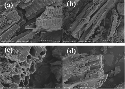 |
| | Fig. 2 SEM Images of the porous carbon (a), (b) LS-BC and (c), (d) Fe@LS-BC. | |
The thermogravimetric analysis (TGA) and derivative thermogravimetric (DTG) curves of porous carbon before and after ferric chloride alteration are shown in Fig. S2.† After modification with ferric chloride, these two kinds of porous carbon had comparable weight loss characteristics. The physisorbed water was responsible for the initial weight loss at temperatures below 120 °C, which was 3.146% for LS-BC and 3.363% for Fe@LS-BC, respectively. In the range of 120 °C to 400 °C, the mass of Fe@LS-BC stayed basically constant. From 400 °C to 560 °C, there was a substantial increase in mass loss. This degree of primary pyrolysis occurred, releasing the majority of the gases and creating the char's fundamental structure at an early stage.33 The thermal stability of the ferric chloride-modified porous carbon showed that it may be used at temperatures below 400 °C.
The chemisorption of contaminants is strongly linked to the surface functional groups of porous carbon, which affect its adsorption ability. Fig. 3 shows the FTIR spectra of Cr(VI) pre-adsorption and post-adsorption on Fe@LS-BC. In general, the spectra were comparable. The characteristic peak at 3436 cm−1 was allocated to –OH (hydroxyl group), whereas the peak at 1634 cm−1 was allocated to the stretching vibrations of C![[double bond, length as m-dash]](https://www.rsc.org/images/entities/char_e001.gif) C in aromatic rings or –N stretching, which decrease and shift following Cr(VI) absorption.34,35 The bending vibration of –NH2 in the amino group caused a peak at 1400 cm−1 in the Fe@LS-BC spectra before adsorption, which was shifted to 1392 cm−1.36 At 1097, 593, and 419 cm−1, the bands clearly related to Fe–O and C–O stretching vibrations and O–Si–O bending vibration were detected, respectively.37–39 Furthermore, these functional groups may overlap the signals closely related to the stretching vibration of CO and bending vibrations of N–H in porous carbon.40,41 The FTIR peak shifted from its initial location and intensity when Cr(VI) was adsorbed on the Fe@LS-BC, indicating that the adsorbent successfully adsorbed Cr(VI).42
C in aromatic rings or –N stretching, which decrease and shift following Cr(VI) absorption.34,35 The bending vibration of –NH2 in the amino group caused a peak at 1400 cm−1 in the Fe@LS-BC spectra before adsorption, which was shifted to 1392 cm−1.36 At 1097, 593, and 419 cm−1, the bands clearly related to Fe–O and C–O stretching vibrations and O–Si–O bending vibration were detected, respectively.37–39 Furthermore, these functional groups may overlap the signals closely related to the stretching vibration of CO and bending vibrations of N–H in porous carbon.40,41 The FTIR peak shifted from its initial location and intensity when Cr(VI) was adsorbed on the Fe@LS-BC, indicating that the adsorbent successfully adsorbed Cr(VI).42
 |
| | Fig. 3 FITR spectra of SAC-Fe before and after the adsorption of Cr(VI). | |
Fig. 4 illustrates the patterns of XRD for LS-BC and Fe@LS-BC. The existence of crystallinity in Fe@LS-BC and LS-BC was confirmed by the development of strong diffraction peaks in the spectra. From Fig. 4(a), the XRD diffraction patterns in Fig. 4(a) revealed prominent peaks at 2θ = 20.82°, 26.60°, 50.14°, and 59.97°, corresponding to the (100), (011), (112), and (211) plane reflections of SiO2 (JCPDS 99-0088), respectively. In comparison with the LS-BC sample, the strength of the diffraction peak fell and the number of peaks rose after loading iron, as seen in Fig. 3(b). The XRD pattern demonstrated that there were four diffraction peaks at 24.15, 33.16, 35.63, and 54.07 corresponding to the (012), (104), (110), and (116) crystal plans, respectively (JCPDS 99-0060), which belonged to Fe2O3, indicating that iron ions had been effectively loaded onto Fe@LS-BC.
 |
| | Fig. 4 X-ray diffraction patterns for LS-BC (a), Fe@LS-BC (b). | |
3.2 Adsorption performances of Cr(VI) onto Fe@LS-BC
3.2.1 Adsorption isotherm and kinetics. The adsorption capacity of LS-BC and Fe@LS-BC varied with the initial Cr(VI) content, as illustrated in Fig. 5. Increasing the concentration of Cr(VI) from 2 to 100 mg L−1 increased the capacity of adsorption to 94.34 mg g−1, as shown in Fig. 5(a) and (c). Fe@LS-BC had a greater capacity for Cr(VI) adsorption than LS-BC, and the Fe3+-modified porous carbon contained functional groups and enhanced Cr(VI) redox and the ion-exchange capacity for Cr(VI). By raising the temperature, the capacity of adsorption for porous carbon LS-BC and Fe@LS-BC for Cr(VI) gradually rose, suggesting that the adsorption procedure involved an endothermic reaction. The adsorption isotherm data were also evaluated by applying the Langmuir (eqn (3)) and Freundlich (eqn (4)) models (Fig. 4(b) and (d)). Table 1 summarizes the important parameter of the Freundlich and Langmuir isotherm models.
 |
| | Fig. 5 Influence of the primary concentration of Cr(VI) on Cr(VI) adsorption by Fe@LS-BC (a); isotherm models of Cr(VI) through Fe@LS-BC (b); influence of the primary concentration of Cr(VI) on Cr(VI) adsorption by LS-BC (c); isotherm models of Cr(VI) through LS-BC (d) (primary concentration of Cr(VI) ranged from 2–100 mg L−1; pH 2, constant duration 360 min; temperature 298, 308, and 319 K, respectively; adsorbent dose 0.4 g L−1). | |
Table 1 Criteria for the Freundlich and Langmuir isotherms for the adsorption of Cr(VI) on Fe@LS-BC
| Adsorbent |
T (K) |
Langmuir model |
Freundlich model |
| Q0 (mg g−1) |
KL (L mg−1) |
R2 |
KF |
n |
R2 |
| Fe@LS-BC |
298 |
66.71 |
0.27 |
0.981 |
20.87 |
3.46 |
0.932 |
| 308 |
83.48 |
0.16 |
0.942 |
19.52 |
2.85 |
0.857 |
| 318 |
100.55 |
0.14 |
0.990 |
20.61 |
2.58 |
0.945 |
| LS-BC |
298 |
48.29 |
0.15 |
0.857 |
15.08 |
3.75 |
0.952 |
| 308 |
57.65 |
0.10 |
0.857 |
13.04 |
3.01 |
0.974 |
| 318 |
64.48 |
0.15 |
0.825 |
19.00 |
3.52 |
0.947 |
On the basis of a comparison of the coefficients of correlation (R2), it was revealed that the adsorption data for Cr(VI) by Fe@LS-BC fitted well with the Langmuir model, exhibiting that the elimination of Cr(VI) by Fe@LS-BC involved a single molecular layer adsorption process. Moreover, the Freundlich model for the adsorption of Cr(VI) by LS-BC showed a superior coefficient of correlation (R2) to the Langmuir model, suggesting that the surface of porous carbon LS-BC had heterogeneous characteristics.
The contact time finding is given in Fig. 6(a), and the contact time ranged from 5–540 min. The Cr(VI) adsorption occurred rapidly for 30 min and subsequently slowed down until equilibrium was reached at 360 min. The graph showed that as time passes, the adsorbent's adsorption rate to Cr(VI) lowered, which could be ascribed to a reduction in the number of active binding sites in the adsorbent.43 When comparing the adsorption capacity, Fe@LS-BC possessed a greater capacity of adsorption as the Cr(VI) concentration rose. The main explanation for this is because when the concentration of adsorbent increased, the driving power of the adsorption process increased, thus facilitating the adsorption process.44 Even if the duration was increased after achieving adsorption equilibrium, the removal rate did not rise, because the adsorbent's active sites were fully occupied.42 The adsorption and desorption processes both achieved dynamic equilibrium at the same moment.
 |
| | Fig. 6 Influence of time on Cr(VI) adsorption by Fe@LS-BC (a); pseudo-first-order, pseudo-second-order, and intraparticle diffusion adsorption kinetics for Cr(VI) adsorption on Fe@LS-BC (b) (contact duration 5–540 min; adsorbent dose 0.4 g L−1; pH 2; primary concentration of Cr(VI) was 30, 40, and 50 mg L−1, respectively; temperature 298 K). | |
The experimental outcomes from the adsorption kinetics were examined by employing intraparticle diffusion models, and pseudo-second-order and pseudo-first-order kinetic models to further investigate the Cr(VI) adsorption of Fe@LS-BC. Mathematically, the three models are illustrated as eqn (6), (7), and (8), respectively.
| | |
ln(qe − qt) = lnqe − k1t
| (6) |
| |
 | (7) |
where
qt represents the adsorption amount (mg g
−1) for Cr(
VI) at time
t (min);
k1 (1 min
−1),
k2 (g (mg
−1 min
−1)), and
kid (g (mg
−1 min
−0.5)) demonstrate the rate constants, respectively; and
C represents a constant relevant to the thickness of the boundary layer.
The applicability of the three kinetic models is demonstrated in Fig. 6(b), and the relevant parameters are given in Table 2. The model of the pseudo-second-order rate matches the outcomes of adsorption, is superior to the intraparticle diffusion model and the pseudo-first-order model, and the pseudo-second-order kinetic model's corresponding coefficients of correlation (R2) are greater than 0.99. The kinetic results indicated that the chemisorption played a substantial role in the adsorption procedure, and there were a number of chemisorption-related phenomena. The estimated value of the pseudo-second-order model's equilibrium adsorption capacity (qcale) was almost close to the experimental value (qexpe) compared to the computed value for the pseudo-first-order model (qcale).
Table 2 Criteria for the three kinetic models for the adsorption of Cr(VI) through Fe@LS-BC
| Kinetic models |
Concentration (mg g−1) |
qexpe |
Pseudo-first-order |
Pseudo-second-order |
Intraparticle diffusion |
| Related parameters |
k1 |
qcale |
R2 |
k2 |
qcale |
R2 |
kid |
C |
R2 |
| Fe@LS-BC |
30 |
49.93 |
0.064 |
44.65 |
0.675 |
8.54 × 10⁻⁴ |
50.76 |
0.997 |
1.31 |
23.39 |
0.930 |
| 40 |
58.46 |
0.101 |
53.21 |
0.601 |
11.0 × 10⁻⁴ |
59.34 |
0.997 |
1.25 |
33.61 |
0.916 |
| 50 |
64.74 |
0.097 |
58.60 |
0.612 |
9.63 × 10⁻⁴ |
67.81 |
0.997 |
1.39 |
36.70 |
0.918 |
3.2.2 Effect of pH. As demonstrated in Fig. 7, the primary pH value may have had a remarkable effect on the elimination efficiencies of Cr(VI) in aqueous solutions evaluated by Fe@LS-BC. The pH-dependent Fe@LS-BC adsorption in the Cr(VI) experiments was conducted in the pH range of 2–7. The adsorption capacity of the adsorbent to Cr(VI) reduced as the pH value increased, with the highest adsorption capacity obtained at pH 2.0, as shown in Fig. 7. As a consequence, the optimum adsorption condition was selected as pH 2. As the value of pH increased, the capacity of adsorption decreased until it reached its lowest point at pH 7.
 |
| | Fig. 7 Impact of pH on the adsorption of Cr(VI) on Fe@LS-BC (Cr(VI) concentration 50 mg L−1; pH 2–7; constant duration 360 min; temperature 298 K; adsorbent dose 0.2, 0.4, and 0.6 g L−1, respectively). | |
As previously stated, the primary pH of the aqueous solutions of Cr(VI) considerably influenced the adsorption behavior of the Fe@LS-BC on Cr(VI). In comparing the pH of the solutions before and after Cr(VI) adsorption (Fig. S3.†), the data showed that the pH of the solution rose following adsorption. This finding suggests that H+ participated in the Cr(VI) adsorption procedure. The mechanism of the adsorption of Cr(VI) was that the protonation of the amino group could chemically bind to Cr(VI), such as –NH3+ ∼ HCrO4−.45 When the pH of the solution was between 1 and 6 and the concentration of Cr(VI) was low, Cr(VI) was stable in the form of HCrO4− and progressively changed into CrO42− as the pH increased. Meanwhile, HCrO4− required the least free energy of adsorption and occupied the smallest active site.46 When the pH > 6, Cr(VI) was available in the solution in the structure of CrO42−, which required more adsorption free energy and more adsorption point positions than HCrO4−. When a result, as the pH increased, the adsorption capability of Fe@LS-BC for Cr(VI) diminished.
3.2.3 Competitive adsorption. The competitive adsorption capacity of Fe@LS-BC was investigated in the presence of additional anions, namely CO32−, SO42−, NO3−, PO43−, Zn2+, Mg2+, Na+, and K+ (Fig. 8). Fig. 8 depicts the effect of CO32−, NO3−, and PO43− on the adsorption capacity of Cr(VI). Meanwhile, the presence of SO42− decreased the adsorption of Cr(VI). When enhancing the concentration of SO42− from 10 to 50 mg L−1, the capacity of adsorption for Cr(VI) was reduced by 8.0–16.0%. SO42− ions competed more aggressively with the Cr(VI) ions for the adsorption sites and had a greater impact on the Cr(VI) removal efficiency. This could be due to the electronegativity differences between SO42− and CO32−, NO3−, and PO43−.47 Unlike oxygenated anions, which had different negative effects on the removal efficiency of Cr(VI), metal cations promoted the adsorption of Cr(VI) by Fe@LS-BC to some extent. Zn2+, Mg2+, Na+, and K+ all showed positive effects on the Cr(VI) removal efficiency (increased by 8.7%, 8.4%, 7.1%, and 6.4%). The possible reason is that the metal cations were adsorbed on the surface of Fe@LS-BC, thus increasing the electrostatic attraction with HCrO4− and CrO42−.
 |
| | Fig. 8 Influence of ionic strength on Cr(VI) removal (pH 2; adsorbent dose 0.2 g L−1; temperature 298 K; contact duration 360 min; Cr(VI) concentration 50 mg L−1; anion concentrations of 10, 30, and 50 mg L−1, respectively). | |
3.3 Influence of MO on the adsorption of Cr(VI) and the isothermal adsorption model
The adsorption isotherm depicts the connection between the concentration of adsorbates and the adsorption quantity of adsorbates at the adsorption equilibrium point in the aqueous phase. Using data from Cr(VI) and the coexisting MO sorption by Fe@LS-BC, the Langmuir, Freundlich, and Langmuir–Freundlich isotherm parameters for the binary- and single-component systems were computed. From Fig. 9(a), when the concentration of MO was 0.2 mmol L−1, the removal rate of Cr(VI) progressively increased with the enhancement of the concentration of Cr(VI). The explanation for this may be that while the Cr(VI) concentration was low, the MO concentrations were comparatively high, providing a driving force for MO adsorption and increasing the likelihood of MO hitting the active sites, resulting in a competitive adsorption between MO and Cr(VI). Chen et al. prepared porous carbon from Euonymus japonicus leaves by pyrolytic activation, and the biomass waste biochar exhibited a high adsorption capacity for MO.48 In the competitive adsorption process with MO, the rate of Cr(VI) elimination increased progressively as the concentration of Cr(VI) was increased. When the MO concentration was 0.8 mmol L−1, porous carbon Fe@LS-BC could only offer a limited number of active sites, so the removal rate gradually decreased with the enhancement of the concentration in Cr(VI).
 |
| | Fig. 9 Influence of the MO and Cr(VI) concentration on the adsorption of Cr(VI) onto Fe@LS-BC (a), Langmuir (b), Freundlich (c), Langmuir–Freundlich (d) isotherms (pH 2; adsorbent dose 4 g L−1; temperature 298 K; contact duration 90 min; Cr(VI) concentration between 0.1–0.8 mmol L−1; MO concentrations of 0, 0.2, and 0.8 mmol L−1, accordingly). | |
Fig. 9(b)–(d), and Table 3 illustrate the outcomes of fitting the isothermal adsorption model. As could be detected from the findings, the R2 value of the Langmuir–Freundlich model regarding the adsorption of Cr(VI) onto Fe@LS-BC had a stronger correlation coefficient compared to the Langmuir and Freundlich models. Within the Langmuir–Freundlich model, the surface of the adsorbent is assumed to be homogeneous, and adsorption is a cooperative procedure owing to adsorbate–adsorbate interactions. The coexistence of MO had no substantial detrimental impact on the Cr(VI) adsorption of Fe@LS-BC when compared to the single-component system, but it did enhance the adsorption of Cr(VI) on Fe@LS-BC. When the concentration of MO increased, the maximum adsorption uptake (Q0) increased. When the concentration of MO was 0.2 mmol L−1, the maximum adsorption uptake (Q0) of Cr(VI) was 0.35 mmol g−1, and when the concentration of MO was 0.8 mmol L−1, the maximum adsorption uptake (Q0) of Cr(VI) was 0.46 mmol g−1, which had increased by 6.1% and 39.4% compared with the single-component system, respectively. Although the concentration of MO was too high, the removal rate of Cr(VI) was reduced, yet porous carbon Fe@LS-BC adsorbed MO, increasing the Cr(VI) adsorption potential and confirming the Langmuir–Freundlich model.
Table 3 Key parameters for the Freundlich, Langmuir, and Langmuir–Freundlich isotherm models for Cr(VI) with various amounts of MO adsorption on Fe@LS-BC
| Cation |
Langmuir model |
| Q0 (mmol g−1) |
KL (L mmol−1) |
R2 |
| Cr(VI)-0 mmol L−1 of MO |
0.33 |
99.48 |
0.969 |
| Cr(VI)-0.2 mmol L−1 of MO |
0.35 |
127.17 |
0.800 |
| Cr(VI)-0.8 mmol L−1 of MO |
0.46 |
38.81 |
0.894 |
| |
Freundlich model |
| KF |
n |
R2 |
| Cr(VI)-0 mmol L−1 of MO |
1.41 |
2.05 |
0.926 |
| Cr(VI)-0.2 mmol L−1 of MO |
1.62 |
2.09 |
0.754 |
| Cr(VI)-0.8 mmol L−1 of MO |
2.00 |
1.67 |
0.826 |
| |
Langmuir–Freundlich |
| Q0 (mmol g−1) |
Ks |
1/n |
R2 |
| Cr(VI)-0 mmol L−1 of MO |
0.269 |
1.12 × 10³ |
1.389 |
0.977 |
| Cr(VI)-0.2 mmol L−1 of MO |
0.239 |
4.98 × 10⁷ |
3.167 |
0.850 |
| Cr(VI)-0.8 mmol L−1 of MO |
0.270 |
7.01 × 10⁴ |
2.429 |
0.984 |
In aqueous solution, MO occurs as an anion (i.e., MO–SO3Na → MO–SO3− + Na+). Electrostatic attraction and hydrogen bonding were shown to be the primary adsorption mechanisms between MO and the adsorbent in earlier studies.30 The presence of MO, on the other hand, had a slight promoting impact on the adsorption of Cr(VI) and increased the adsorption potential of Fe@LS-BC to Cr(VI). The explanation for this may be because following the adsorption of MO by Fe@LS-BC, a specific adsorption site for Cr(VI) was formed on the adsorbent's surface. When MO was adsorbed on the Fe@LS-BC surface, there was a positively charged N–CH3+ on the MO molecule, which promoted the electrostatic adsorption between HCrO4− and CrO42− with Fe@LS-BC, and increased the adsorption potential of Cr(VI).
3.4 Mechanism of adsorption
Regarding the BET outcomes, the adsorption of Cr(VI) through Fe@LS-BC involves physical processes. Fig. 10 depicts the isotherms of the studied sample and the curves of the pore-size distribution that go with them. Conforming to the classification of the International Union of Pure and Applied Chemistry (IUPAC), the sorption isotherm of Fe@LS-BC was classified as Type II. At the desorption branch of Fe@LS-BC, it is clear that the desorption occurred in stages. As a result, a combination of H2 and H3 loops formed the hysteresis loop. The H2 type hysteresis loop was found when the respective pressure was 0.4–0.9, and the loop with a respective pressure of 0.9–1.0 showed the characteristics of a H3 type hysteresis loop. These findings indicate that the porous carbon in Fe@LS-BC was mostly in the form of mesoporous pores. The pore-diameter distribution curve (as shown in Fig. 10(b)) showed that the sample presented a single peak distribution in the range of 0–20 nm. The presence of micropores and mesoporous in the specimen could be seen from Fig. 10(b), where the pore volume and pore surface area of the micropores were 0.040 cm3 g−1 and 87.670 m2 g−1, accordingly. More details on the surface structure of porous carbon are presented in Table S2,† which showed the pore size of the samples varied, and included micropores, tiny mesopores, and medium-sized pores. According to the aforementioned findings, Fe@LS-BC had a graded pore structure that aids in the elimination of Cr(VI) from water.
 |
| | Fig. 10 (a) N2 adsorption–desorption isotherm of FE@LS-BC-Fe and (b) pore-size distribution. | |
To deeper understand the influence of the surface groups on Cr(VI) adsorption, XPS was used for evaluating the chemical valence and elemental composition of the elements on the surface of Fe@LS-BC. The meticulous survey scanning of the surface of Fe@LS-BC before and after exposure to the aqueous solution comprising 30 mg L−1 Cr(VI) at the primary pH 3 is shown in Fig. 11(a). Silicon, carbon, oxygen, and nitrogen were clearly the most important components in the Fe@LS-BC porous carbon. It was also discovered that following treatment with Cr(VI), the intensity of the iron diffraction peak decreased, and a new peak at a binding energy of approximately 580 eV appeared on the spectrograms, suggesting the effective adsorption of Cr(VI) through Fe@LS-BC. The XPS spectrum (Fig. 11(c)) revealed two Cr 2p1/2 and Cr 2p3/2 asymmetric peaks, which could be deconvoluted into four symmetric peaks of a Gaussian type.45 The peaks at 586.5 and 576.6 eV were closely related with Cr(III), while the peaks at 577.9 and 587.2 eV were connected with the existence of Cr(VI). The XPS analysis showed that Cr was adsorbed as both Cr(VI) and Cr(III), indicating that a segment of the Cr(VI) anion was reduced to Cr(III) prior to being adsorbed onto the Fe@LS-BC surface. The Fe@LS-BC porous carbon C 1s XPS spectra (Fig. 11(b)) could be divided into three main components with peaks at 289.1, 286.5, and 284.8 eV, respectively, corresponding to O–CO, C–O, and CC bonds.49,50 CC dropped from 78.13% to 53.69% after Cr(VI) uptake. Besides, C–O rose from 10.58% to 35.89%, suggesting that unsaturated CC supplied electrons (Sur–CC–e− ↔ Sur–C–O).51 The N 1s spectra of Fe@LS-BC before and after adsorption are shown in (Fig. S5(a)†). By quantification, the contents of –N, –NH2, and –N+ of Fe@LS-BC before adsorption were 32.75%, 39.71%, and 27.55% respectively, where protonated quinoid imine units were generated by washing the porous carbon with hydrochloric acid. Following the adsorption of Cr(VI), the proportion of –N dropped rapidly to 10.64%, while the peak of the binding energy of –NH was discovered at a level of 29.8% (i.e., –NH + HCrO4− + 6H+ ↔ –N + Cr3+ + 4H2O), demonstrating the existence of redox reactions in the adsorption process. The protonated imines and amines reacted with Cr(VI) through electrostatic attraction to improve the removal efficiency (i.e., –NH2+ … HCrO4−, –NH3+ … HCrO4−). In addition, the protonated quinoid imine units exhibited the chelation of Cr(III) and the doping adsorption of Cr(VI).52 The Fe 2p XPS peak could be deconvoluted into two main components at 709.7 and 712.4 eV, attributed to Fe2+ and Fe3+, respectively, as illustrated in Fig. S5(b).†53 After the elimination of Cr(VI), the amount of Fe2+ decreased from 53.39% to 35.00%, while the level of Fe3+ increased from 46.61% to 65.00%, according to the Fe 2p3/2 spectral analysis. This showed that when removing Cr(VI), Fe2+ was oxidized to Fe3+. The redox of Fe2+/Fe3+ may function as an electron shuttle between the Cr(VI) and porous carbon surface, speeding up Cr(VI) reduction, as described by reactions (9) and (10), respectively.
| | |
3Fe2+ + HCrO4− + 4H+ → 3Fe3+ + Cr3+ + 4OH−
| (9) |
| | |
C–OH + Fe3+ → Fe2+ + CO
| (10) |
 |
| | Fig. 11 XPS spectra of Fe@LS-BC: (a) meticulous survey scanning before and after Cr(VI) adsorption, (b) survey for C 1s before and after Cr(VI) adsorption, and (c) survey for Cr 2p after Cr(VI) adsorption. | |
3.5 Regeneration performance
The reusability of the Fe@LS-BC porous carbon was investigated. In brief, the experimental parameters were: initial Cr(VI) concentration of 30 mg L−1, contact time of 210 min, pH 3, adsorbent dose of 4 g L−1, and temperature of 35 °C. After magnetic separation, the Cr-loaded Fe@LS-BC porous carbon was processed by a 0.2 mol L−1 solution of NaOH and stirring for 2 h. The Cr(VI) adsorption efficiencies of Fe@LS-BC for six consecutive adsorption–desorption cycles are presented in Fig. S4.† After 6 adsorption–desorption cycles, the adsorption efficiency of Fe@LS-BC for MO remained above 70%, indicating that Fe@LS-BC was an effective and recoverable adsorbent. The decrease in adsorption efficiency was mainly affected by two reasons: on the one hand, the incomplete desorption experiment led to a diminution of the elimination efficiency, while on the other hand, Fe@LS-BC was in powder form, part of which was lost during the regeneration process. The recovery rate of porous carbon after six adsorption–desorption cycles was 90.45%, indicating Fe@LS-BC was a kind of green adsorbent.
4. Conclusions
Porous carbon with a hollow structure was prepared by the co-pyrolysis of sludge and liriodendron leaves. The study showed that Fe@LS-BC is an efficient adsorbent for the removal of Cr(VI). Through FTIR, XPS, and pH tracking, physical adsorption, electrostatic attraction, redox, chelation, and doping adsorption were found to be the main mechanisms for the adsorption of Cr(VI). The incorporation of the iron element enhanced the removal efficiency of the material for the redox-capable treatment of Cr(VI). The experimental results for Cr(VI) in the single-component system match well with the pseudo-second-order adsorption kinetic model. The equilibrium experimental data of Cr(VI) adsorption by Fe@LS-BC in a single system matched well to the Langmuir isotherm model, indicating that Cr(VI) adsorption on Fe@LS-BC involved chemical adsorption of a single molecular layer. Furthermore, the presence of MO in aqueous solution boosted the Cr(VI) adsorption potential, and the results were in line with the Langmuir–Freundlich model. Because porous carbon is simple to make and the basic ingredients are readily accessible and inexpensive, it may be utilized as an adsorbent to recover Cr(VI) from aqueous solutions.
Author contributions
Yali Liu: conceptualization, methodology, software. Han Cheng: data curation, writing – original draft preparation. Xin Li and Haidong He: visualization, investigation. Han Cheng and Xiaorong Kang: supervision. Han Cheng: software, validation. Yali Liu: writing – reviewing and editing.
Conflicts of interest
The authors declare that they have no known competing financial interests or personal relationships that could have appeared to influence the work reported in this paper.
Acknowledgements
This work was financially supported by the National Natural Science Foundation of China (No. 51808282), and Postgraduate Research & Practice Innovation Program of Jiangsu Province (SJCX21_0335).
References
- M. S. Islam, M. K. Ahmed, M. Raknuzzaman, M. Habibullah-Al-Mamun and M. K. Islam, Ecol. Indic., 2015, 48, 282–291 CrossRef CAS.
- S. Norouzi, M. Heidari, V. Alipour, O. Rahmanian, M. Fazlzadeh, F. Mohammadi-Moghadam, H. Nourmoradi, B. Goudarzi and K. Dindarloo, Bioresour. Technol., 2018, 258, 48–56 CrossRef CAS PubMed.
- W. Cheng, Y. M. Wang, S. S. Ge, X. Q. Ding, Z. W. Cui and Q. Shao, Adv. Compos. Hybrid Mater., 2021, 4, 150–161 CrossRef CAS.
- N. Gorgun, C. Ozer and K. Polat, Adv. Compos. Hybrid Mater., 2019, 2, 423–430 CrossRef CAS.
- X. C. Nguyen, T. T. H. Nguyen, T. H. C. Nguyen, Q. V. Le, T. Y. B. Vo, T. C. P. Tran, D. D. La, G. Kumar, V. K. Nguyen, S. W. Chang, W. J. Chung and D. D. Nguyen, Chemosphere, 2021, 282, 131009 CrossRef PubMed.
- M. Pishnamazi, S. Koushkbaghi, S. S. Hosseini, M. Darabi, A. Yousefi and M. Irani, J. Mol. Liq., 2020, 317, 113934 CrossRef CAS.
- E. I. Basaldella, P. G. Vazquez, F. Iucolano and D. Caputo, J. Colloid Interface Sci., 2007, 313, 574–578 CrossRef CAS PubMed.
- K. Yin, Q. Wang, M. Lv and L. Chen, Chem. Eng. J., 2019, 360, 1553–1563 CrossRef CAS.
- S. L. Zhang, Z. K. Wang, H. Y. Chen, C. C. Kai, M. Jiang, Q. Wang and Z. W. Zhou, Appl. Surf. Sci., 2018, 440, 1277–1285 CrossRef CAS.
- Y. Wang, Y. J. Hu, X. Hao, P. Peng, J. Y. Shi, F. Peng and R. C. Sun, Adv. Compos. Hybrid Mater., 2020, 3, 267–284 CrossRef CAS.
- X. Zhang, K. S. Ziemer and B. L. Weeks, Adv. Compos. Hybrid Mater., 2019, 2, 492–500 CrossRef CAS.
- Q. Q. Yin, M. T. Liu and H. P. Ren, J. Environ. Manage., 2019, 249, 109410 CrossRef CAS PubMed.
- K. Bjorklund and L. Y. Li, J. Environ. Manage., 2017, 197, 490–497 CrossRef CAS PubMed.
- D. Pan, F. Su, H. Liu, C. Liu, A. Umar, L. C. Castañeda, H. Algadi, C. Wang and Z. Guo, ES Mater. Manuf., 2021, 11, 3–15 CAS.
- Z. Sun, K. Qu, Y. Cheng, Y. You, Z. Huang, A. Umar, Y. S. A. Ibrahim, H. Algadi, L. C. Castañeda, H. A. Colorado and Z. Guo, ES Food & Agroforestry, 2021, 4, 61–73 Search PubMed.
- X. L. Han, W. Wang and X. J. Ma, Chem. Eng. J., 2011, 171, 1–8 CrossRef CAS.
- H. B. Gu, C. Gao, X. M. Zhou, A. Du, N. Naik and Z. H. Guo, Adv. Compos. Hybrid Mater., 2021, 4, 459–468 CrossRef CAS.
- L. D. Xiao, H. J. Qi, K. Q. Qu, C. Shi, Y. Cheng, Z. Sun, B. N. Yuan, Z. H. Huang, D. Pan and Z. H. Guo, Adv. Compos. Hybrid Mater., 2021, 4, 306–316 CrossRef CAS.
- S. H. Deng, H. Z. Tan, X. B. Wang, F. X. Yang, R. J. Cao, Z. Wang and R. H. Ruan, Bioresour. Technol., 2017, 239, 302–310 CrossRef CAS PubMed.
- Z. H. Deng, Q. Deng, L. Q. Wang, P. Xiang, J. Lin, V. Murugadoss and G. Song, Adv. Compos. Hybrid Mater., 2021, 4, 751–760 CrossRef CAS.
- J. Zhao, D. Wei, C. Zhang, Q. Shao, V. Murugadoss, Z. Guo, Q. Jiang and X. Yang, Eng. Sci., 2021, 15, 1–19 CAS.
- N. Wu, W. Du, Q. Hu and S. V. Q. Jiang, Eng. Sci., 2020, 13, 11–23 Search PubMed.
- X. Zhong, Z. P. Lu, W. Liang and B. W. Hu, J. Hazard. Mater., 2020, 393, 122353 CrossRef CAS PubMed.
- E. B. Son, K. M. Poo, J. S. Chang and K. J. Chae, Sci. Total Environ., 2018, 615, 161–168 CrossRef CAS PubMed.
- F. Xiao, J. Cheng, W. Cao, C. Yang, J. Chen and Z. Luo, J. Colloid Interface Sci., 2019, 540, 579–584 CrossRef CAS PubMed.
- F. V. Pereira, L. V. A. Gurgel and L. F. Gil, J. Hazard. Mater., 2010, 176, 856–863 CrossRef CAS PubMed.
- J. Ding, Y. Pan, L. Li, H. Liu, Q. Zhang, G. Gao and B. Pan, Chem. Eng. J., 2020, 384, 123232 CrossRef CAS.
- Y. Shi, R. Shan, L. Lu, H. Yuan, H. Jiang, Y. Zhang and Y. Chen, J. Cleaner Prod., 2020, 254, 119935 CrossRef CAS.
- J. Wang, R. Ma, L. Li, P. Gu and X. Wang, Cellulose, 2020, 27, 1635–1648 CrossRef CAS.
- H. Cheng, Y. L. Liu and X. Li, J. Hazard. Mater., 2021, 415, 125749 CrossRef CAS PubMed.
- N. Hoda, E. Bayram and E. Ayranci, J. Hazard. Mater., 2006, 137, 344–351 CrossRef CAS PubMed.
- S. A. Dastgheib and D. A. Rockstraw, Carbon, 2002, 40, 1843–1851 CrossRef CAS.
- N. M. Mubarak, A. Kundu, J. N. Sahu, E. C. Abdullah and N. S. Jayakumar, Biomass Bioenergy, 2014, 61, 265–275 CrossRef CAS.
- L. Y. Chai, L. Y. Zhang, H. Y. Wang, W. T. Yu and P. L. Sang, Mater. Lett., 2010, 64, 2302–2305 CrossRef CAS.
- J. W. He, Y. Long, Y. Y. Wang, C. L. Wei and J. J. Zhan, ACS Appl. Mater. Interfaces, 2016, 8, 16699–16707 CrossRef CAS PubMed.
- M. E. Mahmoud, M. F. Amira, S. M. Seleim and A. K. Mohamed, J. Hazard. Mater., 2020, 381, 120979 CrossRef CAS PubMed.
- N. Thuy Chung, P. Loganathan, N. Tien Vinh, S. Vigneswaran, J. Kandasamy and R. Naidu, Chem. Eng. J., 2015, 270, 393–404 CrossRef.
- G. X. Yang and H. Jiang, Water Res., 2014, 48, 396–405 CrossRef CAS PubMed.
- L. Sun, S. C. Hu, H. M. Sun, H. L. Guo, H. D. Zhu, M. X. Liu and H. H. Sun, RSC Adv., 2015, 5, 11837–11844 RSC.
- Y. Q. Zhan, X. L. Yang, F. B. Meng, J. J. Wei, R. Zhao and X. B. Liu, J. Colloid Interface Sci., 2011, 363, 98–104 CrossRef CAS PubMed.
- G. G. Suchkova and L. I. Maklakov, Vib. Spectrosc., 2009, 51, 333–339 CrossRef CAS.
- R. Narayan, R. P. Meena, A. K. Patel, A. K. Prajapati, S. Srivastava and M. K. Mondal, Environ. Prog. Sustainable Energy, 2016, 35, 95–102 CrossRef CAS.
- X. Luo, Y. Cai, L. Liu and J. Zeng, Cellulose, 2019, 26, 4921–4934 CrossRef CAS.
- P. Chakraborty, S. Show, S. Banerjee and G. Halder, J. Environ. Chem. Eng., 2018, 6, 5287–5300 CrossRef CAS.
- Y. Li, S. M. Zhu, Q. L. Liu, Z. X. Chen, J. J. Gu, C. L. Zhu, T. Lu, D. Zhang and J. Ma, Water Res., 2013, 47, 4188–4197 CrossRef CAS PubMed.
- Y. Xu, J. Chen, R. Chen, P. Yu, S. Guo and X. Wang, Water Res., 2019, 160, 148–157 CrossRef CAS PubMed.
- P. Hadi, J. Barford and G. McKay, Environ. Sci. Technol., 2013, 47, 8248–8255 CAS.
- J. Chen, X. Wang, Y. Huang, S. Lv, X. Cao, J. Yun and D. Cao, Eng. Sci., 2018, 5, 30–38 Search PubMed.
- Q. P. Kong, J. Y. Wei, Y. Hu and C. H. Wei, J. Hazard. Mater., 2019, 363, 161–169 CrossRef CAS PubMed.
- Z. Y. Feng, N. Chen, C. P. Feng and Y. Gao, Colloids Surf., A, 2018, 551, 17–24 CrossRef CAS.
- Y. Y. Sun, Q. Y. Yue, Y. P. Mao, B. Y. Gao, Y. Gao and L. H. Huang, J. Hazard. Mater., 2014, 265, 191–200 CrossRef CAS PubMed.
- W. T. Yu, L. Y. Zhang, H. Y. Wang and L. Y. Chai, J. Hazard. Mater., 2013, 260, 789–795 CrossRef CAS PubMed.
- X. Y. Du, C. T. Li, L. K. Zhao, J. Zhang, L. Gao, J. J. Sheng, Y. Y. Yi, J. Q. Chen and G. M. Zeng, Appl. Catal., B, 2018, 232, 37–48 CrossRef CAS.
Footnote |
| † Electronic supplementary information (ESI) available. See DOI: 10.1039/d1ra06969a |
|
| This journal is © The Royal Society of Chemistry 2021 |
Click here to see how this site uses Cookies. View our privacy policy here. 
 Open Access Article
 This Open Access Article is licensed under a Creative Commons Attribution-Non Commercial 3.0 Unported Licence
 *a,
Xin Lib,
Haidong Hea and
Xiaorong Kang
*a,
Xin Lib,
Haidong Hea and
Xiaorong Kang