
 Open Access Article
 This Open Access Article is licensed under a Creative Commons Attribution-Non Commercial 3.0 Unported Licence
Graphene-wrapped pine needle-like cobalt nanocrystals constructed by cobalt nanorods for efficient microwave absorption performance†
Shu-Qing Lv‡
a,
Peng-Zhao Han‡b,
Xiao-Juan Zhang*c and
Guang-Sheng Wang *b
*b
aSchool of Civil Engineering and Architecture, Northeast Electric Power University, Jilin 132012, PR China
bSchool of Chemistry, Beihang University, Beijing 1000191, PR China. E-mail: wanggsh@buaa.edu.cn
cCollege of Chemistry and Materials Engineering, Beijing Technology and Business University, Beijing 100048, PR China. E-mail: zhxiaojuan@btbu.edu.cn
First published on 23rd September 2021
Abstract
Magnetic metal nanocrystals tend to be advanced microwave absorption substances as they possess simultaneous dielectric and magnetic losses. In this study, the metallic cobalt (Co) nanocrystals with a pine needle-like nanostructure constructed by one-dimensional Co nanorods have been successfully prepared through the polyol approach. By regulating the amount of reduced graphene oxide (rGO), rGO/Co nanocomposites with different mass ratios were acquired. Experimental results demonstrate that the rGO/Co nanocomposites display excellent microwave attenuation capacity. The minimum reflection loss value can reach −57.8 dB at 12.43 GHz with a filler loading of 20 wt% at 1.8 mm. Moreover, the effective absorption bandwidth covers the frequency range of 4.2–15.5 GHz with an integrated thickness of 1.5–4.0 mm. The main absorption mechanisms include dielectric loss caused by dipole and interfacial polarization and magnetic loss arising from ferromagnetic resonance and eddy current loss. In addition, the special nanostructure effect is also beneficial to improve the EM wave absorption performance.
Introduction
To alleviate the negative impact of electromagnetic interference (EMI) and EM pollution caused by the booming development of intelligent electronics and wireless communication technologies, massive efforts have been devoted to fabricating efficient microwave absorbents that are thin and lightweight with a wide band and strong absorption.1–3 In general, components and nanostructures are deemed as two crucial factors for adjusting EM parameters and microwave attenuation capacity.4 Many researchers have verified that the magnetic/dielectric nanocomposites could absorb the incident EM waves and transform them into heat or other forms of energy through the multi-component effect.5–8 Nevertheless, the preparation process of multi-component materials is intricate and difficult.In recent decades, magnetic materials such as ferrites, magnetic oxides and magnetic metals have been extensively applied in the EM wave absorption area as they possess simultaneous dielectric and magnetic losses. For instance, Shanenkov et al.9 synthesized the hollow ferritic microspheres via the plasma dynamic method. Their experimental results demonstrated that the hollow magnetic microspheres exhibited a minimum reflection loss (RL) value of −36 dB and ultra-wide effective absorption bandwidth of 11.9 GHz at only 2 mm. Lv et al.10 fabricated porous 3D flower-like Co/CoO and found that the heat treatment temperature had a significant effect on their EM wave absorption properties. The optimal RL value reached −50 dB when the annealing temperature was 400 °C. In addition, Che et al.11 studied the microwave absorption performance of hierarchical CoNi microflowers of different sizes and discovered that the 2.5 μm CoNi microflowers obtained the minimum RL value of −28.5 dB at 6.8 GHz, while the 0.6 μm flowers achieved a broader absorption bandwidth (6.5 GHz). Other magnetic nanomaterials such as MnFe2O4 nanoparticles,12 Fe microflakes,13 Co3O4 nanoparticles14 and porous heterogeneous Fe7Co3/ZnO nanosheets,15 have all turned out to be ideal microwave absorption candidates.
It is well known that combining dielectric/magnetic constituents and appropriate nanostructures is an effective strategy which can implement their synergistic effects to obtain more superior absorbents.16 To date, graphene-wrapped nanomaterials with special nanostructures such as a NiFe2O4 hollow particle/graphene hybrid,17 flower-like BiFeO3 microspheres/graphene nanocomposites,18 and thorny Ni nanowires/graphene aerogel19 have proved to own preferable microwave absorption ability. Among these excellent microwave absorption materials, one-dimensional (1D) nanomaterials enable changes in the electronic structure and energy band structure due to the edge and directional transmission effects, thus effectively improving their electromagnetic characteristics.20,21 In addition, 1D nanomaterials have great directional anisotropy, which can overcome the disadvantage of low magnetic permeability at high frequencies.22 Compared with other nanostructures, 1D nanostructural materials possess an excellent aspect ratio. It is found that under the excitation of electromagnetic waves, 1D nanomaterials can provide longer channels for the dissipation and transformation of current, which is conducive to the further consumption of electromagnetic energy.23,24
Herein, our group has synthesized metallic pine needle-like Co nanocrystals that are constructed by Co nanorods and then compounded with a rGO and polyvinylidene fluoride (PVDF) matrix to investigate their microwave attenuation capacities. The experimental results indicate that the mass ratio of rGO/Co and filler loading play a vital role in determining the EM wave absorption performance of rGO/Co/PVDF composites. Compared with the Co/PVDF composites, the rGO/Co/PVDF composites exhibit optimum microwave absorption properties with strong reflection loss intensity (RLmin = −57.8 dB, 12.43 GHz, 1.8 mm) and a broad absorption bandwidth that covers 11.3 GHz under a filler loading of 20 wt% at 1.5–4.0 mm when the mass ratio of rGO/Co reaches 1![[thin space (1/6-em)]](https://www.rsc.org/images/entities/char_2009.gif) :4. The excellent attenuation abilities of rGO/Co/PVDF composites are a result of the combination of dielectric and magnetic losses.
:4. The excellent attenuation abilities of rGO/Co/PVDF composites are a result of the combination of dielectric and magnetic losses.
Experimental
All the chemicals were commercially purchased and employed without further purification.Preparation of cobalt laurate powder
5.994 g of sodium laurate (C12H23NaO2) was dissolved into 40 mL of distilled water by stirring for 30 min at 60 °C. Next, 2.498 g of CoCl2·6H2O was dissolved in a centrifuge tube containing 5 mL of distilled water. The centrifuge tube was oscillated for 10 min and the solution in it was transferred to a constant pressure funnel. The solution was then added to the sodium laurate solution at a constant rate under stirring for another 30 min until the cobalt chloride solution was finished. The resultant precipitate was washed several times with distilled water and methyl alcohol and finally dried at 60 °C for 24 h.Preparation of cobalt (Co) nanocrystals
Along with 2.059 g of cobalt laurate powder prepared above, 0.579 g of hexadecylamine (HDA) and 0.007 g of RuCl3 were dissolved into 60 mL of 1,2-butanediol by stirring for 30 min at 80 °C. Subsequently, the above suspension was transferred into a Teflon-lined stainless-steel autoclave and reacted at 250 °C for 80 min. When the reaction is done, the solution was cooled to room temperature. The resultant products were cleaned with absolute ethanol three times and finally dried at 60 °C.Preparation of rGO/Co nanocomposites
First, 0.5 g of graphene oxide (GO) powder was dispersed in 300 mL of distilled water. Then, 2500 μL of ammonia water and 165 μL of hydrazine hydrate were added and reacted at 95 °C for 2 h to obtain reduced graphene oxide (rGO) dispersion. The as-prepared Co nanocrystals were added into the rGO dispersion, and their controlled mass ratios were 1:1, 1:2, 1:3, 1:4, 1:5 and 1:6, respectively. Finally, the mixed solution was ultrasonicated at room temperature for 2 h and then washed several times with distilled water and absolute ethanol to obtain rGO/Co nanocomposites.
Characterization
The morphology and microstructure were characterized via scanning electron microscopy (SEM, Quanta 250 FEG) and transmission electron microscopy (TEM, JEM-2200FS). The cross-section microstructure and elemental composition were observed and determined by a field emission scanning electron microscope (FESEM, JSM-7500F). The X-ray diffraction patterns (XRD) with Cu Kα radiation were recorded in the 2θ range of 5–90° by an X-ray diffractometer (D/MAX-1200).Microwave absorption measurement
Before testing, the Co/PVDF and rGO/Co/PVDF films were fabricated by a solution blended process according to our previous research and then pressed into a cylindrical sample (φout = 7.00 mm, φin = 3.04 mm).25,26 The complex permittivity and permeability were measured via the coaxial method in the frequency range of 2–18 GHz on a vector network analyzer (N5230C PNA-L, Agilent Technologies).Results and discussion
To observe the morphology and nanostructure of Co nanocrystals, Fig. 1a and b show the SEM images of the pine needle-shaped Co nanocrystals. It is found that the Co nanocrystals are constructed by 1D Co nanorods. The average diameter of the Co nanorods is about 30 nm and the length is in the range of 100–500 nm. The TEM image shown in Fig. 1c further clearly displays the pine needle-shaped morphology of Co nanocrystals. In addition, the selected-area electron diffraction (SAED) image shown in Fig. 1d indicates the polycrystallinity characteristic of the sample.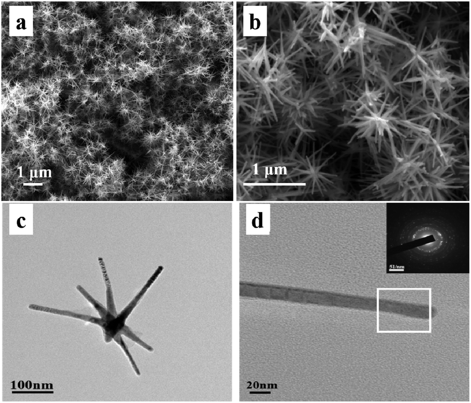 | ||
| Fig. 1 (a) and (b) SEM images, (c) TEM image of pine needle-shaped Co nanocrystals; (d) TEM image and SAED image of individual Co nanorods. | ||
In order to explore the formation mechanism of magnetic Co, Fig. 2 exhibits the SEM images of pine needle-shaped Co nanocrystals under different reaction time periods. It is known that the precursor salt RuCl3 is reduced by 1,2-butanediol to form heterogeneous nanospheres at the beginning of the reaction.27,28 Moreover, it can be observed that the unreacted cobalt laurate nanoparticles aggregate on the surface of these nanospheres. As the reaction progresses, the Ru nuclei begins to be nanocrystallized. When the Ru nuclei with an appropriate size appears, the Co nanoparticles start to reduce and gather on the surface of the Ru nuclei. However, the nanorod structure of Co nanoparticles is not obvious at the initial stage (Fig. 2b). With the further extension of the reaction time, due to the different growth rate of each crystal face of the hexagonal close-packed phase, the growth rate along the c-axis is significantly faster, which makes the nanorod-like structure more obvious and the aspect ratio increases continuously. As a result, the pine needle-shaped Co nanocrystals can be clearly observed (Fig. 2c and d).
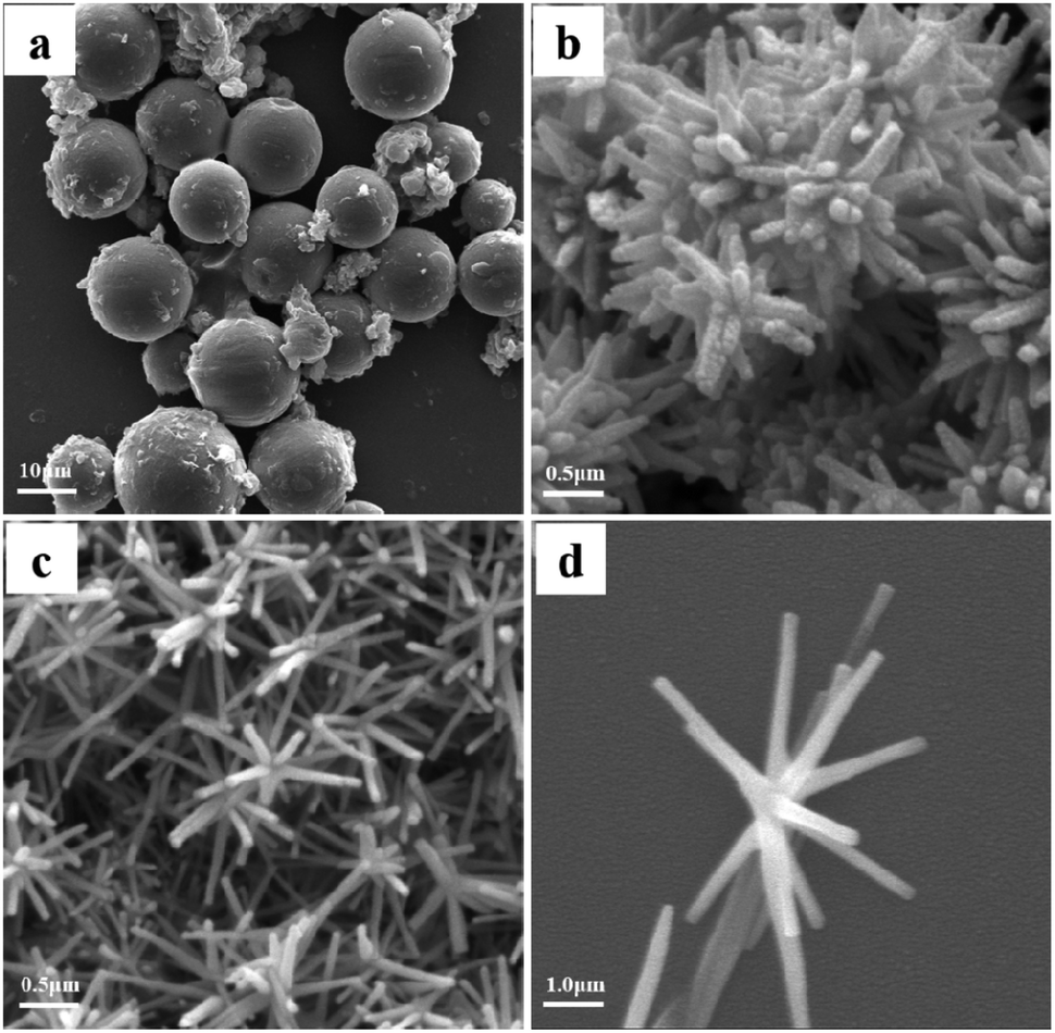 | ||
| Fig. 2 SEM images of Co nanocrystals under different reaction times: (a) 20 min; (b) 40 min; (c) 60 min and (d) 80 min. | ||
To verify the crystal structure of the as-synthesized Co nanocrystals, Fig. S1† demonstrates their XRD pattern. The diffraction peaks at 2θ = 41.7°, 44.78°, 47.6°, 62.7° and 75.9° corresponding to the (100), (002), (101), (102) and (110) planes, which are assigned to the hexagonal close-packed phase of Co (JCPDS no. 05-0727). After compounding with rGO nanosheets, the XRD pattern of rGO/Co nanocomposites is almost the same as that of Co nanocrystals, indicating the addition of rGO has no effect on the crystal structure of the magnetic Co. Moreover, the diffraction peak of GO powder at ∼10° disappears in the XRD pattern of rGO/Co nanocomposites demonstrating that the GO has been reduced effectively (Fig. 3b). From the SEM images of the rGO nanosheets and rGO/Co nanocomposites shown in Fig. 3a and c, the Co nanocrystals can be coated by rGO nanosheets and the pine needle-like morphology still retained. To verify the dispersion of rGO/Co nanocomposites in the PVDF matrix, the cross sectional FESEM images of the rGO/Co/PVDF membrane and EDS elemental mappings of Co and C elements manifest that the rGO/Co nanocomposites were uniformly dispersed into PVDF.
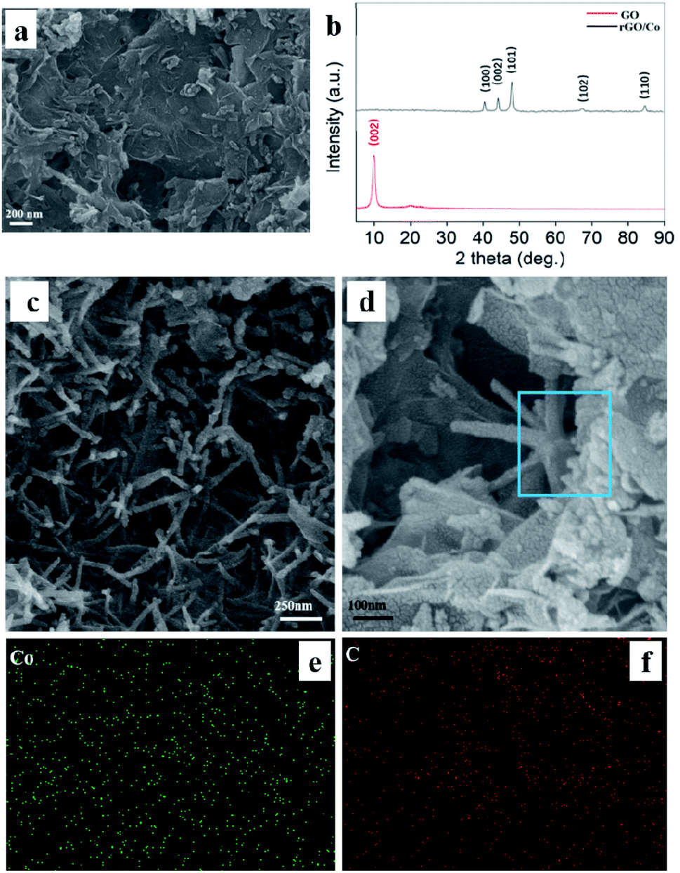 | ||
| Fig. 3 FESEM image of (a) rGO nanosheets and (c) rGO/Co nanocomposites; (b) XRD patterns of GO and rGO/Co nanocomposites; (d) cross sectional FESEM images of rGO/Co/PVDF membrane; EDS elemental mappings of (e) Co and (f) C element. | ||
To evaluate the EM wave absorption efficiency, the reflection loss (RL) values are calculated by the following theoretical formula based on the transmission line theory:29,30
 | (1) |
 | (2) |
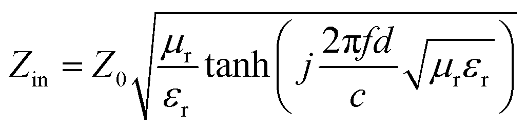
:1, 1:2, 1:3, 1:4, 1:5 and 1:6) at a thickness of 1.8 mm (20 wt%). It can be found that the microwave absorption intensity is closely related with the mass ratios of rGO/Co, the minimum RL value reaches −57.8 dB at 12.43 GHz when the mass ratio of rGO/Co is 1:4. Additionally, the EAB covers the frequency range from 4.2 to 15.5 GHz at 1.5–4.0 mm. For comparison, Fig. 4b and c exhibit the RL curves of rGO/Co/PVDF composites and Co/PVDF composites under a filler amount of 20 wt% at different thicknesses, respectively. It is obvious that the wave absorption intensity and effective absorption bandwidth (EAB) of rGO/Co/PVDF composites are more superior to that of Co/PVDF composites due to the addition of rGO nanosheets. On the other hand, the Co/PVDF composites possess dual-peak absorption compared with rGO/Co/PVDF composites. Fig. 4d indicates that the optimal filler loading is 20 wt% for Co/PVDF composites.
 | ||
| Fig. 4 The RL curves of (a) rGO/Co/PVDF composites under different mass ratios of rGO/Co at a thickness of 1.8 mm and (b) rGO/Co/PVDF composites (rGO/Co = 1:4) within different thicknesses under 20 wt% filler loading; the RL curves of Co/PVDF composites under (c) different thicknesses within 20 wt% filler loading and (d) various filler loadings at 3.7 mm. | ||
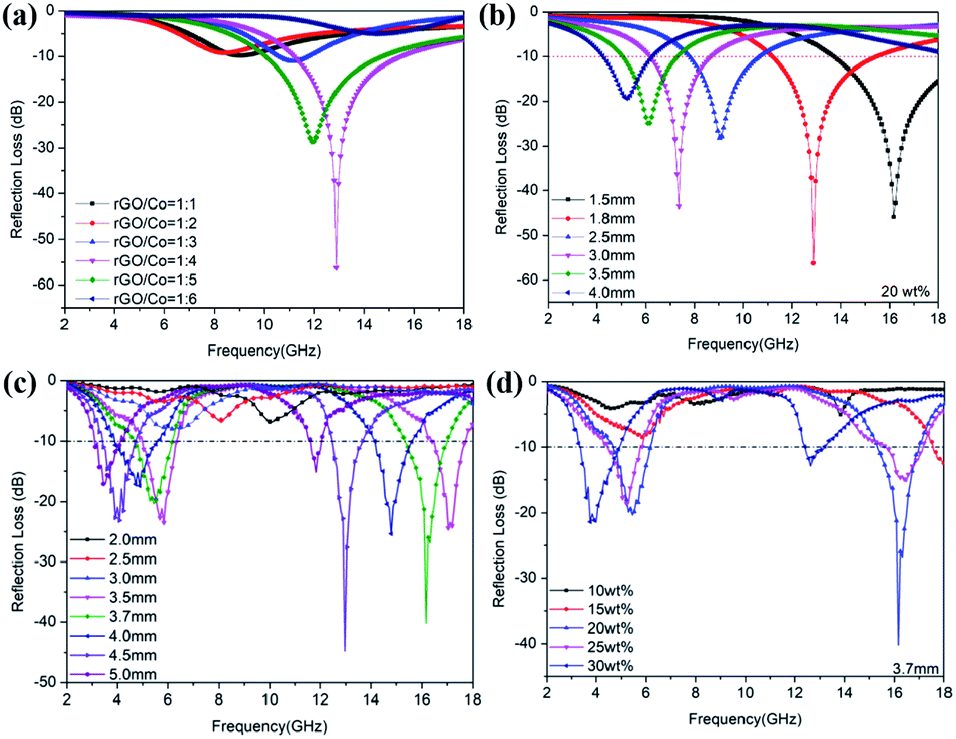
Apart from the mass ratio of rGO/Co, the filler loading and simulation thickness can also influence the microwave attenuation capacity to a large extent. Fig. 5 shows the RL curves of rGO/Co/PVDF composites (rGO/Co = 1:4) at 1.5–5.0 mm within filler loadings of 10 wt%, 15 wt%, 20 wt% and 25 wt%. The results indicate that the filler amount and thickness are able to regulate the microwave attenuation capacity effectively. It is clear that the optimal filler loading is still 20 wt%. Furthermore, it can be summarized by comparing the results of Fig. S2–S6† that the additive amount of rGO nanosheets have obvious influence on the microwave absorbing properties of rGO/Co/PVDF composites. The higher the doping amount of rGO, the smaller the loading amount of rGO/Co with best absorbing performance. Moreover, with the increase in thickness, the absorption peak shifts to the low frequency region due to the one-quarter wavelength theory.31
 | ||
| Fig. 5 The RL values for rGO/Co/PVDF composites (rGO/Co = 1:4) under different filler loadings: (a) 10 wt%; (b) 15 wt%; (c) 20 wt% and (d) 25 wt% within different thicknesses. | ||
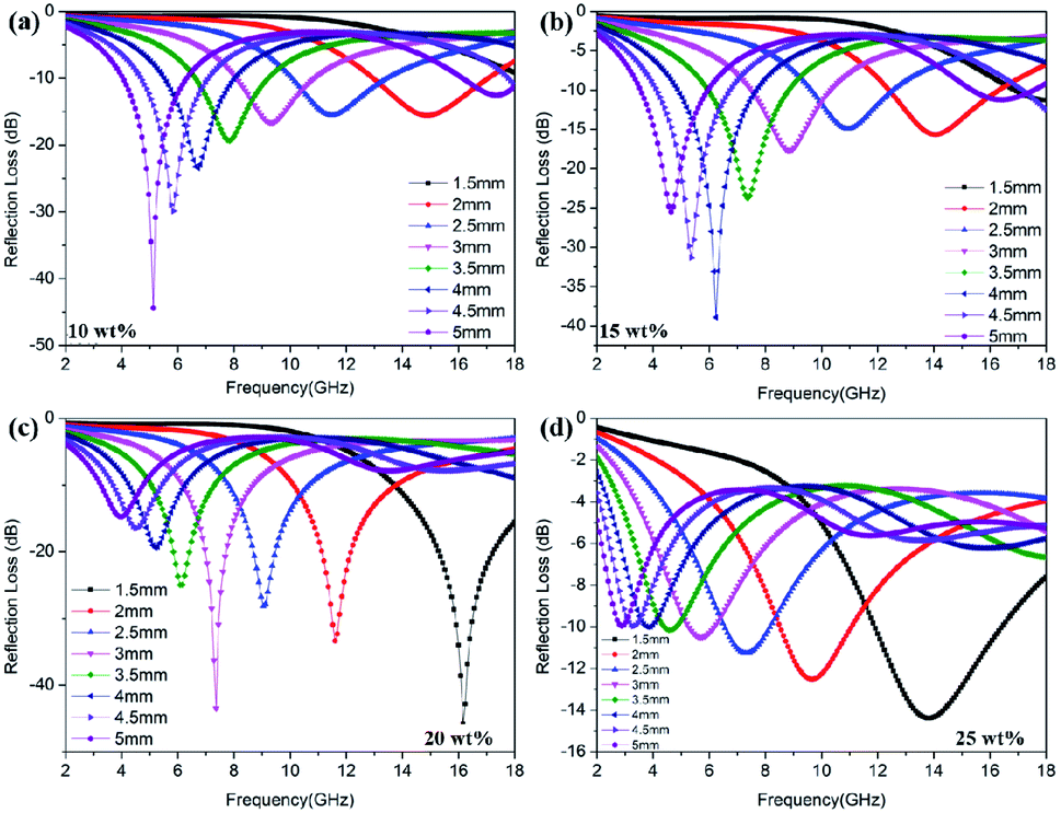
In order to explore the wave absorption mechanism of rGO/Co/PVDF composites, the EM parameters of these samples synthesized under different mass ratios of rGO/Co at the same loading (20 wt%) were investigated and the results are shown in Fig. 6. In general, the ε′ and μ′ represent the storage capability of electric and magnetic energy, respectively, while ε′′ and μ′′ are related to the ability of dissipating the EM energy.32 It is observed that with the increase in the loading ratio of rGO, the ε′ values augment obviously, which proves that rGO could to improve their dielectric performance due to the interfacial polarization effect derived from the pine needle structure and rGO nanosheets. In addition, both of the ε′ and ε′′ values for rGO/Co/PVDF composites increase distinctly with the increase in the filler loading, but they are all larger than that of Co/PVDF composites, indicating that the existence of rGO can improve their dielectric polarization ability and dissipative capacity effectively. However, the addition of rGO did not significantly affect the μ′ and μ′′ values, suggesting that the effects of rGO on the magnetic loss is limited (Fig. 6, S7 and S8†).
 | ||
| Fig. 6 (a) Real part and (b) imaginary part of permittivity, (c) real part and (d) imaginary part of permeability, (e) dielectric loss and (f) magnetic loss of rGO/Co/PVDF composites with different mass ratios of rGO and Co. | ||
In general, the tangent of dielectric loss (tanδε = ε′′/ε′) and magnetic loss (tanδμ = μ′′/μ′) refer to dielectric loss and magnetic loss ability, respectively. In Fig. 6e and f, it is notable that the tan δε values are larger than tan δμ values in 2–18 GHz, demonstrating that the dielectric loss is predominant for rGO/Co/PVDF composites. For Co/PVDF composites, it can be observed that the tanδμ values are larger than tanδε values in 2–8 GHz, while the tanδμ values are smaller than tanδε values in 8–18 GHz. The results show that the magnetic loss is predominant at lower frequency, while the dielectric loss is predominant at higher frequency, because of which the Co/PVDF composites display dual-peak absorption characteristics (Fig. S8e and f†). The dielectric loss mainly arises from the dipole polarization formed by Co nanocrystals and rGO itself, and multiple interfacial polarization among rGO, Co and PVDF. The magnetic loss for magnetic rGO/Co nanocomposites mainly includes ferromagnetic resonance and eddy current effect.33 The eddy current loss is characterized by C0 = μ′′(μ′)−2f−1. If the magnetic loss is attributed to the eddy current loss, C0 will remain constant.34 As shown in Fig. S9,† the C0 values almost remain unchanged from 6 to 18 GHz, demonstrating that the eddy current loss exists in this frequency range.
Briefly, the efficient microwave absorption of the rGO/Co/PVDF composite is caused by simultaneous dielectric and magnetic losses. Fig. 7 displays the possible EM wave absorption mechanisms of rGO/Co/PVDF hybrids. Apart from the dielectric loss derived from dipole orientation polarization and multiple interfacial polarization and magnetic loss caused by ferromagnetic resonance and eddy current loss, the pine needle-like Co nanocrystals provide more reflection and scattering active sites for incident EM waves. On the other hand, this special structure can make full use of the advantages of electron transport and supply a longer current dissipation and conversion channel, which is convenient for further dissipation of EM energy by extending their transmission path.35
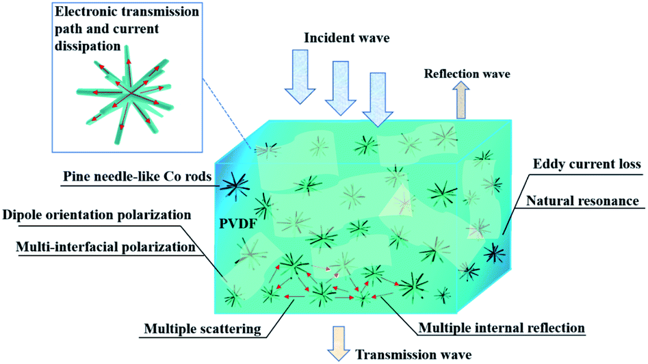 | ||
| Fig. 7 The microwave absorption mechanism of rGO/Co/PVDF composite. | ||
Conclusion
In summary, the pine needle-like Co nanocrystals wrapped with rGO nanosheets have been successfully fabricated via a facile polyol process and ultrasonic blending. The growth mechanism of these pine needle-shaped Co nanocrystals is also investigated by controlling the reaction temperature. It is concluded that the microwave absorption properties of rGO/Co/PVDF composites are closely associated with the mass ratio of rGO/Co, the filler loadings and the simulation thickness. When the mass ratio of rGO/Co is 1:4, the minimum RL value reaches −57.8 dB at 12.43 GHz within the filler loading of 20 wt% (1.8 mm), and the EAB covers the frequency range from 4.2 to 15.5 GHz by tuning the thickness from 1.5 to 4.0 mm. Both the wave absorption intensity and EAB of rGO/Co/PVDF composites are more superior to that of Co/PVDF composites due to the combination of dielectric and magnetic losses. This study provides new research ideas for typical magnetic metal nanomaterials with unique nanostructures for application in the field of microwave absorption, making them candidates for novel EM wave absorbents.
Conflicts of interest
There are no conflicts to declare.Acknowledgements
This work was supported by the National Natural Science Foundation of China (No. 52073010).Notes and references
- J. Liang, J. Chen, H. Shen, K. Hu, B. Zhao and J. Kong, Chem. Mater., 2021, 33, 1789–1798 CrossRef CAS.
- L. Liang, P. Xu, Y. Wang, Y. Shang, J. Ma, F. Su, Y. Feng, C. He, Y. Wang and C. Liu, Chem. Eng. J., 2020, 395, 125209 CrossRef CAS.
- J. Qiao, X. Zhang, C. Liu, L. Lyu, Z. Wang, L. Wu, W. Liu, F. Wang and J. Liu, Composites, Part B, 2020, 200, 108343 CrossRef CAS.
- X. J. Zhang, A. P. Guo, G. S. Wang and P. G. Yin, IET Nanodielectr., 2018, 2, 2–10 CrossRef.
- G. Gou, F. Meng, H. Wang, M. Jiang, W. Wei and Z. Zhou, Nano Res., 2019, 12, 1423–1429 CrossRef CAS.
- S. Wang, D. Li, Y. Zhou and L. Jiang, ACS Nano, 2020, 14, 8634–8645 CrossRef CAS PubMed.
- N. Zhang, Y. Wang, P. Chen and W. Chen, J. Colloid Interface Sci., 2021, 581, 84–95 CrossRef CAS PubMed.
- Z. Song, X. Liu, X. Sun, Y. Li, X. Nie, W. Tang, R. Yu and J. Shui, Carbon, 2019, 151, 36–45 CrossRef CAS.
- I. Shanenkov, A. Sivkov, A. Ivashutenko, V. Zhuravlev, Q. Guo, L. Li, G. Li, G. Wei and W. Han, Phys. Chem. Chem. Phys., 2017, 19, 19975–19983 RSC.
- H. Lv, X. Liang, G. Ji, H. Zhang and Y. Du, ACS Appl. Mater. Interfaces, 2015, 7, 9776–9783 CrossRef CAS PubMed.
- Q. Liu, Q. Cao, X. Zhao, H. Bi, C. Wang, D. S. Wu and R. Che, ACS Appl. Mater. Interfaces, 2015, 7, 4233–4240 CrossRef CAS PubMed.
- X. J. Zhang, G. S. Wang, W. Q. Cao, Y. Z. Wei, J. F. Liang, L. Guo and M. S. Cao, ACS Appl. Mater. Interfaces, 2014, 6, 7471–7478 CrossRef CAS PubMed.
- L. S. Fu, J. T. Jiang, C. Y. Xu and L. Zhen, CrystEngComm, 2012, 14, 6827–6832 RSC.
- G. S. Wang, Y. Wu, Y. Z. Wei, X. J. Zhang, Y. Li, L. D. Li, B. Wen, P. G. Yin, L. Guo and M. S. Cao, ChemPlusChem, 2014, 79, 375–381 CrossRef CAS PubMed.
- C. Zhou, C. Wu and M. Yan, Chem. Eng. J., 2019, 370, 988–996 CrossRef CAS.
- Z. Xiang, Y. Shi, X. Zhu, L. Cai and W. Lu, Nanomicro Lett., 2021, 13, 150 Search PubMed.
- F. Yan, D. Guo, S. Zhang, C. Li, C. Zhu, X. Zhang and Y. Chen, Nanoscale, 2018, 10, 2697–2703 RSC.
- X. Gao, Y. Wang, Q. Wang, X. Wu, W. Zhang, M. Zong and L. Zhang, Ceram. Int., 2019, 45, 3325–3332 CrossRef CAS.
- F. Sun, Q. Liu, Y. Xu, X. Xin, Z. Wang, X. Song, X. Zhao, J. Xu, J. Liu, L. Zhao, P. Zhang and L. Gao, Chem. Eng. J., 2021, 415, 128976 CrossRef CAS.
- G. S. Wang, Y. Y. Wu, X. J. Zhang, Y. Li, L. Guo and M.-S. Cao, J. Mater. Chem. A, 2014, 2, 8644–8651 RSC.
- M. Javid, X. Qu, F. Huang, X. Li, A. Farid, A. Shah, Y. Duan, Z. Zhang, X. Dong and L. Pan, Carbon, 2021, 171, 785–797 CrossRef CAS.
- Y. Hou, L. Cheng, Y. Zhang, Y. Yang, C. Deng, Z. Yang, Q. Chen, P. Wang and L. Zheng, ACS Appl. Mater. Interfaces, 2017, 9, 7265–7271 CrossRef CAS PubMed.
- B. Zhou, M. Su, D. Yang, G. Han, Y. Feng, B. Wang, J. Ma, J. Ma, C. Liu and C. Shen, ACS Appl. Mater. Interfaces, 2020, 12, 40859–40869 CrossRef PubMed.
- L. Liang, G. Han, Y. Li, B. Zhao, B. Zhou, Y. Feng, J. Ma, Y. Wang, R. Zhang and C. Liu, ACS Appl. Mater. Interfaces, 2019, 11, 25399–25409 CrossRef CAS PubMed.
- X. J. Zhang, G. S. Wang, Y. Z. Wei, L. Guo and M. S. Cao, J. Mater. Chem. A, 2013, 1, 12115–12122 RSC.
- X. Luo, G. S. Wang, H. Y. Guo, X. J. Zhang, W. Q. Cao, Y. Z. Wei, L. Guo and M. S. Cao, ChemPlusChem, 2014, 79, 1089–1095 CrossRef CAS.
- K. Gandha, J. Mohapatra and J. P. Liu, J. Magn. Magn. Mater., 2017, 438, 41–45 CrossRef CAS.
- K. Gandha, K. Elkins, N. Poudyal, X. Liu and J. P. Liu, Sci. Rep., 2014, 4, 5345 CrossRef CAS PubMed.
- S. Gao, Y. Zhang, H. Xing and H. Li, Chem. Eng. J., 2020, 387, 124149 CrossRef CAS.
- Y. Qian, H. Wei, J. Dong, Y. Du, X. Fang, W. Zheng, Y. Sun and Z. Jiang, Ceram. Int., 2017, 43, 10757–10762 CrossRef CAS.
- Z. Li, E. Yang, X. Qi, R. Xie, T. Jing, S. Qin, C. Deng and W. Zhong, J. Colloid Interface Sci., 2020, 565, 227–238 CrossRef CAS PubMed.
- X. Zhou, Z. Jia, A. Feng, K. Wang, X. Liu, L. Chen, H. Cao and G. Wu, Compos. Commun., 2020, 21, 100404 CrossRef.
- Y. Wang, X. Li, X. Han, P. Xu, L. Cui, H. Zhao, D. Liu, F. Wang and Y. Du, Chem. Eng. J., 2020, 387, 124159 CrossRef CAS.
- T. Hou, B. Wang, M. Ma, A. Feng, Z. Huang, Y. Zhang, Z. Jia, G. Tan, H. Cao and G. Wu, Composites, Part B, 2020, 180, 107577 CrossRef CAS.
- L. Lyu, F. Wang, J. Qiao, X. Ding, X. Zhang, D. Xu, W. Liu and J. Liu, J. Alloys Compd., 2020, 817, 153309 CrossRef CAS.
Footnotes |
| † Electronic supplementary information (ESI) available. See DOI: 10.1039/d1ra06050c |
| ‡ These authors contributed equally to this work and should be considered co-first authors. |
| This journal is © The Royal Society of Chemistry 2021 |