
 Open Access Article
 This Open Access Article is licensed under a Creative Commons Attribution-Non Commercial 3.0 Unported Licence
Structural designing of Zn2SiO4:Mn nanocrystals by co-doping of alkali metal ions in mesoporous silica channels for enhanced emission efficiency with short decay time†
Neeti Tripathi * and
Tomoko Akai
* and
Tomoko Akai
Nanomaterials Research Institute (NMRI), National Institute of Advanced Industrial Science and Technology (AIST), Kansai Center, 1-8-31 Midorigaoka, Ikeda, Osaka 563-8577, Japan. E-mail: n-tripathi@aist.go.jp
First published on 11th November 2021
Abstract
High purity Zn2SiO4:Mn crystals were synthesized by impregnating a precursor solution into mesoporous silica followed by sintering process. The effects of doping alkali metal ions (Li+, Na+, K+) on the structural, morphological and photoluminescence properties were investigated. Formation of single phase α-Zn2SiO4:Mn crystals was confirmed from X-ray diffraction. The crystal size was significantly decreased from 54 nm to 35 nm with increasing molar concentration of alkali metal ion dopants in Zn2SiO4:Mn. Zn2SiO4:Mn crystals co-doped with alkali metal ions showed stronger emission and faster decay times compared to the un-doped Zn2SiO4:Mn phosphor. The highest emission quantum yields (EQEs) of 68.3% at λexc 254 and 3.8% at λexc 425 nm were obtained for the K+ ion doped samples with Mn2+![[thin space (1/6-em)]](https://www.rsc.org/images/entities/char_2009.gif) :K+ ratio of ∼1:1. With alkali metal ions (Li+, Na+, K+) co-doping, the decay time of Zn2SiO4:Mn crystals was shortened to ∼4 ms, whereas the emission intensity was elevated, with respect to un-doped Zn2SiO4:Mn crystals. Zn2SiO4:Mn crystal growth in silica pores together with selective doping with alkali metal ions paves a way forward to shorten the phosphor response time, without compromising emission efficiency.
:K+ ratio of ∼1:1. With alkali metal ions (Li+, Na+, K+) co-doping, the decay time of Zn2SiO4:Mn crystals was shortened to ∼4 ms, whereas the emission intensity was elevated, with respect to un-doped Zn2SiO4:Mn crystals. Zn2SiO4:Mn crystal growth in silica pores together with selective doping with alkali metal ions paves a way forward to shorten the phosphor response time, without compromising emission efficiency.
Introduction
Manganese doped zinc silicate (Zn2SiO4:Mn) is a well-known green phosphor and has been widely used as a green component for decades in fluorescent lamps and plasma display panels (PDPs).1,2 Nevertheless, recent demonstrations in optical imaging for biological applications have added new value to its applicability.3 Though Zn2SiO4 has several polymorphs including α, β and γ phases, only the α-Zn2SiO4 phase doped with manganese forms a stable structure and shows green emission at ∼527 nm, which is characterized by the transition from the lowest excited state to the ground state i.e., the 4T1 → 6A1 transition. This transition is forbidden according to selection rules, therefore, the decay time of the emission is long.4–7 Additionally, the optimized critical limit of Mn2+ doping concentration is ∼2–5 mol% to achieve a superior performance in the Zn2−xSiO4:xMn matrix and beyond that concentration a quenching effect occurs due to formation of isolated Mn2+–Mn2+ pairs, which deteriorate the emission intensity.4,6As for the synthesis of commercial Zn2SiO4:Mn2+ phosphor, solid state reaction (SSR) have been used, where oxide powders (e.g. ZnO, and MnO) are reacted at high reaction temperatures.8,9 On the other hands, various synthesis methods such as sol–gel, spray drying and planetary ball-milling were applied to prepare precursor of the crystal to control the size and morphology of the phosphor with a hope for obtaining better luminescence properties.10–13 However, these methods are complex process with poor controllability often resulting in the formation of undesired mixed phases.
Nonetheless, synthesis of Zn2SiO4:Mn crystals by using mesoporous silica (MPS) template route has gained considerable attention, as it can facilitate the formation of nanosized crystals at relatively lower temperature with improved emission properties.14,15 Such kind of template assisted, confined growth of nanosized particles is widely adopted, as the size of nanocrystals can be easily controlled by selecting the specific sizes of silica pores.16,17
Another biggest advantage of MPS assisted growth is the uniform distribution of fluorescent ions in to the pores, while keep them isolated from each other. In case of Zn2SiO4:Mn phosphor, though concentration quenching of Mn2+ ions could be minimized using MPS framework, however at the same time, the larger inter-ion distance inevitably leads to longer decay time due to reduced energy exchange between ions.14,18,19 Some reports suggested that doping of metal cations (M2+, M = Mg, Sr, Ca, Ba, Cr) can induce the enhanced photoluminescence (PL) efficiency and shorter decay time simultaneously.20,21 Nonetheless, these metal cations tend to form metal silicate compounds as an impurity phases,20 which might hamper the green emission from the pure Zn2SiO4:Mn phase.
To shorten the decay-time of enhanced luminescence in α-Zn2SiO4:Mn prepared by MPS, we propose to modify crystal structure by doping of alkali metal ions (Li+, Na+, K+). The doping of alkali metal ions help in manipulating the optical transitions of Mn2+ through crystal deformation. The effect combined with uniform distribution of Mn2+ in α-Zn2SiO4:Mn prepared by MPS is expected to produce Zn2SiO4:Mn with superior luminescent properties i.e., stronger emission and shorter decay time. For the synthesis, concentration of Zn2+ and Mn2+ ions were kept fixed whereas, optimization of structure, photoluminescence and decay time were carried out as a function alkali metal ion concentration. A careful optimization of experimental conditions and dopant (Li+, Na+, K+) concentrations allowed us to obtain high photoluminescence quantum yield (PL-QY) and shorter decay time in the range of ∼4–6 ms simultaneously. Moreover, these nanocrystalline phosphor showed comparable PL-QY under 254 nm excitation, higher PL-QY under 425 nm excitation and slightly shorter decay time, compared to the commercial one.
Synthesis of Zn2SiO4:Mn phosphors
For the synthesis of Zn2SiO4:Mn phosphors, Zn(NO3)3, Mn(NO3)2 [all from Wako Chemical Ltd. 99.99%] were used as a starting materials without any further purification. For the doping of alkali metal ions (Li+, Na+, K+), nitrates of respective ions were used to prepare the molar precursor solution in deionized (D.I.) water. Similarly, Zn and Mn precursor solutions were also prepared separately in D. I. water with fixed molality. These molar solutions were mixed together in proportion to the desired molarity to make the total volume of 6 ml. After that, 0.5 g of MPS particles (Sigma-Aldrich, pore size 120 Å, pore volume 1.073 cm3 g−1) were added to this solution. In our samples, molar concentration of Zn(NO3)3 and Mn(NO3)2 were kept fixed to 4.0 M and 0.32 M, whereas dopants (Li+, Na+, K+) molarities were varied from 0.06 M to 0.42 M (i.e., 0.06 M, 0.12 M, 0.18 M, 0.24 M, 0.30 M, 0.36 M, and 0.42 M). The complete synthesis procedure of Zn2SiO4:Mn phosphor is depicted in Fig. 1, where precursor solutions were soaked by the pores of mesoporous silica particles (size ∼ 12 nm, pore volume 1.073 cm3 g−1). The excess amount of precursor solution was then separated out through vacuum filtration process. These soaked and filtered silica particles were then dried in hot air oven at 70 °C, and then subjected to pre-sintering at 550 °C, in air atmosphere. Finally, sintering at temperature 1080 °C, results in the formation of Zn2SiO4:Mn crystals in mesoporous silica matrix. It is expected, that silica will be in excess amount in comparison with the Zn and Mn molarity, as it is playing role of host matrix to grow the Zn2SiO4:Mn crystals inside its pore. Once, the Zn2SiO4:Mn crystals are formed inside the silica pore, it remains intact and showed the properties of Zn2SiO4:Mn phosphor in all aspects, discussed in following section. Elemental mapping of Zn2SiO4:Mn,K crystals by EDX and elemental distribution measured by XPS are shown in the ESI file (Fig. S1 and Table S1),† confirming the excess amount of silica.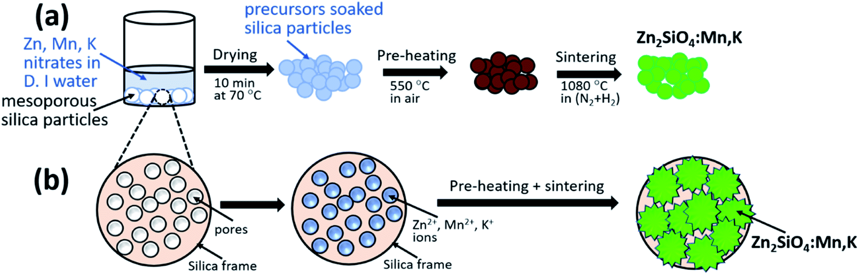 | ||
| Fig. 1 (a) Schematic of the experimental procedure for the synthesize the Zn2SiO4:Mn phosphor (b) extended view of individual silica particle with pores and evolution of Zn2SiO4:Mn,K nanocrystals through reaction of soaked precursor solution into the mesoporous silica frame at 1080 °C. | ||
Results and discussion
XRD patterns of Zn2SiO4:Mn,K samples are shown in Fig. 2. All the diffraction peaks can be indexed to pure willemite structure of Zn2SiO4 and matched well with the single crystal powder XRD22 of α-Zn2SiO4 (Fig. S2†). No XRD peaks from other phases of Zn2SiO4 or impurities were detected, indicating the high purity single phase formation α-Zn2SiO4:Mn,K crystals. Moreover, crystal structure of all K+ ions doped Zn2SiO4:Mn samples remain unchanged, irrespective of the high doping concentration of K+ ions at 0.42 M. However, a gradual decrease in the signal intensity occurred with increasing K+ concentration, suggesting the decrease in crystallite size. A gradual shift towards the higher 2θ up to 0.36 M of K+ concentration and beyond that a shift towards the lower 2θ were observed, as shown in the Fig. 3. In our samples, molar concentration of Zn2+ and Mn2+ ions are kept fixed to 0.40 M and 0.32 M, while molar concentration of K+ ions is varied from 0.06 M to 0.42 M. As the ionic radius of K+ ion (ri = 1.38 Å) is much larger than the Zn2+ (0.74 Å) and Mn2+ (0.80 Å) ions, the excessive doping of K+ ions beyond 0.36 M, resulted in the lattice expansion. Whereas, possible existence of Mn3+ ions23 in to the lattice might causes the initial lattice contraction due to smaller radius of Mn3+ (0.72 Å) ions. Similar trends in XRD peak shifts were also observed for Li+ and Na+ ions doped Zn2SiO4:Mn phosphor (Fig. S3–S6†).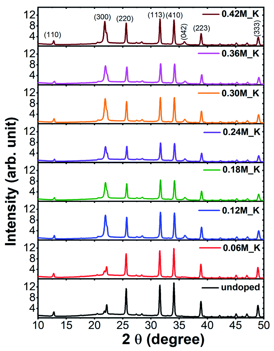 | ||
| Fig. 2 XRD patterns of un-doped and K+ doped Zn2SiO4:Mn phosphor. | ||
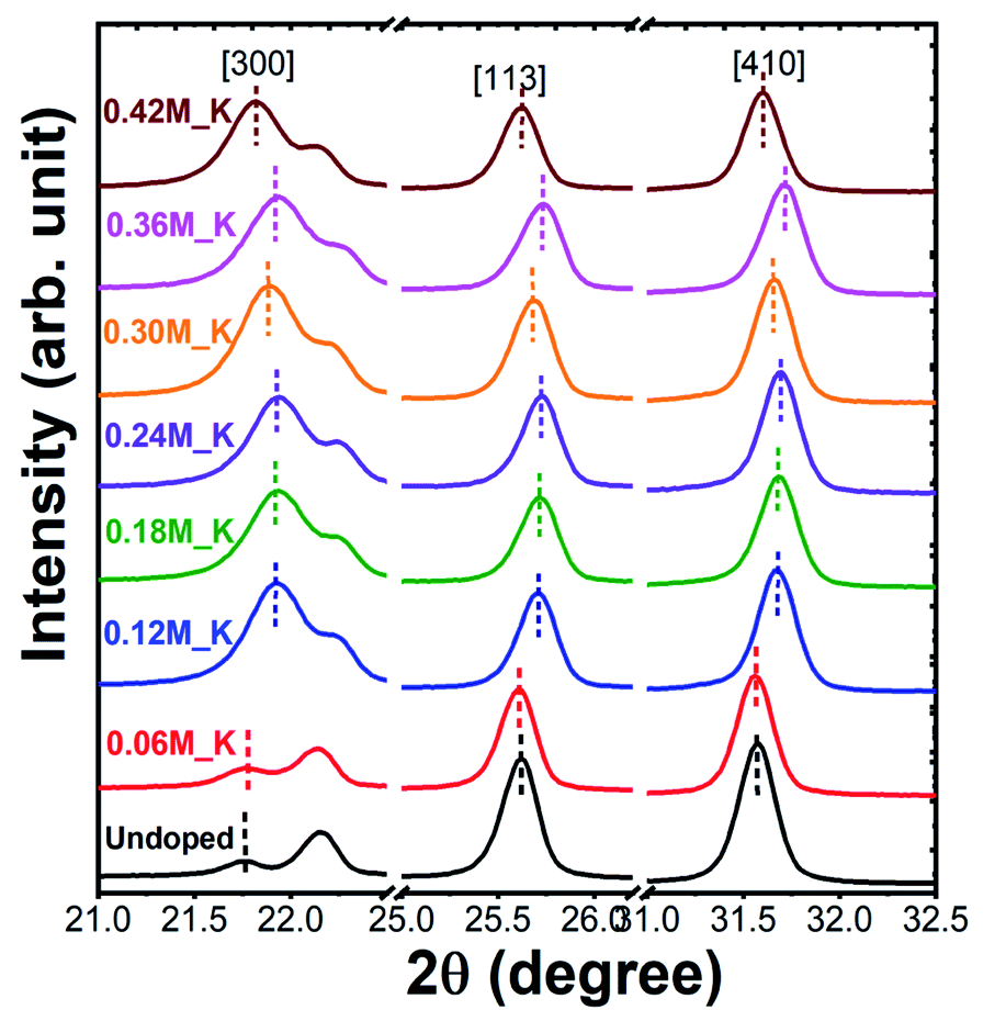 | ||
| Fig. 3 Extended XRD patterns for K+ ions doped Zn2SiO4:Mn phosphor. | ||
We, estimated the grain size by taking finite size approximation only (Scherrer's formula)24 and also due to combined effect of size and strain using Williamson–Hall approach,24,25 given the fact that the large ionic radii of K+ ion can create a significant strain in the system. Williamson–Hall (W–H) approach, is based on the consideration of line broadening due to finite size of coherent scattering region and internal strain due to crystal imperfections and distortions, which is given by,
| βhklcosθ = ε(4sinθ) + 0.94λ/D |
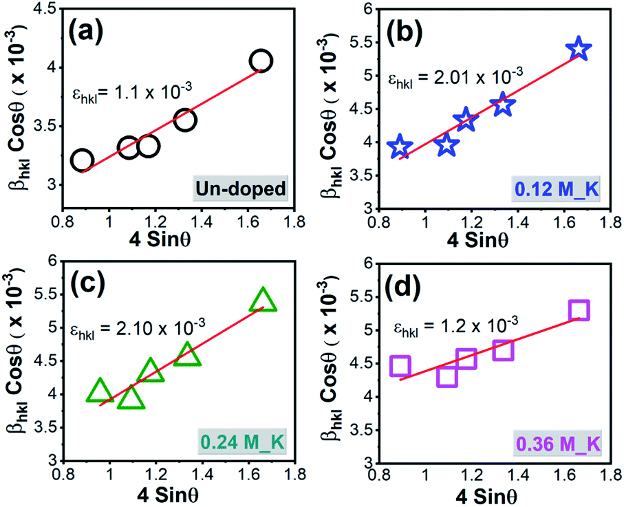 | ||
| Fig. 4 W–H plot for Zn2SiO4:Mn phosphor (a) un-doped and (b) 0.12 M_K+ ions doped (c) 0.24 M_K+ ions doped (d) 0.36 M_K+ ions doped. | ||
| Dopant conc. (M) | Grain size (nm) using | Strain × 10−3 | |
|---|---|---|---|
| Scherrer's formula | W–H plot | ||
| Un-doped | 45.18 | 54.89 | 1.13 |
| 0.06 M_K | 39.30 | 44.83 | 0.85 |
| 0.12 M_K | 36.89 | 45.78 | 1.97 |
| 0.18 M_K | 35.57 | 41.99 | 2.34 |
| 0.24 M_K | 36.13 | 41.74 | 1.82 |
| 0.30 M_K | 34.72 | 38.12 | 2.60 |
| 0.36 M_K | 32.49 | 35.45 | 3.19 |
| 0.42 M_K | 36.19 | 41.73 | 2.45 |
Further confirmation of nanosized crystal formation is done by using scanning transmission electron microscopy (STEM), shown in Fig. S8† suggesting the isolated crystals of the variable sizes from 100–500 nm embedded into the mesoporous silica matrix. The larger size of the crystal is more likely due to the agglomeration of two or more individual crystals. The bright crystals (spot no. 1, 3 and 4) showed similar counts for all the constituting elements such as Zn, Si, O, Mn,K, whereas dark places show the silica-rich regimes (spot no.2).
Surface morphologies of un-doped and doped Zn2SiO4:Mn phosphors were investigated using the scanning electron microscopy (SEM). Fig. 5(a) and (b) showed the SEM images for un-doped Zn2SiO4:Mn phosphor and K+ ions doped Zn2SiO4:Mn phosphor, respectively. No structural changes were observed on the surface of MPS particle for un-doped Zn2SiO4:Mn phosphors, whereas K+ ions doped sample showed the formation of spherical shaped particles, distributed homogenously, all over the surface of MPS particles (inset of Fig. 5(b)). This suggested that K+ ions play an important role in controlling the growth dynamics and can act as fluxes to accelerate the crystal formation process. K+ ions doped Zn2SiO4:Mn phosphor with uniform crystal size and regular spherical-like morphology may exhibit excellent luminescence performance. Similar, effects have been observed for Li+ and Na+ ions doped samples (Fig. S9†). We also used a commercially available green phosphor (standard phosphor), to compare the emission performance of the K+ ions doped Zn2SiO4:Mn phosphor synthesized in this work. Fig. S10,† showed the SEM images of the standard phosphor, suggesting the particle sizes in the range 300–500 nm.
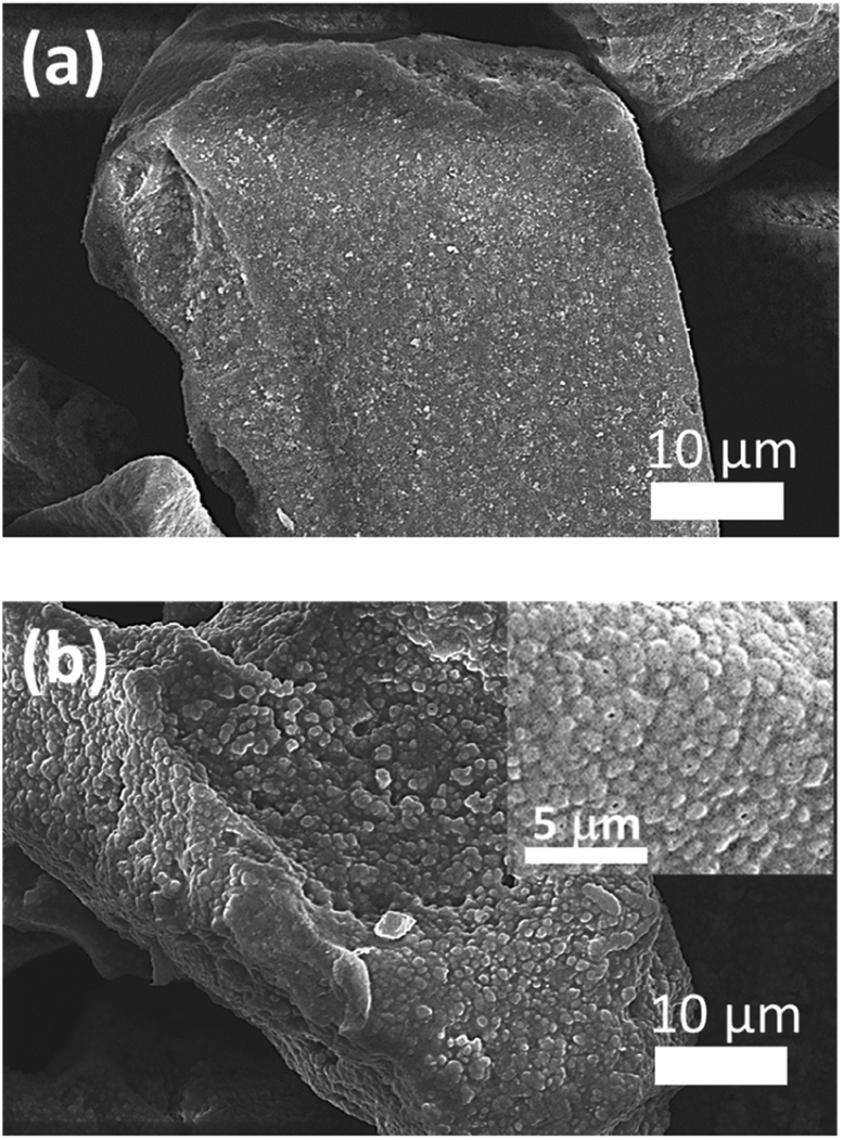 | ||
| Fig. 5 SEM micrographs of (a) un-doped Zn2SiO4:Mn phosphor (b) K+ ions doped Zn2SiO4:Mn phosphor. | ||
Fig. 6(a) compares the PL excitation (PLE) spectra of un-doped pure and K+ ions doped Zn2SiO4:Mn phosphor, monitored at 530 nm emission. An extended view of PLE spectrum in the range 325–525 nm is shown in the inset Fig. 6(b). All the samples show excitation band comprised of 7 major peaks: (i) 255 nm (ii) 330 nm (6A1 → 4T1(4P)), (iii) 358 nm (6A1 → 4E(4D)), (iv) 380 nm (6A1 → 4T2(4D)), (v) 423 nm (6A1 → 4A1(4G)/4E(4G)), (vi) 435 nm (6A1 → 4T2(4G)), and (vii) 470 nm (6A1 → 4T1(4G)) in the direct d–d excitation bands of Mn2+ions.19,26 Excitation band at 255 nm is strong due to an allowed transition and is related to O–Mn2+ charge transfer (CT). We observed a successive enhancement in the intensity of the CT band and six direct excitation bands from 0.06 M to 0.36 M without a variation in their peak positions. K+ dopant concentration of 0.36 M appeared to be an optimum concentration in order to achieve the maximum PLE intensity compared with the standard green phosphor. This enhancement in PLE can be described by the weakening of selection rule on the forbidden intra-transitions of Mn2+ ions in the K+ ions doped samples.27,28 As revealed from XRD, doping of K+ ions, causes lattice distortion in the form of strain. This decrease in lattice symmetry is likely to improve the probability of strong green photoluminescence due to 4T1 → 6A1 forbidden transition of Mn2+ ions. Interestingly, we observed much higher intensity for d–d excitation band for K+ ions doped samples, compared to that of the standard sample (inset Fig. 6(b)). This superior signal for 425 nm excitation band is caused by the relaxation of optical transition by K+ doping and the relaxation of the forbidden transition due to Mn–O orbital intermixing at due to higher Mn2+ concentration.19 Fig. S11† compares the PLE spectra of Li+, Na+ and K+ doped Zn2SiO4:Mn at fixed dopant concentration of 0.30 M. Both K+ and Na+ ions doped Zn2SiO4:Mn sample showed ∼2 times enhancement in the PLE intensity for CT band, compared to the pure and Li+ ions doped Zn2SiO4:Mn samples. Whereas all doped samples showed higher PLE intensity for the direct Mn2+ transitions (inset of Fig. S11†) compared to pure and standard phosphor.
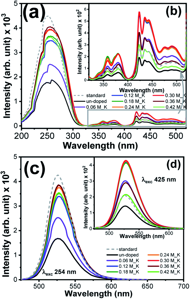 | ||
| Fig. 6 (a) and (b) PL excitation spectra of pure and K+ ions doped Zn2SiO4:Mn phosphor, (c) and (d) PL emission spectra of pure and K+doped Zn2SiO4:Mn phosphor at λexc 254 nm and 425 nm. | ||
Fig. 6(c) and inset Fig. 6(d) showed the photoluminescence (PL) emission spectra of K+ ions doped Zn2SiO4:Mn samples recorded under excitations of 254 nm and 425 nm, respectively. PL spectra of the standard phosphor is also shown together. All the sample showed intense green emission peak centred at 526 nm due to electronic transition from 4T1 to 6A1 states. When K+ ions are introduced in to the Zn2SiO4:Mn matrix, the PL emission intensity increased and reaches to maximum at molar concentration 0.36 M after that start deteriorating. We also observed a noticeable “red shift” in the emission peak for the K+ doping concentration > 0.06 M. Literature revealed19,26,29,30 that in Zn2SiO4:Mn phosphor Mn2+ ions occupies non-equivalent Zn sites viz., Zn(1) position and Zn(2) position. As a result, two closely spaced luminescence peaks Mn2+/Zn(1) (∼540 nm) and Mn2+/Zn(2) (∼526 nm) appeared in the emission spectra and merge in to one broad asymmetric peak cantered at ∼527 nm. Fig. 7(a) and (b) showed the Gaussian fitting of the photoluminescence peak for un-doped and 0.36 M, K+ doped Zn2SiO4:Mn samples, respectively. We observed two emission bands at 523.16 nm and 539.41 nm for un-doped samples, which shifted to 525.56 nm and 541.20 nm, respectively after doping with K+ ions (0.30 M). This peak shift of 2.4 nm, is ascribed to the changes in the crystal filed parameters induced by K+ ion doping. Further, the percentage contribution of Mn2+/Zn(1) and Mn2+/Zn(2) was estimated from the Gaussian peak areas of respective emission bands. We found 45.95% contribution of the Mn2+/Zn(2) in un-doped Zn2SiO4:Mn sample, which increased to 52.60% in the K+ doped Zn2SiO4:Mn sample. Therefore, brighter emission in K+ ions doped Zn2SiO4:Mn is attributed to the higher occupancy of Mn2+/Zn(2) sites, which are responsible for green emission at 526 nm. As an effect of K+ ion co-doping, sub-lattice structure around the Mn2+ luminescent center ions is modified, which influences the spin–orbit coupling and crystal field of Mn2+ ions, causing the observed changes. Comparison of emission spectra of Li+, and Na+ ions doped Zn2SiO4:Mn crystals is shown in the Fig. S12(a) and (b).† Fig. S13† showed the dependence of PL intensities on the dopant molar concentration, which suggest that PL-intensities approach the plateau regime after 0.24 M dopant concentration.
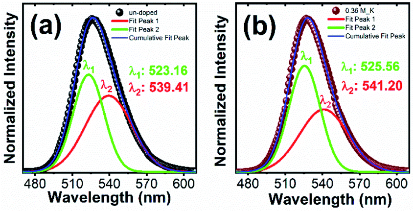 | ||
| Fig. 7 Gaussian fitting of PL emission spectrum of Zn2SiO4:Mn phosphor excited at 254 nm (a) un-doped and (b) K+ ions doped (0.36 M). | ||
Fig. 8(a) showed the decay profiles for un-doped and K+ ions doped Zn2SiO4:Mn samples under 254 nm excitation for 526 nm emission. Decay profiles of Li+ and Na+ ions doped phosphors are shown in the Fig. S14(a) and (b),† respectively. To estimate the respective decay times, all the decay curve can be well fitted by the double exponential function,2,31
| I(t) = A1exp(−t/τ1) + A2exp(−t/τ2) |
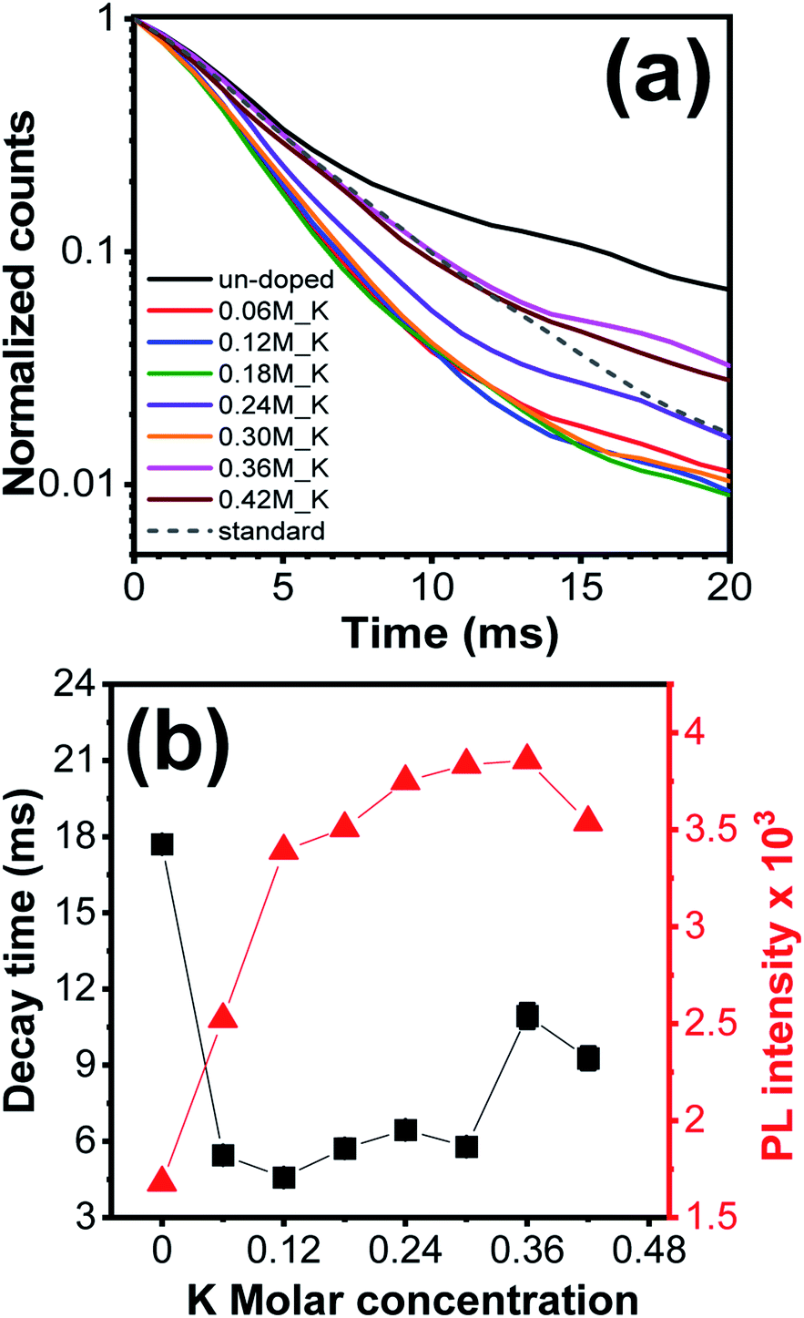 | ||
| Fig. 8 (a) Decay time profiles of K+ ions doped Zn2SiO4:Mn phosphor (b) graph between decay time and PL emission intensity (λexc 254 nm) as a function of K+ ions molar concentration. | ||
To quantify the emission performance, external quantum yields (EQE) of un-doped, 0.36 M K+ ions doped and standard phosphor were measured under excitation wavelengths of 254 nm and 425 nm, given in Table 2. Typical CIE color coordinates (Fig. S18†) of 0.36 M K+ ions doped Zn2SiO4:Mn phosphor are found to be (0.245, 0.697) under 254 nm excitation, in accordance with the commercial standard phosphor. It is noteworthy that our K+ ions doped Zn2SiO4:Mn samples showed a high stability over the time span of several years and maintain the consistent emission properties, compare to the standard phosphor (Fig. S19†).
| Sample | EQE @ 254 nm | EQE @ 425 nm | CIE index | |
|---|---|---|---|---|
| (X) | (Y) | |||
| Un-doped | 64.1% | 0.5% | 0.257 | 0.685 |
| K+ ion doped | 68.3% | 3.8% | 0.245 | 0.697 |
| Standard | 69.8% | 2.7% | 0.245 | 0.700 |
Conclusions
High purity luminescent α-Zn2SiO4:Mn phosphors were synthesized by simple solution impregnation method using disordered mesoporous silica and effects of alkali metal ions (Li+, Na+, K+) co-doping were investigated. In one hand mesoporous silica network provides controlled growth of Zn2SiO4:Mn crystals and homogenous distribution of Mn2+ ions emission, on the other hand doping of alkali metal ions improves the occupancy rate at of Mn2+ ions at Zn(2) position ensuring the stronger green emission at 526 nm. Moreover, co-doping of alkali metal ions helps in improving the exchange interaction between Mn2+ ions, thus shortening the decay time of Zn2SiO4:Mn crystals.Conflicts of interest
There are no conflicts to declare.Notes and references
- Y. Li, S. Qi, P. Li and Z. Wang, RSC Adv., 2017, 7, 38318 RSC.
- A. Morell and N. Elkhiati, J. Electrochem. Soc., 1993, 140, 2019 CrossRef CAS.
- B. Zheng, Y. Bai, H. Chen, H. Pan, W. Ji, X. Gong, X. Wu, H. Wang and J. Chang, ACS Appl. Mater. Interfaces, 2018, 10, 19514 CrossRef CAS PubMed.
- K. S. Sohn, B. Cho and H. D. Park, J. Am. Ceram. Soc., 1999, 82, 2779 CrossRef CAS.
- C. Wang, J. Wang, J. Jiang, S. Xin and G. Zhu, J. Alloys Compd., 2020, 814, 152340 CrossRef CAS.
- C.-C. Diao, C.-F. Yang, R. L. Wang, J. J. Lin and M. Y. Fu, J. Lumin., 2011, 131, 915 CrossRef CAS.
- Y. C. Kang and H. D. Park, Appl. Phys. A, 2003, 77, 529 CrossRef CAS.
- P. V. Ramakrishna, D. B. R. K. Murthy, D. L. Sastry and K. Samatha, Spectrochim. Acta, Part A, 2014, 129, 274 CrossRef CAS PubMed.
- E. van der Kolk, P. Dorenbos, C. W. E. van Eijk, H. Bechtel, T. JuK stel, H. Nikol, C. R. Ronda and D. U. Wiechert, J. Lumin., 2000, 87–89, 1246 CrossRef CAS.
- B. C. Babu, B. V. Rao, M. Ravi and S. Babu, J. Mol. Struct., 2017, 1127, 6 CrossRef.
- J. S. Cho, S. M. Lee, K. Y. Jung and Y. C. Kang, RSC Adv., 2014, 4, 43606 RSC.
- L. T. T. Vien, N. Tua, T. T. Phuong, N. T. Tuan, N. V. Quang, H. Van Buia, A.-T. Duong, D. Q. Trung and P. T. Huy, J. Lumin., 2019, 215, 116612 CrossRef CAS.
- S. Jacob, B. M. Nagabhushana and Chikkahanumantharayappa, Nano-Struct. Nano-Objects, 2019, 19, 100363 CrossRef CAS.
- Q. S. Lu, P. Wang and J. Li, Mater. Res. Bull., 2011, 46, 791 CrossRef CAS.
- Z. Li, H. Zhang and H. Fu, J. Lumin., 2013, 135, 79 CrossRef CAS.
- V. Malgras, S. Tominaka, J. W. Ryan, J. Henzie, T. Takei, K. Ohara and Y. Yamauchi, J. Am. Chem. Soc., 2016, 138, 13874 CrossRef CAS PubMed.
- N. Tripathi, M. Yamashita and T. Akai, J. Mater. Chem. C, 2014, 2, 622 RSC.
- L. Xiong, J. Shi, J. Gu, L. Li, W. Huang, J. Gao and M. Ruan, J. Phys. Chem. B, 2005, 109, 731 CrossRef CAS PubMed.
- K. W. Park, H. S. Lim, S. W. Park, G. Deressa and J. S. Kim, Chem. Phys. Lett., 2015, 636, 141 CrossRef CAS.
- K.-S. Sohn, B. Cho, H. Chang and H. D. Par, J. Electrochem. Soc., 1999, 146(6), 2353 CrossRef CAS.
- X. Yu and Y. Wang, J. Alloys Compd., 2010, 497, 290 CrossRef CAS.
- JCPDS #37-1485 and RRUFF ID: R100109.9.
- T. I. Krasnenko, A. N. Enyashin, N. A. Zaitseva, R. F. Samigullina, A. P. Tyutyunnik, I. V. Baklanova, M. V. Rotermel and T. A. Onufrieva, J. Alloys Compd., 2020, 820, 153129 CrossRef CAS.
- C. F. Holder and R. E. Schaak, ACS Nano, 2019, 13(7), 7359 CrossRef CAS PubMed.
- P. Bindu and S. Thomas, J. Theor. Appl. Phys., 2014, 8, 123 CrossRef.
- M. K. Kretov, I. M. Iskandarova, B. V. Potapkin, A. V. Scherbinin, A. M. Srivastava and N. F. Stepanov, J. Lumin., 2012, 132, 2143 CrossRef CAS.
- Y. Hu, J.-P. Yang and J.-S. Liu, Luminescence, 2012, 437–440 CrossRef PubMed.
- Y. Zhai, Y. Han, W. Zhang, Y. Yin, X. Zhao, J. Wang and X. Liu, J. Alloys Compd., 2016, 688, 241 CrossRef CAS.
- A. L. Gomes, R. Lang, E. Armelin, C. Aleman and J. S. De Carvalho Campos, J. Mater. Chem. C, 2014, 2, 2502 RSC.
- Y. Hao and Y.-H. Wang, J. Alloys Compd., 2009, 470, 565 CrossRef CAS.
- Z. Wei, Z. Wang, W. R. T. Tait, M. Pokhrel, Y. Mao, J. Liu, L. Zhang, W. Wang and L. Sun, J. Mater. Sci., 2018, 53, 1824 CrossRef CAS.
Footnote |
| † Electronic supplementary information (ESI) available: Characterization details, EDX, XRD, SEM, STEM, PL spectrum, and decay time profiles. See DOI: 10.1039/d1ra05515a |
| This journal is © The Royal Society of Chemistry 2021 |