 Open Access Article
Benchtop X-ray fluorescence imaging as a tool to study gold nanoparticle penetration in 3D cancer spheroids
Pedro Pedrosaa,
Pedro V. Baptista a,
Alexandra R. Fernandes
 a and
Mauro Guerra
 *b
*b
aUCIBIO, Departamento de Ciências da Vida, Faculdade de Ciências e Tecnologia, Universidade NOVA de Lisboa, 2892-516, Caparica, Portugal. E-mail: pmvb@fct.unl.pt
bLaboratory of Instrumentation, Biomedical Engineering and Radiation Physics (LIBPhys-UNL), Department of Physics, NOVA School of Science and Technology, NOVA University Lisbon, 2829-516, Caparica, Portugal. E-mail: mguerra@fct.unl.pt
First published on 2nd August 2021
Abstract
The use of nanomaterials to improve medical diagnostics and therapeutics has been rapidly increasing. Among these materials are gold nanoparticles, which can be functionalized to target specific cells, acting as nanovectors for drug delivery, enhanced contrast agents as well as other targeted therapies. Au nanoparticles are very useful as they selectively accumulate in tumour sites due to the enhanced permeability-retention effect. There is however little information about the spatial distribution of the nanoparticles within tumours, which might hinder efficient therapies. In this study, X-ray fluorescence was used to investigate the diffusion of gold nanoparticles in cancer cell spheroids mimicking true tumour growth. Functionalization of the nanoparticles has the effect of allowing better diffusion into and out of the spheroid, while those nanoparticles that are only partially covered rapidly formed aggregates. This clustering led to size exclusion during transport within the tumour, changing its distribution profile while greatly increasing the nanoparticle concentration.
1 Introduction
Nanomaterials hold great promise to revolutionize current therapeutic strategies due to their unique physical-chemical properties that allow for innovative therapeutic and imaging approaches (e.g. photothermy, enhanced contrast agents), and improved solutions for drug delivery systems.1 In the past decades, increasing efforts to develop better-targeted therapies have led to the development of nanoscale formulations capable of improving drug distribution to the designated biological niche, many of which are progressing towards clinical trials.2 One such example is Caelyx, a poly(ethylene glycol)ated (PEGylated) liposomal formulation of Doxorubicin.2 Nanovectorization offers advantages, such as the possibility to target delivery towards selective tumour accumulation, reducing side effects when compared with to the free drug. This is particularly true for nanoparticles (NP), which have been demonstrated to accumulate at tumour sites due to the enhanced permeability retention effect.3 However, this passive targeting might be less effective in non-vascularized tumours. In such cases, the capacity of the particulates to penetrate through the tumour extracellular matrix (ECM) plays a key role in their effectiveness.3,4 The ECM is a mesh of collagen proteoglycans, glycosaminoglycans forming a viscous and negatively charged barrier, bathed by an extracellular fluid.5 These components are believed to hinder the diffusion of molecules to the core of the tumour. There is limited information in the literature about how ECM influences nanoparticle penetration into tumours.6–9 This is partially due to the fact that most studies rely on complex animal models, especially human tumour xenografts. These models are expensive, time-consuming, and have been raising more ethical concerns. As such, in vitro 3D cell models have been gaining popularity as a means to bridge the gap between standard cell culture and the 3D environment, closer to the in vivo.10–13 These models can recapitulate the tumour microenvironment, forming proliferative gradients, hypoxia, and necrosis. However, few studies employ tumour spheroids to understand NP diffusion in tumours.13,14Micro X-ray fluorescence (μ-XRF) imaging is an interesting tool to investigate the elemental distribution within biological tissues due to their versatility and low cost of operation. In the last decade there has been a rise in the use of XRF facilities to investigate toxic metals concentration distribution in biological tissues such as plants15–17 and animals,18–20 among which are human tissues.21–23 Due to the difficulty in access to large facilities such as synchrotrons and free electron lasers, researchers started moving towards the use of bench-top micro-XRF spectrometers to perform hyperspectral images of elemental distribution in tissues previously exposed to contaminants.24 There is however a scarcity of papers in the literature regarding the use of bench-top μ-XRF imaging to study the distribution of nanoparticles in human tissues, especially tumours.24,25 In this study, we have used micro X-ray fluorescence (μ-XRF) to study the penetration of AuNPs into a cancer cell spheroid. We used two percentages of PEG functionalization on AuNPs (30% and 100% coverage) to show the different patterns in spheroid accumulation of both particles. Our ultimate goal is to show that bench-top μ-XRF is a suitable tool to study the penetration of nanomaterials in cell spheroids.
2 Materials and methods
2.1 Sample preparation
AuNP were characterized by ultraviolet-visible (UV-vis) absorption spectroscopy, dynamic light scattering (DLS), Zeta potential and transmission electron microscopy (TEM). UV-visible absorption spectra were recorded at room temperature on a UV-vis spectrophotometer in the range 400–800 nm with 1 cm path quartz Suprasil™ cuvettes. Nanoparticles' hydrodynamic diameter and Z-potential was determined by DLS resorting to a Nanoparticle Analyzer SZ-100 at 25 °C, with a scattering angle of 90°. The AuNP formulations were diluted in MilliQ water to a final concentration of 2 nM prior to analysis. A total of three measurements were performed for each sample. For TEM analysis, AuNP were prepared by depositing 10 μL of the gold colloidal solution on carbon copper grids, washing twice with Milli-Q water, and air dried. TEM results showed a bare AuNP diameter of 13.6 ± 1.8 nm, while the corresponding DLS diameter was of 15.3 ± 0.2 nm.
Polyethylene glycol (PEG) is commonly conveyed in nanoparticles to enhance their stability, confer functional groups and increase their biocompatibility. In general, PEG is attached to AuNP via a thiol group. Au has high affinity to thiol, forming a quasi-valent bond. In this case, an AuNP solution (10 nM) was incubated with 0.028% (w/v) SDS, and PEG 0.003 mg mL−1 (AuNP@PEG30%) or 0.01 mg mL−1 (AuNP@PEG100%) for a period of 16 h under agitation at room temperature. The excess of PEG chains and SDS was removed by washing the AuNPs twice at 14![[thin space (1/6-em)]](https://www.rsc.org/images/entities/char_2009.gif) 000×g for 30 min at 4 °C. The average diameter of the AuNP after functionalization were of 16.4 ± 1.2 nm and 16.8 ± 1.1 nm for the AuNP@PEG30% and AuNP@PEG100%, respectively. AuNP concentration was calculated using the mass of a 13.6 nm diameter gold sphere ε = 2.33 × 10⁸ M−1 cm−1.
000×g for 30 min at 4 °C. The average diameter of the AuNP after functionalization were of 16.4 ± 1.2 nm and 16.8 ± 1.1 nm for the AuNP@PEG30% and AuNP@PEG100%, respectively. AuNP concentration was calculated using the mass of a 13.6 nm diameter gold sphere ε = 2.33 × 10⁸ M−1 cm−1.
2.2 μ-EDXRF measurements
All of the X-ray fluorescence measurements were made using the micro-energy dispersive X-ray fluorescence (μ-EDXRF) system (M4 Tornado™, Bruker, Germany). This commercial spectrometer consists of an air-cooled micro-focus side window a Rh-anode X-ray tube, powered by a low-power HV generator. The system features poly-capillary X-ray optics, that allow a beam spot size of around 22 μm for Rh Kα.17 In all of the measurements, the X-ray generator was operated at 50 kV and 600 μA with a combination of 100 μm Al, 50 μm Ti and 25 μm Cu filters, whose goal was to enhance the signal-to-background ratio around the L-lines of the Au nanoparticles. Detection of the fluorescence radiation is performed by an energy-dispersive silicon drift detector, XFlash™, with a 30 mm2 sensitive area and an energy resolution of 142 eV for Mn Kα.Because in this work we are dealing with biological samples, and one of this work's goals is to approximate the experimental conditions to those in vivo, measurements were taken at atmospheric pressure, in air, immediately after the sample preparation, in order to maintain the sample properties, namely the hydration level. The maps of the 3D cell cultures were performed with a pixel spacing of 15 μm, with a measuring time of 10 ms per pixel, in order to increase statistical significance of the elemental maps. The final images were created with the built-in software from the M4 Tornado™, ESPRIT.
3 Experimental procedure
3.1 Quantification calibration
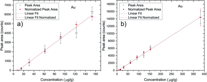
In order to quantify the penetration processes of AuNPs inside the cell aggregates one has to make a correspondence between the detector counts in a given region of the 2D X-ray fluorescence map and the actual concentration of the elements within the sample. This can be achieved through a calibration of the experimental setup through the use of a set of Standard Reference Materials (SRM). Due to the fact that there are no commercial SRM for the typology of the samples under investigation in this work, there was a need to develop some standards for this purpose. Due to the similarity in X-ray absorption coefficients between the cells and agarose gel, the quantification calibration was performed using a set of AuNP spiked agarose samples described in Section 2.1. Each sample was measured 3 times in different locations at 50 kV and 600 μA with the same combination of filters that were later used in the maps of the 3D cell cultures in order to correctly quantify the AuNPs within the cell aggregates. All of the point measurements were acquired during 200 seconds. In Fig. 1 the plot of the peak area as a function of the nominal elemental concentration of the reference samples is presented ((a) is the curve excluding the 25 nM data point and (b) is the full data set). As can be seen, the quantification curves for both the raw and normalized peak areas are very similar, with the normalized case being only slightly better (R2 of 0.99754 versus 0.99467). The quantification curve for the normalized case (full region (b)) results in the expression| c = (0.02586 ± 0.0005) × PA + (5.4 ± 2.9), | (1) |
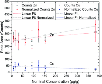
In order to perform a quality assessment of the calibration curve we have normalized each Au peak area to the scattering Rh peak area from the anode of the X-ray tube. This scattering intensity is correlated to physical properties of the sample such as the effective atomic number and density, which are similar in all of the prepared agarose slices. The only factors that could change between measurements are the flux of X-ray photons from the tube or a slight misalignment of the beam with the sample. These two factors would influence in the same way both the fluorescence radiation from the elements of interest and the scattering x rays, thus this normalization allows us to effectively get rid of the influence of these external factors. Another way to check the quality of the standard agarose samples and their corresponding measurements is by checking the peak areas of the elements that are part of the agarose matrix and that should not change with the Au concentration from the spiking procedure. Zn and Cu are present in both the agarose matrix and in the water that was used to prepare the samples. Fig. 2 shows the integrated peak areas of Zn and Cu Kα lines and the areas that were obtained after normalizing to the Rh scattering X-ray lines. Since the cell spheroids were initially bathed in a 10 nM AuNP solution, it was not expected that the measured Au concentration in the cell cultures exceeded that value. However, besides having made a set of samples in the range of 0.5 to 10 nM, a standard sample with 25 nM AuNP concentration was also manufactured. Looking into Fig. 2 we can see that the high concentration agarose sample features a peak area which is around 15–25% higher than the average of the other data points. This might be due to the fact that the initial AuNP solution had a concentration of only 13 nM, and thus the amount of solution that was added to the agarose to make a 25 nM sample was much higher than in the other samples. This solution might have a Zn content that was slightly higher than the water that was used to make the agarose matrix. Another possibility, which is more likely, has to do with the secondary excitation of the Zn atoms in the water by the Lα1,2 X-rays of Au whose line energies are 9713.44(34) eV and 9628.05(33) eV, just above the Zn K-shell ionization threshold of 9660.755(30) eV.29 In this way, the increase in the number of Au atoms in the samples would increase the Zn peak areas due to the high cross section for ionization of Zn from the Lα1,2 characteristic X-rays of Au, with this increase not being related to the true concentration of Zn in the samples. Taking into account all of the data points, the obtained slopes for the Au X-ray counts as a function of the nominal concentration were, for Zn; 0.14 ± 0.05 and 0.31 ± 0.11, respectively for the raw and normalized data set, while for Cu the slopes were; −0.054 ± 0.042 and −0.056 ± 0.038, respectively for raw and normalized data. If we only take into account the lower mass fraction values, for which we expect the Au concentration inside the spheroids to be low enough not to enhance the Zn signal through secondary ionization, the slopes are much more close to zero, as expected. In fact, the obtained slopes were, for Zn; 0.057 ± 0.114 and 0.130 ± 0.250, respectively for the raw and normalized data set, while for Cu the slopes were; −0.041 ± 0.101 and −0.041 ± 0.090, respectively for raw and normalized data. As can be seen from the fitting results of the low concentration range, the slopes are consistent with zero which means that the spiking procedure did not artificially change the concentration of these elements except for the 25 nM sample for the reasons described above. However, as stated before, if the range of the concentration of Au measured in this work is within the 0.5–10 nM range, the calibration curve should provide an excellent method for assessing the true Au mass fraction.
3.2 Lower quantification limits
The sets of developed agarose reference samples also provide us with a very good way to measure the lower quantification limits (LQL) of the NP X-ray signal. In order to find the LQL, we use the standard formula
 | (2) |
| Nominal concentration (μg g−1) | Np | LQL | |
|---|---|---|---|
| 3.83 ± 0.80 | 80 ± 30 | 11.9 ± 0.4 | 5.4 ± 1.6 |
| 7.65 ± 0.80 | 196 ± 13 | 11.3 ± 0.2 | 4.3 ± 0.4 |
| 15.31 ± 0.82 | 350 ± 90 | 11.7 ± 0.4 | 5.0 ± 1.3 |
| 38.27 ± 0.92 | 1040 ± 100 | 13.0 ± 0.4 | 4.7 ± 0.5 |
| 76.54 ± 1.22 | 1580 ± 90 | 13.1 ± 0.4 | 6.2 ± 0.5 |
| 114.81 ± 1.60 | 2730 ± 160 | 12.6 ± 0.6 | 6.9 ± 0.6 |
| Weighted average | 5.3 ± 0.5 |
The uncertainty associated with the detection limit calculation was obtained through error propagation, using the quantification uncertainties and the peak fitting uncertainties as well as the statistical variation between the three measurements of the same sample. As can be seen, the difference between the obtained LQL results from eqn (2) and from eqn (1) is less than 2%, once again showcasing the robustness of the method.
4 Results and discussion
4.1 Quantification of 2 dimensional maps
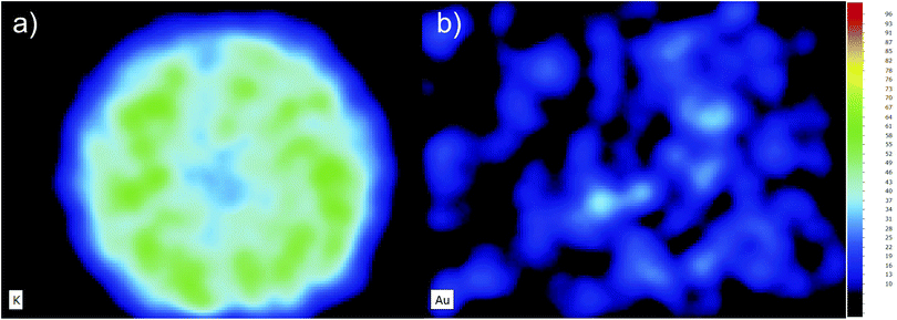
All of the map's quantification was performed by normalizing the acquisition time of a given region of pixels to the same time as the point spectra (200 s). In this way, the total counts obtained in any given region of the maps are consistent with the quantification coefficients calculated from Fig. 1. The use of a normalized curve that takes into account the scattered radiation from the X-ray tube makes it even possible to quantify regions of the map without correcting for the acquisition time. This is possible because both the X-ray line intensity of the element of interest and the scattering lines scale linearly with the acquisition time. Nevertheless, because each pixel in the map has a measuring time of only 10 ms, which is not enough to get good statistics for single pixel spectra deconvolution, we cannot obtain quantification information with high lateral resolution. This means that the 2D intensity maps reflect the number of counts of a given X-ray line and its corresponding background, for each pixel, rather than the element concentration as a function of its position. One drawback of this effect is that the number of counts is slightly biased towards the background radiation which is a function of the density of the sample. This means that regions of the map which feature higher density will also present higher counts in the elemental map, regardless of the element being present or not. However, it will only be a problem when trying to interpret images from samples with elemental concentrations very close to the detection limit of the technique.30 In Fig. 3, a 2D map of the potassium (a) and gold (b) content of a cell spheroid is presented. Note that one could be misled into thinking that there is some gold distributed, somewhat evenly, throughout the spheroid, although the quantitative analysis of the Au concentration results in values that are far below the lower detection limit shown in Table 1. What we are seeing is just the background noise due to scattering from the X-ray tube, which should be fairly homogeneous if there are no holes within the cell aggregate. This effect is even more striking when compared to the K elemental map, (a), as K is part of the cell matrix.4.2 Elemental imaging and quantification of cell spheroids
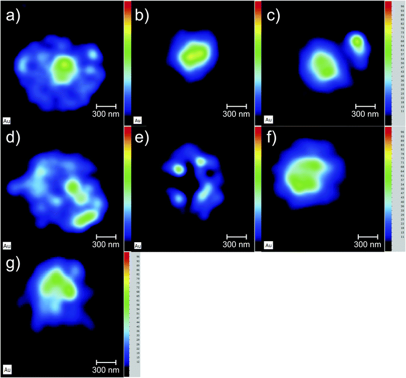
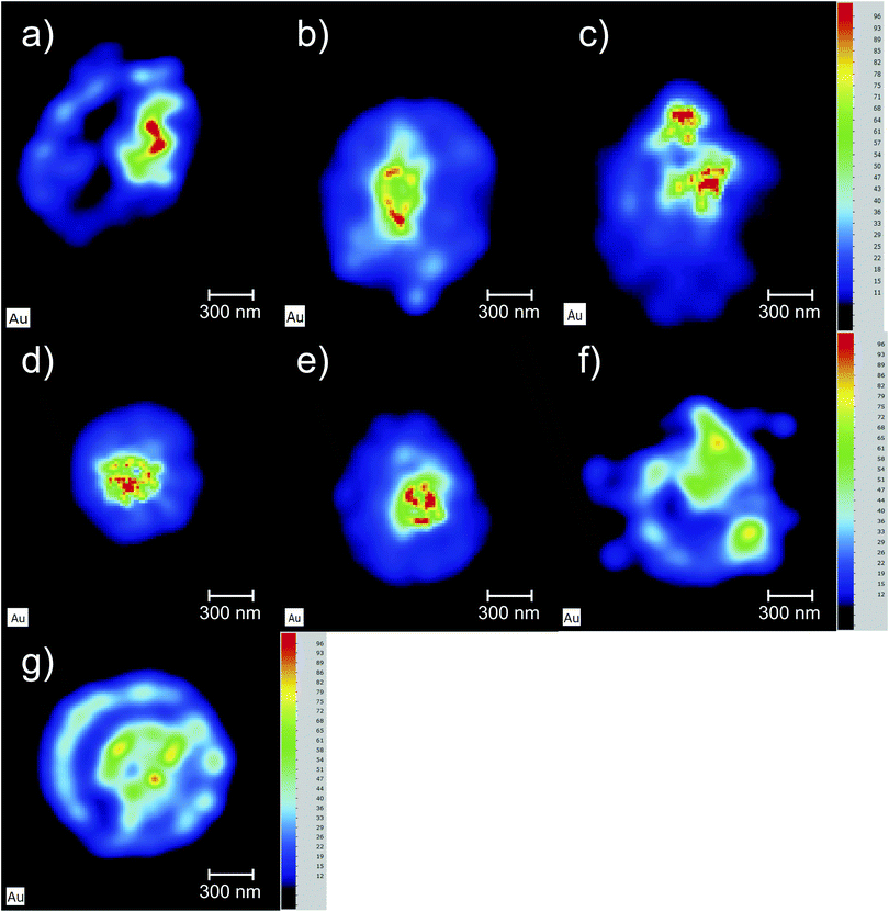
The Au elemental maps of the 14 (7 × 2) measured samples are shown in Fig. 4 for the NP that were fully covered with PEG, and in Fig. 5 for those whose coverage was only 30%.The quantification of the 3D cell culture maps were made by using the quantification curve of Fig. 1. The potassium signal was used to hand-select the area to quantify as it forms part of the matrix of the cell aggregates and is thus quite helpful in locating the spheroid within the hyperspectral map. In Table 2 the concentration values of both Au and K in each of the 14 samples is presented along with the sample label and the time that the cell aggregates spent in the PBS solution after being removed from the AuNP solution and before being placed in the sample holder for analysis. The placement of the samples in the sample holder took less than 30 seconds in order to maintain hydration of the cell culture throughout the X-ray measurements.
| Sample label | Time in PBS (h![[thin space (1/6-em)]](https://www.rsc.org/images/entities/char_2009.gif) : :![[thin space (1/6-em)]](https://www.rsc.org/images/entities/char_2009.gif) m) m) |
Au concentration (μg g−1) | K concentration (μg g−1) |
|---|---|---|---|
| AuNP@PEG100%_1 (a) | 0:00 | 11.1 ± 0.6 | 14![[thin space (1/6-em)]](https://www.rsc.org/images/entities/char_2009.gif) 500 ± 700 500 ± 700 |
| AuNP@PEG100%_2 (b) | 0:01 | 22.4 ± 1.0 | 15![[thin space (1/6-em)]](https://www.rsc.org/images/entities/char_2009.gif) 200 ± 700 200 ± 700 |
| AuNP@PEG100%_7 (c) | 0:25 | 25.4 ± 1.1 | 14![[thin space (1/6-em)]](https://www.rsc.org/images/entities/char_2009.gif) 000 ± 600 000 ± 600 |
| AuNP@PEG100%_3 (d) | 1:06 | 10.9 ± 0.6 | 12![[thin space (1/6-em)]](https://www.rsc.org/images/entities/char_2009.gif) 800 ± 600 800 ± 600 |
| AuNP@PEG100%_4 (e) | 1:50 | 7.3 ± 0.4 | 10![[thin space (1/6-em)]](https://www.rsc.org/images/entities/char_2009.gif) 000 ± 500 000 ± 500 |
| AuNP@PEG100%_6 (f) | 2:17 | 22.2 ± 1.0 | 15![[thin space (1/6-em)]](https://www.rsc.org/images/entities/char_2009.gif) 500 ± 700 500 ± 700 |
| AuNP@PEG100%_5 (g) | 2:24 | 18.1 ± 0.9 | 16![[thin space (1/6-em)]](https://www.rsc.org/images/entities/char_2009.gif) 100 ± 700 100 ± 700 |
| Average | 16.8 | 14![[thin space (1/6-em)]](https://www.rsc.org/images/entities/char_2009.gif) 014 014 |
|
| Standard dev. | 6.48 | 1919.4 | |
| AuNP@PEG30%_1 (a) | 0:00 | 63 ± 3 | 13![[thin space (1/6-em)]](https://www.rsc.org/images/entities/char_2009.gif) 300 ± 600 300 ± 600 |
| AuNP@PEG30%_2 (b) | 0:01 | 97 ± 4 | 12![[thin space (1/6-em)]](https://www.rsc.org/images/entities/char_2009.gif) 700 ± 600 700 ± 600 |
| AuNP@PEG30%_7 (c) | 0:30 | 132 ± 6 | 14![[thin space (1/6-em)]](https://www.rsc.org/images/entities/char_2009.gif) 800 ± 700 800 ± 700 |
| AuNP@PEG30%_3 (d) | 0:58 | 160 ± 7 | 17![[thin space (1/6-em)]](https://www.rsc.org/images/entities/char_2009.gif) 000 ± 800 000 ± 800 |
| AuNP@PEG30%_6 (e) | 1:14 | 112 ± 5 | 14![[thin space (1/6-em)]](https://www.rsc.org/images/entities/char_2009.gif) 900 ± 700 900 ± 700 |
| AuNP@PEG30%_4 (f) | 1:27 | 50 ± 3 | 10![[thin space (1/6-em)]](https://www.rsc.org/images/entities/char_2009.gif) 300 ± 500 300 ± 500 |
| AuNP@PEG30%_5 (g) | 2:07 | 79 ± 4 | 11![[thin space (1/6-em)]](https://www.rsc.org/images/entities/char_2009.gif) 500 ± 500 500 ± 500 |
| Average | 99 | 13![[thin space (1/6-em)]](https://www.rsc.org/images/entities/char_2009.gif) 500 500 |
|
| Standard dev. | 36 | 2098.3 |
4.3 Diffusion of AuNP
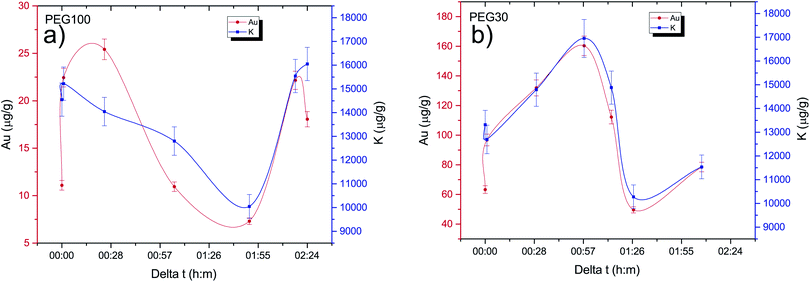
One of the goals of this work is to evaluate the diffusion mechanisms of the AuNPs within the cell aggregates. The cellular uptake mechanisms of nanoparticles have been recently studied by Behzadi et al.31 with special emphasis on their journey inside the cells. Diffusion mechanisms, which are driven by passive thermal motion as well as cellular uptake, that in turn depend not only on the physical characteristics of the NPs but also as their chemical funcionalization, are a very active field of study. As is well known, internalization of NPs depend on their size and shape and even on the configuration of the cells sample holder, as stated by Cho et al.32 Given the experimental design of this work and the idiosyncrasies of the experimental technique, we are not a priori able to distinguish active from passive (thermal) diffusion.As explained before, the 3D cell aggregates were left for 24 hours in a 10 nM solution of AuNP and then transferred to a PBS solution for different time intervals in order to see whether some thermal diffusion would occur from the AuNP enriched cell aggregates to the PBS solution. From Fick's first law one should be able to obtain the diffusion coefficient of the AuNP and the tortuosity parameter that could then be related to the cell cultures porosity.33 This would allow us to understand whether the passive diffusion mechanisms, that consist of the AuNP moving along the cell boundaries towards the interstices that are created during the culture's growth, are more or less pronounced than the cell internalization of the AuNP through endocytosis.31 In Fig. 6 the average concentration of Au and K for each spheroid is presented as a function of the time spent in the PBS solution after extraction from the AuNP solution. Each spheroid spent a different amount of time in the PBS solution, from those that were analyzed immediately after extraction or those that were only washed in PBS and then underwent analysis, to those that spent around 30 min to 2 h 30 m in the solution. If the diffusion of the AuNPs would occur in this time span we would be able to see a decrease in Au concentration as the time spent in PBS increases. However, as can be seen in Fig. 6, the concentration of Au seems to follow the concentration of K which should be relatively constant if all the spheroids had a similar density. The growth of the cell cultures is not homogeneous, resulting in aggregates with different shapes as can be seen in Fig. 4 and 5. In fact, from Fig. 4 one can see that samples (d) and (e) present a very odd shape with the later having a big hole in the center, which is consistent with them presenting a lower concentration of K. The same can be said for samples (a), (f) and (g) from Fig. 5.
4.4 Quantification calibration
One of the most important aspects when trying to characterize the penetration of AuNP within a 3D cell culture is to be able to correctly quantify the concentration of the NP in the spheroid. We were able to do this by developing a series of samples whose main composition is similar to the cancer cells from the point of view of X-ray attenuation. These samples allowed us to construct a calibration curve and thus be able to obtain the concentration of gold within any region of the cell aggregates. The Lower Detection Limit that was obtained from the calibration curve is compatible with the standard way of calculating this parameter (eqn (2)), and is low enough to investigate the diffusion of the AuNP at the nominal concentration of the solution that was employed in this work. From Fig. 1 we can observe the linearity of the X-ray counts as a function of the nominal concentration revealing that there are no saturation effects and that we are able to make AuNP solutions with a given concentration very accurately. From Fig. 2 we can see that up to 150 μg g−1 the Zn and Cu signal from the agarose matrix is very consistent, as expected, and for the highest concentration sample it seems to deviate slightly, albeit within the error bars. Although it is not completely clear why that occurs, one probable explanation has to do with a secondary excitation of the Zn atoms by the fluorescence radiation from the Au atoms, as the Zn K-shell ionization edge is just a few eV below the X-ray line energy of gold which makes the cross section for ionization of Zn atoms very high.4.5 Penetration of AuNPs in 3D cancer spheroids
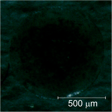
The data gathered from the diffusion experiment shows that the intrinsic variation between each spheroid regarding the accumulation of Au in their matrices is larger than the diffusion processes at play at least in the time span of the experiment. The fact that the Au signal follows the K concentration as a function of the time spent in the PBS solution, which in turn is correlated to variations in the density of the spheroids, does not allow us to make any kind of considerations regarding the diffusion coefficients either passive or active. We can, however, conclude that for both the AuNP@PEG100% and AuNP@PEG30% samples there seems to be an accumulation of the AuNP in the center of the cell aggregate. In fact, for the AuNP@PEG30% some ring structures around the center of the spheroid can be seen except in the samples that are oddly shaped and/or present holes in their inner regions. This ring structures can be seen in Fig. 7 which features a microscope image of one of the AuNP@PEG30% treated spheroids.Another interesting finding, is that the accumulation of the AuNP@PEG30% leads to much higher concentrations of Au in the spheroids when compared to their AuNP@PEG100% counterparts (Table 2 and Fig. 4 and 5). Both phenomena can be explained if we take into account the aggregation of the AuNP into larger size clusters. As it is well known, the coating of the nanoparticles leads to their stabilization as it hinders the formation of clusters,34 which has a direct influence on the internalization of the AuNPs into the cell aggregates as shown by Cho et al.,32 due to the sedimentation of the nanoparticles leading to an accumulation near the bottom of the cell culture holder and thus an increased internalization. This effect could explain the difference of almost one order of magnitude between the average concentration of Au in the AuNP@PEG100% and AuNP@PEG30% samples, but it doesn't fully explain the ring formations that can be seen in the AuNP@PEG30% spheroids. These ring structures should arise from a change in diffusion coefficients throughout the NP transport within the porous 3D spheroids, similar to what is seen in mobility studies of NP in porous media, specially in environmental studies. Very recently, Babakhani35 was able to describe the NP collection profiles in extraction wells by including NP aggregation in his theoretical model which led to a diffusion profile that was no longer an exponential but rather a non-monotonic distribution with a maximum at some distance from the injection well. This is very similar to what we observe in our experiment, as the AuNPs travel throughout the porous 3D cell culture, they start to aggregate up to a point where their mobility is reduced due to their size, being effectively trapped inside the spheroid. If the cluster formation is slower, as is the case of the AuNP@PEG100%, this immobility occurs deeper into the porous media. Another effect that might be at play is the fact that the aggregation of AuNPs increases for acid environments such as those that are found in the center of the 3D spheroids. The decreasing pH as we move towards the centre of the spheroid structure is associated to the difference in metabolic state of the cells, which at the core are experiencing a considerable level of hypoxia and, thus, increasing acidic species contributing to lower pH.28 Foroozandeh et al.36 concluded in their study that the internalization through endocytosis is enhanced for AuNP@PEG100% when compared to those that are not coated or only partially covered. This means that if we were seeing only the internalized NP in our maps, the AuNP@PEG100% samples would feature higher Au concentration. This is not the case because, most of the Au that we are seeing is from clusters of NPs that are outside the cell membrane and in the interstices of between cells. From both Fig. 4 and 5 we can conclude that for the AuNP@PEG100%, the diffusion time to reach the center of the cell spheroid is lower than the time that the AuNPs take to aggregate up to a size that strongly hinders their mobility, while for the AuNP@PEG30% NPs the aggregation is faster than the time it takes them to reach the center of the spheroid.
5 Conclusions
In this work, we evaluated the diffusion mechanism of AuNPs into tumour cell spheroids by X-ray fluorescence imaging. We started by creating a standard curve between EDXRF detector counts and the concentration of AuNPs in an aqueous matrix. We found that for concentrations up to 10 nM of AuNP the correlation is linear. This allowed us to quantify the concentration of AuNP that was retained inside tumour spheroids after 24H AuNP incubation. We showed that AuNP tend to accumulate in the core of spheroids for AuNP@PEG30% and AuNP@PEG100%.Interestingly AuNP@PEG30% seem to aggregate before arriving at the core of the spheroid, creating a highly concentrated circular AuNP precipitate. The same effect is not observed using AuNP@PEG100%, which are more stable, and tend to accumulate deeper in the spheroid core. We believe this differential aggregation pattern happens due to the acidic conditions in the core of the spheroids, and lower stability of AuNP@PEG30% over AuNP@PEG100%. We estimate that the AuNPs enter the spheroid through the interstitial spaces of adjacent cells and when arriving at the acid core, aggregate and get trapped. This study shows the potential of using EDXRF as a tool to track nanomaterial internalization in 3D spheroids.
Conflicts of interest
There are no conflicts to declare.Acknowledgements
This research was funded by Fundação para a Ciência e Tecnologia grant number UID/FIS/04559/2020 to LIBPhys-UNL and UIDB/04378/2020 to UCIBIO. The authors acknowledge the TEM service provided by Instituto Superior Técnico (ICEMS/IST), Portugal.Notes and references
- R. K. Jain and T. Stylianopoulos, Nat. Rev. Clin. Oncol., 2010, 7, 653–664 CrossRef CAS PubMed.
- P. Pedrosa, R. Vinhas, A. Fernandes and P. V. Baptista, Nanomaterials, 2015, 5, 1853–1879 CrossRef CAS PubMed.
- S. Barua and S. Mitragotri, Nano Today, 2014, 9, 223–243 CrossRef CAS PubMed.
- C. Jorgen and G. Lars, Curr. Cancer Ther. Rev., 2006, 2, 293–304 CrossRef.
- C. Walker, E. Mojares and A. D. R. Hernández, Int. J. Mol. Sci., 2018, 19, 3028 CrossRef PubMed.
- A. Tchoryk, V. Taresco, R. H. Argent, M. Ashford, P. R. Gellert, S. Stolnik, A. Grabowska and M. C. Garnett, Bioconjugate Chem., 2019, 30, 1371–1384 CrossRef CAS PubMed.
- H. Lu, J. Su, R. Mamdooh, Y. Li and M. H. Stenzel, Macromol. Biosci., 2020, 20, 1900221 CrossRef CAS PubMed.
- K. Huang, H. Ma, J. Liu, S. Huo, A. Kumar, T. Wei, X. Zhang, S. Jin, Y. Gan, P. C. Wang, S. He, X. Zhang and X. J. Liang, ACS Nano, 2012, 6, 4483–4493 CrossRef CAS PubMed.
- T. D. Rane and A. M. Armani, PLoS One, 2016, 11(12), e0167548 CrossRef PubMed.
- A. M. Permlid, P. Roci, E. Fredlund, F. Fält, E. Önell, F. Johansson and S. Oredsson, Toxicol. in Vitro, 2019, 60, 51–60 CrossRef PubMed.
- R. Edmondson, J. J. Broglie, A. F. Adcock and L. Yang, Assay Drug Dev. Technol., 2014, 12, 207–218 CrossRef CAS PubMed.
- D. Lv, Z. Hu, L. Lu, H. Lu and X. Xu, Oncol. Lett., 2017, 14, 6999–7010 Search PubMed.
- F. Sambale, A. Lavrentieva, F. Stahl, C. Blume, M. Stiesch, C. Kasper, D. Bahnemann and T. Scheper, J. Biotechnol., 2015, 205, 120–129 CrossRef CAS PubMed.
- J. Hoarau-Véchot, A. Rafii, C. Touboul and J. Pasquier, Int. J. Mol. Sci., 2018, 19, 181 CrossRef PubMed.
- M. J. Pushie, I. J. Pickering, M. Korbas, M. J. Hackett and G. N. George, Chem. Rev., 2014, 114, 8499–8541 CrossRef CAS PubMed.
- E. Lombi, E. Smith, T. H. Hansen, D. Paterson, M. D. de Jonge, D. L. Howard, D. P. Persson, S. Husted, C. Ryan and J. K. Schjoerring, J. Exp. Bot., 2011, 62, 273–282 CrossRef CAS PubMed.
- P. Cardoso, T. C. Mateus, G. Velu, R. P. Singh, J. P. Santos, M. L. Carvalho, V. M. Lourenço, F. Lidon, F. Reboredo and M. Guerra, Spectrochim. Acta, Part B, 2018, 141, 70–79 CrossRef CAS.
- R. Zhang, L. Li, Y. Sultanbawa and Z. P. Xu, Am. J. Nucl. Med. Mol. Imaging, 2018, 8, 169–188 CAS.
- H.-J. Wang, M. Wang, B. Wang, X.-Y. Meng, Y. Wang, M. Li, W.-Y. Feng, Y.-L. Zhao and Z.-F. Chai, J. Anal. At. Spectrom., 2010, 25, 328–333 RSC.
- G. Falkenberg, G. Fleissner, G. Fleissner, P. Alraun, U. Boesenberg and K. Spiers, X-Ray Spectrom., 2017, 46, 467–473 CrossRef CAS.
- B. Pemmer, A. Roschger, A. Wastl, J. G. Hofstaetter, P. Wobrauschek, R. Simon, H. W. Thaler, P. Roschger, K. Klaushofer and C. Streli, Bone, 2013, 57, 184–193 CrossRef CAS PubMed.
- M. Guerra, C. Ferreira, M. L. Carvalho, J. P. Santos and S. Pessanha, Spectrochim. Acta, Part B, 2016, 122, 114–117 CrossRef CAS.
- M. R. Gherase and D. E. B. Fleming, Crystals, 2020, 2020, 12 Search PubMed.
- L. Veith, D. Dietrich, A. Vennemann, D. Breitenstein, C. Engelhard, U. Karst, M. Sperling, M. Wiemann and B. Hagenhoff, J. Anal. At. Spectrom., 2018, 33, 491–501 RSC.
- M. Santibáñez, R. Saavedra, J. Vedelago, F. Malano and M. Valente, Radiat. Phys. Chem., 2019, 165, 108415 CrossRef.
- P. C. Lee and D. Meisel, J. Phys. Chem., 1982, 86, 3391–3395 CrossRef CAS.
- N. Baek, O. W. Seo, M. Kim, J. Hulme and S. S. A. An, OncoTargets Ther., 2016, 9, 7207–7218 CrossRef CAS PubMed.
- C. Roma-Rodrigues, I. Pombo, A. R. Fernandes and P. V. Baptista, Int. J. Mol. Sci., 2020, 21, 8017 CrossRef CAS PubMed.
- R. D. Deslattes, E. G. Kessler, P. Indelicato, L. de Billy, E. Lindroth and J. Anton, Rev. Mod. Phys., 2003, 75, 35–99 CrossRef CAS.
- I. Ramos, I. M. Pataco, M. P. Mourinho, F. Lidon, F. Reboredo, M. F. Pessoa, M. L. Carvalho, J. P. Santos and M. Guerra, Spectrochim. Acta, Part B, 2016, 120, 30–36 CrossRef CAS.
- S. Behzadi, V. Serpooshan, W. Tao, M. A. Hamaly, M. Y. Alkawareek, E. C. Dreaden, D. Brown, A. M. Alkilany, O. C. Farokhzad and M. Mahmoudi, Chem. Soc. Rev., 2017, 46, 4218–4244 RSC.
- E. C. Cho, Q. Zhang and Y. Xia, Nat. Nanotechnol., 2011, 6, 385 CrossRef CAS PubMed.
- L. Ma, C. Zhou, B. Lin and W. Li, Biomed. Microdevices, 2010, 12, 753–760 CrossRef PubMed.
- M. Neamtu, C. Nadejde, V.-D. Hodoroaba, R. J. Schneider, L. Verestiuc and U. Panne, Sci. Rep., 2018, 8, 6278 CrossRef PubMed.
- P. Babakhani, Sci. Rep., 2019, 9, 14071 CrossRef PubMed.
- P. Foroozandeh and A. A. Aziz, Nanoscale Res. Lett., 2018, 13, 339 CrossRef PubMed.
| This journal is © The Royal Society of Chemistry 2021 |

