
 Open Access Article
 This Open Access Article is licensed under a Creative Commons Attribution-Non Commercial 3.0 Unported Licence
Flexible electrochromic devices based on tungsten oxide and Prussian blue nanoparticles for automobile applications†
Chan Yang Jeongab,
Takashi Kubotaa and
Kazuki Tajima *a
*a
aNational Institute of Advanced Industrial Science and Technology (AIST), 1-1-1 Higashi, Tsukuba, Ibaraki 305-8565, Japan. E-mail: k-tajima@aist.go.jp
bKitami Institute of Technology (KIT), 165 Koen-cho, Kitami, Hokkaido 090-8507, Japan
First published on 24th August 2021
Abstract
Smart windows, which control the amount of light entering buildings, houses, and automobiles, are promising in terms of energy conservation and their low environmental impact. Particularly, a next-generation smart window for automobiles will require high optical modulation, along with flexibility to adapt to various intelligent designs. We have previously fabricated electrochromic devices (ECDs) by wet coating glass substrates with nanoparticles (NPs), such as water-dispersive ink containing tungsten oxide (WO3), and Prussian blue (PB), and have evaluated and confirmed the various electrochromic (EC) properties, such as optical modulation, cyclic durability, and colouration efficiency, of the ECDs. However, glass substrates are heavy and difficult to adapt by deformation to meet the demand of next-generation automobiles. In this study, we aim to prepare complementary ECDs by wet coating WO3 and PB thin films on indium tin oxide (ITO)-coated flexible polyethylene terephthalate (PET) substrates. Chromaticity and haze of ECDs were investigated in detail as evaluation indexes to verify specifications for practical use in automotive applications. Repeated switching, bending, and twisting did not degrade the ECD properties, thereby demonstrating its durability and mechanical robustness. These excellent electrochromic properties of the flexible ECDs suggest that they are promising materials for application in next-generation smart windows for automobiles.
Introduction
A “smart” automobile window is one that has flexibility to autonomously change its optical properties to admit or block solar energy in response to seasonal changes.1–3 Recently, suspended particle devices (SPDs) have been developed for commercial automobile window applications.4,5 However, due to the disadvantages of SPDs, such as poor thermal and electrical stabilities and poor memory effect, they cannot meet the demands of future automobile development. In contrast, electrochromic (EC) materials have high thermal and electrochemical stabilities as well as good memory properties, and are thus considered suitable candidates for automobile window applications. Upon application of a certain voltage, EC materials can switch their optical properties persistently and reversibly by balancing charges via simultaneous intercalation/deintercalation of cations (e.g., H+, Li+, etc.) and electrons.6–8 EC materials have been extensively investigated due to their potential for widespread application in information displays, automotive rear-view mirrors, and smart windows.9–11A typical EC device comprises five superimposed layers: a transparent conductive electrode, an ion storage layer, an electrolyte layer, a EC layer, and a transparent conductive electrode.12,13 The ion storage layer prevents ion accumulation on the electrode to maintain the neutrality of the electrolyte layer. The electrolyte layer is ion-conductive and provides a transport channel for the shuttling of ions between the EC and ion storage layers.
EC materials are mainly categorized as inorganic and organic materials. Inorganic materials include transition metal oxides (e.g., tungsten oxide (WO3)14) and inorganic complexes (e.g., Prussian blue (PB)15–17), while organic materials include π-conjugated organic molecules (e.g., viologen18) and conductive polymers (e.g., polyimide19). In particular, WO3 and PB are representative EC materials that exhibit large optical modulation and high colouration efficiency in the visible and near-infrared regions. Interestingly, Wang et al.20 reported not only a bi-functional device, but also a self-rechargeable transparent battery, using PB having EC characteristics.
EC layers for application in commercial smart windows can be prepared by thermal evaporation,21 electrodeposition,22 and sputtering.23 In recent years, hydrothermal methods,24–26 sol–gel methods,27 along with electrodeposition,28 printing,29 and coating30 techniques, have been investigated to reduce process cost for high productivity. These coating and printing techniques can be used to rapidly fabricate high-quality EC thin films on large substrates. Thus, these techniques show promise for the development of next-generation flexible ECDs.30,31 However, this development relies on extensive basic research, because several issues must be resolved to enable mass production, ensure process safety (e.g., minimise the use of substances that can harm the environment), and allow for easier handling.
We have previously developed a complementary coated ECD using WO3 and PB nanoparticles (NPs).14,32 The WO3 and PB thin films were coated with an ink containing each of these NPs dispersed in water, thus ensuring processing safety. Slit coating was also evaluated for the fabrication of large-area thin films on a G2 (370 mm × 470 mm)-sized indium tin oxide (ITO)-coated glass substrate.33 High-quality EC thin films can be fabricated in a short period at a low cost using wet coating techniques, such as slit-coating34 and roll-to-roll35 methods. However, suitability of the application of these WO3 and PB inks on flexible substrates has not yet been evaluated.
In this study, we aimed to fabricate a flexible ECD by coating WO3 and PB on ITO-coated polyethylene terephthalate (PET) as a substrate material. The ECD performance was evaluated in terms of EC properties, including optical density change, colouration efficiency, and response time, of the assembled device. Particularly, it is preferable to use glazing in automobile windows because it affords high transmittance in a transparent state with no excessive light scattering;36,37 therefore, we investigated the haze and chromaticity of the coloured and transparent states of the ECD fabricated on a PET substrate in detail. ECDs fabricated on conventional glass and flexible substrates were also compared. The primary aim of the research described herein and future research is the development of a coated film for application in automobile smart windows.
Experimental
Water-dispersed WO3 and PB NP inks
Water-dispersed PB and WO3 NP inks were prepared by following methods reported in our previous papers.14–16,32 Water-dispersed PB NP ink was prepared by mixing Fe(NO3)3·9H2O with Na4[Fe(CN)6]·10H2O, followed by washing via decantation. The dispersibility of the precipitate in water was improved by adding Na4[Fe(CN)6]·10H2O, and the suspension was stirred at room temperature for 1 week. Polyvinyl alcohol (PVA; 10 wt%) was added for increased viscosity and adhesion of the ink to ensure that a uniform PB film was formed.WO3 NPs (diameter ≈ 10 nm; Toshiba Materials Co.) were dispersed in purified water to a solid content of 25 wt%, followed by stirring at 1000 rpm for 48 h at 20 °C. PVA (1 wt%) was added for increased viscosity and adhesion of the ink to ensure that a uniform WO3 film was formed. The water-dispersed WO3 and PB NP inks were both filtered through a 7 μm syringe filter (Kiriyama Glass Co.) before use. The properties of the inks are listed in Table S1.†
Surface treatment of substrates
ITO-coated glass and PET were both used as substrate materials (area = 25 cm2). Both substrates received surface treatments to improve ink coating efficiency and thin film adhesion. After setting the moving distance of the conveyor to 50 mm, the surfaces were repeatedly irradiated with ultraviolet (UV) light (λ = 365 nm) for 25 min at a conveyor speed of 10 mm min−1, with the distance between the substrate and UV light emitting ceramic lamp being 10 mm (HLDL-375X10U6-SP, CCS Inc.; Fig. 1). The UV dose was adjusted between 0 and 2805 mW s cm−2. The temperature was controlled using a cooling fan (<80 °C), and temperature labels were used to avoid heating of the flexible substrate surface during UV treatment. The contact angles for water and the PB and WO3 NP inks dropped onto the ITO-coated glass and flexible substrate surfaces were measured after 60 s using a contact angle meter (DMs-400, Kyowa Interface Science Co., Ltd).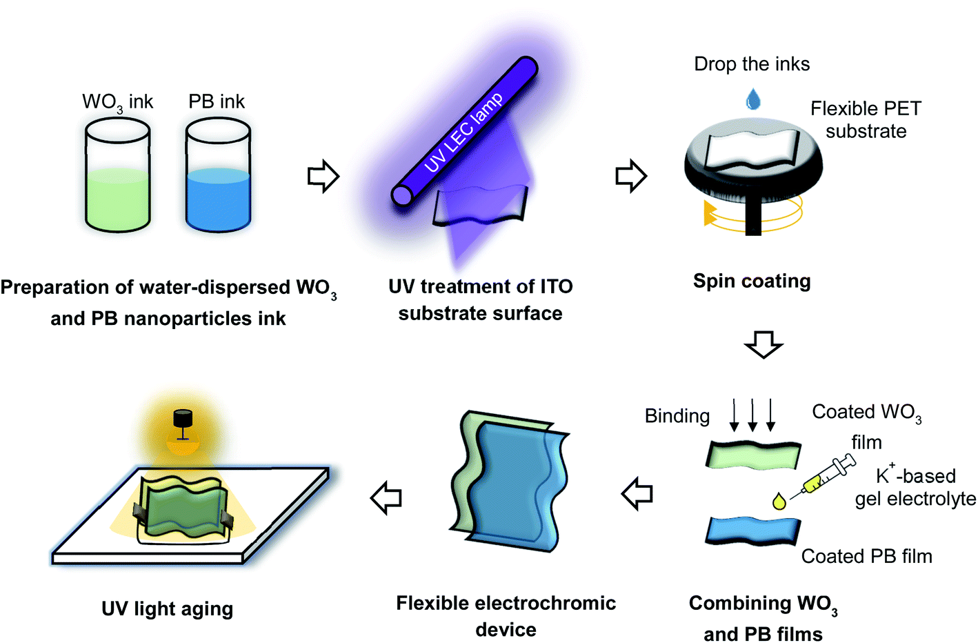 | ||
| Fig. 1 Schematic of ECD preparation. | ||
Electrochromic thin films prepared using water-dispersible NP inks
WO3 and PB thin films were deposited on surface-treated ITO-coated glass and flexible PET substrates by spin-coating (POLOS Spin150i, SPS Europe, Inc.). The spin parameters are listed in Table S2.† The speed (rpm) of the spin-coating process was controlled to yield a film thickness of ∼1 μm. The film thickness (d) was determined as follows:38| d = m/(A × ρ), | (1) |
Fabrication of electrochromic devices (ECDs)
The gel electrolyte was prepared by mixing potassium bis(trifluoromethanesulfonyl)imide (KTFSI, 1.5 mol kg−1; FUJIFILM Wako Pure Chemicals Co.) and polycarbonate (PC, 99%; Kanto Chemicals Co., Inc.). The electrolyte viscosity was adjusted by adding 30 wt% polymethyl methacrylate (PMMA; FUJIFILM Wako Pure Chemicals Co.). The electrolyte was applied to the PB thin film, and a UV sealing material was applied to the four edges of the PB thin film to prevent electrolyte leakage. Next, WO3 thin film was bonded to the PB thin film with the electrolyte and UV seal material applied under vacuum. The effective area of the devices was 16 cm2. The ECDs produced in this study are referred to as either a glass-based ECD or a PET-based ECD.A light-ageing treatment was performed to improve the performance of the ECDs, by irradiating the ECDs with a xenon lamp (Q-SUN XE-1 Xenon Test Chamber, Q-Lab Co.) operated at a power density of 80 mW cm−2 for 60 min, placed 50 mm from the ECDs (Fig. 1). The electrodes at both ends of the prepared ECDs were short-circuited before light-ageing. Upon light-ageing, the appearance of the ECDs was switched from blue to transparent.
ECD characterisation
The ECDs were evaluated in accordance with protocols used in our previous studies.14,32 The chromaticity was measured using a UV-visible (UV-vis) spectrophotometer (SD 3000, Nippon Denshoku Industries Co. Ltd), while the haze was determined using a haze meter (NDH 7000, Nippon Denshoku Industries Co. Ltd). The chromaticity coordinates (a* and b*) and luminance (L*) data were calculated from the transmittance spectra of PET-based and glass-based ECDs in their coloured and bleached states. The luminance (L*) value characterizes the brightness of the films and varies between 0 (black) and 100 (white). The colour of the films is defined by their a* and b* coordinates: positive and negative a* values indicate that the colour tends toward red and green, respectively, while positive and negative b* values indicate that the colour tends toward yellow and blue, respectively. The electrochemical properties were evaluated using an electrochemical analyser (6115D, ALS/HCH), in combination with a UV-visible-near-infrared (UV-vis-NIR) light source (DH-2000, Ocean Optics Inc.). Cyclic voltammetry (CV) was performed to estimate the peak potentials and peak currents of the reversible redox reactions at the anode and cathode. Multiple potential step (MPS) measurements, transmission spectra, and time strip charts were obtained based on estimated response times. Chronocoulometry (CC) was conducted to estimate the transferred charge density (Q), with respect to the transformation of ECDs from the transparent to the coloured states.Results and discussion
Surface treatment of ITO substrates
The hydrophilization of a substrate surface is commonly achieved using the vacuum plasma method.39 However, this approach can lead to plasma damage in organic substrates. Therefore, in this study, the surfaces were treated with UV light. UV-based hydrophilic treatments help remove contaminants from the ITO surface by breaking the organic molecular bonds and adding polar oxygen atoms. These modifications increase the surface energy of ITO.40–42 The contact angles for water and the PB and WO3 inks dropped on the surface-treated substrates were evaluated after treatment at various UV irradiation intensities (Fig. 2). The contact angles of water, WO3, and PB were found to decrease from ∼90° to 32°, 48°, and 47°, respectively, with increasing UV dose; the optimal effect without any damage to the flexible substrate was achieved at a UV dose of 2805 mW s cm−2. The UV surface treatment reduced the content of non-polar groups, while increasing the content of polar components, and the formation of various photo oxides on the ITO surface led to increased hydrophilicity.40–42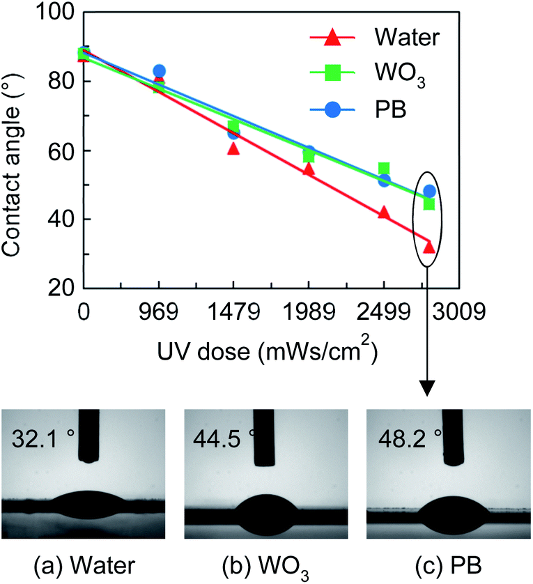 | ||
| Fig. 2 Contact angles for water and the PB and WO3 inks dropped on the ITO/PET substrate after UV treatment at various UV irradiation intensities. The photos show the contact angle of (a) water, (b) WO3, and (c) PB on the surface of ITO-coated PET substrate treated with a UV dose of 2805 mW s cm−2. | ||
Effect of light-ageing on ECD properties
Light-ageing of the ECDs with short-circuited electrodes afforded a transparent appearance due to presence of oxidised WO3 and reduced PB. UV irradiation facilitated the injection of K+ into the electronic states of PB for the reduction of FeIII–N to FeII–N as follows:43,44| FeIII4[FeII(CN)6] (blue) + 4K− + 4e− ⇒ K4FeII4[FeII(CN)6] (colorless) | (2) |
The PB thin film in the sealed ECD was protected from oxidative degradation, thereby minimising its participation in the oxidation of PB.44,45
Electrochemical and EC properties
The CV curve recorded at an applied potential ranging from −1.2 to +1.0 V at a sweep rate of 5 mV s−1 is shown in Fig. 3(a). The PET-based ECD exhibited a significantly smaller CV area than the glass-based ECDs, probably because the sheet resistance of the ITO/PET substrate (∼50 Ω sq−1) was about four times higher than that of the ITO/glass substrate (∼12 Ω sq−1). The charges of the glass and PET-based ECDs were 0.44 and 0.23 C, respectively, when a potential of −1.2 and +1.0 V was applied for 60 s (Fig. 3(b)). Thus, the glass-based ECD with a low electrical resistance had double the charge for oxidation and reduction reactions compared to the PET-based ECD. However, the PET-based ECD had an estimated charge balance (Ctransparent/Ccoloured) of over 98%, indicating that reversible K+ charge/discharge processes occurred smoothly in both ECDs, as described in eqn (3) and (4):46,47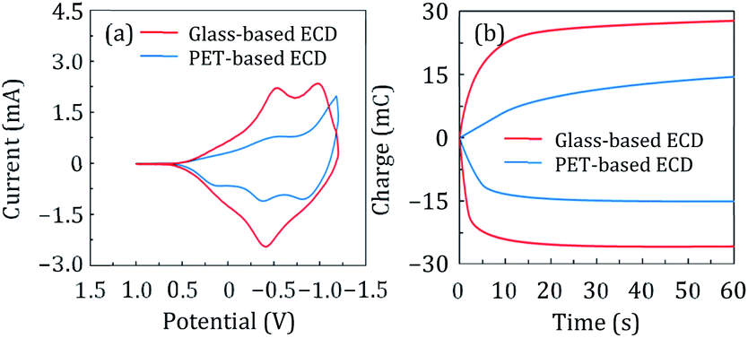 | ||
| Fig. 3 (a) CV and (b) CC profiles of the glass-based (red) and PET-based (blue) ECDs acquired at a potential scan rate of 5 mV s−1. | ||
Anodic reaction:
| K4FeII4[FeII(CN)6] (colorless) ⇔ FeIII4[FeII(CN)6] (blue) + 4K− + 4e− | (3) |
Cathodic reaction:
| WO3 (colorless) + xK+ + e− = KxWO3 (blue) | (4) |
The changes in optical transmittance of the coloured and transparent ECDs were examined using UV-vis spectroscopy during CC analysis, and the corresponding spectra are shown in Fig. 4(a) and (b). The glass and PET-based ECDs exhibited optical modulations of 80% and 79%, respectively, at a wavelength of 633 nm. Both the ECDs exhibited excellent optical properties. MPS measurement were conducted to determine the switching responses of the films. The changes in optical transmittance with time at a wavelength of 700 nm upon applying constant voltages of +1.0, −1.2 and +1.0 V, as Vinitial, Vstep1, and Vstep2, for 30, 30, and 60 s, respectively, are shown in Fig. 4(c) and (d). The switching times of the ECDs between the coloured (tcoloured) and transparent (ttransparent) states was evaluated using the time in which 90% change in transmittance was achieved. The PET-based ECD exhibited tcoloured and ttransparent values of 16.79 and 19.03 s, respectively, which were higher than those of the glass-based ECD. However, there was no significant difference in the response time between the two types of ECDs, as obtained in the CV and CC analyses (Fig. 3), despite the lower current values. This result shows promise for lower current drive in future applications, which could reduce the power consumption of a device. A shorter switching time is also expected if a substrate with a lower sheet resistance than ITO-coated substrates is used.
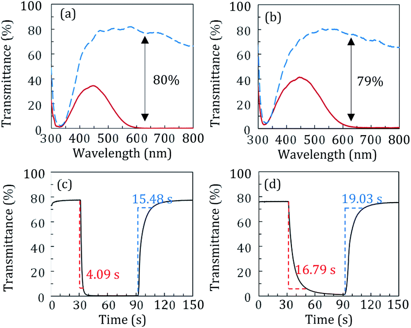 | ||
| Fig. 4 Transmittance spectra of the transparent (blue lines) and coloured (red lines) states of (a) PET-based and (b) glass-based ECDs. Optical switching speed between the transparent (blue lines) and coloured (red lines) states of (c) PET-based and (d) glass-based ECDs. | ||
Fig. 5 shows the chromaticity and haze of the ECDs, aspects that are important for meeting the regulations governing window materials for automobiles (the details of the haze and chromaticity values are described in Table S4†). In the CIELAB colour space designed to approximate the human vision, the colour coordinate values (L*, a*, and b*) of the ITO-coated PET- and glass-based ECDs were determined in transparent and coloured states (Fig. 5(a) and (b)). When −1.2 V was applied, the a* and b* values of both types of ECDs suddenly dropped below −15, corresponding to blue colour. Conversely, upon the application of +1.0 V, both types of ECDs changed from blue colour to transparent (L* > 85). In addition, the haze values are low (<5%) in the transparent states of PET-based and glass-based ECDs. For application in windows, visual transmittance must be high, desirably >70%, and haze must be low, desirably <2%.48 The PET-based ECD appears remarkably clean with haze <3% in the transparent state, which is adequate for use as ECDs. Moreover, the ECDs maintained their coloured and transparent states even when disconnected from the power source, demonstrating it as a promising energy-efficient device.
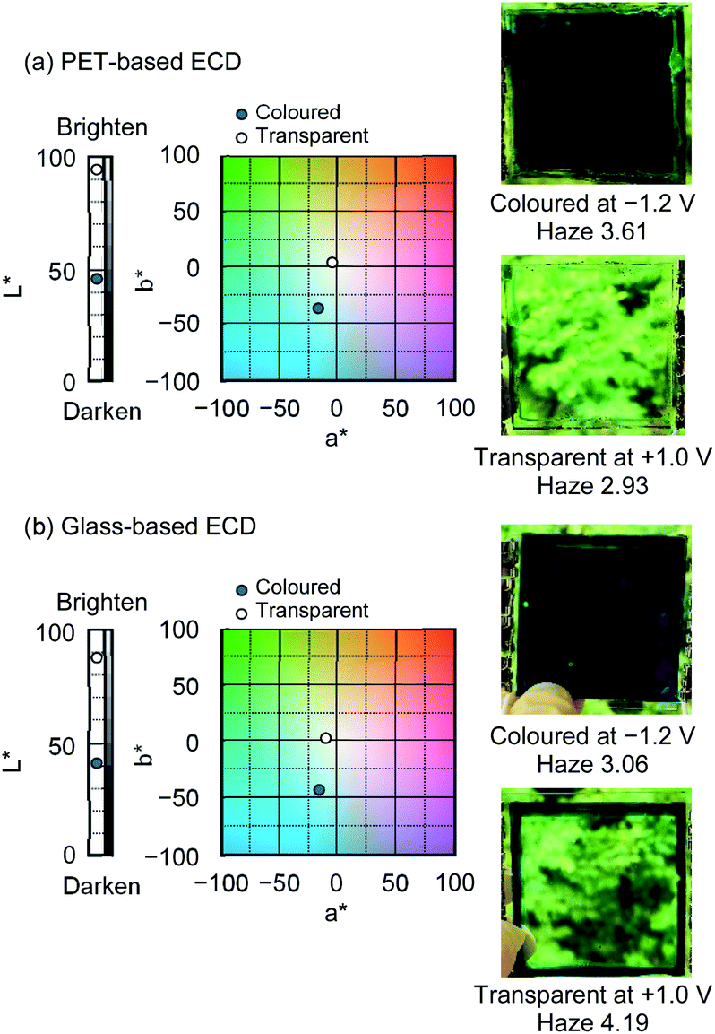 | ||
| Fig. 5 Variation in CIELAB colour coordinates (L*, a*, b*) and photographs of the (a) PET-based and (b) glass-based ECDs in the colored and transparent states. | ||
The current and transmittance at 633 nm were evaluated as a function of the number of continuous colouration/discolouration cycles up to 100 (Fig. 6). Both ECDs exhibited no change in the initial and subsequent electrochemical properties, and no notable degradation was observed in EC performance. Thus, the ECDs were electrochemically very stable. In addition, the PET-based ECD was mechanically robust during both bending and twisting (Movie S1†).
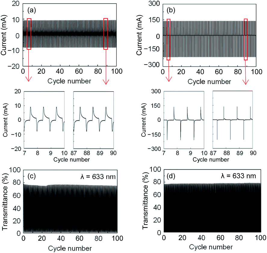 | ||
| Fig. 6 Cycle stability up to 100 cycles of (a and c) PET-based and (b and d) glass-based ECDs illustrated as (a and b) MPS measurements of electrochemical stability at constant voltages of −1.2 and +1.0 V, and (c and d) transmittance at a wavelength of 633 nm. | ||
Optical density (ΔOD) was used to calculate the EC colouration efficiency (CE), which is an important parameter governing the electrochemical performance of ECDs. CE and ΔOD are defined as follows:49
| CE = ΔOD/Q = log(Tt/Tc)/Q, | (5) |
Conclusions
A novel flexible ECD was prepared by coating water-based inks containing WO3 and PB NPs onto ITO-coated PET substrates. UV-treatment of ITO-coated substrates enhanced the wettability of the surface, which facilitated the adhesion of the WO3 and PB inks to the films. A complementary flexible ECD was produced using K+-based gel electrolyte. Light-ageing was conducted to improve the EC performance of the PET-based ECD. To illustrate the colour change, the chromaticity diagram is plotted in terms of L*, a*, and b*, and the PET-based ECD showed a dramatic colour change from blue to transparent. Furthermore, the haze of the PET-based ECD in the transparent state was less than 3%, indicating clear transparency; therefore, transparent PET-based ECD is considered suitable for automobile applications. The ECDs exhibited excellent EC performance, including a large optical modulation of 79% at 633 nm, high CE (123.32 cm2 C−1), and good cycling stability. These excellent EC properties of the flexible WO3-based and PB-based ECDs demonstrate their promise as candidate materials for application in next-generation smart windows. However, when considering the application of this device as a window material for automobiles, several issues remain, including environmental stability (e.g., resistance to temperature, humidity, UV) and introduction methods. Future research and development in collaboration with our partner companies is required to produce scaled-up samples for field testing, thus facilitating rapid practical implementation.Conflicts of interest
There are no conflicts to declare.Acknowledgements
This research was supported in part by Toshiba Materials Co. Ltd, who also supplied the WO3 nanoparticles. This research was also partially supported by JST A-STEP Grant Number JPMJTR203D, Japan.References
- F. M. Andersen, H. K. Jacobsen and P. A. Gunkel, Int. J. Electr. Power Energy Syst., 2021, 130, 106900 CrossRef.
- S. Fd da Silva, J. J. Eckert, F. L. Silva, L. C. A. Silva and F. G. Dedini, Energy Convers. Manage., 2021, 234, 113909 CrossRef.
- G. Doluweera, F. Hahn, J. Bergerson and M. Pruckner, Appl. Energy, 2020, 268, 114961 CrossRef.
- F. Ren, S. Huang, F. Yang, A. Yurtsever and D. Ma, J. Mater. Chem. A, 2018, 6, 24157–24165 RSC.
- S. Huang, Q. Zhang, F. Yang, D. T. Gangadharan, P. Li, F. Ren, B. Sun and D. Ma, J. Mater. Chem. A, 2020, 8, 8620–8628 RSC.
- A. Llordes, G. Garcia, J. Gazquez and D. J. Milliron, Nature, 2013, 500, 323–326 CrossRef CAS PubMed.
- X. Xie, K. Kretschmer and G. Wang, Nanoscale, 2015, 7, 13278–13292 RSC.
- R.-T. Wen, C. G. Granqvist and G. A. Niklasson, Nat. Mater., 2015, 14, 996–1001 CrossRef CAS PubMed.
- M. Gratzel, Nature, 2001, 409, 575–576 CrossRef CAS PubMed.
- C. G. Granqvist, Sol. Energy Mater. Sol. Cells, 2000, 60, 201–262 CrossRef CAS.
- C. Y. Yan, W. B. Kang, J. X. Wang, M. Q. Cui, X. Wang, C. Y. Foo, K. J. Chee and P. S. Lee, ACS Nano, 2013, 8, 316–322 CrossRef PubMed.
- C. G. Granqvist, Thin Solid Films, 2014, 564, 1–38 CrossRef CAS.
- C. G. Granqvist, P. C. Lansåker, N. R. Mlyuka, G. A. Niklasson and E. Avendano, Sol. Energy Mater. Sol. Cells, 2009, 93, 2032–2039 CrossRef CAS.
- C. Y. Jeong, H. Watanabe and K. Tajima, Electrochim. Acta, 2021, 389, 138764 CrossRef CAS.
- M. Ishizaki, K. Kanaizuka, M. Abe, Y. Hoshi, M. Sakamoto, T. Kawamoto, H. Tanaka and M. Kurihara, Green Chem., 2012, 14, 1537–1544 RSC.
- M. Ishizaki, Y. Sajima, S. Tsuruta, A. Gotoh, M. Sakamoto, T. Kawamoto, H. Tanaka and M. Kurihara, Chem. Lett., 2009, 39, 1058–1059 CrossRef.
- A. Kraft, Ionics, 2021, 27, 2289–2305 CrossRef CAS.
- K. Madasamy, D. Velayutham, V. Suryanarayanan, M. Kathiresan and K.-C. Ho, J. Mater. Chem. C, 2019, 7, 4622–4637 RSC.
- H.-M. Wang and S.-H. Hsiao, J. Mater. Chem. C, 2014, 2, 1553–1564 RSC.
- J. Wang, L. Zhang, L. Yu, Z. Jiao, H. Xie, X. W. D. Lou and X. W. Sun, Nat. Commun., 2014, 5, 4921 CrossRef CAS.
- P. H. Yang, P. Sun, Z. S. Chai, L. H. Huang, X. Cai, S. Z. Tan, J. H. Song and W. J. Mai, Angew. Chem., Int. Ed., 2014, 53, 11935–11939 CrossRef CAS.
- Z. Z. He, B. B. Gao, T. Li, J. L. Liao, B. Liu, X. J. Liu, C. Y. Wang, Z. Q. Feng and Z. Z. Gu, ACS Sustainable Chem. Eng., 2019, 7, 1745–1752 CrossRef CAS.
- K. S. Usha, R. Sivakumar, C. Sanjeeviraja, V. Sathe, V. Ganesan and T. Y. Wang, RSC Adv., 2016, 6, 79668–79680 RSC.
- D. Ma, T. Li, Z. Xu, L. Wang and J. Wang, Sol. Energy Mater. Sol. Cells, 2018, 177, 51–56 CrossRef CAS.
- J. Qian, D. Ma, Z. Xu, D. Li and J. Wang, Sol. Energy Mater. Sol. Cells, 2018, 177, 9–14 CrossRef CAS.
- J. Wang, E. Khoo, P. S. Lee and J. Ma, J. Phys. Chem. C, 2008, 112, 14306–14312 CrossRef CAS.
- Y. Ren, T. Fang, Y. Gong, X. Zhou, G. Zhao, Y. Gao, J. Jia and Z. Duan, J. Mater. Chem. C, 2019, 7, 6964–6971 RSC.
- G. Cai, P. Darmawan, M. Cui, J. Chen, X. Wang, A. L.-S. Eh, S. Magdassi and P. S. Lee, Nanoscale, 2016, 8, 348–357 RSC.
- X. Li, K. Perera, J. He, A. Gumyusenge and J. Mei, J. Mater. Chem. C, 2019, 7, 12761–12789 RSC.
- S. Lin, X. Bai, H. Wang, H. Wang, J. Song, K. Huang, C. Wang, N. Wang, B. Li, M. Lei and H. Wu, Adv. Mater., 2017, 29, 1703238 CrossRef.
- S.-H. Park, S.-M. Lee, E.-H. Ko, T.-H. Kim, Y.-C. Nah, S.-J. Lee, J. H. Lee and H.-K. Kim, Sci. Rep., 2016, 6, 33868 CrossRef CAS PubMed.
- K. Tajima, H. Watanabe, M. Nishino and T. Kawamoto, RSC Adv., 2020, 10, 2562–2565 RSC.
- K. Tajima, C. Y. Jeong, T. Kubota, T. Ito, K. Araki, T. Kamei and M. Fukui, Sol. Energy Mater. Sol. Cells Search PubMed , submitted.
- H. W. Ro, J. M. Downing, S. Engmann, A. A. Herzing, D. M. DeLongchamp, L. J. Richter, S. Mukherjee, H. Ade, M. Abdelsamie, L. K. Jagadamma, A. Amassian, Y. Liue and H. Yan, Energy Environ. Sci., 2016, 9, 2835–2846 RSC.
- J. Kim, J. Ahn, J. Shin, K. J. Yoon, J.-W. Son, J.-H. Lee, D. Shin, H.-W. Lee and H.-I. Ji, J. Mater. Chem. A, 2019, 7, 9958–9967 RSC.
- C. G. Granqvist, S. Green, E. K. Jonson, R. Marsal, G. A. Niklasson, A. Roos, Z. Topalian, A. Azens, P. Georén, G. Gustavsson, R. Karmhag, J. Smulko and L. B. Kish, Thin Solid Films, 2008, 516, 5921–5926 CrossRef CAS.
- A. Jonsson, A. Roos and E. K. Jonson, Sol. Energy Mater. Sol. Cells, 2010, 94, 992–997 CrossRef CAS.
- H.-F. Xiang, Z.-X. Xu, V. A. L. Roy, C.-M. Che and P. T. Lai, Rev. Sci. Instrum., 2007, 78, 034104 CrossRef.
- Y. Takata, S. Hidaka, A. Yamashita and H. Yamamoto, Int. J. Heat Mass Transfer, 2004, 25, 320–328 CAS.
- Z. Xu, Z. Ao, D. Chu, A. Younis, C. M. Li and S. Li, Sci. Rep., 2014, 4, 6450 CrossRef CAS PubMed.
- E. Bormashenko, R. Pogreb, G. Whyman, Y. Bormashenko, R. Jager, T. Stein, A. Schechter and D. Aurbach, Langmuir, 2008, 24, 5977–5980 CrossRef CAS PubMed.
- H. Y. Nie, M. J. Walzak, B. Berno and N. S. McIntyre, Appl. Surf. Sci., 1999, 144, 627–632 CrossRef.
- C. Gervais, M. A. Languille, S. Reguer, M. Gillet, E. P. Vicenzi, S. Chagnot, F. Baudelet and L. Bertrand, Appl. Phys. A: Mater. Sci. Process., 2013, 111, 15–22 CrossRef CAS.
- C. Gervais, M. A. Languille, S. Reguer, C. Garnier and M. Gillet, Heritage Sci., 2014, 2, 26 CrossRef.
- C. Y. Jeong, T. Kubota, K. Tajima, M. Kitamura and H. Imai, Mater. Chem. Phys. Search PubMed , submitted.
- F. Ricci, F. Arduini, A. Amine, D. Moscone and G. Palleschi, J. Electroanal. Chem., 2004, 563, 229–237 CrossRef CAS.
- M. Hepel, L. I. Dela-Moss and H. Redmond, J. Solid State Electrochem., 2014, 18, 1251–1260 CrossRef CAS.
- R. Koua, Y. Zhonga, J. Kim, Q. Wang, M. Wang, R. Chen and Y. Qiao, Energy Build., 2019, 193, 69–77 CrossRef.
- C. G. Granqvist, Handbook of Inorganic Electrochromic Materials, Elsevier, Amsterdam, 1995 Search PubMed.
- G. Cai, X. Cheng, M. Layani, A. W. M. Tan, S. Li, A. L.-S. D. Gao, S. Magdassi and P. S. Lee, Nano Energy, 2018, 49, 147–154 CrossRef CAS.
- W. Li, J. Suna, J. Zhang, O. A. Ganiyata and Y. Cui, Surf. Interfaces, 2021, 2, 100002 CrossRef.
- T. Y. Yun, X. Li, J. Bae, S. H. Kim and H. C. Moon, Mater. Des., 2019, 162, 45–51 CrossRef CAS.
Footnote |
| † Electronic supplementary information (ESI) available. See DOI: 10.1039/d1ra05280b |
| This journal is © The Royal Society of Chemistry 2021 |