 Open Access Article
Amalgamation of diverse hydrodynamic effects with novel triple-sided membrane valves for developing a microfluidic device for filterless and continuous water purification
Amit Prabhakar *a,
Ankur Jaiswara,
Neha Mishraa,
Praveen Kumara,
Amar Dhwaja,
Prashant Nayaka and
Deepti Verma*b
aDepartment of Applied Sciences, Indian Institute of Information Technology, Allahabad, 211015, India. E-mail: amit@iiita.ac.in
bDepartment of Chemistry, University of Allahabad, Allahabad, 211002, India. E-mail: deeptivermachem@gmail.com
First published on 25th August 2021
Abstract
The requirement for clean water has been increasing for several reasons, for instance, the fast industrialization of developing countries, climate change, environmental pollution, growth of biofuel use and the resulting growth in irrigation. To meet the requirements for contamination-free water, a cost-effective water treatment can substantially improve the developing world’s health, largely for children, and there is predicted to be a huge market for this. Existing water treatment processes consist of various phases that are time-consuming as well as pricey. There is an essential demand for cost-effective point of use methods to purify drinking water to reduce the impact of diseases induced by numerous waterborne pathogens. The development of micro-devices, with different outcomes, can be a helpful solution to various problems. To make this reality, a novel microfluidic device for the purification of water, with multiple hydrodynamic effects, has been shown in this paper. In the proposed novel device, the network of interconnected microfluidic channels was created in such a way that an amalgamation of multiple effects, such as the Fåhræus effect, centrifugal force, the Zweifach–Fung effect and constriction followed by expansion, act together in the microchannel to separate suspended impurities (i.e. bacteria and similar length scale particles present in water in the suspension form) from water. Furthermore, to improve the bacterial separation efficiency of the device, the pure water channel of the microdevice was designed with an encircled triple-sided film valve arrangement at a few points, which aided the modulation of the cross-sectional area of the pure water channel. Consecutively, the reduction of the cross-sectional area of the pure water channel caused a highly effective Zweifach–Fung effect, which aided the better separation of the suspended particles (i.e. bacteria, dust particles etc.). The device was observed to have an average of 99.6% efficiency in the separation of suspended microparticles/microbes with dimensions in the range of 1–10 micrometres. The device performance indicated its potential for the separation of other similar suspended impurities, i.e. small dust particles, bacteria, fungi, viruses and similar particles present in water in the suspension form.
1. Introduction
The demand for freshwater supplies is increasing rapidly and potentially controlling a major part of the world’s economy. The adequate availability of water is important for various activities like human consumption, agriculture and industry.1The low-cost purification of water can significantly influence the developing world’s health, particularly in rural regions, and so there is likely to be a vast market for it. There is a necessity to develop micro-devices with diverse functionalities.2 Currently, various purification processes like ion exchange, sediment filtration, reverse osmosis, activated carbon towers and ozonation are used to improve the quality of water supplies.3 However, clogging of the filter units and a constant need for the replacement of filter cartridges causes the maintenance costs of these approaches to escalate, which causes them to be unable to reach ordinary people in the developing world.4
As a solution to the above-mentioned problems, significant developments are being witnessed in micro-technology and nanotechnology. Many research works have been carried out and are still being done in this direction. A microsystem has been designed with a pinched flow fractionation microchannel in which liquid flows into two inlet channels, one having particles and another which is particle-free. In the pinched region of the microchannel, particles are moved to one sidewall according to their sizes, which is controlled by the flow rates from the two inlets.5
A device for the separation of blood plasma using an elevated dimension T-shaped microchannel has been developed. Plasma separation by exploiting bifurcation law based techniques of separation, in particular T-shaped microchannel arrangements with a size in the order of a millimeter, was demonstrated.6 However, in some cases, particle separation through these micro-devices does not provide efficient purification, for example because certain microbial particles, such as bacteria and viruses, are small in size and have different densities as compared to the corresponding suspension medium. As a result, the separation of such particles becomes a tedious manoeuvre and, therefore, such particles may not be separated to the desired extent.7 Therefore, there is a need for inexpensive, readily-available, disposable and efficient purification systems. To resolve all of these problems, a novel microfluidic device for the filterless purification of water with multiple hydrodynamic effects has been presented in this paper.
2. Theory
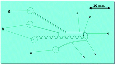
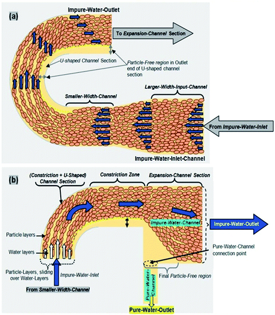
In the proposed novel device, a network of interconnected microfluidic channels was created so that an amalgamation of hydrodynamic effects, for instance the Fåhræus effect, centrifugal force, the Zweifach–Fung effect and constriction followed by expansion, are acting together on the microchannel, which may separate the suspended impurities (i.e. small dust particles, bacteria, fungi, viruses and similar particles present in water in the suspension form) from water, as presented in Fig. 1.The Fåhræus effect6,8 says that a decrease in the width of a microchannel will lead to decrease in the average concentration of impurities present in water. In this device, the input microchannel width of 300 μm is gradually decreased to 150 μm, which may result in the reduction of the average concentration of impurities present in water (Fig. 1 and 2a).
It was experimentally observed that the viscosity rises with the increase in the channel diameter and reaches an asymptotic score at channel diameters higher than around 0.5 mm. This is referred to as the Fåhræus–Lindqvist effect.6,9 As the dirty water flows through the channel, the suspended impurities tend to rotate and move towards the centre of the channel, which causes a suspended particle-free layer to exist close to the wall. In a channel with a miniature diameter, the region of the suspended particle-free zone is equivalent to the middle core. The final consequence of the suspended particle-free zone with a lower viscosity (the viscosity of water alone) is to decrease the evident viscosity of the flow via the microchannel. However, as the channel diameter increases, the result of the suspended particle-free zone minimizes and the viscosity coefficient tends towards the asymptotic score.
In the impure water, the majority of suspended particles naturally flow to the middle section of the channel. As the suspended particles move to the middle area of the channel, a marginal suspended particle depleted layer is created next to the channel wall. When the diameter of the channel decreases, the suspended particle-free region increases and the suspended particle region decreases. The separation efficiency of microchannel devices might be supposed to be a linear function of the deepness of the suspended particle reduced or depleted layer.
The particles (impurities) present in water in the suspension form experience the centrifugal action at the region of the completely semicircular, U-shaped curved microchannel section of the device (Fig. 2a). It is a much stronger force (compared to a partial 90° arc-like bend structure), which pushes the suspended particles (impurities) to the outer wall of the microchannel, because centrifugal force is directly proportional to the particle’s mass and inversely proportional to the radius of the curvature of the circular segment of the channel.9
An abrupt expansion in the microchannel, following the constriction, allows particles to progress in the fast axial flow whereas the particle-free water proceeds in the moderate marginal stream. Therefore, the normal velocity of the particles is superior to that of the particle-free water. The disparity in the velocities of the particles and the particle-free water increases with the decrement in the microchannel size in the constriction zone (Fig. 2b) resulting in the increase in the momentum of the particles. At the end of the U-shaped constriction section (Fig. 2b) there is an abrupt expansion region (after the constriction zone) in the pathway of flow, which offers a wider range of trajectories to the particles (owing to their superior momentum), in comparison to the particle-free-water, which propels the particles further than the pure water microchannel (width = 100 μm) outlet point by forming a particle-free zone.
Prominently, it also exhibits the Zweifach–Fung effect for suspended particle separation. This effect posits that when a suspended particle reaches a bifurcation region, the suspended particle has a propensity to pursue the elevated flow rate channel. Hence, when a suspended particle reaches the junction region between the expanded impure water microchannel and the pure water microchannel, the suspended particle has a propensity to pursue the elevated flow rate of the impure water microchannel.
The overall thickness (height) of the micro-channel (a network of interconnected microfluidic channels) was kept at 100 μm. All of the aforementioned physical effects impart a collective effect and are utilized together for the separation of suspended impurities (particles) from the contaminated water.
2.1. Microdevice physical attributes
The proposed microdevice was analyzed for its competence in separating the suspended bacterial cells from water. A few of the different physical parameters reflecting the quality of these devices discussed in this study are highlighted below.| ΔP = Q × R | (1) |
| Pmet − Patm = QP × RP = Qi × Ri | (2) |
In this equation, Pmet and Patm represent the pressures caused at the meeting point (of the impure water channel and the pure water channel) and the outlet, respectively. Furthermore, the flow rates of the inlet bacteria-contaminated impure water and pure water are represented by the quantities Qi and Qp, respectively. The fluidic resistances of the impure water inlet channel and pure water channel are given by Ri and Rp, respectively.
 | (3) |
In this equation, L, h and w represent the length, depth and width of any given section of the channel, respectively, and μ represents the viscosity of the impure/pure water. By modulating the fluidic resistance ratio of the impure water inlet channel and the pure water channel, the flow rate ratio at the bifurcation can be tuned according to the requirements. The pure water channel outlet and impure water channel outlet are at normal atmospheric pressure. By employing eqn. (2) and (3), the proportions of the device structure (shown in Fig. 1 and 2) were determined.
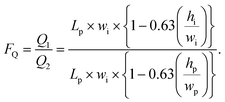 | (4) |
In this equation, Lp and wp represent the length and width of the pure water microchannel, respectively, and Li and wi represent the parallel magnitudes for the impure water channel.
 | (5) |
 | (6) |
In this equation, Ci = count of bacterial cells per ml in the impure water inlet channel and Cp = number of bacterial cells per ml in the bacterial cell depleted branch or pure water channel outlet.
3. Device design and fabrication
3.1. Materials used
SU8-50 was purchased from MicroChem USA, PDMS (polydimethylsiloxane) elastomer (Sylgard 184) was purchased from Dow Corning and Gram-negative E. coli MTCC (ATCC 25922) was purchased from the Institute of Microbial Technology (Chandigarh, India).3.2. Device fabrication
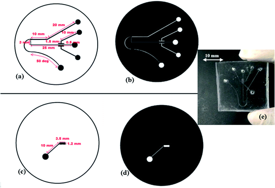
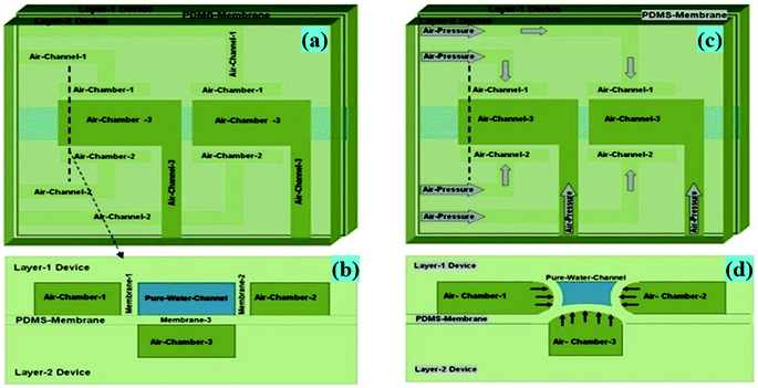
The proposed microfluidic device (Fig. 1 and 2) was fabricated using a multilayer soft lithography method with PDMS polymer. The device consists of two layers i.e. Layer-1 for the micro-scale dimension fluidic channel and side air chamber (1 & 2) arrangements, and Layer-2 for the upper air chamber (3) microstructures. In Layer-1, the fluidic input microchannel width is 300 μm and this was further gradually decreased to 150 μm, and a perpendicular channel (pure water channel) has a width of 200 μm in the design, along with a constriction–expansion zone. In the aforesaid arrangement, the air chamber (1 & 2) arrangements are two-valve compartments of a rectangular shape with a length of 1000 μm and breadth of 500 μm, which are formed along the pure water channel in Layer 1. The upper air chamber (3) microstructure is the upper-valve compartment of the rectangular shape with a length of 1000 μm and breadth of 500 μm.To form Layer 1 and Layer 2 of the fabricated device, two SU-8 masters were created using a standard photolithographic process,10–13 which provided a template for PDMS casting. The general steps for the single-stage photolithography process, i.e. (i) the spin coating of the SU-8 photoresist over a selected wafer, (ii) the pre-exposure bake, (iii) the exposure of the SU-8 photoresist to UV light under the designed UV-photo-mask for the Layer 1 and Layer 2 SU-8 masters (Fig. 3a–d), (iv) the post-exposure bake, (v) development and (vi) rinse drying, were performed to create the SU-8 masters for the Layer 1 and Layer 2 microstructures of the device. Then, Layer-1-microstructures and Layer-2-microstructures were fabricated by a soft lithography process.
For this purpose, the mixture with a 10![[thin space (1/6-em)]](https://www.rsc.org/images/entities/char_2009.gif) :
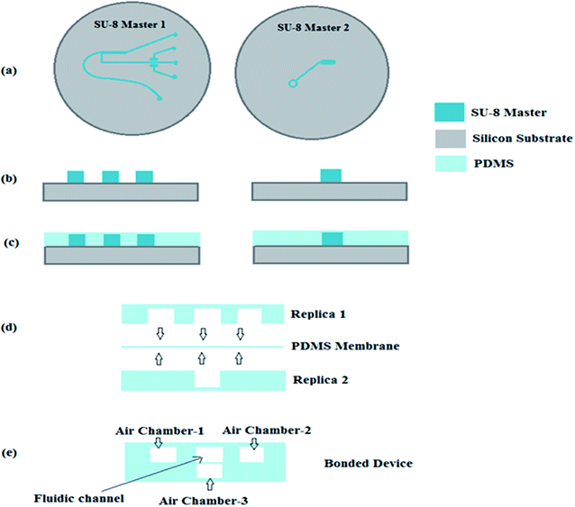
:![[thin space (1/6-em)]](https://www.rsc.org/images/entities/char_2009.gif) 1 ratio of PDMS pre-polymer and its curing agent was pour-casted on the two different SU-8 masters (Fig. 4b) created for Layer 1 and Layer 2 and then cured at 80 °C for 30 minutes (Fig. 4b and c).
1 ratio of PDMS pre-polymer and its curing agent was pour-casted on the two different SU-8 masters (Fig. 4b) created for Layer 1 and Layer 2 and then cured at 80 °C for 30 minutes (Fig. 4b and c).
A thin PDMS membrane of 50 μm thickness was also prepared via the spin-coating of a mixture of PDMS pre-polymer and its curing agent (in a ratio of 10![[thin space (1/6-em)]](https://www.rsc.org/images/entities/char_2009.gif) :
:![[thin space (1/6-em)]](https://www.rsc.org/images/entities/char_2009.gif) 1) over a silicon wafer and semi-curing at 80 °C for 30 minutes. Schematic diagrams of the aforesaid fabrication method are shown in Fig. 4 and 5.
1) over a silicon wafer and semi-curing at 80 °C for 30 minutes. Schematic diagrams of the aforesaid fabrication method are shown in Fig. 4 and 5.
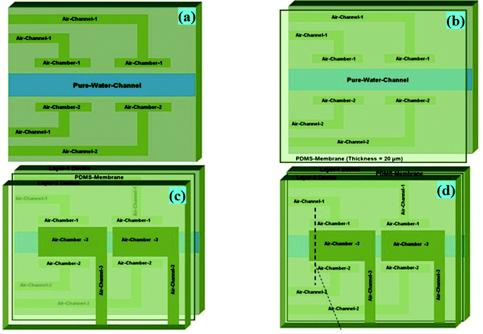 | ||
| Fig. 5 (a) Schematic diagram of Layer-1 of the device, where two points of the pure water channel of the device shown earlier (Fig. 1) were designed, having an encircled triple-sided film valve arrangement. Layer-1, Layer-2 and a thin PDMS membrane of the device were fabricated by a soft lithography process. (b) Layer-1 of the device was bonded with a thin PDMS membrane via a custom made plasma arc method. (c) The membrane side of the bonded device was again bonded to the air-channel/chamber side of Layer-2 of the device via a plasma arc method to create the final device. (d) The fabricated final microdevice's pure water channel structure, having an encircled triple-sided film valve arrangement. | ||
As presented in Fig. 4d and 5b, Layer-1 of the device was initially bonded with a thin PDMS membrane via a custom made plasma arc method. Then, the membrane side of the bonded device was again bonded to the air-channel/chamber side of Layer-2 of the device via a plasma arc method (Fig. 4e, 5c and d) to produce the final device.
4. Experimental setup
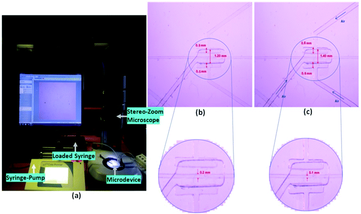
The experimental setup for the characterization of the device is presented in Fig. 7. The inlet and the outlet ports of the fabricated device were connected to the syringe pump (filled with the sample) and to the collection reservoir, respectively, via silicone tubes. Another syringe pump was connected to the inlets of the three air chambers (i.e. one on the upper and two at both sides of the pure water channel), through three silicone tubes, intended for pumping the air to the air chamber to inflate them by air pressure (of 10 psi) during the experimental procedure (Fig. 6 and 7). The schematic diagram (Fig. 6(a and b)) and image (Fig. 6(c and d)) of the air valve chamber are shown without and with air inflation, respectively.4.1. Sample preparation
Generally, the size of the microbial population in different kinds of sewage samples, i.e. in hospital effluents and municipal wastewater, ranges from 0.5 × 10³ to 2.9 × 10⁶ CFU ml−1 and from 2.2 × 10⁵ to 1.3 × 10⁸ cells per ml, respectively.14 Hereby, we targeted our experiments using bacterial counts in the water samples ranging from 2.05 × 10⁷ cells per ml to 1.5 × 10⁸ cells per ml obtained via our regular in-house bacterial culture process.The bacterial water was used as the sample in the experiment. The bacterial solution was prepared by inoculating bacteria from the strain in Luria broth. The sample was prepared by mixing the bacterial solution with water in the ratio of 1![[thin space (1/6-em)]](https://www.rsc.org/images/entities/char_2009.gif) :
:![[thin space (1/6-em)]](https://www.rsc.org/images/entities/char_2009.gif) 9. Using an UV–vis spectrophotometer (Ocean Optics), the optical density measurement of the prepared sample was done in order to calculate the concentration of the bacterial cells using eqn (7).15
9. Using an UV–vis spectrophotometer (Ocean Optics), the optical density measurement of the prepared sample was done in order to calculate the concentration of the bacterial cells using eqn (7).15
Concentration = ![[thin space (1/6-em)]](https://www.rsc.org/images/entities/char_2009.gif) OD600 × 0.8 × 109 cells per ml OD600 × 0.8 × 109 cells per ml
| (7) |
5. Results and discussion
The investigations using infected water samples with bacterial counts ranging from 2.05 × 10⁷ cells per ml to 1.5 × 10⁸ cells per ml have been carried out with and without the air-inflated/activated valves in the pure water channel. Also, experiments have been carried out for flow rates in the range of 0.15 to 1.0 ml min−1.First, a few introductory examinations were performed to check the separation efficiency of the microdevice. These investigations showed that at a low flow rate of ≤0.1 ml min−1, the separation efficiency was quite reduced. By further increasing the flow rate to 0.15 ml min−1 and above, the separation process was realized. With the additional increase of the flow rate up to 1.0 ml min−1, a trivial boost in the efficiency of separation was observed. Hence, the range of flow rates for further experiments was kept between 0.15 to 1.0 ml min−1.
Subsequent to passing the bacterial solution (i.e. impure/infected water) through the proposed device, a significant depletion of the bacterial population was observed in the pure water channel. The depletion of the bacterial population was indirectly proven via the observed change in the optical absorbance peaks of the pure/impure water in the pure water channel and impure water channel. Then, this was corroborated by the bacterial count of the output water from the pure water channel via the serial dilution method.
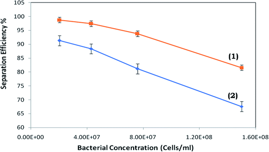
It was observed that at a lower bacterial concentration (i.e. 2 × 10⁷ cells per ml), the separation efficiency was almost 100%. Upon increasing the bacterial concentration to ∼7.6 × 10⁷ cells per ml and higher (Fig. 8), a proportionally rising propensity for bacterial cells to stream into the pure water microchannel was realized.
It may be anticipated that upon increasing the flow rate from the lowest value, the bacterial cell-free area may enlarge (Fig. 2) and the bacterial cells may possibly not move into the pure-water microchannel.
However, above a critical flow rate, there is a rise in the number of cells moving into the pure water microchannel. The potential reasons for this are presented later in the study. The separation efficiency of the device (with inflated/non-inflated valves) vs. the inlet bacterial cell concentration is presented in Fig. 8.
Throughout the investigation, it was perceived that, as the flow rate was increased, the strength of the vortices produced in the expansion section enhances, which modulates the water stream in the pure water microchannel; consequently, an examination was performed to discover the connection between the flow rate and flow ratio (volume flow rate in main channel/volume flow rate in plasma channel). Fig. 9 presents the flow rate against flow ratio for the arrangement of microchannels with and without the inflation of the triple-sided film valves of the pure water channel. It was observed that an inverse proportionality relationship exists between these two variables. Fig. 9 indicates that the flow ratio decreases with the increase in the input flow rate. Also, it emerged that the yield% was elevated at higher flow rates (Fig. 10).
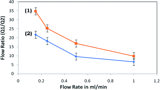 | ||
| Fig. 9 Flow ratio versus flow rate for the microdevice with (1) the activated and (2) non-activated triple-sided film valve. | ||
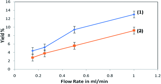 | ||
| Fig. 10 Yield% of the proposed device versus flow rate for the microdevice with (1) the activated and (2) non-activated triple-sided film valve. | ||
To investigate the separation efficiency observed with the activated and non-activated triple-sided film valve, the results in Fig. 8 are presented, which indicate that the separation efficiency (of the suspended bacterial cells in water) with the activated triple-sided film valve is much improved than with the non-activated valve. Additionally, a significant difference in the maximum possible separation efficiency was realized at all bacterial concentrations between the activated and non-activated triple-sided film valve.
The highest effectiveness was not shown to be at the same flow rate with both the activated and non-activated triple-sided film valve of the microdevice, however, there is a minor flow rate reliance. This is because of the discussed association between the flow ratio and flow rate (Fig. 9).
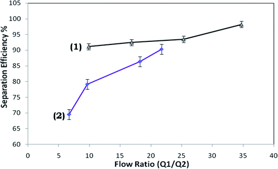
Fig. 11 presents the connection between the separation efficiency and flow ratio. This suggests the minor dependence of the separation efficiency on the flow ratio and we may obtain 100% efficiency for 2 × 10⁷ cells per ml in the case of the device with the activated triple-sided film valve. It can be observed from Fig. 11 that the separation efficiencies for 2 × 10⁷ cells per ml vary with the flow ratio and at an optimum flow ratio the separation efficiency is maximized.
In general, with the increasing initial flow ratio, an increment in the bacteria separation efficiency was observed, followed by a decrement in the efficiency slope.
Since the centrifugal force is straightforwardly relative to the mass of the particle, heavier particles experience more grounding power than lightweight particles and are pushed more towards the outer bend walls of the U-bend channel region than their lighter partners. This leads to a smaller probability of the heavier bacterial cells entering into the inner pure water channel.
In the case when the valve was inflated by air pressure using a syringe pump, the constriction of the pure water channel occurred, giving rise to the enhanced channel resistance, which finally affects the flow ratio of the device, causing the enhanced efficiency.
Throughout the experimental process, it was seen that the separation efficiency increased as the flow rate rose from the minimum to 0.15 ml min−1. It was expected that the efficiency would constantly be enhanced upon increasing the flow rate as the bacterial cell free area (Fig. 2a and b) continues to grow with higher flow rates. However, only a few flow rates were seen where a higher separation efficiency could be obtained. Obviously, the flow rate range of 0.15 to 0.5 ml min−1 was observed to be the most favourable flow rate for achieving the highest potential efficiency for the given design. Furthermore, elevated separation efficiencies were achieved at lower bacterial cell concentrations, but as the cell concentration increased, the separation efficiency reduced due to a rise in the number of bacterial cells.
The centrifugal force propels the bacterial cells with higher density around the outer wall of the microchannel (Fig. 2a and b) while water, with a lower density, is thrust towards the inner wall of the microchannel. Also, the velocity at the outer wall is more than the velocity at the inner wall. Since the velocity gradient is elevated in a microchannel with a smaller diameter, this may lead to a stronger vortex. Hence, higher separation efficiencies are expected in the devices. However, it has been observed that, as the flow rate increases, the strengths of the vortices are higher in the devices. Therefore, although the cell free region may be larger in the microchannels, the separation efficiency is found to not be higher at very high flow rates, compared to optimal flow-rates. This is also apparent from the values of the calculated flow ratio (Fig. 9). It can be observed that at an identical flow rate, the flow ratios measured in the devices with activated valves were significantly higher than those for the non-activated valve devices and this big disparity is possibly due to the power of the vortex created and the increased resistance of the pure water microchannel.
6. Conclusion
A microdevice for the separation of suspended bacterial cells is offered in this study and, compared to our earlier reported study,9,16 the presented microdevice effectively contains an additional triple sided film valve (in the pure water channel) along with different hydrodynamic separation characteristics in a single device (with a much higher microchannel cross-section area) in a creative and condensed manner. The additional triple sided film valve helps to manage and modulate the flow ratio in a controlled manner, which aids in enhancing the separation efficiency of the device. Consequently, it supersedes the available prior example in different aspects.The microdevices investigated by previous researchers have microchannel dimensions similar to the dimensions of the separated particles i.e. blood cells in these studies,8,17,18 and only few researchers have used a higher density of separated particles to establish their device design. Due to the smaller microchannel cross-sectional area of the microdevices proposed previously, their production needs microfabrication processes with greater precision and precise laboratory environments. The bonding procedure is required to be performed via oxygen plasma bonding, which requires costly instruments (i.e. an oxygen plasma asher) as it cannot be executed via applying semi-cured PDMS as an adhesive layer.9,16 Consequently, the general fabrication procedure is pricey and needs accurate equipment with a particular laboratory environment. However, owing to the larger cross-sectional area of the microchannel in the proposed device, its production needs a microfabrication procedure with regular accuracy and general laboratory conditions. Other low-cost methods, i.e. hot embossing, micromachining and laser ablation, may too be used for its production. The microchannel bonding method may be effortlessly executed via applying a semi-cured PDMS layer as a bonding agent,9,16 rather than using a costly oxygen plasma asher; therefore, the general manufacturing procedure becomes low-cost.
In the innovatively designed proposed microdevice, its different microfluidic components, performing respective hydrodynamic effects (i.e. the Fåhræus effect, centrifugal force, Zweifach–Fung effect and constriction followed by expansion), are connected compactly with a small device area and cumulatively displayed effective separation for the real-time separation of the water medium from an aqueous suspension of bacterial cells. Previously reported studies have utilized various hydrodynamic effects to separate plasma from blood samples (i.e. suspensions of blood cells),9,16–18 however, in our present work, we envisaged separating water from the suspension of much smaller particles (i.e. bacterial cells) in water via much enhanced hydrodynamic effects. For the enhancement of the hydrodynamic effects, a novel triple sided membrane valve was used, which aided the reduction of the cross-sectional area of the pure water channel, which further gave rise to the increased Zweifach–Fung effect, leading to the better separation efficiency. The observed average separation efficiency of our proposed system to remove the liquid (i.e. water) from the suspension is 99.6%.
Gachelin et al.19 have reported the non-Newtonian behaviour of E. coli suspensions (of 1.9× 10¹² cells per litre) and the equivalent density (i.e. 1.5 × 10⁸ cells per ml) of the bacterial cell suspension used in our experiments showed a very similar effect. The lower cross-sectional area of the microchannels of previously reported microdevices8,17,18 make them greatly vulnerable to congestion through bonding or the particle separation process. Our current effort is therefore a significant stride regarding rectifying the aforesaid matter straightforwardly and efficiently.
The proposed device and process may be applied to analogous particle separation purposes in different domains of chemistry, biology, medicine, environmental science, etc., after minor adjustments to the design and process. It may be utilized at industrial scales, also, via the coupling together of multiple equivalent microdevices units in parallel and passing the water sample through them in parallel to enhance the volume of water decontaminated per unit time. However, at an industrial scale, the pretreatment of a substantially contaminated water sample may be needed via general methods (i.e. via the gravitational settling of large particles) because a dense suspension of water contaminants (with a contaminant size larger than the microchannel diameter) may block the microchannel during its passage. Hereby, a possible minor modification in the microdevice design and process is required for applying this technology at the industrial scale.
In the domain of the chemical sciences, during chemical synthesis processes, there is often a need to separate the soluble product mixtures from suspended product particles existing within the synthesized chemical suspension. Generally, the centrifugation process is used to separate the products of chemical synthesis into pellet (insoluble) and supernatant (soluble) fractions. Considering that the centrifugation process is bulky, time consuming and requires costly instrumentation, the proposed microdevice may also be a potential alternative for similar applications, owing to its compact size, cost-effectiveness and the facility of real-time separation. Furthermore, the proposed microdevice may also be coupled within an innovatively designed microfluidic-reactor machinery as a tool for the real-time separation of synthesized soluble and insoluble product mixtures following chemical synthesis processes occurring within micro-reactors.
A microfluidic biosensing unit may also be incorporated in the pure water microchannel of the device (considering the molecule or ion of interest in the water), which may provide an inclusive, condensed and handy biosensing device. Several microfluidic biosensor components may instantly interact with the pure water output from the proposed bacterial/particle separation device. The interference in biosensing due to particles/bacterial cells being present in the water may be minimized and the device may be directed towards the detection of organic/inorganic contaminants present in water. It may also show the simultaneous disparity in the concentration of the molecules or ions of interest in the output water (i.e. organic/inorganic contaminants present in the water). Consequently, it would be mostly simple to incorporate an optical evanescent wave absorbance or LSPR-oriented microfluidic biosensor10–12,20,21 component in the proposed particle/bacterial cell separation microfluidic element in a single microfluidic biosensor design. Positively, the combination of this proposed particle/bacterial cell separation microfluidic unit with a suitable microfluidic biosensing unit would improve its analytical relevance and improve the extent of its potential applications. In the future, we could also investigate a process to additionally modulate the dimensions of the microchannel arrangement and triple-sided membrane valves, which may effectively aid in eliminating virus (i.e. coronavirus) particles suspended in water.
Funding
The authors recognize the financial support from the following sponsoring organizations: (1) the Department of Science and Technology (DST) with grant number: DST/TM/WTI/2K15/201, (2) the Science & Engineering Board (SERB) with grant number: SR/FTP/ETA-0126/2014 and (3) the UGC-FRP Start-UP Grant.Conflicts of interest
There are no conflicts to declare.Acknowledgements
The authors acknowledge the financial support from the Department of Science and Technology (DST) with grant number: DST/TM/WTI/2K15/201, the Science & Engineering Board (SERB) with grant number: SR/FTP/ETA-0126/2014 and the UGC-FRP Start-UP Grant.References
- S. Sharma and A. Bhattacharya, Drinking water contamination and treatment techniques, Appl. Water Sci., 2017, 7(3), 1043–1067 CrossRef CAS.
- Global Issues in Water, Sanitation, and Health, Institute of Medicine (US) Forum on Microbial Threats, Washington (DC), National Academies Press (US), Workshop Overview, 2009, URL: https://www.ncbi.nlm.nih.gov/books/NBK28449 Search PubMed.
- Process water treatment, URL: https://www.waterprofessionals.com/process-water/ Search PubMed.
- J. Zhang, S. Yan, R. Sluyter, W. Li, G. Alici and N. Nguyen, Inertial particle separation by differential equilibrium positions in a symmetrical serpentine micro-channel, Sci. Rep., 2015, 44527 Search PubMed.
- M. Yamada, M. Nakashima and M. Seki, Pinched flow fractionation: Continuous size separation of particles utilizing a laminar flow profile in a pinched microchannel, Anal. Chem., 2004, 76(18), 5465–5471 CrossRef CAS PubMed.
- S. Tripathi, A. Prabhakar, N. Kumar, S. G. Singh and A. Agrawal, Blood plasma separation in elevated dimension T-shaped microchannel, Biomed. Microdevices, 2013, 15(3), 415–425, DOI:10.1007/s10544-013-9738-z.
- P. Peduzzi and B. Luef, Viruses, bacteria and suspended particles in a backwater and main channel site of the Danube (Austria), Aquat. Sci., 2008, 70(2), 186–194 CrossRef PubMed.
- A. I. Rodríguez-Villarreal, M. Arundell, M. Carmona and J. Samitier, High flow rate microfluidic device for blood plasma separation using a range of temperatures, Lab Chip, 2010, 10, 211–219 RSC.
- A. Prabhakar, Y. V. B. Varun Kumar, S. Tripathi and A. Agrawal, A novel, compact and efficient microchannel arrangement with multiple hydrodynamic effects for blood plasma separation, Microfluid. Nanofluid., 2015, 18(5–6), 995–1006 CrossRef CAS.
- A. Prabhakar and S. Mukherji, Microfabricated polymer analysis chip with integrated U- bend waveguides for evanescent field absorption detection, Lab Chip, 2010, 10, 748–754 RSC.
- A. Prabhakar and S. Mukherji, Investigation of the effect of curvature on sensitivity of bio/chemical sensors based on embedded polymer semicircular waveguides, Sens. Actuators, B, 2012, 171–172, 1303–1311 CrossRef CAS.
- A. Prabhakar, N. Mishra and S. Mukherji, A Comprehensive Investigation of a Microfabricated U Bend Polymer Waveguide With Analyte Micro Reservoir for Versatile On-Chip Sensing Applications, J. Microelectromech. Syst., 2017, 26, 935–945 CAS.
- A. Prabhakar, M. Agrawal, N. Mishra, N. Roy, A. Jaiswar and A. Dhwaz, Cost-effective smart microfluidic device with immobilized silver nanoparticles and embedded UV-light sources for synergistic water disinfection effects”, RSC Adv., 2020, 10, 17479–17485 RSC.
- E. Korzeniewska and M. Harnisz, Culture-Dependent and Culture-Independent Methods in Evaluation of Emission of Enterobacteriaceae From Sewage to the Air and Surface Water, Water, Air, Soil Pollut., 2012, 223(7), 4039–4046, DOI:10.1007/s11270-012-1171-z.
- J. Wang, M. Woo and C. Yan, Spot Plating Assay for the Determination of Survival and Plating Efficiency of Escherichia coli in sub-MIC Levels of Antibiotics, JEMI Methods, 2017, 1, 26–29 Search PubMed.
- S. Tripathi, Y. V. B. V. Kumar, P. Amit, S. Joshi and A. Agrawal, Synthesis of bio- physical and geometrical effects for developing a microdevice for plasma separation from whole human blood, Sci. Rep., 2016, 6, 26749 CrossRef CAS PubMed.
- S. Yang, A. Undar and J. D. Zahn, A microfluidic device for continuous, real time blood plasma separation, Lab Chip, 2006, 6, 871–880 RSC.
- C. Blattert, R. Jurischka, I. Tahhan, A. Schoth, P. Kerth and W. Menz, Separation of blood in microchannel bends, Conference proceedings : Annual International Conference of the IEEE Engineering in Medicine and Biology Society. IEEE Engineering in Medicine and Biology Society. Annual Conference, 2004, 1, 2627–2630 Search PubMed.
- J. Gachelin, G. Miño, H. Berthet, A. Lindner, A. Rousselet and É. Clément, Non-Newtonian viscosity of E-coli suspensions, Phys. Rev. Lett., 2013, 110, 268103 CrossRef.
- A. Prabhakar, N. Mishra, D. Verma and S. Mukherji, Investigation of Dual Bend - Serpentine/Spiral Waveguides, Coupled to Microchannel System, for Competent, Evanescent Wave Absorption Based, On-Chip, Biological/Chemical Sensing Applications, RSC Adv., 2018, 8, 35539–35550 RSC.
- A. Prabhakar and S. Mukherji, A novel C-shaped, gold nanoparticle coated, embedded polymer waveguide for localized surface plasmon resonance based detection, Lab Chip, 2010, 10, 3422–3425 RSC.
| This journal is © The Royal Society of Chemistry 2021 |

