 Open Access Article
Highly conductive locust bean gum bio-electrolyte for superior long-life quasi-solid-state zinc-ion batteries†
Binbin Liua,
Yuan Huang*b,
Jiawei Wanga,
Zixuan Lia,
Guoshen Yanga,
Shunyu Jinc,
Emad Iranmanesha,
Pritesh Hiralal*d and
Hang Zhou *a
*a
aSchool of Electronic and Computer Engineering, Peking University Shenzhen Graduate School, Shenzhen, 518055, PR China. E-mail: zhouh81@pkusz.edu.cn
bSchool of Microelectronics Science and Technology, Sun Yat-Sen University, Guangzhou, PR China. E-mail: huangy723@mail.sysu.edu.cn
cCenter for Micro- and Nanoscale Research and Fabrication, University of Science and Technology of China, Hefei, 23000, PR China
dZinergy Shenzhen Ltd., Gangzhilong Science Park, Longhua, Shenzhen, 518109, PR China. E-mail: pritesh@zinergy-power.com
First published on 16th July 2021
Abstract
Rechargeable aqueous zinc-ion batteries (ZIBs) are promising wearable electronic power sources. However, solid-state electrolytes with high ionic conductivities and long-term stabilities are still challenging to fabricate for high-performance ZIBs. Herein, locust bean gum (LBG) was used as a natural bio-polymer to prepare a free-standing quasi-solid-state ZnSO4/MnSO4 electrolyte. The as-obtained LBG electrolyte showed high ionic conductivity reaching 33.57 mS cm−1 at room temperature. This value is so far the highest among the reported quasi-solid-state electrolytes. Besides, the as-obtained LBG electrolyte displayed excellent long-term stability toward a Zn anode. The application of the optimized LBG electrolyte in Zn–MnO2 batteries achieved a high specific capacity reaching up to 339.4 mA h g−1 at 0.15 A g−1, a superior rate performance of 143.3 mA h g−1 at 6 A g−1, an excellent capacity retention of 100% over 3300 cycles and 93% over 4000 cycles combined with a wide working temperature range (0–40 °C) and good mechanical flexibility (capacity retention of 80.74% after 1000 bending cycles at a bending angle of 90°). In sum, the proposed ZIBs-based LBG electrolyte with high electrochemical performance looks promising for the future development of bio-compatible and environmentally friendly solid-state energy storage devices.
1. Introduction
Rechargeable aqueous zinc-ion batteries (ZIBs) are promising candidates for use in wearable electronics due to their high safety, environmental friendliness, low-cost, and abundant natural resources.1–5 However, ZIBs still suffer from issues related to electrolyte leakage, dendrite formation, inevitable corrosion, and inferior reversibility of Zn anodes in aqueous electrolytes.2–4,6–14 As a result, tremendous efforts have been devoted to finding novel solid-state electrolytes. To this end, numerous polymers have been synthesized, including, but not limited to, polyvinyl alcohol (PVA)/ZnCl2,15 PVA–COOH/Zn(NO3)2,16 polyacrylamide (PAM)/ZnSO4,17 PAM/gelatin/ZnSO4,18 PAM/sodium alginate/ZnSO4,19 polyzwitterionic/ZnSO4,8 zwitterionic sulfobetaine/cellulose/ZnSO4,20 and zinc perfluorinated sulfonic acid membrane (ZPSAM).4 Nonetheless, the preparations of synthetic polymers from monomers are often complex. Besides, some organic solvents utilized during the synthesis are poisonous, impeding large-scale industrial fabrication and safe usage.Compared to synthetic polymers, natural bio-polymers are non-toxic, cost-effective, and biocompatible. Therefore, they are increasingly considered for utilization as electrolytes of ZIBs. Examples include xanthan gum,21 kappa-carrageenan,22 gelatin,23 guar gum,24 and sodium alginate.6 Such zinc-ion quasi-solid-state electrolytes based on bio-polymers often possess elevated ionic conductivities (10−2 S cm−1) and high flexibility. Nevertheless, they still suffer from several problems. For instance, kappa-carrageenan electrolyte suffers from low mechanical strength.22 By comparison, the cycling performances of ZIBs assembled with xanthan gum, gelatin, and sodium alginate electrolytes are still unsatisfactory.
Locust bean gum (LBG) is a natural bio-polymer widely used in food, biopharmaceuticals, paper, and cosmetics.25–27 Besides, LBG can be employed as a water-soluble binder for LiFePO4 and Li4Ti5O12 electrodes in lithium-ion batteries.28 LBG is a galactomannan extracted from seeds of carob trees. The galactomannan is high-salt-tolerant with the ability to form uniform systems with zinc sulfate salt. LBG may induce strong hydrogen bonding to lock water molecule,26,29 thereby can reduce ice-crystal formation at decreased temperatures.26 Additionally, LBG could form viscous hydrogels at low concentrations. These features make LBG suitable for use as a solid electrolyte matrix. However, no reports dealing with its use as the solid-state electrolyte for energy storage have so far been published.
Herein, LBG was utilized to fabricate a free-standing quasi-solid-state ZnSO4/MnSO4 electrolyte. The ionic conductivity of the as-obtained LBG electrolyte at room temperature reached 33.57 mS cm−1. This value was the highest reported so far for ZIBs. Besides, Zn2+ ions diffused only within a confined domain of LBG quasi-solid-state electrolyte, thereby inhibiting dendrite formation on Zn anode and improving the long-term stability of LBG electrolyte toward Zn anode. Zn–MnO2 batteries assembled with LBG electrolyte delivered excellent electrochemical performance.
2. Material and methods
2.1 Preparation of LBG electrolyte
Firstly, 0.5 g locust bean gum (Aladdin) was dispersed in 10 mL aqueous solution containing 2 M ZnSO4 (AR grade, Aladdin) and 0.1 M MnSO4 (AR grade, Macklin) at room temperature. The resulting mixture was then poured into a film mold treated on a heating panel at 100 °C for 5 min. Next, the LBG electrolyte was solidified at room temperature.2.2 Preparation of MnO2/rGO cathode and Zn anode
The preparation of MnO2/rGO cathode was carried out first by mixing 70 wt% of α-MnO2 powder (obtained by the hydrothermal method),30 20 wt% of rGO (diameter 0.5–5 μm, thickness 0.8 nm, Nanjing/Jiangsu XFNANO Materials Tech Co., Ltd.), and 10 wt% of polyvinylidene fluoride (PVDF) in N-methyl pyrrolidone (NMP) under magnetic stirring for 4 h. The resulting slurry was then coated on the carbon cloth and dried at 70 °C for 6 h. The electrode area was estimated to ∼1.54 cm2, and the mass loading of active material was ∼2 mg cm−2.The electro-deposited Zn anode was obtained by electrodeposition of Zn on carbon cloth.15 To this end, the carbon cloth was used as the working electrode and Pt foil as both counter and reference electrode. The electrodeposition solution contained 2.5 g ZnSO4·7H2O, 2.5 g Na2SO4, and 0.4 g H3BO3 dissolved in 20 mL distilled water. The electrodeposition was then performed at a constant current density of −40 mA cm2 for 15 min at room temperature. The electrode area was 1.54 cm2, and the mass loading of zinc was ∼8 mg cm−2.
2.3 Structure and morphology characterization
The morphologies of the electrodes were examined by field-emission scanning electron microscopy (FESEM, Zeiss SUPRA-55). The Fourier transform infrared spectroscopy (FTIR) spectra of the samples were characterized by a Bruker Vertex 70 spectrometer. The crystalline phases of the samples were identified by X-ray diffraction (XRD, D8 Advance). ThermoGravimetric Analysis (TGA) was performed by using a simultaneous thermal analyser (MDTC-EQ-M05-01). Nitrogen adsorption/desorption isotherms and pore-size distributions were collected with an accelerated surface-area and porosimetry system (ASAP 2020 HD88). The contact angle was characterized by contact angle tester (DongGuan Precise Test Equipment Co., Ltd., PT-705B).2.4 Electrochemical testing
The ionic conductivities of LBG electrolyte were measured by placing a piece of LBG electrolyte film between two stainless sheets, followed by impedance measurements at frequencies of 10k to 0.01 Hz and alternating current (AC) amplitude of 5 mV using a CHI 660e (Shanghai CH Instrument). The conductivity values were calculated according to eqn (1):
 | (1) |
The corrosion current density (Icorr) values were calculated using eqn (2):
 | (2) |
Aqueous electrolytes of Zn/Zn symmetrical cells were assembled by separating the Zn foils by a separator (NKK separator, MPF30AC-100, Japan) in a solution containing 2 M ZnSO4 and 0.1 M MnSO4. The symmetric cells were tested at 0.2 mA cm2 using a multichannel battery test system (CT2001A, Wuhan Kingnuo Electronic Co., Ltd.). The linear sweep voltammetry (LSV) curves of LBG and aqueous electrolytes were obtained using stainless steel as the working electrode and Zn foil as both reference and counter electrode. The Tafel plots of LBG and aqueous electrolytes were collected using Zn foil as working electrode, Ag/AgCl as a reference, and Pt foil as a counter electrode. The cyclic voltammetry (CV) curves of Zn plating/stripping in LBG electrolyte were recorded using stainless steel as the working electrode and Zn foil as both reference and counter electrode.
The electrochemical properties of ZIBs assembled with LBG electrolyte were examined using MnO2/rGO as the cathode and the electro-deposited Zn as the anode. CV was conducted between 1.0 and 1.9 V vs. at a scanning rate of 0.5 mV s−1 on CHI660, Shanghai CH Instrument Co., Ltd. The galvanostatic charge/discharge cycles were tested at different current densities on a multichannel battery test system (CT2001A, Wuhan Kingnuo Electronic Co., Ltd.).
A constant temperature and humidity chamber (RHP-23, REALE) was used for the storage of the electrodes and cells.
3. Results and discussion
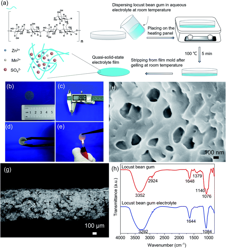
The molecular formula of the as-prepared LBG is shown in Fig. 1a. The molecule consisted of a linear backbone chain of D-mannopyranose units and side chains containing D-galactopyranose unit. In this structure, an average of one D-galactopyranose side unit was attached to four backbone D-mannopyranose units. Due to high-salt-tolerant and good water-soluble abilities, LBG is a wonderful host for zinc sulfate salt solution. The feasible preparation of a LBG bio-electrolyte is also provided in Fig. 1a, and details can be found in Material and methods Section. Before heat treatment, the locust bean gum was distributed uniformly in ZnSO4 + MnSO4 mixture electrolyte (Fig. S1, ESI†). After heat treatment, the uniform LBG electrolyte film showed a white color with thickness around 0.9 mm (Fig. 1b and c). Besides, the material displayed excellent flexibility and repeated bending ability (Fig. 1d), useful for applications of flexible ZIBs. Meanwhile, fire resistance is a very important feature of battery electrolytes. As shown in Fig. 1e, the LBG electrolyte did not catch fire when burned by a pocket lighter, demonstrating good water-holding capability. The PH value of LBG electrolyte is ∼4.The morphology of LBG electrolyte after drying was investigated by scanning electron microscopy (SEM). In Fig. 1f, the LBG electrolyte featured interconnected porous structures with pore sizes ranging from 50 nm to 300 nm. The cross-sectional SEM image of a dried LBG in Fig. 1g illustrated the presence of some large pores in the cross-section at the micrometer scale.
The amount of components in the LBG electrolyte was evaluated using ThermoGravimetric Analysis (TGA). As shown in Fig. S2 (ESI†), the weight loss below 200 °C was attributed to the loss of water.5 The weight loss to between 200 °C and 350 °C was due to the loss of crystalline water.31 The weight loss between 350 °C and 600 °C can be attributed to the loss of locust bean gum.32 The last remaining mass is inorganic salts. According to TGA analysis, the weight percentage of locust bean gum in gum electrolyte was ∼12.26%.
The specific surface area and the pore size distribution of the LBG electrolyte was investigated by Brunauer–Emmett–Teller (BET) measurement after the hydrogels were dried in vacuum oven. The microporous structure of LBG electrolyte was confirmed by N2 adsorption–desorption (Fig. S3a, ESI†). The specific surface area is 1.67 m2 g−1. The pore diameter distribution lay mainly in the range of 50–80 nm (Fig. S3b, ESI†), and the pore volume was 0.0198 cm3 g−1.
Fig. S4 (ESI†) shows the contact angle of the LBG electrolyte is about 0°, indicating the excellent wettability of the LBG hydrogels.
The FTIR spectra of pure LBG polymer (red line) and LBG electrolyte (blue line) are gathered in Fig. 1h. Pure LBG polymer exhibited peaks at ∼1076 and ∼1140 cm−1 attributed to C–O stretching vibration of glycosidic bonds and C–O bending vibration of pyranose rings, respectively.33,34 The peaks at around 1379 cm−1 were attributed to the CH2 and C–OH symmetrical deformation.33 The bands at ∼1648 cm−1 were assigned to ring stretching of galactose and mannose.35 The characteristic peaks at about 2924 cm−1 were associated with –CH2 bending/wagging, and those 3352 cm−1 were linked to O–H stretching of hydroxyl group.36 Compared to FTIR pure LBG polymer, the intensity of the peak near 1084 cm−1 of LBG electrolyte became dominant, directly linked to the existence of SO42–.21,22,24 The peak at ∼3292 cm−1 of –OH bending vibration became wider due to the presence of Zn2+ and Mn2+.21
The ionic conductivity (σ) data of LBG electrolyte are firstly verified. They were obtained by AC impedance spectroscopy. The experimental and calculation details of ionic conductivity of LBG electrolyte can be found in the Material and methods Section.
The AC impedance spectral data of LBG electrolyte (2 M ZnSO4 and 0.1 M MnSO4) at different temperatures are displayed in Fig. 2a, and calculated values are summarized in Table 1. The high ionic conductivity of LBG electrolyte at room temperature reached 33.57 mS cm−1. Compared to data of other reported zinc ion-conducting polymer electrolytes, LBG electrolyte showed the highest conductivity (Fig. 2b). The activation energy (Ea) of LBG electrolyte was obtained by linear fitting of the Arrhenius equation (eqn (3) and Fig. S5, ESI†):
 | (3) |
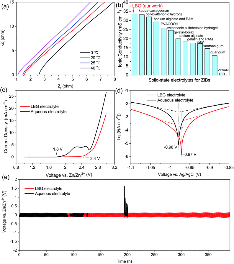 | ||
| Fig. 2 (a) AC impedance spectra of the LBG electrolyte at 0, 20, 25, 40 °C. (b) Comparison of the LBG electrolyte with other zinc-ion conducting polymer electrolytes in terms of ionic conductivity in the literature.4,6,8,16–24 (c) LSV curve of the LBG electrolyte and aqueous electrolyte. (d) Tafel plots of the LBG electrolyte and aqueous electrolyte. (e) Cycling performance of Zn/Zn symmetrical cell with the LBG electrolyte and aqueous electrolyte at 0.2 mA cm−2. | ||
| Temperature (°C) | Ionic conductivity (mS cm−1) |
|---|---|
| 0 | 18.59 |
| 20 | 31.19 |
| 25 | 33.57 |
| 40 | 44.03 |
The electrochemical properties of the LBG electrolyte are illustrated in Fig. 2c. Compared to the aqueous electrolyte (1.8 V), the LBG electrolyte displayed a higher electrochemical stability window of 2.4 V (vs. Zn/Zn2+), as shown by LSV. It is reported that the water shows an electrochemical stability window of −0.05 to 1.7 V versus Zn/Zn2+.7 The Zn plating reaction occurs at a voltage lower than ∼ −0.1 V and polarization current increases happened at a voltage higher than ∼1.8 V in aqueous solution.21 The corrosion behaviors of metallic Zn in aqueous electrolyte and LBG electrolyte are investigated by potentiodynamic polarization testing. The experimental and fitting curves are shown in Fig. 2d, and the calculation formula is provided in Material and methods Section. Note that more positive corrosion potential and lower corrosion current would lead to less tendency to corrosion reactions and low corrosion rates, respectively. Examples include typically induced hydrogen evolution and dissolved oxygen passivation.7 Compared to the corrosion potential of Zn in aqueous electrolytes (−0.98 V), the corrosion potential of Zn in LBG electrolyte shifted by 10 mV to reach −0.97 V. Meanwhile, the corrosion current of Zn in LBG electrolyte was only 0.12 mA cm−2, thereby significantly lower than that of Zn in aqueous electrolytes (1.75 mA cm−2). Thus, LBG electrolyte looked almost non-corrosive to zinc foil due to the water molecules locked along the locust bean gum polymer chains through strong hydrogen bond.26,29 Thus, LBG electrolyte created a highly-stable environment for metallic Zn electrodes.
The Zn plating/stripping behavior in LBG electrolyte was investigated by CV and the results are shown in Fig. S6 (ESI†). The Zn2+ ions started reducing to Zn at −0.13 V (vs. Zn/Zn2+), and metallic Zn dissolved at 0.29 V. The long-term stability of LBG electrolyte toward Zn anode was studied by galvanostatic cycling of Zn/Zn cells containing the LBG electrolyte and aqueous electrolyte at the current density of 0.2 mA cm−2. As shown in Fig. 2e, the Zn/Zn symmetrical cell assembled with LBG electrolyte showed excellent kinetics and stability of Zn stripping/plating. Besides, no sudden increase in polarization was observed even after 390 h of Zn stripping/plating. The coulombic efficiency during Zn2+ stripping/plating process was around 100%. (Fig. S7, ESI†) By contrast, the polarization of the aqueous electrolyte Zn/Zn symmetric cell during the zinc plating/stripping process looked much worse.
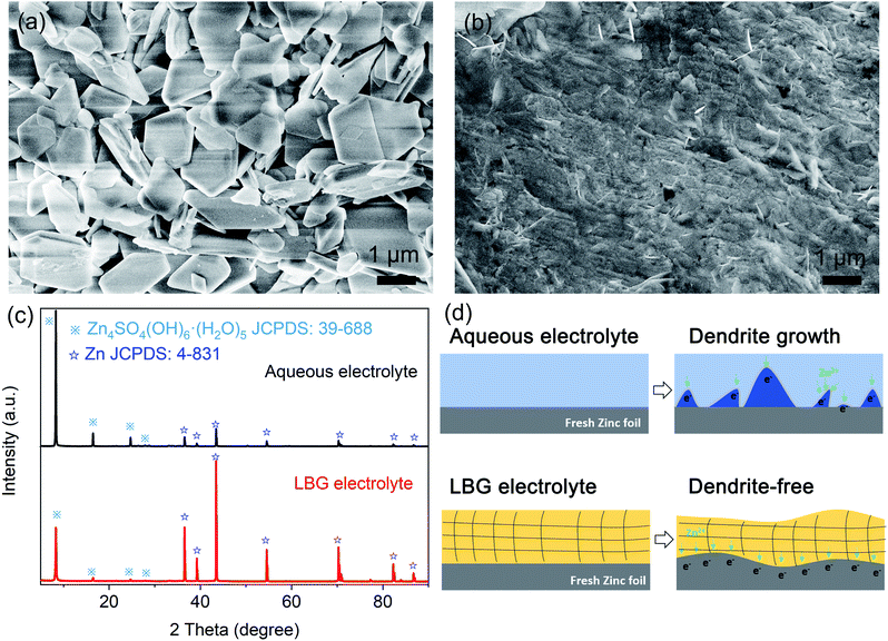
Dendrite formation in the aqueous electrolyte is challenging for the practical applications of ZIBs because non-uniform deposition would result in capacity decay and inevitable short-circuiting. To compare LBG to the aqueous electrolyte for Zn plating, further morphology characterization of Zn after long-term Zn stripping/plating was carried out (Fig. 3a and b). Compared to the morphology of pristine Zn foil (Fig. S8, ESI†), small slices were noticeable for Zn plated after long-term (120 h) by zinc plating/stripping process at 0.2 mA cm−2 in LBG electrolyte (Fig. 3b). By comparison, the surface of zinc foil after a long-term (120 h) zinc plating/stripping process at 0.2 mA cm−2 in an aqueous electrolyte displayed numerous bulgy bulks (Fig. 3a).
The composition of Zn foil anode after long-term (120 h) zinc plating/stripping process at 0.2 mA cm−2 in LBG and aqueous electrolytes were identified by XRD. In Fig. 3c, the diffraction peaks were well indexed to Zn (JCPDS: 4-831) and Zn4SO4(OH)6(H2O)5 (JCPDS: 39-688). Hence, Zn foil anodes after long-term zinc plating/stripping in LBG and aqueous electrolytes consisted of Zn metal and Zn4SO4(OH)6(H2O)5. The formation of zinc hydroxide sulfate was attributed to the increased concentration of OH− at the electrode/electrolyte interface due to the consumption of H+ from the electrolyte during discharge processes.5 Note that XRD peaks of Zn4SO4(OH)6(H2O)5 dominated the Zn foil in aqueous electrolyte after long-term zinc plating/stripping. By contrast, the peak intensity of Zn4SO4(OH)6(H2O)5 after long-term zinc plating/stripping weakened in LBG electrolyte. This can be explained by the strong hydrogen bonds anchoring water molecules in the LBG electrolyte.
Based on the above results, a schematic diagram of dendrite formation in different electrolytes was proposed in Fig. 3d. In an aqueous electrolyte, Zn2+ could freely move along the surface of metal zinc. During the initial process, Zn2+ absorbed on the surface aggregated at priority nucleation sites, further exacerbating to form tips under the uneven electric field distribution. This, in turn, induced considerable Zn dendrites on Zn foil surface. By comparison, dendrite formation on Zn anode was inhibited in LBG polymer electrolyte.
The good flexibility, high ionic conductivity, and long-term stability of LBG electrolyte toward Zn anode would make LBG electrolyte ideal for applications in quasi-solid-state ZIBs. Hence, quasi-solid-state ZIBs were assembled with LBG electrolyte in an open-air environment. To this end, α-MnO2 composite electrode placed on carbon cloth was used as the cathode (Fig. 4a), and the electro-deposited zinc on carbon cloth as the anode. The XRD patterns and SEM images of the α-MnO2 and electro-deposited zinc electrodes are provided in Fig. S9 and 10 (ESI†). As shown in CV curve of quasi-solid-state ZIBs with LBG electrolyte (Fig. 4a), the redox peaks composed of reduction peaks at 1.25 and 1.39 V, as well as an oxidation peak at 1.58 V were observed, which are attributed to subsequent H+ and Zn2+ insertion/extraction process during the discharging/charging.37,38 The CV curves of the first three cycles showed a good reversibility of Zn–MnO2 batteries with LBG electrolyte.
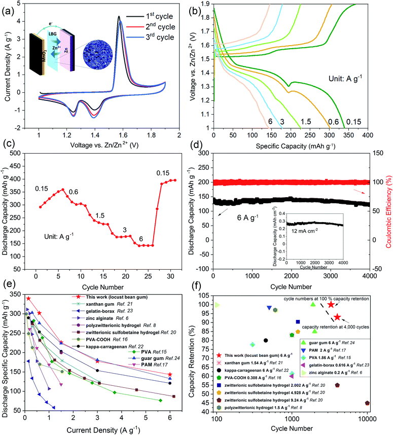 | ||
| Fig. 4 (a) CV curves for 3 cycles at 0.5 mV s−1 of the ZIBs with the LBG electrolyte. The inset of (a) shows the schematic illustration of the structure of quasi-solid-state ZIBs with the LBG electrolyte. (b) The charging/discharging profiles of the ZIBs with the LBG electrolyte at different current density. (c) Rate performance of the ZIBs with the LBG electrolyte. (d) Cycling performance based on mass of the ZIBs with the LBG electrolyte at 6.0 A g−1. The inset of (d) shows cycling performance based on area of the ZIBs with the LBG electrolyte at 12 mA cm−2. (e) Rate performance (stable capacity) of the ZIBs with the LBG electrolyte compared to recent reports on solid-state Zn–MnO2 batteries.6,8,15–17,20–24 (f) Cycling performance of ZIBs with the LBG electrolyte compared to recent reports on solid-state Zn–MnO2 batteries.6,8,15–17,20–24 | ||
The charge and discharge profiles of the ZIBs with LBG electrolyte at different current densities are shown in Fig. 4b. At 0.15 and 0.6 A g−1, the batteries present two discharge plateaus, which are attributed to consequent H+ and Zn2+ insertion process.39 Interestingly, with the increase in current densities, the discharge platform below 1.3 V gradually becomes invisible, and its contribution to the total capacity decreases significantly, implying that the electrode reaction kinetics in this low discharge plateau region is not as good as that in the upper voltage region.
The rate performances of ZIBs with LBG electrolytes are illustrated in Fig. 4c. During the initial cycles (0.15 A g−1), the capacity increased along with cycling due to the gradual activation of the MnO2 electrode.40 The ZIBs assembled with LBG electrolyte delivered capacities of 339.4, 301.8, 226.1, 177.6 and 143.3 mA h g−1 at 0.15, 0.6, 1.5, 3 and 6 A g−1, respectively. Note that these values were calculated based on MnO2 weight. Although the specific capacity (339.4 mA h g−1) at 0.15 A g−1 is higher than theoretical capacity of MnO2 based on one electron (308 mA h g−1), it was still within the theoretical capacity of MnO2 cathodes based on two electrons (617 mA h g−1).41 The discharge capacity of ZIBs with LBG electrolyte at low densities were gathered and compared to related ref. 42–44 in Fig. S11 (ESI†). Additionally, the batteries exhibited excellent cycling performances with high coulombic efficiency of ∼100%, as well as capacity retention of ∼100% over 3300 cycles (Fig. 4d (based on mass), inset of Fig. 4d (based on area)). The batteries also presented ∼93% capacity retention after 4000 cycles. Note that the areal capacity could be further improved by increasing the quality of the active material per unit area.
The rate performances and cycling capabilities of different solid-state electrolytes of ZIBs are given in Fig. 4e and f. Compared to previously reported solid-state electrolytes for ZIBs based MnO2 cathodes, the ZIBs with LBG electrolyte showed the highest specific capacity at different current densities (Fig. 4e). This was attributed to the elevated ionic conductivity of LBG electrolyte, as well as the good conductivity of rGO in MnO2 cathode.39 Moreover, the cycling performances of ZIBs assembled with LBG electrolyte showed also the highest capacity retention after 4000 cycles when compared to previously reported solid-state electrolytes of ZIBs based MnO2 cathodes (Fig. 4f). The excellent cycling performances originated from the long-term stability of LBG electrolyte in Zn anode. The 1st, 3000th, and 4000th charge and discharge profiles of the ZIBs with LBG electrolyte at 6 A g−1 are shown in Fig. S12 (ESI†). The SEM image of LBG electrolyte after 100 charging/discharging cycles are presented in Fig. S13 (ESI†). After 100 charging/discharging cycles, the LBG electrolyte showed interconnected porous structures, which was similar to pristine LBG electrolyte before cycling. This indicates the good stability of the LBG electrolyte during charging and discharging process.
The energy and power densities of ZIBs assembled with LBG electrolyte are shown in Fig. S14 (ESI†). Note that these values were obtained based on MnO2 weight. The maximum energy density reached 468.34 W h kg−1, and the peak power density was 7.86 kW kg−1.
The electrochemical performances of ZIBs assembled with LBG electrolyte were also evaluated at different temperatures of 0, 20, and 40 °C. As shown in Fig. 5a, the ZIBs assembled with LBG electrolyte delivered specific capacities of 319.1, 235.6 and 156.6 mA h g−1 at 0.6 A g−1. At increased current density of 6 A g−1, the specific capacities of the batteries at 40, 20 and 0 °C were recorded as 163, 118.4 and 78.3 mA h g−1 respectively. The corresponding charge and discharge profiles of the batteries at 6 A g−1 and temperatures of 40, 20, and 0 °C are gathered in Fig. 5b.
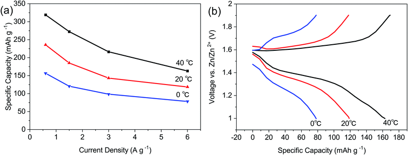 | ||
| Fig. 5 (a) The rate performance of ZIBs with the LBG electrolyte at 0, 20, and 40 °C. (b) Charging and discharging profiles of the ZIBs with the LBG electrolyte at 6 A g−1 at 0, 20, and 40 °C. | ||
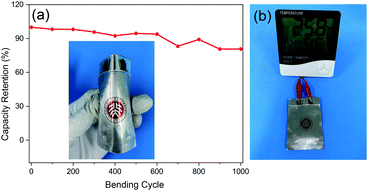
The mechanical flexibility of ZIBs is vital for use in wearable electronic devices. Hence, flexible batteries were assembled with LBG electrolyte. As shown in Fig. 6a, high capacity retention of 80.74% was reached after 1000 bending cycles at bending angle of 90°. Such flexible batteries possessed an open potential of ∼1.44 V, with a thickness as thin as 1.5 mm (Fig. S15, ESI†). Additionally, the resulting batteries successfully powered a thermohygrometer (Fig. 6b). In sum, the high flexibility and good bending performances of these batteries look promising for use in wearable electronic devices.
4. Conclusions
LBG electrolyte was successfully prepared and tested for use in ZIBs for the first time. The as-obtained LBG electrolyte possessed excellent flexibility and high conductivity reaching up 33.57 mS cm−1 at room temperature. The utilization of LBG electrolyte effectively suppressed the formation of zinc dendrites and long-term instability of LBG electrolyte toward Zn anode can be achieved. The ZIBs assembled with LBG electrolyte showed high specific capacity reaching 339.4 mA h g−1 at 0.15 A g−1, fantastic rate performance of 143.3 mA h g−1 at 6 A g−1, and excellent cycling performances with a capacity retention of 100% over 3300 cycles and 93% over 4000 cycles. The batteries also operated in a wide temperature range of 0–40 °C, and retained 80.74% of the capacity after 1000 bending cycles. The excellent electrochemical properties of ZIBs assembled with LBG electrolyte look promising for future practical applications in ZIBs.Author contributions
Binbin Liu: conceptualization, writing – original draft, methodology. Yuan Huang: conceptualization, editing, investigation, funding acquisition. Jiawei Wang: methodology. Zixuan Li: methodology. Guoshen Yang: methodology. Shunyu Jin: investigation. Emad Iranmanesh: editing. Pritesh Hiralal: investigation, funding acquisition. Hang Zhou: conceptualization, editing, investigation, funding acquisition.Conflicts of interest
There are no conflicts to declare.Acknowledgements
This work is supported by Shenzhen Science and Technology Innovation Committee (No. JCYJ20190806145609284, No. GJHZ20190820091203667), Guangdong Basic and Applied Basic Research Foundation (2020A1515010716), the Guangdong Introducing Innovative and Entrepreneurial Teams Program (2019ZT08Z656) and the Fundamental Research Funds for the Central Universities, Sun Yat-sen University. P. Hiralal would like to acknowledge Shenzhen Science and Technology Program (KQTD20190929172522248). Technical support from Tsinghua Shenzhen International Graduate School Materials and Devices Testing Center is gratefully acknowledged.References
- D. L. Chao, C. Zhu, M. Song, P. Liang, X. Zhang, N. H. Tiep, H. F. Zhao, J. Wang, R. M. Wang, H. Zhang and H. J. Fan, Adv. Mater., 2018, 30, 7 Search PubMed.
- Q. Yang, Q. Li, Z. Liu, D. Wang, Y. Guo, X. Li, Y. Tang, H. Li, B. Dong and C. Zhi, Adv. Mater., 2020, 32, 2001854 CrossRef CAS PubMed.
- J. Cong, X. Shen, Z. Wen, X. Wang, L. Peng, J. Zeng and J. Zhao, Energy Storage Mater., 2021, 35, 586–594 CrossRef.
- Y. Cui, Q. Zhao, X. Wu, Z. Wang, R. Qin, Y. Wang, M. Liu, Y. Song, G. Qian, Z. Song, L. Yang and F. Pan, Energy Storage Mater., 2020, 27, 1–8 CrossRef.
- Z. Li, Y. Huang, J. Zhang, S. Jin, S. Zhang and H. Zhou, Nanoscale, 2020, 12, 4150–4158 RSC.
- Y. Tang, C. Liu, H. Zhu, X. Xie, J. Gao, C. Deng, M. Han, S. Liang and J. Zhou, Energy Storage Mater., 2020, 27, 109–116 CrossRef.
- L. Ma, S. Chen, N. Li, Z. Liu, Z. Tang, J. A. Zapien, S. Chen, J. Fan and C. Zhi, Adv. Mater., 2020, 32, 1908121 CrossRef CAS PubMed.
- K. Leng, G. Li, J. Guo, X. Zhang, A. Wang, X. Liu and J. Luo, Adv. Funct. Mater., 2020, 30, 2001317 CrossRef CAS.
- Z. Zhao, J. Zhao, Z. Hu, J. Li, J. Li, Y. Zhang, C. Wang and G. Cui, Energy Environ. Sci., 2019, 12, 1938–1949 RSC.
- J. Wang, Z. Zhao, G. Lu, Y. Zhang, Q. Kong, J. Zhao and G. Cui, Mater. Today Energy, 2021, 20, 100630 CrossRef CAS.
- H. Qiu, X. Du, J. Zhao, Y. Wang, J. Ju, Z. Chen, Z. Hu, D. Yan, X. Zhou and G. Cui, Nat. Commun., 2019, 10, 5374 CrossRef PubMed.
- J. Abdulla, J. Cao, D. Zhang, X. Zhang, C. Sriprachuabwong, S. Kheawhom, P. Wangyao and J. Qin, ACS Appl. Energy Mater., 2021, 4, 4602–4609 CrossRef CAS.
- J. Cao, D. Zhang, C. Gu, X. Wang, S. Wang, X. Zhang, J. Qin and Z.-S. Wu, Adv. Energy Mater., 2021, 2101299 CrossRef.
- J. Cao, D. Zhang, X. Zhang, M. Sawangphruk, J. Qin and R. Liu, J. Mater. Chem. A, 2020, 8, 9331–9344 RSC.
- Y. Zeng, X. Zhang, Y. Meng, M. Yu, J. Yi, Y. Wu, X. Lu and Y. Tong, Adv. Mater., 2017, 29, 1700274 CrossRef PubMed.
- Q. Li, X. Cui and Q. Pan, ACS Appl. Mater. Interfaces, 2019, 11, 38762–38770 CrossRef CAS PubMed.
- H. Li, Z. Liu, G. Liang, Y. Huang, Y. Huang, M. Zhu, Z. Pei, Q. Xue, Z. Tang, Y. Wang, B. Li and C. Zhi, ACS Nano, 2018, 12, 3140–3148 CrossRef CAS PubMed.
- H. Li, C. Han, Y. Huang, Y. Huang, M. Zhu, Z. Pei, Q. Xue, Z. Wang, Z. Liu, Z. Tang, Y. Wang, F. Kang, B. Li and C. Zhi, Energy Environ. Sci., 2018, 11, 941–951 RSC.
- H. Dong, J. Li, S. Zhao, Y. Jiao, J. Chen, Y. Tan, D. J. L. Brett, G. He and I. P. Parkin, ACS Appl. Mater. Interfaces, 2020, 13, 745–754 CrossRef PubMed.
- F. Mo, Z. Chen, G. Liang, D. Wang, Y. Zhao, H. Li, B. Dong and C. Zhi, Adv. Energy Mater., 2020, 10, 2000035 CrossRef CAS.
- S. Zhang, N. Yu, S. Zeng, S. Zhou, M. Chen, J. Di and Q. Li, J. Mater. Chem. A, 2018, 6, 12237–12243 RSC.
- Y. Huang, J. Liu, J. Zhang, S. Jin, Y. Jiang, S. Zhang, Z. Li, C. Zhi, G. Du and H. Zhou, RSC Adv., 2019, 9, 16313–16319 RSC.
- Z. Wang, Z. Ruan, Z. Liu, Y. Wang, Z. Tang, H. Li, M. Zhu, T. F. Hung, J. Liu, Z. Shi and C. Zhi, J. Mater. Chem. A, 2018, 6, 8549–8557 RSC.
- Y. Huang, J. Zhang, J. Liu, Z. Li, S. Jin, Z. Li, S. Zhang and H. Zhou, Mater. Today Energy, 2019, 14, 100349 CrossRef.
- M. Dionísio and A. Grenha, J. Pharm. BioAllied Sci., 2012, 4, 175–185 CrossRef PubMed.
- S. Barak and D. Mudgil, Int. J. Biol. Macromol., 2014, 66, 74–80 CrossRef CAS PubMed.
- B. Ünal, S. Metin and N. D. Işıklı, Int. Dairy J., 2003, 13, 909–916 CrossRef.
- P. Jakóbczyk, M. Bartmański and E. Rudnicka, J. Appl. Electrochem., 2020, 51, 359–371 CrossRef.
- B. Feng, J. Peng, W. Zhang, X. Ning, Y. Guo and W. Zhang, Miner. Eng., 2018, 122, 79–83 CrossRef CAS.
- B. Lee, H. R. Lee, H. Kim, K. Y. Chung, B. W. Cho and S. H. Oh, Chem. Commun., 2015, 51, 9265–9268 RSC.
- S. Fuentes, R. Zarate, R. Espinoza, P. Leyton, D. Diaz-Droguett and V. Fuenzalida, J. Chil. Chem. Soc., 2011, 56, 729–733 CrossRef CAS.
- G. Sen, S. Mishra, U. Jha and S. Pal, Int. J. Biol. Macromol., 2010, 47, 164–170 CrossRef CAS PubMed.
- F. Liu, W. Chang, M. Chen, F. Xu, J. Ma and F. Zhong, Food Hydrocolloids, 2020, 98, 105007 CrossRef CAS.
- S.-N. Yuen, S.-M. Choi, D. L. Phillips and C.-Y. Ma, Food Chem., 2009, 114, 1091–1098 CrossRef CAS.
- N. Bashardoust, J. Josephine, L. Jenita and P. J. D. T. Zakeri-Milani, Dissolution Technol., 2013, 20, 38–43 CrossRef CAS.
- S. Kaity, J. Isaac and A. Ghosh, Carbohydr. Polym., 2013, 94, 456–467 CrossRef CAS PubMed.
- W. Sun, F. Wang, S. Hou, C. Yang, X. Fan, Z. Ma, T. Gao, F. Han, R. Hu, M. Zhu and C. Wang, J. Am. Chem. Soc., 2017, 139, 9775–9778 CrossRef CAS PubMed.
- Y. Huang, J. Mou, W. Liu, X. Wang, L. Dong, F. Kang and C. Xu, Nano-Micro Lett., 2019, 11, 49 CrossRef CAS PubMed.
- Y. Huang, J. Liu, Q. Huang, Z. Zheng, P. Hiralal, F. Zheng, D. Ozgit, S. Su, S. Chen, P.-H. Tan, S. Zhang and H. Zhou, npj Flexible Electron., 2018, 2, 21 CrossRef.
- Y. Huang, Z. Li, S. Jin, S. Zhang, H. Wang, P. Hiralal, G. A. J. Amaratunga and H. Zhou, Carbon, 2020, 167, 431–438 CrossRef CAS.
- G. G. Yadav, J. W. Gallaway, D. E. Turney, M. Nyce, J. Huang, X. Wei and S. Banerjee, Nat. Commun., 2017, 8, 14424 CrossRef PubMed.
- D. Zhang, J. Cao, X. Zhang, N. Insin, S. Wang, J. Han, Y. Zhao, J. Qin and Y. Huang, Adv. Funct. Mater., 2021, 31, 2009412 CrossRef CAS.
- J. Cao, D. Zhang, X. Zhang, S. Wang, J. Han, Y. Zhao, Y. Huang and J. Qin, Appl. Surf. Sci., 2020, 534, 147630 CrossRef CAS.
- J. Cao, D. Zhang, Y. Yue, X. Wang, T. Pakornchote, T. Bovornratanaraks, X. Zhang, Z.-S. Wu and J. Qin, Nano Energy, 2021, 84, 105876 CrossRef CAS.
Footnote |
| † Electronic supplementary information (ESI) available. See DOI: 10.1039/d1ra04294g |
| This journal is © The Royal Society of Chemistry 2021 |

