
 Open Access Article
 This Open Access Article is licensed under a Creative Commons Attribution-Non Commercial 3.0 Unported Licence
Shape-tuned, surface-active and support-free silver oxygen reduction electrocatalyst enabled high performance fully non-PGM alkaline fuel cell†
P. Anandha Ganesh *a,
A. N. Prakrthib,
S. Selva Chandrasekaranc and
D. Jeyakumard
*a,
A. N. Prakrthib,
S. Selva Chandrasekaranc and
D. Jeyakumard
aState Key Laboratory for Mechanical Behavior of Materials, School of Materials Science and Engineering, Xi'an Jiaotong University, No. 28, Xianning West Road, Xi'an, 710049 Shaanxi, China. E-mail: nanoganesh@xjtu.edu.cn
bCentre for Nanoscience and Engineering, Indian Institute of Science, Bangalore-560012, Karnataka, India
cLaboratoire de Simulation Atomistique, INAC, CEA Grenoble, 17, Avenue des Martyrs, 38000 Grenoble, France
dFuel Cell Catalysis and Nano-materials Group, Functional Materials Division, CSIR-Central Electrochemical Research Institute, Karaikudi – 630006, Tamil Nadu, India
First published on 16th July 2021
Abstract
Exploring non-platinum group metal (n-PGM) based efficient oxygen reduction reaction (ORR) electro-catalysts is highly important for realizing advancement in sustainable next generation-alkaline anion exchange membrane fuel cells (AAEMFCs). Herein, we demonstrate a new “hierarchical shape tuning approach” for the synthesis of controlled sized and shaped non-PGM based Ag ORR electro-catalysts with surface active nano-islands. Hierarchical shapes ranging from spherical (S-AgNs), worm-in-sphere, sphere-in-worm and vermiform (worm-like) Ag nanostructures (V-AgNs) were obtained by precisely varying the ratios of capping agent to dual reducing agents in water at ambient conditions. Compared to S-AgNs, V-AgNs revealed a higher mass normalized ORR Tafel activity (0.303 A mgAg−1 at 0.9 V), onset (1.06 V) and half wave (0.78 V) potentials and higher retention of limiting current density (>88%) after 5000 cycles in 0.5 M potassium hydroxide (KOH) solution attributable to their unique worm like morphology with surface active nano-islands and support free-nature enabled better catalyst utilization. In a fully “non-PGM AAEMFC” (n-PAAEMFC), V-AgNs exhibited the highest fuel cell activity of 115.6 mW cm−2 and stable short-term durability (∼240 h) compared to S-AgNs (41.3 mW cm−2) and previously reported fully n-PAAEMFCs indicating their potential use in next-generation alkaline fuel cells.
1 Introduction
Oxygen reduction reaction is one of the most important electrochemical reactions that occurs in alternative energy devices like fuel cells (acidic or alkaline), metal air batteries, redox flow air batteries etc.1 In general, the ORR is kinetically sluggish and requires an efficient electro-catalyst that is durable under operating conditions of clean energy conversion devices like proton exchange membrane fuel cells (PEMFCs).1 In H2/O2 fed PEMFCs, PGMs supported on carbon were used as conventional ORR electro-catalysts.2,3 However, the commercialization of PEMFCs was hampered owing to the expensive and scarce PGMs, carbon corrosion, particle detachment issues etc. under the acidic PEMFC's H+ environment.4–6 On the other hand, H2/O2 fed AAEMFCs afford an OH− environment and the advantage of using relatively cheap non-PGM based electro-catalysts for ORR.7 Further, it was well established that AAEMFCs have the added advantage of reduced fuel cross over from anode to membrane compartment and water flooding issues compared to acidic PEMFCs.8 However, carbonation issues (electrolyte-carbon support effect) and sluggish ORR kinetics (non-PGM catalyst effect) caused by carbon supported catalysts reduce the performance of AAEMFCs.9 For example, commercial Pt based ORR or hydrogen oxidation reaction (HOR) catalysts show moderate activity and durability for AAEMFCs, but their less abundance and high cost hinders their long-term usage for future practical applications.10 Hence, a non-PGM, carbon-free electro-catalyst that exhibits enhanced ORR activity and durability in alkaline medium and minimizes the above mentioned issues is highly essential for sustainable AAEMFCs commercialization. Furthermore, considering the AAEMFCs it is well established that, ORR in alkaline medium undergoes either through the most desirable direct 4e− route to form OH− or indirect 2e− route with hydroperoxyl radical (HO2−) intermediate and subsequently to OH− formation.10 Hence, in the current scenario of improving the AAEMFC's performance, one of the daunting challenges is to execute non-precious metal based ORR electro-catalysts that are highly active, endurable and follow direct 4e− ORR pathway. In the last decades, significant research has been conducted and notable progress was achieved in the development of non-PGM based ORR (acidic and alkaline media) electro-catalysts including transition metal oxides and heteroatom doped carbon materials.11–13 In the recent years, great progress has been attained in exploring M–N–C (M = Fe, Co, Ni, Mn etc.) electro-catalysts where ‘M’ based defects or active sites (such as FeN4 active centers in Fe–N–C) were known to influence the ORR activity along with coexisting N (nitrogen), C (carbon) counterparts.11,14 While most of these non-PGM ORR electro-catalysts exhibit favorable oxygen adsorption free energy, high OH− ion and solvated oxygen coverage in alkaline media, ORR process on these electro-catalysts is highly dominated by ‘outer sphere electron transfer’.9 Furthermore, the very low active density of M–N–C ORR catalysts lower the AAEMFC's performance9 and hence, inevitably include PGM based HOR catalysts at their anode side.8Considering other non-PGM based electro-catalysts, silver was recognized as a relatively less precious, abundant and active ORR electro-catalyst for AAEMFCs.7,15,16 In the last decades, carbon supported mono/bimetallic silver based electro-catalysts10,17 has been used with the aim to harness the meritorious electrochemical properties of Ag such as high ORR activity, stability and more anodic onset potential for Ag/Ag2O formation than other non-precious metals.7,10 Although, carbon supported Ag electro-catalysts showed moderate ORR activity, they exhibited limited durability owing to the carbon support degradation under operating alkaline electrochemical conditions.10 Further, most of the synthesis methods reported for Ag or other non-PGM based ORR electro-catalysts were complex and lack simultaneous control over their morphology and surface active catalytic sites. Meanwhile, researchers focused on the synthesis of Ag electro-catalysts on different stable forms of carbon (carbon nanofibers, multi-walled carbon nanotubes), non-carbon materials to improve their ORR activity in alkaline medium.10,18–21 While these supported Ag electro-catalysts improved the ORR activity to some extent, the persistence of minimal catalyst utilization and carbonation effect further lead to decreased ORR activity and stability under practical conditions.10,22 In order to improve the ORR activity of supported Ag electro-catalysts, researchers focused on wet chemical synthesis of various shaped Ag nanostructured electro-catalysts including nanoplates,23 nanodecahedra,24 nanocubes,24 nanofibers,25 with surface enriched active sites, nano-porosity and oxides using different types of surfactants and reducing agents. In the last decades, shaped Ag nanostructures (nanodisks,26 nanowires,27 nanorods27 etc.) have been synthesized using specific surfactants and templates to study the influence of shape, crystal orientations and surface features on ORR activity.17,28 Nevertheless, due to the complexity in attaining such shaped nanostructures with preferred facets29 and low activity caused by leftover template molecules sticking on nanoparticle surface,30 the shape dependent ORR activity of Ag nanostructures had not yet been fully realized. While support free Ag ORR catalysts with improved activity and durability was recently reported20,31,32 the complex synthetic process for attaining those nanoparticles with controlled size and shape29,30 for reproducible ORR activity inhibit their future applications in AAEMFCs. Hence, support free, shaped silver nanostructures synthesized using a simple strategy (with narrow size distribution) that exhibits durable and efficient ORR activity in alkaline medium is highly preferred.20 It is also important to note that, while there are several reports on PGM-free cathodes or anodes based AEMFC, there are only very few reports on a fully n-PAAEMFC that uses both PGM free cathode and PGM free anode catalysts.8 In the present work, a fully n-PAAEMFC is demonstrated using non-PGM cathode (V-AgNs or S-AgNs) and non-PGM anode (Ni/C) catalysts.
Herein, we report a facile and innocuous “hierarchical shape tuning approach” for the synthesis of support-free V-AgNs with controlled size using various ratios of trisodium citrate as capping agent, sodium borohydride and ascorbic acid as dual reducing agents at ambient temperature. It has been revealed that, the shape of the AgNs can be tuned from spherical to worm like shapes by varying the ratios of capping agent to dual reducing agents. The synthesized nanostructures were characterized using optical spectroscopy, X-ray diffraction (XRD), X-ray photoelectron spectroscopy (XPS), transmission electron microscopy (TEM) and high-resolution transmission electron microscopy (Hr-TEM) studies. Electrochemical characteristics and ORR studies of support-free V-AgNs and S-AgNs electro-catalysts were performed using cyclic voltammetry (CV) and linear sweep voltammetry-rotating ring disk electrode (LSV-RRDE) techniques. The durability of the electro-catalysts was studied using accelerated endurability test (AET) for 5000 continuous potential cycles. The electrochemical results reveal that, support free V-AgNs electro-catalyst exhibit efficient ORR activity and durability in alkaline medium compared to S-AgNs and other shaped Ag electro-catalysts reported so far. The better ORR performance of V-AgNs was ascribed to their narrow size (8–11 nm) distribution, unique worm like morphology and surface active nano-islands enabled high electrochemical active surface area (ECSA) and enhanced catalyst utilization. More importantly, an fully n-PAAEMFC was demonstrated using V-AgNs/S-AgNs ORR catalyst (cathode catalyst layer), Ni/C HOR catalyst (anode catalyst layer), alkaline anion exchange membrane and the results were presented.
2 Experiments
2.1 Synthesis of AgNs electro-catalysts
AgNs were synthesized through a facile wet chemical reduction method33 in water at ambient conditions via a new “hierarchical shape tuning approach”. In the “hierarchical shape tuning approach”, amount of AgNO3 was kept constant throughout the synthetic process and only varying the ratios of capping agent to dual reducing agents. By precisely varying the ratios of capping agent to dual reducing agents, hierarchically tuneable shapes ranging from spherical (S-AgNs), worm-in-sphere, sphere-in-worm and vermiform (worm-like) Ag nanostructures (V-AgNs) were obtained. In a typical synthesis, 8 mmol of AgNO3 was taken in 100 ml of water and continuously stirred for five minutes. To this solution, 0.75 mmol of trisodium citrate decahydrate was added as capping agent and stirred for 10 minutes and the mixture kept undisturbed overnight for aging process. Then, a mixture of dual reducing agents (0.15 mmol of NaBH4 and 0.1 mmol of ascorbic acid) was slowly added to the above solution in drop wise manner under continuous stirring. Likewise, the ratios of capping agent to dual reducing agents amount are precisely varied using same amount of AgNO3 and maintaining other reaction conditions to form hierarchically tuneable shapes (Table S1†). The AgNs suspensions were centrifuged and used for optical spectroscopy and TEM analysis. “Self-settlement approach” (a slightly modified approach of Schmidt et al. strategy34) reported in our recent work35 was used to collect the support-free V-AgNs and S-AgNs electro-catalysts from the nano-suspensions. The nano-suspensions were dried at 60 °C for 7 h and the obtained powder samples were used for XRD, XPS and electrochemical studies.3 Characterization of AgNs electro-catalysts
Optical-surface plasmon resonance (SPR) spectra of AgNs were recorded using an Agilent diode array spectrophotometer (model 8543). XRD patterns of AgNs were recorded using a Bruker X-ray diffractometer (model D8) with Cu K-alpha radiation (λ = 1.5406 Å). XPS analysis of AgNs was employed in a Multilab 2000 (Thermo Fisher Scientific) X-ray photoelectron spectrometer, attached with Mg K-alpha radiation (1253.6 eV) and twin anode X-ray source. The size, shape and morphology of AgNs were studied using TEM/Hr-TEM (FEI Tecnai G2 30 (200 keV) with EDX mapping). CV, LSV-RRDE and AET studies of AgNs electro-catalysts were performed using a bipotentiostat (Biologic, VSM300) equipped with a rotation modulator (Pine Instruments) setup.3.1 Electrochemical characterization of AgNs electro-catalysts
The electrochemical characteristics of V-AgNs and S-AgNs electro-catalysts were analysed using CV and LSV-RRDE techniques in an electrochemical cell containing freshly prepared 0.5 M aqueous KOH electrolyte at ambient conditions. The electrolyte was initially purged with N2 for CV studies or saturated with O2 for ORR studies. RRDE-GC (Pine instruments; geometric glassy carbon disk OD: 5.5 mm and platinum ring OD: 8.5 mm) was used as working electrode for ORR studies. Electrodes are well-polished and cleaned using fine alumina powder (0.05 μm) slurry before each electrochemical measurement. A thin Pt foil was used as counter electrode and mercury/mercurous oxide (MMO, 0.5 M KOH) was used as reference electrode for all electrochemical measurements. For convenience, the potentials are converted to reversible hydrogen electrode (RHE) and accordingly labelled in graphs. LSV-RRDE measurements, collection efficiency (of 0.34) and number of electrons transferred during ORR process were calculated as reported in our previous work36 using 0.5 M KOH electrolyte. The scan rate for CV is 50 mV s−1 and for LSV-RRDE is 5 mV s−1. For ORR studies, the LSV-RRDE was rotated at three different rotation rates per minute (rpm) of 400, 900 and 1600 and a ring potential of 1.3 V vs. RHE was held for all rpm. All the CV and LSV-RRDE calculations were done after background correction to mitigate the contribution of charging/capacitive currents. After CV and LSV-RRDE studies, AET of electro-catalysts was performed in 0.5 M KOH at a scan rate of 0.25 V s−1 under O2 saturated conditions to evaluate their short-term ORR stability for 5000 continuous potential cycles.4 Membrane electrode assembly (MEA)
The catalyst inks were formulated using required amount of the electro-catalysts (Ni/C for anode and V-AgNs or S-AgNs for cathode) with Fumion FAA-3-SOLUT-10 alkaline anion exchange ionomer mixed in ethanol![[thin space (1/6-em)]](https://www.rsc.org/images/entities/char_2009.gif) :isopropyl alcohol mixture (1:1) and sonicated until a stable suspension was obtained. The catalyst ink was brush coated on GDL sheets and dried in vacuum at 60 °C for 7 h. Then, the GDL sheets (anode and cathode) were placed on either side of the FAA-3 anion exchange membranes (with catalyst coated sides facing the membrane) and the MEA (5 cm2 active area) was prepared after hot pressing at 90 °C for 3 min and assembled in a commercial Paxitech™ fuel cell.
:isopropyl alcohol mixture (1:1) and sonicated until a stable suspension was obtained. The catalyst ink was brush coated on GDL sheets and dried in vacuum at 60 °C for 7 h. Then, the GDL sheets (anode and cathode) were placed on either side of the FAA-3 anion exchange membranes (with catalyst coated sides facing the membrane) and the MEA (5 cm2 active area) was prepared after hot pressing at 90 °C for 3 min and assembled in a commercial Paxitech™ fuel cell.
4.1 Fully n-PAAEMFC single cell tests
I–V polarization curves and short-term stability graphs of the fully n-PAAEMFC single cell were obtained by supplying hydrogen (500 sccm) and oxygen (500 sccm) to the anode and cathode respectively at 100% RH. All the fuel cell tests were performed using a multichannel potentiostat (Biologic, VSM300) at an absolute backpressure of 250 kPa and at required operating temperatures such as 30 °C (RT), 40 °C, 50 °C and 60 °C.5 Results and discussions
A new “hierarchical shape tuning approach” coupled with the facile wet chemical reduction method is used for the synthesis of AgNs with hierarchically tunable shapes (Fig. S1 and Table S1†) and their corresponding TEM images are presented in Fig. 1A–D. The TEM image of S-AgNs (Fig. 1A) shows the spherical shaped AgNs in the size range of 7 to 12 nm. Fig. 1B and C show the TEM images of intermediate AgNs growth phase such as worm-in-sphere (higher number of spheres than worm like structures) and sphere-in-worm (higher number of worm like structures than spherical structures). The TEM images of V-AgNs shown in Fig. 1D reveal the dispersion of non-spherical, worm-like silver nanostructures and corroborates with the two optical SPR modes (Fig. 3A). The V-AgNs depict worm like connected structure with blunted heads, numerous curvatures and narrow diameter in the range of 8–11 nm. Further, closer examination (Fig. 1D, inset) of a portion of V-AgNs shows non-smooth and spotty features which could be due to the nano-island like moiety over its surface. The Hr-TEM image of an S-AgNs (Fig. 1E) shows the atomic fringes (planes) with d-spacing values corresponding to Ag. Likewise, the Hr-TEM image of an enlarged portion of V-AgNs (Fig. 1G) shows the edges, kinks and nano-islands like features with relevant d-spacing values. The EDS Ag elemental mapping images of S-AgNs (Fig. 1F) and V-AgNs (Fig. 1H) show the presence and distribution of Ag throughout the structure. The TEM-SAED ring patterns of AgNs (Fig. S2†) show the crystallographic planes and d values corresponding to Ag and correlates with the XRD results (Fig. 3B).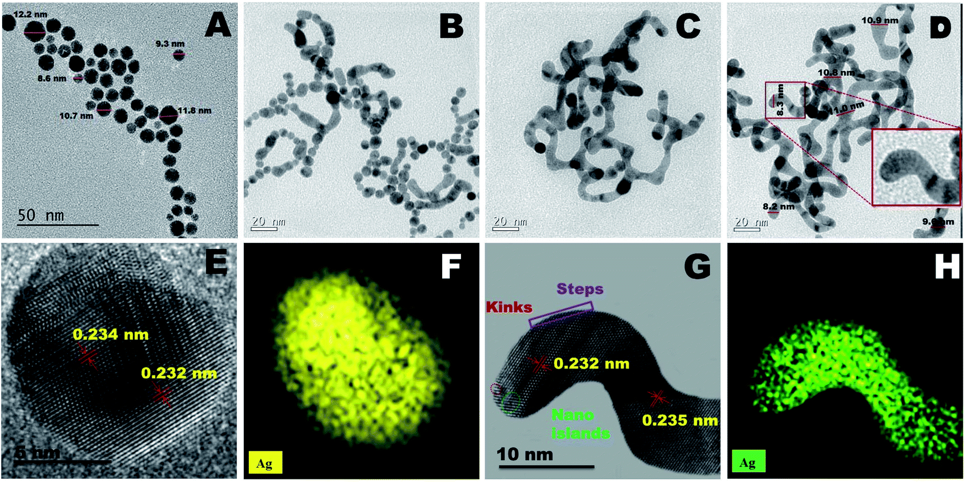 | ||
| Fig. 1 TEM image of hierarchically tuned shapes ranging from Ag nanospheres (A), Ag worm-in-sphere (B), Ag sphere-in-worm (C), Ag nanoworms (D), HRTEM images of a Ag nanosphere (E) and zoomed in part of a Ag nanoworm showing surface islands like feature (G) and their respective EDS elemental mapping images (F and H). | ||
Based on the TEM analysis, the morphology of V-AgNs could be termed as “vermiform” (worm-like) owing to its blunted-heads, spotty, curvy and lengthy bodies resembling the morphological characteristics of a biological worm. In the present case of V-AgNs growth, a facile environment was provided for the silver ions to anisotropically grow into worm like structures based on the knowledge of our previously reported work results.35 In our previous works, it was observed that, the sodium citrate and sodium borohydride concentration can be concomitantly adjusted to form either spherical shaped33 or chain like35 nano-porous morphologies from spherical nano-alloys through galvanic replacement reaction37 at low citrate concentration. Hence, the worm like morphology obtained in the present case, could be due to the “combined aging effect of low citrate concentration and slow addition of dual reducing agents” (sodium borohydride and ascorbic acid). Considering the mechanism of V-AgNs growth, initially the silver ions capped by the low citrate concentration (weak capping) lead to chaining and facile anisotropic growth of silver nuclei. The worm like growth was further stimulated and extended with surface nano-islands formation by the slow addition of dual (sodium borohydride and ascorbic acid) reducing agents as schematically depicted in Fig. 2.
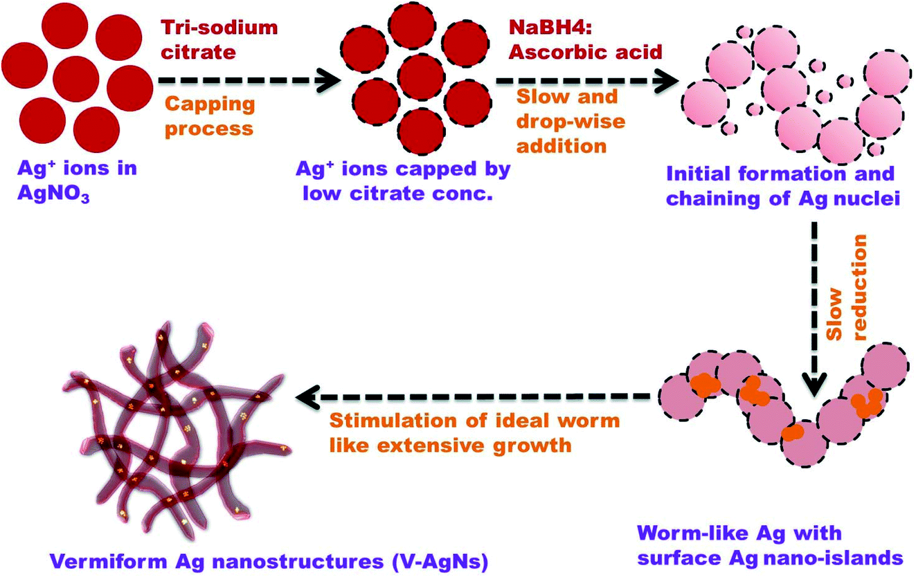 | ||
| Fig. 2 Schematic representation of proposed V-AgNs growth mechanism. | ||
It could be seen from Table S1† that, the silver nitrate concentration was kept constant and the shapes of AgNs can be tuned by precisely varying the ratios of trisodium citrate decahydrate (capping agent) to NaBH4 and ascorbic acid (dual reducing agents). The UV-VIS absorption spectra of AgNs are shown in Fig. 3A. As shown in Table S1,† Ag nanospheres (S-AgNs) were obtained by varying the ratios of trisodium citrate decahydrate (0.3 mmol to 0.75 mmol):NaBH4 (0.525 mmol to 0.15 mmol) and ascorbic acid (0.175 mmol to 0.1 mmol). S-AgNs exhibits a single, symmetrical, high intense SPR peak at around 397 nm (Fig. 3A). It was well established that, Ag nanoparticles (<10 nm sized) with spherical shape would exhibit a single, symmetric, prominent SPR peak at around 400 nm.33 Thus, the SPR characteristics of S-AgNs reveal their sub 10 nm sized spherical shaped particles. While the ratios of trisodium citrate decahydrate (0.25 mmol to 0.5 mmol):NaBH4 (0.4 mmol to 0.3 mmol) and ascorbic acid (0.35 mmol to 0.2 mmol) is varied, few worm like AgNs growth was observed along with spherical shaped AgNs. The SPR spectrum of these Ag (worm-in-sphere) is red shifted compared to S-AgNs and shows a slightly broad peak at around 485 nm (Fig. 3A). Hence, it is clear that, the shift is attributable to the growth of few worms like AgNs in the vicinity of spherical shaped AgNs. It was observed that, worm like AgNs growth is higher than spherical shaped AgNs at the varying ratios of trisodium citrate decahydrate (0.125 mmol to 0.25 mmol):NaBH4 (0.45 mmol to 0.35 mmol) and ascorbic acid (0.425 mmol to 0.4 mmol). For these Ag (sphere-in-worm), a broad visible SPR peak at around 457 nm and a small broad hump at around 727 nm can be seen (Fig. 3A). This kind of SPR characteristics denotes the presence of few spherical AgNs in the neighborhood of worm like AgNs. Likewise, by varying the ratios of trisodium citrate decahydrate (0.05 mmol to 0.15 mmol):NaBH4 (0.5 mmol to 0.435 mmol) and ascorbic acid (0.45 mmol to 0.415 mmol) ideal worm like AgNs growth was observed. SPR feature of these V-AgNs (Ag nanoworms) shows a blue shifted peak at around 418 nm and a visible broad hump at around 726 nm (Fig. 3A). Therefore, it is clear that, this dual intense SPR peaks (owing to the longitudinal and transverse SPR modes) relates to the purely non-spherical i.e. worm like AgNs without any spherical AgNs. In a recent report, photo-chemically prepared silver nano-worms with shorter lengths and irregularly bent shapes exhibited two SPR modes at around 400 and 700 nm.38 Thus, it is pertinent to note that, the non-spherical nature of V-AgNs with increased aspect ratio (length to breadth ratio) tends them to easily polarize longitudinally. As a result, the longitudinal SPR (low energy mode) slightly shifts to higher wavelength and visible at around 726 nm (than that for Ag nanospheres). Furthermore, the blue shifted transverse SPR (high energy mode) seen at around 418 nm could be due to the small breadth of V-AgNs which may facilitate enhanced electro-catalytic ORR activity. Thus, the synthesized four different shapes of AgNs were used to understand the hierarchical growth mechanism from spherical to worm like AgNs and their corresponding TEM and SPR results had been presented. But, considering the random mixing of two different shapes in the cases of Ag (worm-in-sphere) and Ag (sphere-in-worm) further studies are focused w.r.t S-AgNs and V-AgNs only. Thus, among four different kind of structures (S-AgNs, worm-in-sphere, sphere-in-worm and V-AgNs) obtained, S-AgNs and V-AgNs were chosen for further studies owing to their homogeneous morphology (i.e. purely spherical or worm like) rather than mixed shapes as obtained in the remaining two cases. The powder XRD patterns of S-AgNs and V-AgNs samples are recorded and compared with the standard pattern of Ag (JCPDS: 04-0783) as shown in Fig. 3B. The XRD peak positions and crystallographic planes of S-AgNs and V-AgNs are in accordance with the FCC system and standard pattern of Ag. The XRD peaks are broad and the (111) peak exhibits relatively high intensity, showing the nano dimension of AgNs. The average crystallite sizes and lattice constant values of S-AgNs (11.5 nm and 4.082 Å) and V-AgNs (10.6 nm and 4.079 Å) respectively were calculated using Scherrer's equation. Interestingly, the XRD patterns of S-AgNs and V-AgNs show only peaks related to pure Ag but, no peaks corresponding to silver hydroxide or silver peroxide. The lower average crystallite size and lattice constant value of V-AgNs might lead to relatively high surface activity for ORR compared to S-AgNs.
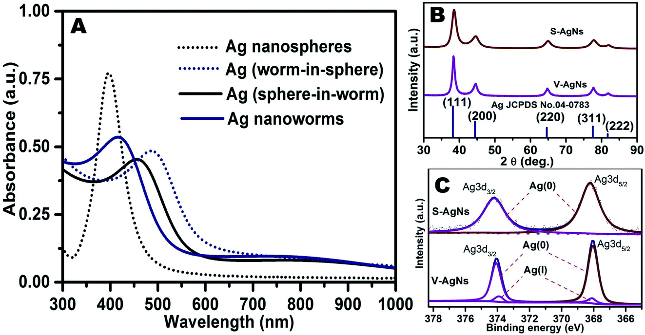 | ||
| Fig. 3 UV-VIS absorbance spectra (A), powder XRD patterns (B) and de-convoluted XPS spectra (C) of AgNs. | ||
The surface features of S-AgNs and V-AgNs electro-catalysts were analyzed using XPS and their respective de-convoluted33 spectra were shown in Fig. 3C. The XPS spectra of S-AgNs shows Ag 3d3/2 and Ag 3d5/2 energy levels at around 374.2 eV and 368.2 eV corresponding to Ag(0) surface states.39 The XPS spectra of V-AgNs show a set of peak for Ag 3d3/2 energy level at around 374.2 eV and 373.9 eV corresponding to Ag(0) and Ag(I) surface states.39 Likewise, another set of peak for Ag 3d5/2 energy level was observed at around 368.2 eV and 367.9 eV related to Ag(0) and Ag(I) surface states.39 Therefore, the XPS results show the presence of Ag(0) surface states and absence of Ag(I) surface states in S-AgNs, whereas for V-AgNs it reveals the presence of both Ag(0) and Ag(I) surface states. It is worthy to note that, the surface atomic composition ratio of Ag(0):Ag(I) states was found to be 98.75:1.25 for V-AgNs i.e. Ag(0) surface states was very high than Ag(I) surface states. This minimal Ag(I) states could be corroborated with the presence of Ag nano-islands like moiety on the surface of V-AgNs (Fig. 1G) which may serve as surface active sites (kinks and steps) for facile oxygen adsorption40 as revealed in our previous reports.35 The presence of surface nano-island like feature in V-AgNs in addition to its unique worm like morphology might promote its surface electro-catalytic activity towards efficient ORR.
The electrochemical activity of support-free V-AgNs and S-AgNs electro-catalysts modified GC were analyzed using CV studies in N2 saturated 0.5 M KOH electrolyte at a scan rate of 50 mV s−1. A stable cyclic voltammogram (Fig. 4A) shows the anodic scan of V-AgNs and S-AgNs electro-catalysts with a forward oxidation peak at around 1.37 V and 1.4 V respectively corresponding to oxidation of surface Ag to Ag2O formation10 and the cathodic scan shows a reverse peak at around 1.07 V and 1.03 V respectively attributable to the reduction of surface Ag2O to Ag.10 It is worthy to note that, V-AgNs and S-AgNs electro-catalysts doesn't shows anodic peaks corresponding to the formation of surface silver hydroxide (AgOH) or silver peroxide species.10 Based on these CV results, the Ag(I) surface states observed in XPS (Fig. 3C) and dark spots visible in Hr-TEM (Fig. 1G) could be attributed to the presence of Ag surface nano-islands33 in V-AgNs electro-catalyst. Further, the Ag2O surface to Ag reduction peak potential of V-AgNs arises more positive with higher current density value than that for S-AgNs. These electrochemical characteristics of V-AgNs electro-catalyst with reasonably tuned shape, size and surface catalytic centers may promote the surface activity of V-AgNs electro-catalyst towards enhanced oxygen adsorption and reduction.
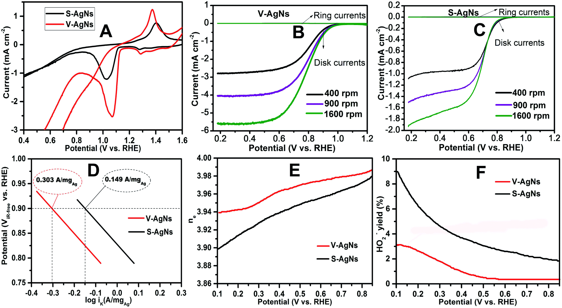 | ||
| Fig. 4 (A) Cyclic voltammogram of AgNs electro-catalysts in N2 saturated 0.5 M KOH, (B and C) LSV-RRDE graphs of AgNs electro-catalysts in O2 saturated 0.5 M KOH, (D) mass corrected Tafel plot of AgNs electro-catalysts, (E and F) plots showing the number of electrons transferred and HO2− yield during ORR process vs. potential. | ||
Following the work of S. Trasatti et al.41 and our previous reports,35,42 ECSA of V-AgNs and S-AgNs electro-catalysts were estimated from their CV reduction peak current area charge (due to the absence of hydrogen adsorption/desorption peak) using the following eqn (1),
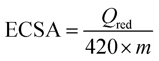 | (1) |
The electrochemical ORR activity of AgNs electro-catalysts were studied using LSV technique in O2 saturated 0.5 M KOH electrolyte at a scan rate of 5 mV s−1. The ORR activity of GC, S-AgNs and V-AgNs were compared (Fig. S3†) to depict the role of AgNs modified and unmodified electrode response towards ORR. The V-AgNs and S-AgNs electro-catalysts modified RRDE-GC was subjected to different rotational speed (400, 900 and 1600 rpm) as shown in Fig. 4B and C respectively. LSV-RRDE graphs show both disk currents and ring currents corresponding to the ORR process and HO2− intermediates formation respectively. It is noteworthy to mention that, ORR limiting current of V-AgNs electro-catalyst (5.56 mA cm−2) at 1600 rpm in O2 saturated 0.5 M KOH is consistent with the theoretical limiting current range of 5–6 mA cm−2 compared to S-AgNs electro-catalyst (2.15 mA cm−2). The steady state linear sweep voltammogram obtained at 1600 rpm was used to determine and compare the ORR activity and related kinetic parameters of AgNs electro-catalysts. The onset potential of V-AgNs and S-AgNs electro-catalysts in the kinetic region was 1.1 V and 0.98 V respectively. In the mixed kinetic-diffusion region, the half wave potentials of V-AgNs and S-AgNs electro-catalysts were 0.78 V and 0.67 V respectively. The ORR mass activity (MA) and specific activity (SA) of V-AgNs and S-AgNs electro-catalysts at 0.9 V were calculated using eqn (2) and (3) respectively.
 | (2) |
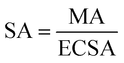 | (3) |
The ORR activity of the AgNs electro-catalysts was further demonstrated using the mass normalized Tafel plots (Fig. 4D) by plotting the iR corrected potential (ViR-free) versus logarithm of mass normalized kinetic current (logiK).
From the Fig. 4D, it could be seen that, the ORR mass normalized Tafel activity (measured as per DOE ORR testing protocol) at 0.9 V of support free V-AgNs (0.303 A mgAg−1) was several times higher than S-AgNs (0.149 A mgAg−1) and Ag nanoplates28 (0.114 A mgAg−1). The Tafel slope values of V-AgNs and S-AgNs electro-catalysts derived from the mass normalized Tafel plots was 57 mV dec−1 and 68 mV dec−1. While Ag catalysts at high loadings was known to exhibit increased ORR activity in alkaline medium,10 the very low catalyst loading of 7 μg cm−2 in the present case doesn't intentionally affect the mass normalized Tafel activity of V-AgNs electro-catalyst owing to its unique morphology and surface nano-islands induced enhanced electro-catalytic ORR activity. It is also envisaged that, the increase ORR mass activity of V-AgNs is due to the worm like structure that confines the mobility of surface Ag atoms. The specific activities of V-AgNs and S-AgNs electro-catalysts at 0.9 V calculated using eqn (3) was 2.95 mA cm−2 and 1.5 mA cm−2 respectively. It is noteworthy that, the specific activity of support free V-AgNs was higher than S-AgNs and recently reported support free Ag nanoplate,28 Ag (110),43 Ag nano-cube,44 and state-of-the-art Ag nanospheres,44 ORR catalysts. Furthermore, V-AgNs and S-AgNs electro-catalysts show increasing disk currents and negligible ring currents for increasing rotational speed in LSV-RRDE studies. Hence, it is envisaged that, both the AgNs electro-catalysts undergo ORR process with negligible/little HO2− intermediates formation. To reveal this, the number of electrons transferred and percentage of HO2− intermediates formed during ORR process need to be estimated using the collection efficiency, disk and ring currents. To start with, average collection efficiency was calculated using potassium ferricyanide system as reported in our previous work36 using the eqn (4),
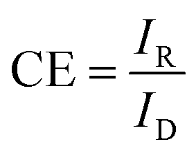 | (4) |
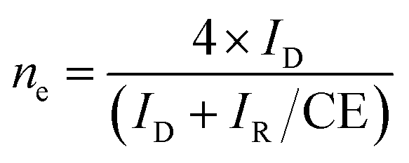 | (5) |
| (i) (O2 + H2O + 2e− → HO2− + OH−), (ii) (H2O + HO2− + 2e− → 3OH−). |
Further, the percentage of HO2− yield formed during ORR at 1600 rpm under LSV-RRDE studies can be estimated from the eqn (6),
 | (6) |
Based on the number of electrons and HO2− yield results, it can also be concluded that, S-AgNs have undergone two electron ORR process. It is noteworthy to mention that, the enhanced ORR activity of V-AgNs could be further elucidated from their favorable XRD crystallographic (reduced average crystallite size and lattice constant value) and XPS (Ag(I) surface chemical states) results compared to S-AgNs.
The short-term ORR stability of V-AgNs and S-AgNs electro-catalysts were studied using AET in LSV-RRDE mode in O2 saturated 0.5 M KOH at ambient conditions. The potential was scanned continuously between 1.2 V and 0.2 V at a scan rate of 0.25 V s−1 for 5000 cycles (i.e. 4 s per cycle) as shown in Fig. 5A and B. From Fig. 5A, it is valuable to note that, about 88% of ORR limiting current density was retained after 5000 potential AET cycles with negligible change in the half wave (2.5 mV shift) and onset potential under accelerated test conditions for V-AgNs electro-catalyst. In contrast, only 85% of ORR limiting current density was retained after 5000 potential AET cycles with prominent change in the half wave (60 mV shift) under accelerated test conditions for S-AgNs electro-catalyst (Fig. 5B). These AET results further depict the enhanced electro-catalytic ORR activity and endurance of V-AgNs owing to their unique worm like morphology and surface active nano-islands. Furthermore, the better short-term stability of support free V-AgNs observed for 5000 potential AET cycles in 0.5 M KOH was higher than that for support free Ag3Sn (2000 cycles in 0.1 M KOH),45 Ag nanoplates (50 cycles in 0.1 M KOH)28 and Ag nano-flower (3000 cycles in 0.5 M KOH)20 ORR catalysts. While, the support free nature of V-AgNs electro-catalyst was supposed to exhibit enhanced mass transport and increased electro-catalyst utilization for ORR, we observed size, morphology and surface active texture enhancement in ORR stability and activity. It is well established that, based on the “volcano plot” (theoretical ORR activities vs. calculated O-binding energy of various transition metals), the ORR activity of Ag increases with decreasing nanoparticle size. Hence, the decreased particle size (∼10 nm) of V-AgNs might cause an increase in binding energy of oxygen per surface catalytic site towards enhanced ORR activity and stability compared to S-AgNs and other shaped Ag ORR electro catalysts. This unique worm like morphology induced enhanced ORR activity and durability of V-AgNs was further confirmed by analyzing the morphological changes of V-AgNs and S-AgNs electro-catalysts before and after AET studies. The electro-catalyst ink used for LSV-ORR studies was re-dispersed in deionized water to form a much diluted dispersion for pre-AET related TEM analysis. Similarly, after 5000 potential cycles, the electro-catalyst material was recovered from the working electrode surface and dispersed in deionized water for post-AET based TEM analysis. The TEM analysis of V-AgNs electro-catalyst shows the retention of its unique worm like morphology before (Fig. S4A†) and negligible size change or no agglomeration even after AET (Fig. S4B†) attributable to their better structural stability and electro-catalytic ORR activity. In contrast, S-AgNs electro-catalyst (Fig. S5A and B†) shows change in the size and shape with agglomerated nanostructures indicating its decreased stability towards ORR. Furthermore, the specific activity at 0.9 V (Fig. 5C) of V-AgNs was higher than S-AgNs and other shaped Ag electro-catalysts in the literature.28,43,44 The reason for the higher ORR performance of V-AgNs compared to S-AgNs is due to their small, narrow particle size distribution, unique worm like morphology providing higher ECSA, low average crystallite size and lattice constant value, Ag(I) surface chemical states (surface nano-islands, kinks and edges) enabled higher percentage of catalytically active sites (under-coordinated surface edge atoms) and the favorable adsorption of the oxygen intermediates at the surface as confirmed by the UV-VIS absorption spectroscopy, XRD, XPS, HRTEM and CV techniques respectively.
 | ||
| Fig. 5 (A and B) AET curves of AgNs electro-catalysts measured at 0.25 V s−1 in 0.5 M KOH. (C) Comparison chart of specific activity values at 0.9 V for AgNs and other shaped Ag electro-catalysts28,43,44 in literature. (D) Fully n-PAAEMFC performance and (E) short-term stability graph between MEAs; anode catalyst layer: commercial NiC, cathode catalyst layer: V-AgNs and S-AgNs. (F) Fully n-PAAEMFC power densities comparison as a function of non-PGM loading in this work and literature reports.46–49 | ||
Based on the above key merits, a fully n-PAAEMFC was fabricated using V-AgNs/S-AgNs cathode catalyst layer, Ni/C anode catalyst layer and alkaline anion exchange membrane. Preliminary I–V studies of this fuel cell using V-AgNs cathode shows a reasonable performance with open circuit voltage of 0.72 V, 0.73 V, 0.75 V and 0.77 V leading to maximum power densities of 56.6 mW cm−2, 75.7 mW cm−2, 94.1 mW cm−2 and 115.6 mW cm−2 at RT (30 °C), 40 °C, 50 °C (Fig. S6†) and 60 °C (Fig. 5D) respectively. Likewise, the fuel cell using S-AgNs cathode exhibits an open circuit voltage of 0.52 V, 0.54 V, 0.57 V and 0.58 V resulting in maximum power densities of 16.5 mW cm−2, 25.4 mW cm−2, 35.3 mW cm−2 and 41.3 mW cm−2 at RT (30 °C), 40 °C, 50 °C (Fig. S7†) and 60 °C (Fig. 5D) respectively. The short term stability test of V-AgNs/S-AgNs cathode based fully n-PAAEMFC was employed by applying a constant current density of 200 mA cm−2 and monitoring the cell voltage fluctuations w.r.t time. The short-term fuel stability of fully n-PAAEMFC at 60 °C (Fig. 5E) of V-AgNs cathode (∼240 h) was higher and shows negligible degradation. In contrast, S-AgNs cathode based fully n-PAAEMFC (Fig. 5E) shows lesser stability (∼136 h). More interestingly, V-AgNs cathode based fully n-PAAEMFC retain its short-term stability after stopping and restarting the cell after 80 h of test duration. In contrast S-AgNs cathode based fully n-PAAEMFC shows a monotonous decrement in its short-term stability after restarting the cell under similar conditions. It is note worthy to mentioned that, short-term stability tests was not carried out for other previous literature reports on fully n-PAAEMFC46–49 (Table S2†) and hence, the short-term stability test results available in the present case would provide valuable information in understanding the stability performance of a fully n-PAAEMFC. To emphasize the advantages of non-PGM mass based fuel fell activity, V-AgNs/S-AgNs cathodes enabled fully n-PAAEMFC activity are presented w.r.t the non-PGM loading mass (mg cm−2) and fairly compared with all the literature results (Fig. 5F and Table S2†). As shown in Fig. 5F, the mass normalized power density (mW per mg non-PGM per cm2) of V-AgNs cathode outperforms S-AgNs and all other Ag or other non-PGM based fully n-PAAEMFC fuel cell46–49 activities reported so far. It is worthy to note that, several AAEMFC have been reported with high fuel cell performance, but involved platinum group metal at either anode or cathode side electro-catalysts. In contrast, the highest fuel cell activity reported in the present case is based on fully n-PAAEMFC which involved purely non-PGM based anode (NiC) and non-PGM based cathode (V-AgNs/S-AgNs) electro-catalysts. Hence, the fuel cell performance in the present work is meaningfully compared only with those of fully n-PAAEMFC reported in literature so far (Fig. 5F and Table S2†). This enhanced fuel cell activity is further ascribed to the support free design of V-AgNs ORR electro-catalyst which helps to mitigate the carbonation issue (at cathode side) owing to its carbon-free environment assisted ORR based performance improvement. It could be observed that, the small size of V-AgNs with surface Ag nano-islands reduced the movement of surface Ag atoms and concomitantly increased the ORR activity compared to S-AgNs and other similar Ag electro-catalysts in literature. The main reason for the higher ORR performance of V-AgNs compared to S-AgNs is elucidated by analyzing the UV-VIS, XRD (small and narrow particle size), XPS, HRTEM (Ag(I) chemical states and Ag surface nano-islands) and CV (higher ECSA) results.
6 Conclusions
A new hierarchical shape tuning approach was employed by precisely varying the ratios of capping agent to dual reducing agents for the facile scalable wet chemical synthesis of four different AgNs at ambient conditions. Compared to S-AgNs and other shaped AgNs in literature, V-AgNs exhibited enhanced ORR activity in terms of high onset potential, half wave potential, mass corrected Tafel activity and specific activity in 0.5 M KOH medium. Further, the accelerated endurability tests performed for 5000 potential cycles showed enhanced stability with negligible change in onset, half wave potentials and high retention of ORR activity for V-AgNs. The efficient and durable electro-catalytic ORR activity of V-AgNs electro-catalyst was attributed to their small and narrow particle size distribution; “unique worm-like shape with surface active nano-islands” in addition to its “support free design” induced better mass transport and enhanced catalyst utilization. Furthermore, to the best of our knowledge, a fully non-PGM based anode and cathode enabled alkaline fuel cell with highest fuel cell activity demonstrated in the present study will provide an essential insight for developing high performing fully n-PAAEMFCs using multifarious non-precious earth abundant materials as ORR electro-catalysts. It is also understood that, the present synthetic strategy not only helps in tuning the shape of AgNs but also greatly helps in promoting the surface activity of unalloyed monometallic silver towards efficient and durable ORR electro-catalysis. In conclusion, worm shaped V-AgNs with highest mass, specific and fuel cell activity compared to other similar reports in the literature could be a viable and cost effective ORR electro-catalyst for numerous applications ranging from the alkaline fuel cells, to metal–air or redox-flow air batteries.Author contributions
P. Anandha Ganesh – conceptualization, data curation, formal analysis, investigation, methodology, validation, visualization, writing – original draft, writing – review & editing. A. N. Prakrthi – validation, visualization, writing – review & editing. S. Selva Chandrasekaran – software, validation, visualization. D. Jeyakumar – funding acquisition, project administration, resources, supervision, validation, visualization, writing – review & editing.Conflicts of interest
Authors declare no conflict of interest.Acknowledgements
The authors thank Director, CSIR-CECRI for the institutional support and DST-INSPIRE grant for the financial support and CSIR-CIF for the central instrumentation facilities used for the present work. Sincere thanks to Prof. Lei Li, MSE, Xian Jiaotong University (XJTU) for his valuable suggestions, Dr Guolong Wang, Ms Xiaowei Shi, Ms Yaling Wang, Mr Zhang Yan, Mr Tang Cheng and all graduates in Prof. Lei Li group for supporting in fuel cell tests, data analysis & interpretation and XJTU – Instrumentation unit for the materials characterization.References
- A. S. Aricò, S. Srinivasan and V. Antonucci, Fuel Cells, 2001, 1, 133–161 CrossRef.
- S. Mukerjee, S. Srinivasan, M. P. Soriaga and J. McBreen, J. Electrochem. Soc., 1995, 142, 1409–1422 CrossRef CAS.
- N. M. Markovic, T. J. Schmidt, V. Stamenkovic and P. N. Ross, Fuel Cells, 2001, 1, 105–116 CrossRef CAS.
- B. Angeliki, S. Shuqin, L. Z. Xing and T. Panagiotis, Catalysts, 2016, 6, 1–22 Search PubMed.
- X. Tuaev, S. Rudi and P. Strasser, Catal. Sci. Technol., 2016, 6, 8276–8288 RSC.
- P. Janthon, F. Viñes, J. Sirijaraensre, J. Limtrakul and F. Illas, Catal. Sci. Technol., 2017, 7, 807–816 RSC.
- J. Guo, A. Hsu, D. Chu and R. Chen, J. Phys. Chem. C, 2010, 114, 4324–4330 CrossRef CAS.
- Z. F. Pan, L. An, T. S. Zhao and Z. K. Tang, Prog. Energy Combust. Sci., 2018, 66, 141–175 CrossRef.
- H. A. Firouzjaie and W. E. Mustain, ACS Catal., 2020, 10, 225–234 CrossRef CAS.
- H. Erikson, A. Sarapuu and K. Tammeveski, ChemElectroChem, 2019, 6, 73–86 CrossRef CAS.
- L. Osmieri, L. Pezzolato and S. Specchia, Curr. Opin. Electrochem., 2018, 9, 240–256 CrossRef CAS.
- S. Kaipannan, P. Anandha Ganesh, K. Manickavasakam, S. Sundaramoorthy, K. Govindarajan, S. Mayavan and S. Marappan, Journal of Energy Storage, 2020, 32, 101774 CrossRef.
- S. S. Balaji, P. Anandha Ganesh, M. Moorthy and M. Sathish, Bull. Mater. Sci., 2020, 43, 151 CrossRef CAS.
- L. Jing, L. Erling, R. Mingbo, S. Ping and X. Weilin, Catalysts, 2015, 5, 1167–1192 CrossRef.
- C. Song and J. Zhang, PEM Fuel Cell Electrocatalysts and Catalyst Layers: Fundamentals and Applications, 2008, pp. 89–129 Search PubMed.
- Q. He and E. J. Cairns, J. Electrochem. Soc., 2015, 162, F1504–F1539 CrossRef CAS.
- J. Ohyama, Y. Okata, N. Watabe, M. Katagiri, A. Nakamura, H. Arikawa, K. Shimizu, T. Takeguchi, W. Ueda and A. Satsuma, J. Power Sources, 2014, 245, 998–1004 CrossRef CAS.
- A. Fazil and R. Chetty, Electroanalysis, 2014, 26, 2380–2387 CrossRef CAS.
- Y. Cheng, W. Li, X. Fan, J. Liu, W. Xu and C. Yan, Electrochim. Acta, 2013, 111, 635–641 CrossRef CAS.
- B. Narayanamoorthy, N. Panneerselvam, C. Sita, S. Pasupathi, S. Balaji and I. S. Moon, J. Electrochem. Soc., 2016, 163, H313–H320 CrossRef CAS.
- S. A. Park, E. K. Lee, H. Song and Y. T. Kim, Sci. Rep., 2015, 5, 1–14 Search PubMed.
- S. Maheswari, P. Sridhar and S. Pitchumani, Electrocatalysis, 2012, 3, 13–21 CrossRef CAS.
- C. L. Lee, H. P. Chiou, C. M. Syu and C. C. Wu, Electrochem. Commun., 2010, 12, 1609–1613 CrossRef CAS.
- Q. Wang, X. Cui, W. Guan, L. Zhang, X. Fan, Z. Shi and W. Zheng, J. Power Sources, 2014, 269, 152–157 CrossRef CAS.
- N. Sharifi, F. Tajabadi and N. Taghavinia, Int. J. Hydrogen Energy, 2010, 35, 3258–3262 CrossRef CAS.
- C. L. Lee, C. M. Syu, C. H. Huang, H. P. Chiou, Y. J. Chao and C. C. Yang, Appl. Catal., B, 2013, 132–133, 229–236 CrossRef CAS.
- N. Kun, C. Liang and L. Gongxuan, Electrochem. Commun., 2008, 10, 1027–1030 CrossRef.
- B. Garlyyev, Y. Liang, F. K. Butt and A. S. Bandarenka, Adv. Sustainable Syst., 2017, 1, 1–7 CAS.
- M. P. Pileni, Nat. Mater., 2003, 2, 145–150 CrossRef CAS PubMed.
- D. Li, C. Wang, D. Tripkovic, S. Sun, N. M. Markovic and V. R. Stamenkovic, ACS Catal., 2012, 2, 1358–1362 CrossRef CAS.
- S. M. Alia, K. Duong, T. Liu, K. Jensen and Y. Yan, ChemSusChem, 2012, 5, 1619–1624 CrossRef CAS PubMed.
- L. Zeng, T. S. Zhao and L. An, J. Mater. Chem. A, 2015, 3, 1410–1416 RSC.
- P. Anandha Ganesh and D. Jeyakumar, Nanoscale, 2014, 6, 13012–13021 RSC.
- W. Liu, A. K. Herrmann, N. C. Bigall, P. Rodriguez, D. Wen, M. Oezaslan, T. J. Schmidt, N. Gaponik and A. Eychmüller, Acc. Chem. Res., 2015, 48, 154–162 CrossRef CAS PubMed.
- P. Anandha Ganesh and D. Jeyakumar, Electrochim. Acta, 2018, 262, 306–318 CrossRef CAS.
- P. Anandha Ganesh and D. Jeyakumar, ChemistrySelect, 2017, 2, 7544–7552 CrossRef CAS.
- P. Anandha Ganesh and D. Jeyakumar, J. Adv. Microsc. Res., 2018, 13, 48–53 CrossRef.
- S. Marpu, S. S. Kolailat, D. Korir, B. L. Kamras, R. Chaturvedi, A. Joseph, C. M. Smith, M. C. Palma, J. Shah and M. A. Omary, J. Colloid Interface Sci., 2017, 507, 437–452 CrossRef CAS PubMed.
- A. V. Naumkin, A. Kraut-Vass, S. W. Gaarenstroom and C. J. Powell, NIST Standard Reference Database Number 20, National Institute of Standards and Technology, Gaithersburg, MD, 2000 Search PubMed.
- A. S. Aricò, A. K. Shukla, H. Kim, S. Park, M. Min and V. Antonucci, Appl. Surf. Sci., 2001, 172, 33–40 CrossRef.
- S. Trasatti and O. A. Petrii, J. Electroanal. Chem., 1993, 321, 353–376 Search PubMed.
- P. Anandha Ganesh and D. Jeyakumar, ChemistrySelect, 2017, 2, 3562–3571 CrossRef.
- B. B. Blizanac, P. N. Ross and N. M. Marković, J. Phys. Chem. B, 2006, 110, 4735–4741 CrossRef CAS PubMed.
- T. Van Cleve, E. Gibara and S. Linic, ChemCatChem, 2016, 8, 256–261 CrossRef CAS.
- Q. Wang, F. Chen, Y. Liu, N. Zhang, L. An and R. L. Johnston, ACS Appl. Mater. Interfaces, 2017, 9, 35701–35711 CrossRef CAS PubMed.
- M. Alesker, M. Page, M. Shviro, Y. Paska, G. Gershinsky, D. R. Dekel and D. Zitoun, J. Power Sources, 2016, 304, 332–339 CrossRef CAS.
- S. Gu, W. Sheng, R. Cai, S. M. Alia, S. Song, K. O. Jensen and Y. Yan, Chem. Commun., 2013, 49, 131–133 RSC.
- S. Lu, J. Pan, A. Huang, L. Zhuang and J. Lu, Proc. Natl. Acad. Sci. U. S. A., 2008, 105, 20611–20614 CrossRef CAS.
- Q. Hu, G. Li, J. Pan, L. Tan, J. Lu and L. Zhuang, Int. J. Hydrogen Energy, 2013, 38, 16264–16268 CrossRef CAS.
Footnote |
| † Electronic supplementary information (ESI) available: Methodology, Fig. S1 to S7, Tables S1 and S2. See DOI: 10.1039/d1ra02718b |
| This journal is © The Royal Society of Chemistry 2021 |