 Open Access Article
Lightweight MWCNT/hollow mesoporous carbon/WPU composite material with excellent electromagnetic shielding performance†
Muqun Wanga,
Yuxuan Qin a,
Wei Gao
 *ab and
Shaofeng Lianga
aSchool of Resources, Environment and Materials, Guangxi University, Nanning 530000, Guangxi, China. E-mail: galaxy@gxu.edu.cn
bGuangxi Engineering and Technology Research Center for High Quality Structural Panels from Biomass Wastes, Nanning 530000, Guangxi, China
First published on 18th November 2021
Abstract
With the rapid increase of intelligent communication equipment, electromagnetic pollution is becoming more and more serious, and the research and application of high-performance electromagnetic shielding materials have attracted great attention from the academic and engineering circles. Traditional metal-based electromagnetic shielding materials have high reflection loss, high density, and are difficult to process. Polymer-based materials with carbon materials as fillers have the advantages of flexibility, light weight, corrosion resistance and low processing costs. They have become the most important materials in the field of electromagnetic shielding in recent years. However, the conductivity of conductive polymer materials is not high. Therefore, improving the electromagnetic shielding performance and the proportion of absorption loss under low density conditions have become key issues for polymer-based electromagnetic shielding materials. MWCNT/MCHMs/WPU composites were prepared by a solution mixing method, with 20 wt%, 40 wt%, 60 wt% MWCNTs and 40 wt% MWCNT/10 wt% MCHMs as fillers. By comparing the effects of different MWCNT content and MCHMs on the dielectric properties, electromagnetic shielding properties and mechanical properties of the MWCNT/MCHMs/WPU composites, the relationship between the structure and properties of the composites has been explored. The 0.6 mm WPU/60 wt% MWCNT composite has an electrical conductivity of 95.4 S m−1 and an electromagnetic shielding effectiveness of 40 dB in the X band. Adding 10 wt% MCHMs to the WPU/40 wt% MWCNT composite material can significantly improve the composite. The δ of the material increased from 51.2 S m−1 to 55.4 S m−1, and the SE increased from 30 dB to 33 dB. The research results show that the increase in MWCNT content and MCHMs is beneficial to improving the electrical conductivity and electromagnetic shielding performance of the composite materials.
Introduction
With the development of electronic communication and electronic products,1 the impact of electromagnetic radiation on daily life and human health cannot be ignored.2 The research and development of efficient electromagnetic shielding materials has become an urgent technical challenge.3–6 The importance of electromagnetic shielding is reflected in the high demands of military and commercial applications, especially in the development of next-generation smart devices. Wearable flexible electronic devices require lightweight, flexible, and efficient electromagnetic shielding materials. Traditional electromagnetic shielding materials mainly involve metal shielding but the metal is usually a rigid material with high density, which is easily corroded and shows difficulty in adjusting the shielding effect.7–9 The most important thing to note is that when metal materials are used as shielding materials, the electromagnetic waves are not effectively attenuated but are reflected on the metal surface, which still causes electromagnetic pollution. Conductive polymer composites (CPCs) have the advantages of low density, flexible design, easy molding, corrosion resistance, etc.,10–16 and are expected to become excellent electromagnetic shielding materials.17,18 The conductive fillers of CPCs are mainly divided into metal fillers and carbon-based fillers. However, conductive polymer composites with metal fillers usually possess disadvantages such as the difficulty of dispersing the metal in the polymer and high density.19–22 Therefore, carbon-based fillers are mostly used.23,24 Carbon-based fillers mainly include carbon black (CB),25–27 carbon fiber (CF),28–30 graphite,31–33 graphene,34–36 and carbon nanotubes (CNTs).37,38 Carbon nanotubes (CNTs) are carbon materials with cylindrical or tubular nanostructures containing six-membered carbon rings. Polymer matrix composites containing carbon nanotube fillers usually have excellent electrical conductivity, thermal conductivity, and mechanical properties.39,40 Also, compared with conventional carbon-based fillers, multi-walled carbon nanotubes (MWCNTs) have a high aspect ratio; thus, they have greater advantages in the preparation of electromagnetic shielding materials. Compared with other polymers, water-based polyurethane (WPU) is non-toxic, non-flammable, flexible, easy to process, and easy to prepare, making it one of the ideal materials as a matrix.41–43 MWCNTs modified by functional groups, hollow mesoporous carbon spheres (MCHMs) with excellent electromagnetic wave absorption properties,44 and WPU were prepared into a thin film through solution blending, and MWCNT/MCHMs/WPU composites with excellent electromagnetic shielding properties were obtained. The composite film also exhibits sufficient flexibility and high-efficiency electromagnetic shielding effectiveness (SE) at low thickness.Experimental
Chemicals and materials
Polycaprolactone diol (PCL, Mn = 2000 g mol−1) was purchased by Japan Daicel Corporation. MWCNT, polyethylene glycol (PEG, Mn = 400 g mol−1), 2-hydroxy-2-methylpropiophenone, isophorone diisocyanate (IPDI), hydroxyethyl acrylate (HEA), 2,2-dimethylolpropionic acid (DMPA), triethylamine (TEA), 2,6-di-tert-butyl p-cresol (BTH), 1,4-butanediol (BDO), dibutyltin dilaurate (DBTDL), and 2-hydroxy-1-[4-(2-hydroxyethyl)phenyl]-2-methyl-1-propiophenone (Irgacure 2959) were purchased by Shanghai Aladdin Biochemical Co., Ltd. Acetone (Ac) was purchased from Sinopharm Chemical Reagent Co., Ltd. MCHMs was self-made in the laboratory.Preparation of waterborne polyurethane
In a 500 mL four-necked round bottom flask equipped with a magnetic stirrer, thermometer, nitrogen protection device, and a condensing reflux device, PCLD, DMPA, and IPDI were added in a definite ratio, the temperature was slowly increased to 90 °C, and the reaction was conducted under N2 protection. At the same time, the isocyanate (–NCO) content in the system was measured by di-n-butylamine–hydrochloric acid titration. When the theoretical value was reached, the system temperature was reduced to 40 °C, the calculated amount of BDO was added for chain extension, and a small amount of BHT inhibitor was added to prevent the explosion of the reactants; then, it was slowly heated to 80 °C to react until the –NCO content reached the theoretical value. During the reaction, an appropriate amount of Ac was added dropwise to reduce the viscosity of the system. After cooling the reactant to 40 °C, a calculated amount of HEA and an appropriate amount of Ac was added, and then, the temperature was increased to 60 °C until the –NCO reaction was complete. The reactants were cooled to room temperature, deionized water and a small amount of TEA was added to vigorously shear, stir, and emulsify, and finally, the solvent Ac was removed by distillation under reduced pressure to obtain a uniform and stable ultraviolet (UV) curable waterborne polyurethane with a solid content of about 35% lotion.Preparation of MCHMs
(1) At stage 1, we manufactured colloidal silica spheres by the hard template method. 1 mol TEOS was added into the solution containing 40 mL ethanol, 8 mL deionized water, and 3 mL NH3·H2O. Then, the solution was magnetically stirred for 20 min at the indoor temperature. (2) At stage 2, 0.1 mol formaldehyde and 1.92 mmol resorcinol were added into the previous solution while stirring for 8 h. During this stage, the molar ratio of formaldehyde to resorcinol remained constant. (3) At stage 3, SiO2@SiO2/phenolic resin was centrifuged and washed several times using ethanol and deionized water. Afterward, the sediment was dried in a vacuum oven for 12 h at 60 °C. (4) At stage 4, the compounds were heated for 6 h under an N2 atmosphere at 700 °C. (5) Finally, SiO2@SiO2/carbon was etched by HF (25%) for removing the silica scaffold.Preparation of MWCNT/MCHMs/WPU
A certain amount of the photoinitiator Irgacure 2959, MWCNTs and MCHMs was added to the synthesized UV curable waterborne polyurethane emulsion, which was poured into a mold to prepare a 0.6 mm film, dried in a vacuum oven at 50 °C to constant weight, and then heated at 365 nm UV on a UV curing machine.Characterization
The morphology of the sample was studied by a Hitachi SU800 scanning electron microscope. The acceleration voltage during the test was 5 kV. The conductivity was tested using an ST2558B-F01 digital four-point probe. The N5224A vector network analyzer was used to test the electromagnetic shielding performance of the composite material in the X band (8.2–12.4 GHz), and the sample was cut into a rectangle of 22.86 mm × 10.16 mm × 2 mm for measurement. The DTG-60 thermogravimetric analyzer produced by Shimadzu Corporation was used to conduct thermogravimetric analysis of the composite film to obtain the thermogravimetric curve of the polymer and to determine its thermal stability. The temperature range was 40–600 °C, and the heating rate was 10 °C min−1. The mechanical properties were tested using the ZQ-990A type small tensile testing machine, and the tensile rate was 10 mm min−1.Results and discussion
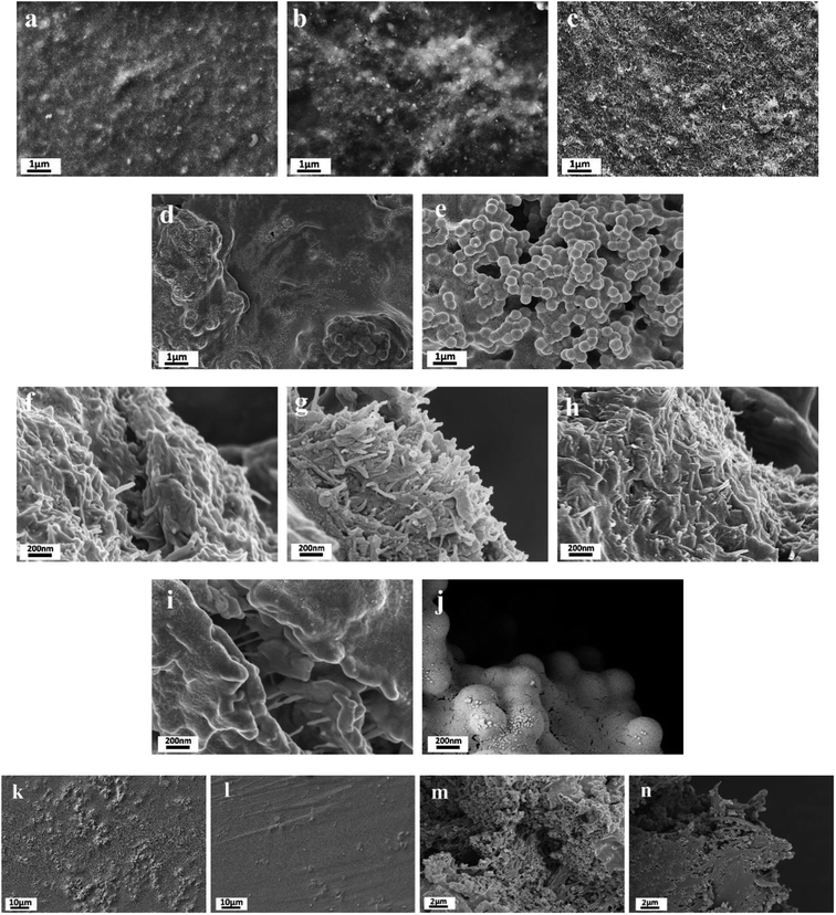
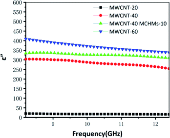
Fig. 1 is the SEM image of MWCNT-20, MWCNT-40, MWCNT-40/MCHMs-10, and MWCNT-60. From the figure, it can be seen that the MWCNTs are uniformly dispersed in the WPU matrix randomly. Because WPU is a water-soluble polymer, MWCNTs can also be uniformly dispersed in water, and the carboxyl groups can react with the –NCO group in WPU to produce stronger crosslinking. From Fig. 1(a)–(c), it can be found that as the content of MWCNTs increases from 20 wt% to 40 wt% and 60 wt%, the number of MWCNTs in the WPU matrix increases. It can be seen from Fig. 1(a) and (e) that some MWCNTs in MWCNT-20 have physical connections but the gaps between the MWCNTs are still relatively large. At this time, the prototype of the conductive network was formed. As the content of MWCNTs increases, the physical connection of MWCNT or multi-walled carbon nanotube bundles becomes tighter, and the gap between MWCNTs in the WPU matrix is also continuously reduced. It can be seen from Fig. 1(c) and (g) that the MWCNT filler in MWCNT-60 is almost saturated, the distance between fillers is small enough, and the conductive network is quite complete. Fig. 1(d) and (h) show the SEM images of WPU doped with 40 wt% MWCNT and 10 wt% MCHMs. It can be seen that the length of the multi-walled carbon nanotubes is about 10–30 μm, and the outer diameter of MCHMs is about 452 nm. Therefore, MWCNTs will overlap with MCHMs.The imaginary part of the dielectric constant (ε′′) of the MWCNT/MCHMs/WPU composite material changes with frequency, as shown in Fig. 2, and ε′′ represents the electrical energy dissipation (dielectric loss). As the frequency increases, ε′′ decreases. The frequency-dependent electrical response can be explained by the existence of electric dipoles. When the frequency of the applied electromagnetic wave increases, the dipoles in the system cannot be fast enough. It can be seen that with the increase in the MWCNT content and the incorporation of MCHMs, the dielectric loss of MWCNT/WPU also shows an increasing trend. Dielectric loss refers to the physical process of transforming a part of the electric energy under the action of an external electric field into heat energy. Dielectric loss generally includes polarization loss and conductance loss. Polarization loss mainly includes dipolar polarization, interface polarization, ion polarization, and electronic polarization. Because ion polarization and electronic polarization general occur in the high-frequency region of 103–106 GHz, it is generally dominated by polarization and interface polarization. Polarization generally occurs between molecules with obvious dipole moments, and interface polarization generally occurs in a structure composed of more than one phase, which is caused by the accumulation and uneven distribution of the space charge of the heterostructure. Therefore, in the MWCNT/MCHMs/WPU composite material, interface polarization and conduction loss are the main factors.45 When the content increases, the local concentration of MWCNTs in the matrix will increase. When the local concentration increases to the permeation threshold, the adjacent conductive fillers are close to each other. When the free charge carrier concentration in the adjacent conductive fillers is high enough, some of the carriers can cross the energy barrier, that is to say, a part of the electrons in the conductive filler can be excited and cross the forbidden band formed between the adjacent conductive fillers to become free electrons, resulting in conductivity. The higher the content of MWCNTs, the more the number of carriers accumulated at the interface, the more electrons that can be excited, the stronger the conductivity, and the higher the dielectric loss. In addition, when the content of MWCNTs is increased from 20 wt% to 40 wt%, the ε′′ increased suddenly from 25 to 300. Due to the high leakage current through the conductive channel formed by the entire system, the dielectric loss suddenly increases when the percolation threshold is exceeded.
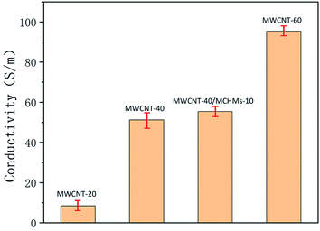
Fig. 3 shows the conductivity of MWCNT-20, MWCNT-40, MWCNT-40/MCHMs-10, and MWCNT-60. According to free electron theory,
 | (1) |
Fig. 3 is the electrical conductivity of the material. It can be known that as ε′′ increases, δ will also increase. When the content of MWCNTs increases from 20 wt% to 40 wt%, δ suddenly increases from 8.4 S m−1 to 51.2 S m−1. With a further increase in the MWCNT content, the conductivity of MWCNT-60 becomes 95.4 S m−1. In a non-conductive matrix polymer, the conductivity is mainly affected by the leakage current generated by the physical connection between the conductive fillers and the adjacent conductive jump current generated by the electronic transition between the fillers. Due to the structural characteristics of MWCNTs and MCHMs, the occurrence of electronic transitions becomes more difficult. Therefore, in MWCNT/MCHMs/WPU composites, the leakage current is the main reason. The increase in the MWCNT content causes an increase in the conductivity. The main reason is that the increase in the conductive filler content causes the conductive fillers to be more likely to be physically connected to form a larger conductive network, and the number of mobile charge carriers in the conductive network increases, which causes an increase in the leakage current. The decrease in the spacing between the external conductive fillers and the increase in the number of carriers will make it easier for the carriers to cross the barrier to form free electrons, resulting in higher hopping current. The increase in the leakage current and hopping current will cause conductivity increase.
In order to have better conductivity even at lower MWCNT content, we investigated the reason why the conductivity of MWCNT-40 increased to 55.4 S m−1 after adding 10 wt% MCHMs.
Fig. 4(a) shows the TEM image of MCHMs; the synthetic process of MCHMs is divided into three steps. First, TEOS is hydrolyzed into silica particles in an alkaline solution. Then, after adding resorcinol and formaldehyde, they polymerize into RF. As the reaction progresses, the remaining silica particles react with RF and condense on the original SiO2 core, forming an SiO2@SiO2/RF core–shell structure. Third, SiO2@SiO2/RF is carbonized at 700 °C to form a solid spherical structure of SiO2@SiO2/C. Finally, MCHMs were obtained by etching SiO2 with HF aqueous solution. MCHMs thus form a hollow mesoporous structure. After adding MWCNTs, MCHMs and MWCNTs are entangled and agglomerated, as shown in Fig. 4(b). Fig. 4(c) is the TEM image of the entanglement of MWCNTs and MCHMs. After adding 10 wt% MCHMs to 40 wt% composite material, because the size of the MCHMs particle is 452 nm, MWCNTs have a higher aspect ratio. On the one hand, MCHMs and MWCNTs contact to make the original dispersion. The MWCNTs are overlapped together to reduce the gap between the conductive fillers, improve the compactness of the conductive network, form electrical contacts more efficiently, and build a saturated conductive network in the MWCNT/MCHMs/WPU composite material. On the other hand, due to an increase in the content of the conductive fillers, the carriers accumulated at the interface of MWCNTs and MCHMs increase. Therefore, the carriers are prone to transition to generate free electrons, which causes an increase in the hopping current and an increase in the conductivity; the principle is shown in Fig. 4(d).
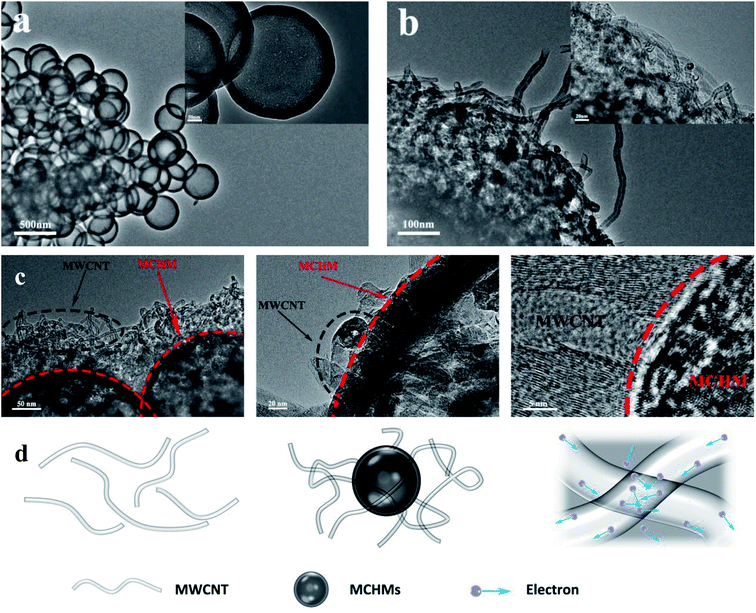 | ||
| Fig. 4 TEM image of MCHMs (a), TEM image of MCHMs and MWCNTs (b), TEM image of the entanglement of MWCNTs and MCHM (c), and schematic diagram of the entanglement of MWCNTs and MCHM (d). | ||
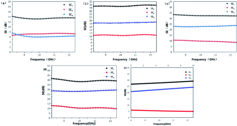
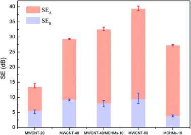
Fig. 5 shows the electromagnetic shielding effectiveness (SET) of MWCNT-20, MWCNT-40, MWCNT-40/MCHMs-10, MWCNT-60, and MCHMs-10 in the X band (8.4–12.4 GHz), wherein SEA stands for absorption loss, which is caused by the impedance mismatch between the shielding material and the space medium, SER stands for reflection loss, and SEM stands for multiple reflection loss, which is usually caused by the inhomogeneity of the internal structure of the shielding material. When SET is greater than 15 dB, SEM is ignored. SET ≥ 20 dB is the effective electromagnetic shielding effectiveness (99% of electromagnetic waves are shielded); SET > 30 dB is the effective electromagnetic shielding effectiveness within the commercial range (99.9% of electromagnetic waves are shielded). The SET of MWCNT-20 is only 14 dB, which cannot effectively shield the electromagnetic waves at this time. However, when the content of MWCNTs increases to 40 wt%, the SET of MWCNT-40 increases to 30 dB, which has reached the requirement of commercial effective electromagnetic shielding. This is because when the MWCNT content is low, the filler content cannot reach the percolation threshold. The MWCNTs are isolated by the poorly conductive WPU matrix, and there is less physical contact between the fillers; thus, a perfect conductive network cannot be formed, and the conductivity is poor. At this time, free electrons can only conduct electricity through the tunnel effect, electromagnetic waves cannot drive the transfer and migration of free electrons, and free charge carriers on the interface cannot undergo transitions. Also, the electromagnetic shielding performance is poor. With the increase in the MWCNT content, on the one hand, because MWCNTs have good conductivity, a perfectly conductive network is formed in the matrix. At this time, there will be a large number of free electrons in the conductive network of the composite material. The free electrons are under the action of electromagnetic waves. Transfer and transition occur along the conductive network, and free electrons will collide during the transfer and transition and cause energy loss. This energy will be converted into heat energy, thus causing an increase in the conductance loss. On the other hand, due to an increase in the conductive fillers, MWCNTs have different polarity and conductivity from the WPU matrix; thus, the charge accumulation and distribution on the interface of MWCNTs and WPU contact is uneven, thereby enhancing the polarization loss on the interface. The increase in conductance loss and polarization loss causes an increase in dielectric loss. Therefore, when electromagnetic waves are incident on the composite material, due to the strong dielectric loss, the electromagnetic waves will be converted into heat energy for loss, and finally, an effective electromagnetic wave shielding effect will be achieved. It can be seen from Fig. 5(e) that even in the MCHMs/WPU material with only 10 wt% MCHMs filled, the SET can reach 28 dB, which can effectively shield the electromagnetic waves at this time, mainly due to the hollow mesoporous structure of MCHMs. After adding 10 wt% MCHMs to MWCNT-40, the SET significantly increased to 33 dB, which reached the effective range of commercial electromagnetic shielding, thus proving that the addition of MCHMs can significantly improve the electromagnetic shielding performance of composite materials.
According to the Schelkunoff electromagnetic shielding theory, when electromagnetic waves propagate to the surface of the shielding material, there are usually three mechanisms of attenuation: (1) absorption loss that enters the shield without being reflected; (2) reflection loss on the incident surface; (3) multiple reflection losses inside the shield, i.e., SET = SEA + SER + SEM; when SE > 15 dB, SEM can be ignored. In order to reduce the secondary electromagnetic wave pollution caused by reflection loss, excellent electromagnetic shielding materials are expected to increase absorption loss and reduce reflection loss; thus, we added MCHMs to increase the absorption loss of electromagnetic shielding materials. Fig. 6 shows the SEA, SER, and SET of MWCNT-20, MWCNT-40, MWCNT-40/MCHMs-10, and MWCNT-60 at 9.04 GHz. It can be seen from Fig. 3 that the SEA > SER and SET < 20 dB for MWCNT-20 because when the filler content is low, the percolation threshold is not reached, and a perfect conductive network cannot be formed in the composite material. Therefore, when electromagnetic waves are incident, most of them are reflected, and a small part of them is incident on the inside of the shield to cause absorption loss. When the MWCNT content increases to 40 wt%, SER > SEA. At this time, the percolation threshold is exceeded, and a perfect conductive network is formed inside the composite material. When electromagnetic waves are incident, a small part is reflected on the surface, and most of them are incident inside the shielding body. Free electrons are excited to produce transfer and transition. In this process, they collide with each other to generate heat energy and thus energy loss. When the MWCNT content is further increased to 60 wt%, the SER and SEA of MWCNT-60 will both increase compared to MWCNT-40. This shows that with the increase in conductive filler, both reflection loss and absorption loss will increase, which will lead to the improvement of electromagnetic shielding performance. However, in order not to cause secondary pollution, we hope to increase the absorption loss without increasing the reflection loss. For MCHMs-10, the SER is as low as 5.6 dB, the SEA is as high as 25.6 dB at 9.05 GHz, and the absorption loss ratio is about 94%, which is conducive for the preparation of electromagnetic shielding composite materials based on absorption loss. Compared with MWCNT-40, the SER of MWCNT-40/MCHMS-10 drops slightly but the SEA increases by 4 dB, thus causing an increase in the SET.
After adding 10 wt% MCHMs to MWCNT-40, SEA increased while SER remained unchanged. We explained the mechanism through the interaction between electromagnetic waves and conductive fillers and the measured electromagnetic shielding performance. The schematic diagram is shown in Fig. 7. (1) The incorporation of MCHMs increases the content of conductive carbon fillers in the matrix. Conductive carbon materials will generate electric dipoles under the action of an external electric field. The higher the concentration of carbon dipoles, the greater the polarization friction and the shielding. The molecules inside the material are more likely to be polarized; thus, the electromagnetic wave can be converted into heat energy through the oscillating friction of the molecular dipole to achieve absorption loss. (2) MCHMs have a high specific surface area, hollow mesoporous structure, and good impedance matching. When electromagnetic waves are incident on MCHMs, most of the electromagnetic waves will be incident into the MCHMs and continue to reflect and scatter in the hollow and mesoporous cavities, thereby causing attenuation and making the incident electromagnetic wave absorb less. (3) The addition of MCHMs bridges a part of the dispersed MWCNTs, makes the conductive network in the composite material more compact, increases the path of free electrons, and causes an increase in the absorption loss. The reason why the SER remains basically unchanged may be that although the interface between the MCHMs and WPU matrix does not match, the filling of MCHMs can improve the impedance matching of the MWCNT/MCHMs/WPU composite material and reduce the reflection of electromagnetic waves on the surface.
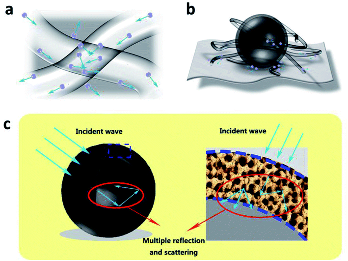 | ||
| Fig. 7 Schematic illustration of electromagnetic shielding mechanisms: (a) conductivity loss, (b) polarization loss and (c) electromagnetic wave attenuation for the MWCNT/MCHMs/WPU composite. | ||
Table 1 lists the electromagnetic shielding performance of other carbon-based/polymer composite materials. Compared with other materials, the composite material obtained in this work can obtain effective electromagnetic shielding performance at low thickness.
| Sample | Filler content (wt%) | Thickness (mm) | SE (dB) | Bandwidth (GHz) | Ref. |
|---|---|---|---|---|---|
| GO/MWCNT-epoxy composite | 15 | 1.0 | 32 | 8.2–12.4 (X-band) | 46 |
| CNT epoxy nanocomposite | 2 | 0.5 | 20/27 | 8.2–12.4 (X-band)/12–18 (Ku-band) | 47 |
| SCF-26/single-wall TUBALL (OCSiAl) CNT | 0.1 | — | 6 | 35 | 48 |
| GNR-Fe3/PVA-PEDOT:PSS | 0.5 | 0.4 | 16.36 | 9.7 | 49 |
| PANI-DBSA-DVB (PDD) | — | 1.0 | 20 | 8.2–12.4 (X-band) | 50 |
| SCF/CB-EMSMPI | 5 + 4 | 0.35 | 23.9 | 8.2–12.4 (X-band) | 51 |
| EP/carbon composites | 7 | 2 | 27.8 | 8.2–12.4 (X-band) | 52 |
| MWCNT-EPDM | 10 | 3 | 28 | 8.2–12.4 (X-band) | 53 |
| PPyFc/MWCNT | 20 | 3 | 23.74 | 2–4 (S-band) | 54 |
| PPyFc/RGO | 21 | 3 | 11.44 | 54 | |
| PPyFc/CB | 22 | 3 | 11.08 | 54 | |
| CB-EMA/EOC | 30 | 2 | 31.4 | 8.2–12.4 (X-band) | 55 |
| MWCNT/MCHMs/WPU | 40 + 10 | 0.6 | 33 | 8.2–12.4 (X-band) | This work |
| MWCNT/WPU | 40 | 0.6 | 30 | 8.2–12.4 (X-band) | This work |
| MWCNT/WPU | 60 | 0.6 | 40 | 8.2–12.4 (X-band) | This work |
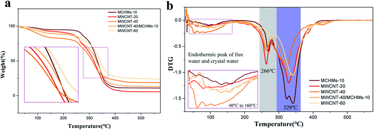
In order to determine the thermal stability of MWCNT/MCHMs/WPU, thermogravimetric tests were performed on WPU, MWCNT-20, MWCNT-40, MWCNT-40/MCHMS-10, and MWCNT-60. They TG and DTG curves of WPU, MWCNT-20, MWCNT-40, MWCNT-40/MCHMS-10, and MWCNT-60 are shown in Fig. 8(a) and (b), respectively.
From the derivative thermogravimetry (DTG) curves in Fig. 8(b), the endothermic peaks of free water and crystal water in WPU materials can be seen in the range of 40 to 160 °C. The main decomposition endothermic peaks of the composite material appear at 266 °C and 329 °C, and the two peaks correspond to the decomposition temperature of the soft and hard segments of the WPU material. We obtained their thermal decomposition temperatures as 330 °C, 329 °C, 307 °C, 306 °C, and 304 °C. It can be seen that with the increase in filler addition, the thermal decomposition temperature slightly decreased, and the endothermic peak intensity was obviously weakened. This is because both MWCNTs and MCHMs have good thermal conductivity, which aggravates the decomposition of WPU. Although the thermal decomposition temperature decreases with the increase in filler addition, it is basically above 300 °C, which proves that the MWCNT/MCHMs/WPU film has good thermal stability. However, it can be seen from the TG curves in Fig. 8(a) that the residual carbon content of MWCNT-20, MWCNT-40, MWCNT-40/MCHMS-10, and MWCNT-60 is not theoretically 20%, 40%, 50%, and 60%, respectively; this is because MWCNTs are carbonylated carbon nanotubes, which are also lost during the thermogravimetric process.
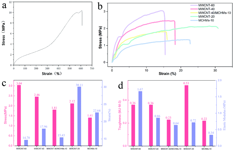
In order to study the effect of the addition of MWCNT/MCHMs on the mechanical properties of MWCNT/MCHMs/WPU composites, tensile tests were performed on MWCNT-20, MWCNT-40, MWCNT-40/MCHMs-10, and MWCNT-60. Fig. 9(b) is the stress–strain curve of MWCNT-20, MWCNT-40, MWCNT-40/MCHMs-10, and MWCNT-60. It can be seen from Fig. 9(a) that the tensile strength and elongation at break of the pure WPU film can reach 10 MPa, 600%. As an elastomer matrix material, the stress–strain curve of WPU shows obvious elastic deformation. The addition of MWCNTs and MCHMs makes the material more prone to plastic deformation, and both the tensile strength and the elongation at break decreased. Since the addition of MWCNTs will affect the degree of microphase separation of the WPU material and prevent the mutual entanglement of the soft and hard segments, the sliding between the WPU molecules during the deformation process was restricted. The maximum elongation of the composite material was compared with that of the WPU material greatly reduced. Under the same deformation state, the fracture strength of the composite material increases with the increase in the amount of MWCNTs. Comparing the stress–strain curves of MWCNT-20, MWCNT-40, and MWCNT-60, we can see that within a certain range, increasing the filler content will increase the tensile strength of the composite material and reduce the elongation at break of the composite material. This is because when a certain amount of MWCNTs is added, it forms a cross-linked network in the matrix. This physically cross-linked network will affect the chain slippage of the polyurethane and cause the density of the physical cross-linking point of the polyurethane matrix to decrease. When the composite material is subjected to a tensile load, stress will be applied at the interface between the MWCNTs and the polyurethane matrix. At this time, the mechanical properties of the pure PU film will decrease. By comparing the stress–strain curves of MWCNT-40 and MWCNT-40/MCHMs-10, it can be known that adding MCHMs will not only lead to a decrease in the tensile strength but also a decrease in the elongation at break. This is mainly because MCHMs with a three-dimensional geometric morphology will inhibit the crystallization of WPU and prevent the movement of the chain segments; thus, the mechanical properties are greatly reduced.
Conclusion
WPU was prepared by the directional synthesis method, and aqueous polyurethane was blended with MWCNT/MCHMs by the solution blending method to prepare composite films with fillers of 20 wt%, 40 wt%, 60 wt% MWCNT and 40 wt% MWCNT + 10 wt% MCHMs; MWCNT can be uniformly dispersed in the matrix, and MWCNTs can be interconnected with MCHMs. For MWCNT/WPU films with different MWCNT contents, with the increase in the MWCNT content, the conductivity of MWCNT-20, MWCNT-40, and MWCNT-60 shows an increasing trend, which was 8.4 S m−1, 51.2 S m−1, and 95.4 S m−1, respectively. When the MWCNT content was 40 wt%, 10 wt% MCHMs was added, and the conductivity increased to 55.4 S m−1. The increase in the MWCNT content and the addition of MCHMs increased the conductivity of the composite material. As the filler content increased, the electromagnetic shielding effectiveness of the composite material also increased, which is positively correlated with the electrical conductivity. The SET of MWCNT-20, MWCNT-40, and MWCNT-60 was 14 dB, 30 dB, and 40 dB, respectively. After adding 10 wt% MCHMs to MWCNT-40, the SET increased to 33 dB. An increase in the MWCNT content improved the electromagnetic shielding performance of the composite material. The addition of MCHMs not only improved the electromagnetic shielding performance but also increased the absorption loss, while the reflection loss remained basically unchanged. MWCNT/MCHMs/WPU composite material has good thermal stability. After adding MWCNTs and MCHMs, the thermal decomposition temperature dropped slightly but was still above 300 °C, showing that it has good thermal stability. The tensile strength of the pure PU film was 10 MPa, and the elongation at break was 600%. After adding MWCNTs and MCHMs, the tensile strength and elongation at break were greatly reduced. However, as the content of MWCNTs increased, the tensile strengths of MWCNT-20, MWCNT-40, and MWCNT-60 showed an upward trend, i.e., 2 MPa, 2.4 MPa, and 3.0 MPa, but the elongation at break decreased, i.e., 30%, 18%, and 15%, respectively. When MCHMs were added, the tensile strength and elongation at break decreased to 1.8 MPa and 16%, respectively. The addition of MWCNTs and MCHMs reduced the mechanical properties of the composite materials.Author contributions
Muqun Wang: conceptualization, data curation, formal analysis, validation, writing-original draft, writing-review & editing. Yuxuan Qin: writing-review & editing, validation. Wei Gao: funding acquisition, resources, supervision. Shaofeng Liang: writing-review & editing, software.Conflicts of interest
There are no conflicts to declare.Notes and references
- H. B. Wang, K. Y. Teng, C. Chen, X. J. Li, Z. W. Xu, L. Chen, H. J. Fu, L. Y. Kuang, M. J. Ma and L. H. Zhao, Mater. Lett., 2017, 186, 78–81 CrossRef CAS.
- G. L. Wang, L. Wang, L. H. Mark, V. Shaayegan, G. Z. Wang, H. P. Li, G. Q. Zhao and C. B. Park, ACS Appl. Mater. Interfaces, 2018, 10, 1195–1203 CrossRef CAS.
- M. S. Cao, X. X. Wang, M. Zhang, J. C. Shu, W. Q. Cao, H. J. Yang, X. Y. Fang and J. Yuan, Adv. Funct. Mater., 2019, 29, 1807398 CrossRef.
- R. Ravindren, S. Mondal, K. Nath and N. C. Das, Composites, Part A, 2019, 118, 75–89 CrossRef CAS.
- S. K. Ghosh, T. K. Das, S. Ghosh, S. Remanan, K. Nath, P. Das and N. C. Das, Compos. Sci. Technol., 2021, 210, 108800 CrossRef CAS.
- S. Ghosh, S. Ganguly, A. Maruthi, S. Jana, S. Remanan, P. Das, T. K. Das, S. K. Ghosh and N. C. Das, Mater. Today Commun., 2020, 24, 100989 CrossRef CAS.
- P. Saini, V. Choudhary, K. N. Sood and S. K. Dhawan, J. Appl. Polym. Sci., 2009, 113, 3146–3155 CrossRef CAS.
- S. N. Tripathi, P. Saini, D. Gupta and V. Choudhary, J. Mater. Sci., 2013, 48, 6223–6232 CrossRef CAS.
- P. Saini, V. Choudhary, B. P. Singh, R. B. Mathur and S. K. Dhawan, Synth. Met., 2011, 161, 1522–1526 CrossRef CAS.
- M. H. Al-Saleh and U. Sundararaj, Macromol. Mater. Eng., 2008, 293, 789 CrossRef CAS.
- V. Kumar, M. A. Muflikhun and T. Yokozeki, Polym. Eng. Sci., 2019, 59, 956–963 CrossRef CAS.
- J. M. Thomassin, C. Jerome, T. Pardoen, C. Bailly, I. Huynen and C. Detrembleur, Mater. Sci. Eng., R, 2013, 74, 211–232 CrossRef.
- J. M. Thomassin, X. Lou, C. Pagnoulle, A. Saib, L. Bednarz, I. Huynen, R. Jerome and C. Detrembleur, J. Phys. Chem. C, 2007, 111, 11186–11192 CrossRef CAS.
- J. M. Thomassin, I. Huynen, R. Jerome and C. Detrembleur, Polymer, 2010, 51, 115–121 CrossRef CAS.
- P. Das, S. Ganguly, S. Banerjee and N. C. Das, Res. Chem. Intermed., 2019, 45, 3823–3853 CrossRef CAS.
- S. Ganji, J. Nanosci. Nanotechnol., 2018, 18, 7623–7640 CrossRef CAS.
- S. Ganguly, S. Ghosh, P. Das, T. K. Das, S. K. Ghosh and N. C. Das, Polym. Bull., 2020, 77, 2923–2943 CrossRef CAS.
- S. Ghosh, S. Ganguly, P. Das, T. K. Das, M. Bose, N. K. Singha, A. K. Das and N. C. Das, Fibers Polym., 2019, 20, 1161–1171 CrossRef CAS.
- Y. Li, B. Shen, X. L. Pei, Y. G. Zhang, D. Yi, W. T. Zhai, L. H. Zhang, X. C. Wei and W. G. Zheng, Carbon, 2016, 100, 375–385 CrossRef CAS.
- M. X. Wan, J. C. Li and S. Z. Li, Polym. Adv. Technol., 2001, 12, 651–657 CrossRef CAS.
- Z. T. Li, M. Q. Ye, A. J. Han and H. Du, J. Mater. Sci.: Mater. Electron., 2016, 27, 1031–1043 CrossRef CAS.
- S. Mondal, S. Ganguly, P. Das, D. Khastgir and N. C. Das, Composites, Part B, 2017, 119, 41–56 CrossRef CAS.
- A. Joshi and S. Datar, Pramana – J. Phys., 2015, 84, 1099–1116 CrossRef CAS.
- C. W. Lou, C. L. Huang, Y. J. Pan, Z. I. Lin, X. M. Song and J. H. Lin, J. Polym. Res., 2016, 23, 1–9 CrossRef CAS.
- S. Geetha, K. K. S. Kumar, C. R. K. Rao, M. Vijayan and D. C. Trivedi, J. Appl. Polym. Sci., 2009, 112, 2073–2086 CrossRef CAS.
- M. E. Spahr, R. Gilardi and D. Bonacchi, in Encyclopedia of Polymers and Composites, ed. S. Palsule, Springer Berlin Heidelberg, Berlin, Heidelberg, 2021, pp. 1–20, DOI:10.1007/978-3-642-37179-0_32-1.
- J. S. Im, J. G. Kim and Y. S. Lee, Carbon, 2009, 47, 2640–2647 CrossRef CAS.
- J. H. Wu and D. D. L. Chung, Carbon, 2002, 40, 445–447 CrossRef CAS.
- Y. Yang, M. C. Gupta and K. L. Dudley, Nanotechnology, 2007, 18 DOI:10.1088/0957-4484/18/34/345701.
- X. H. Huang, B. Dai, Y. Ren, J. Xu and P. Zhu, J. Nanomater., 2015, 2015 Search PubMed.
- X. Luo and D. D. L. Chung, Carbon, 1996, 34, 1293–1294 CrossRef CAS.
- J. P. Gogoi and N. S. Bhattacharyya, J. Appl. Phys., 2014, 116 DOI:10.1063/1.4902860.
- C. Y. Lee, H. G. Song, K. S. Jang, E. J. Oh, A. J. Epstein and J. Joo, Synth. Met., 1999, 102, 1346–1349 CrossRef CAS.
- T. K. Das and S. Prusty, Polym.-Plast. Technol. Eng., 2013, 52, 319–331 CrossRef CAS.
- B. Shen, Y. Li, D. Yi, W. T. Zhai, X. C. Wei and W. G. Zheng, Carbon, 2017, 113, 55–62 CrossRef CAS.
- W. L. Song, M. S. Cao, M. M. Lu, S. Bi, C. Y. Wang, J. Liu, J. Yuan and L. Z. Fan, Carbon, 2014, 66, 67–76 CrossRef CAS.
- A. Sz, A. Xl, A. Ml, A. Jz, A. Se, A. Wy, C. Bzb, B. Xg and Z. B. J. C. Rui, Carbon, 2019, 155, 34–43 CrossRef.
- H. L. Xu, X. W. Yin, Z. C. Li, C. L. Liu, Z. Y. Wang, M. H. Li, L. T. Zhang and L. F. Cheng, Nanotechnology, 2018, 29, 184003 CrossRef PubMed.
- V. N. Popov, Mater. Sci. Eng., R, 2004, 43, 61–102 CrossRef.
- A. Ghasemi, J. Magn. Magn. Mater., 2011, 323, 3133–3137 CrossRef CAS.
- S. T. Hsiao, C. C. M. Ma, H. W. Tien, W. H. Liao, Y. S. Wang, S. M. Li and Y. C. Huang, Carbon, 2013, 60, 57–66 CrossRef CAS.
- Z. H. Zeng, H. Jin, L. P. Zhang, H. Zhang, Z. Chen, F. Gao and Z. Zhang, Carbon, 2015, 84, 327–334 CrossRef CAS.
- J. L. Zhang, D. M. Wu, D. Y. Yang and F. X. Qiu, J. Polym. Environ., 2010, 18, 128–134 CrossRef CAS.
- Y. Qin, M. Wang, W. Gao and S. Liang, RSC Adv., 2021, 11, 14787–14795 RSC.
- Z. H. Zeng, M. J. Chen, H. Jin, W. W. Li, X. Xue, L. C. Zhou, Y. M. Pei, H. Zhang and Z. Zhang, Carbon, 2016, 96, 768–777 CrossRef CAS.
- N. Ucar, B. K. z. Kayap lu, A. n. Bilge, G. Gurel, Q. n. Sencandan and S. Paker, J. Compos. Mater., 2018, 52, 3341–3350 CrossRef CAS.
- L. Mohan, S. Karakkad and S. T. Krishnan, J. Mater. Sci.: Mater. Electron., 2021, 32, 4437–4447 CrossRef CAS.
- M. Y. Yablokov, V. G. Shevchenko, L. A. Mukhortov and A. N. Ozerin, Fullerenes, 2020, 28, 267–271 CAS.
- B. Ray, S. Parmar, K. Date and S. Datar, J. Appl. Polym. Sci., 2020, 138 DOI:10.1002/app.50255.
- S. Das, S. Sharma, T. Yokozeki and S. R. Dhakate, Compos. Struct., 2020, 113293 Search PubMed.
- D. Kong, J. Li, A. Guo and X. Xiao, Chem. Eng. J., 2020, 408, 127365 CrossRef.
- Z. Shen and J. Feng, ACS Sustainable Chem. Eng., 2019, 7, 6 Search PubMed.
- H. Bizhani, A. A. Katbab, E. Lopez-Hernandez, J. M. Miranda and R. Verdejo, Polymers, 2020, 12 DOI:10.3390/polym12102278.
- A. Nazir, H. Yu, L. Wang, Y. He and D. Shen, Appl. Phys. A: Solids Surf., 2020, 126 Search PubMed.
- R. Ravindren, S. Mondal, P. Bhawal, S. Ali and N. C. Das, Polym. Compos., 2019, 40, 1404–1418 CrossRef CAS.
Footnote |
| † Electronic supplementary information (ESI) available. See DOI: 10.1039/d1ra04145b |
| This journal is © The Royal Society of Chemistry 2021 |

