 Open Access Article
Magnetization of graphene oxide nanosheets using nickel magnetic nanoparticles as a novel support for the fabrication of copper as a practical, selective, and reusable nanocatalyst in C–C and C–O coupling reactions†
Parisa Moradia and
Maryam Hajjami *b
*b
aDepartment of Chemistry, Faculty of Science, Ilam University, P. O. Box 69315516, Ilam, Iran
bDepartment of Organic Chemistry, Faculty of Chemistry, Bu-Ali Sina University, 6517838683, Hamedan, Iran. E-mail: mhajjami@yahoo.com; m.hajjami@basu.ac.ir
First published on 27th July 2021
Abstract
Catalyst species are an important class of materials in chemistry, industry, medicine, and biotechnology. Moreover, waste recycling is an important process in green chemistry and is economically efficient. Herein, magnetic graphene oxide was synthesized using nickel magnetic nanoparticles and further applied as a novel support for the fabrication of a copper catalyst. The catalytic activity of supported copper on magnetic graphene oxide (Cu–ninhydrin@GO–Ni MNPs) was investigated as a selective, practical, and reusable nanocatalyst in the synthesis of diaryl ethers and biphenyls. Some of the obtained products were identified by NMR spectroscopy. This nanocatalyst has been characterized by atomic absorption spectroscopy (AAS), scanning electron microscopy (SEM), wavelength dispersive X-ray spectroscopy (WDX), energy-dispersive X-ray spectroscopy (EDS), X-ray diffraction (XRD), thermogravimetric analysis (TGA), Fourier transform infrared spectroscopy (FT-IR), and vibrating sample magnetometer (VSM) techniques. The results obtained from SEM shown that this catalyst has a nanosheet structure. Also, XRD and FT-IR analysis show that the structure of graphene oxide and nickel magnetic nanoparticles is stable during the modification of the nanoparticles and synthesis of the catalyst. The VSM curve of the catalyst shows that this catalyst can be recovered using an external magnet; therefore, it can be reused several times without a significant loss of its catalytic efficiency. The heterogeneity and stability of this nanocatalyst during organic reactions was confirmed by the hot filtration test and AAS technique.
1 Introduction
One of the principles of green chemistry is the use of stable and recyclable catalysts that reduce costs and waste.1–3 Therefore, many efforts have been made recently to introduce these heterogeneous catalysts. For example, the stabilization of metallic nanoparticles on solid materials is an effective way for the synthesis of heterogeneous catalysts.4–6 However, the stabilization of the catalytically active species on heterogeneous substrates leads to a decrease in the catalytic activity.7,8 Therefore, nanostructures with a high surface area are used to revive the catalytic activity of stabilized species.9–11 For example, magnetic nanoparticles,11–13 polymers,14 carbon nanotubes,15 ionic liquids,16,17 mesoporous materials,18–20 graphene oxide,5,21 mineral materials,4,22 metal–organic frameworks (MOFs),23 and biochar nanoparticles24 have been used for the fabrication of metallic catalysts. Among them, graphene oxide nanosheets with a high surface area including high density of carbonyl, hydroxyl, epoxide, and carboxylic acid groups on its surface were used as a support for the stabilization of metallic ions.25 Therefore, graphene oxide can employed as an ideal support for the functionalization and hybridization of other nanomaterials such as metal catalysts for chemical reactions.5 It can also be used as a suitable support for various catalytically active species involving high catalytic activity. However, the recycling of the supported catalyst on the graphene oxide surface is difficult due to its nanosize.26,27 In this context, magnetic nanoparticles have emerged an interesting support in green and sustainable chemistry.28–30 However, magnetic nanoparticles have a high tendency for aggregation due to the high surface energy and attraction of magnetic cores, which lead to a loss of their catalytic activities.5,27 A combination of heterogeneous nanocatalysts with magnetic nanoparticles could be a viable solution for the abovementioned problems.31 These composite systems have a high surface area of the nanocatalysts and simultaneously prevent the aggregation of magnetic cores effectively.31 One of the important composite systems is magnetic graphene oxide, which is composed of graphene oxide and magnetic nanoparticles.32,33 Magnetic graphene oxide has the advantages of both graphene oxide nanosheets (large specific surface area) and magnetic nanomaterials (magnetically recoverable by an external magnet). Therefore, magnetic GO has been reported by the combination of graphene oxide with Fe2O3,34 Fe3O4,35,36 ZnFe2O4,37 CoFe2O4,38 Co,39 and so on. However, magnetic nickel nanoparticles have been rarely used as the magnetic core for the magnetization of GO nanosheets.40It is worthy to note that C–C or C–O coupling reactions are usually performed in the presence of palladium-containing catalysts,18,31 which are very expensive. Meanwhile, Cu-containing catalysts are of interest because of their non-toxicity and cost-effective preparation methods.4 Therefore, herein, we have synthesized magnetic nickel-graphene oxide nanosheets as a support to fabricate the copper catalyst (Cu–ninhydrin@GO–Ni MNPs), and subsequently its catalytic application was studied in the C–C and C–O coupling reactions for the synthesis of diaryl ethers and biphenyls.
2 Experimental
2.1. Synthesis of graphene oxide
Graphene oxide was prepared from graphite powders using modified Hummers' method.21 In this regard, concentrated sulfuric acid (23 mL) was added slowly to a mixture of graphite powder (1 g) and NaNO3 (0.5 g), and it was then stirred in an ice bath for 15 min. Then, potassium permanganate (3 g) was slowly added to the stirred mixture and again allowed to stir for 1.5 h at 0 °C. Then, the mixture was stirred for 2 h at 35 °C. After this, deionized water (46 mL) was slowly added under stirring and the solution temperature was stirred at 98 °C for 30 min. Finally, deionized water (140 mL) and hydrogen peroxide (30%, 10 mL) were added. The resulting solution was washed with HCl (10%) and deionized water. Then, graphite oxide was obtained by centrifugation several times. Finally, GO nanosheets were exfoliated by ultrasound for 30 min.2.2 Synthesis of magnetic nickel nanoparticles (Ni MNPs)
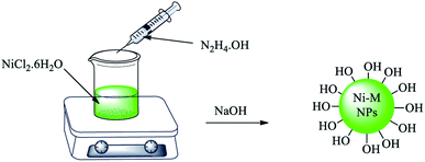
A mixture of NiCl2·6H2O (0.5 g) and ethylene glycol (30 mL) was stirred and heated up to 60 °C. Then, hydrazine hydrate (1.4 mL) was added dropwise. Afterwards, NaOH solution (1 M, 3.6 mL) was added to the mixture, in which a black suspension was formed after 5 min. This suspension was stirred for 1 h at 60 °C. Finally, magnetic nickel nanoparticles (Ni MNPs) were separated with the assistance of an external magnet and washed with deionized water several times. The obtained Ni MNPs were dried at room temperature (Scheme 1).2.3 Synthesis of magnetic graphene oxide using nickel magnetic nanoparticles (GO–Ni MNPs)
Graphene oxide (0.3 g) was dispersed in deionized water (50 mL) for 20 min. Then, Ni MNPs (0.1 g) were added to the mixture and again dispersed for another 20 min. Afterwards, the mixture was stirred for 24 h at room temperature. Finally, GO–Ni MNPs were separated by an external magnet and washed with deionized water. The synthesized GO–Ni MNPs were dried at 50 °C (Scheme 2).2.4 Immobilization of Cu on GO–Ni MNPs for the preparation of Cu–ninhydrin@GO–Ni MNPs
At first, amino-functionalized magnetic GO nanosheets (NH2@GO–Ni MNPs) were prepared according to a recently reported procedure.64 Then, NH2@GO–Ni MNPs (1 g) were dispersed in ethanol (25 mL) for 30 min. Afterwards, 3 mmol of ninhydrin was added to the mixture and refluxed for 24 h under N2 atmosphere. The formed powder (ninhydrin@GO–Ni MNPs) was separated via an external magnet using ethanol washing and dried at 50 °C. Ninhydrin@GO–Ni MNPs (1 g) was dispersed in ethanol (25 mL). Then, Cu(NO3)2·9H2O (2 mmol) was added and refluxed for 24 h under N2 atmosphere. The final product (Cu–ninhydrin@GO–Ni MNPs) was washed with ethanol and obtained via magnetic decantation. The obtained catalyst was dried at 50 °C (Scheme 3).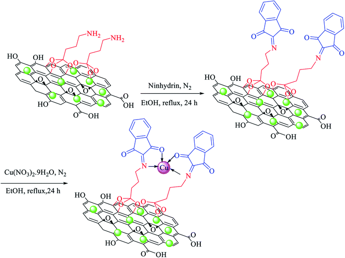 | ||
| Scheme 3 Immobilization of copper on magnetic graphene oxide for the preparation of Cu–ninhydrin@GO–Ni MNPs. | ||
2.5 General procedure for the synthesis of di-aryl ethers
A mixture of phenols (1 mmol), aryl halide (1 mmol), KOH (5 mmol), and Cu–ninhydrin@GO–Ni MNPs (30 mg, 2.12 mol%) in DMSO was stirred at 130 °C and the progress of the reaction was monitored by TLC. At the end of the reaction, the mixture was cooled down and the catalyst was separated by an external magnet and washed with ethyl acetate. The remaining reaction mixture was extracted with H2O and ethyl acetate. The organic phase was dried using anhydrous Na2SO4 (1.5 g) and the organic solvent was evaporated to achieve the pure product.2.6 General procedure for the synthesis of biphenyls
A mixture of aryl halide (1 mmol), Na2CO3 (3 mmol, 0.318 g), 1 mmol of phenylboronic acid (PhB(OH)2), and Cu–ninhydrin@GO–Ni MNPs (30 mg, 2.12 mol%) was stirred in H2O at 80 °C and the progress of the reaction was monitored by TLC. At the end of the reaction, the mixture was cooled down, the catalyst was separated by an external magnet and washed with ethyl acetate. The remaining reaction mixture was extracted with H2O and ethyl acetate. The organic phase was dried using anhydrous Na2SO4 (1.5 g). Then, the organic solvents were evaporated and pure biphenyl derivatives were obtained.2.7 Selected NMR data
3 Results and discussion
3.1 Catalyst characterization
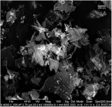
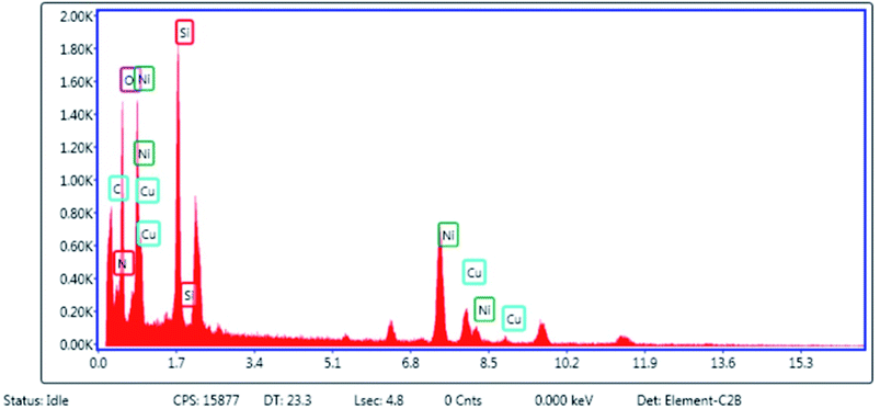
After the preparation of Cu–ninhydrin@GO–Ni MNPs, this catalyst was characterized by SEM, WDX, EDS, FT-IR, TGA, XRD, AAS, and VSM techniques. The SEM image of Cu–ninhydrin@GO–Ni MNPs is shown in Fig. 1. As shown in Fig. 1, this catalyst was synthesized as nanometer sheets with a thickness of less than 10 nm.The elemental composition of Cu–ninhydrin@GO–Ni MNPs was qualitatively determined using EDS analysis (Fig. 2). As expected according to Scheme 3, the obtained results from EDS show that this catalyst is composed of a combination of C, O, Si, N, Ni, and Cu elements.
Also, the obtained results from EDS were confirmed by WDX analysis. The elemental composition distribution of this catalyst was investigated using WDX qualitative analysis. As shown in Fig. 3, all the elements are homogeneously distributed within the structure of this catalyst.
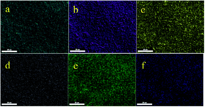 | ||
| Fig. 3 Elemental mapping of (a) carbon, (b) oxygen, (c) silica, (d) nitrogen, (e) nickel, and (f) copper for Cu–ninhydrin@GO–Ni MNPs. | ||
Moreover, the exact amount of copper that was loaded on the modified GO–Ni MNPs was calculated by AAS analysis. According to the obtained results from AAS analysis, there is 0.71 × 10⁻³ mol of copper per gram of Cu–ninhydrin@GO–Ni.
The FT-IR spectra for Ni magnetic nanoparticles (Ni MNPs), graphene oxide nanosheets (GO), magnetic graphene oxide by Ni MNPs (GO–Ni MNPs), and Cu–ninhydrin@GO–Ni MNPs are shown in Fig. 4 and Table 1. The surface of GO is covered by a high density of hydroxyl groups, which appears as a strong band above 3000 cm−1 (Table 1, entry 1) in the FT-IR spectrum.41 The characteristic stretching peak for C–OH groups (Table 1, entry 2) on the surface of GO emerged at 1224 cm−1.42 The bending and stretching vibration of the C–H bonds are present at 878 and 2958 cm−1 in the FT-IR spectra (Table 1, entry 3).24 The bands at 1624 cm−1 and 1714 cm−1 correspond to the vibration of the C![[double bond, length as m-dash]](https://www.rsc.org/images/entities/char_e001.gif) C bonds in the skeletal network of GO (Table 1, entry 4) and C
C bonds in the skeletal network of GO (Table 1, entry 4) and C![[double bond, length as m-dash]](https://www.rsc.org/images/entities/char_e001.gif) O (Table 1, entry 5) bonds, respectively.43,44 The bands at about 462, 800, 1040, and 1082 cm−1 (Table 1, entries 6 and 7) correspond to the vibrations of Si–O–Si and Si–O–C.43 The bands at 1250, 1205, and 1050–1125 cm−1 (Table 1, entries 8–10) are attributed to the vibration of C–O–C, epoxide, and C–O groups attached to GO, respectively.43,45,46 The peak at 1199 cm−1 is attributed to the stretching vibration of the carboxyl C–O bonds.46 The vibration of the C
O (Table 1, entry 5) bonds, respectively.43,44 The bands at about 462, 800, 1040, and 1082 cm−1 (Table 1, entries 6 and 7) correspond to the vibrations of Si–O–Si and Si–O–C.43 The bands at 1250, 1205, and 1050–1125 cm−1 (Table 1, entries 8–10) are attributed to the vibration of C–O–C, epoxide, and C–O groups attached to GO, respectively.43,45,46 The peak at 1199 cm−1 is attributed to the stretching vibration of the carboxyl C–O bonds.46 The vibration of the C![[double bond, length as m-dash]](https://www.rsc.org/images/entities/char_e001.gif) N bonds is present at 1625 cm−147 in the FT-IR spectrum of the catalyst (Table 1, entry 12).
N bonds is present at 1625 cm−147 in the FT-IR spectrum of the catalyst (Table 1, entry 12).
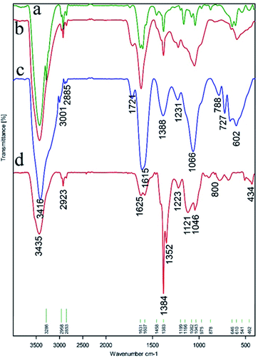 | ||
| Fig. 4 FT-IR spectra of (a) Ni magnetic nanoparticles (Ni MNPs), (b) graphene oxide nanosheets (GO), (c) magnetic graphene oxide by Ni MNPs (GO–Ni MNPs), and (d) Cu–ninhydrin@GO–Ni MNPs. | ||
| Entry | Functional group | Absorption (cm−1) | Reference |
|---|---|---|---|
| 1 | O–H bonds | >3000 | 41 |
| 2 | C–OH bonds | 1224 | 42 |
| 3 | C–H bonds | 878, 2958 | 24 |
| 4 | C![[double bond, length as m-dash]](https://www.rsc.org/images/entities/char_e001.gif) C bonds C bonds |
1624 | 43 |
| 5 | C![[double bond, length as m-dash]](https://www.rsc.org/images/entities/char_e001.gif) O bonds O bonds |
1714 | 44 |
| 6 | Si–O–Si bonds | 462, 800 | 43 |
| 7 | Si–O–C bonds | 1040, 1082 | 43 |
| 8 | C–O–C bonds | 1250 | 45 |
| 9 | Epoxides | 1205 | 43 |
| 10 | Alkoxy C–O bonds | 1050–1125 | 46 |
| 11 | Carboxyl C–O | 1199 | 46 |
| 12 | C![[double bond, length as m-dash]](https://www.rsc.org/images/entities/char_e001.gif) N bonds N bonds |
1625 | 47 |
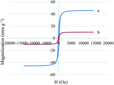
The magnetic properties of Ni MNPs and Cu–ninhydrin@GO–Ni MNPs were studied by a VSM magnetometer at room temperature (Fig. 5). As shown in Fig. 5, Ni MNPs have a good magnetization value of about 45.71 emu g−1. As expected, Cu–ninhydrin@GO–Ni MNPs showed a lower magnetic value than the Ni MNPs, which was found to 10.06 emu g−1. The decrease in the magnetic value of the catalyst compared to that of the Ni MNPs is due to the shielding of the magnetic property by GO and the organic moieties on its surface. The VSM curve of Cu–ninhydrin@GO–Ni MNPs confirmed that this catalyst can be isolated by an external magnet.
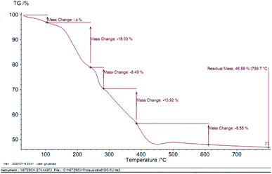
In order to indicate the stabilization of the organic groups on the surface of GO–Ni MNPs, thermogravimetric analysis (TGA) of Cu–ninhydrin@GO–Ni MNPs was performed over air flow and a heating ramp of 10 °C min−1 in the temperature range of 30–800 °C. The TGA curve of Cu–ninhydrin@GO–Ni MNPs is indicated in Fig. 6, which indicates the various mass losses from this catalyst at different temperatures. The first is indicated at low temperatures between 25–100 °C, which corresponds to 4% weight loss. This mass loss is attributed to the evaporation of adsorbed solvents.48,49 The second weight loss, which is about 18%, is observed between 100 and 250 °C, which is attributed to the decomposition of thermally less stable and labile oxygen-containing functional groups (hydroxyl, epoxy, and carboxylic acid).21,50 The third weight loss at about 300 °C corresponds to the more stable oxygen-containing functionalities and the bulk pyrolysis of the carbon skeleton.51,52 The fourth weight loss, which shows a major decrease in the mass of about 31% in the temperature range of 250–450 °C, is attributed to the decomposition of supported organic moieties and the copper complex on the surface if GO–Ni MNPs,21,31 which can be possibly related to the strong chemical interaction between GO–Ni MNPs and the organic groups.
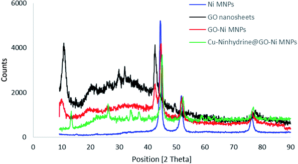
The structure of the synthesized materials was characterized by XRD using a PW1730 instrument from Philips company having CuKα (λ = 1.540598 Å) radiation at 40 kV and 30 mA with 2θ = 9–90°. The normal XRD patterns of Ni MNPs, GO, GO–Ni MNPs, and Cu–ninhydrin@GO–Ni MNPs are shown in Fig. 7. The normal XRD pattern of Ni MNPs reveals three characteristic peaks at 2θ values of 44.55°, 52.25°, and 76.10°, which correspond to the Miller indices (1 1 1), (2 0 0), and (2 2 0), respectively. These reflections confirm a face-centered cubic structure (FCC) of Ni MNPs.53–55 Also, these reflections and peak intensity broadening confirms the formation of Ni nanoparticles.56,57 The strong peaks confirmed that Ni MNPs have a pure and highly crystalline structure.56 The normal XRD pattern of graphene oxide nanosheets reveals characteristic peak at the 2θ value of 10.70° (0 0 2).21 Also, the several weak peaks of 2θ, which are observed at 2θ = 20–30° correspond to the labile oxygen-containing functional groups.58 These less thermally stable oxygen-containing functionalities were observed in the TGA curve as a weight loss between 100 and 250 °C. There are no peaks corresponding to Ni MNPs in the XRD spectrum of GO. The XRD pattern of the GO–Ni MNPs is combined of both diffractions from Ni MNPs and graphene oxide nanosheets, which reveals the successful preparation of GO–Ni MNPs. Also, all the reflections and their positions have remained in the XRD pattern of the Cu–ninhydrin@GO–Ni MNPs after the modification of the nanoparticles and the fabrication of the catalyst, which confirms the crystalline stability of Ni MNPs and graphene oxide nanosheets during the preparation of the catalyst.
3.2 Catalytic application of Cu–ninhydrin@GO–Ni MNPs
After the characterization of Cu–ninhydrin@GO–Ni MNPs, its application was investigated in the Suzuki coupling reaction. The C–C coupling reaction in the presence of Cu–ninhydrin@GO–Ni MNPs is shown in Scheme 4. The optimum conditions were obtained in the cross coupling of phenylboronic acid (PhB(OH)2) with iodobenzene as the model reaction under various parameters and different conditions (Table 2). At first, the amount of the catalyst has been optimized in an aqueous solution of Na2CO3 at 80 °C. For this reason, the model reaction was examined in the absence of the catalyst (Table 2, entry 1), in which no products were obtained even until 6 h. The model reaction was repeated for consecutive runs in the presence of 20, 30, and 40 mg of the catalyst. As shown in Table 2 (entries 2–4), increasing the amount of the catalyst led to an increase in the reaction rate and product yields. However, increasing the amount of the catalyst from 30 mg to 40 mg does not significantly affect the reaction. Therefore, 30 mg (including 2.12 mol% of copper) of Cu–ninhydrin@GO–Ni MNPs has been chosen as the best amount of the catalyst (Table 2, entry 3). Then, the model reaction was examined in different solvents in the presence of a constant amount of the catalyst (30 mg, 2.12 mol%) under the same conditions (Table 2, entries 4–8). Among several solvents such as H2O, DMSO, 1,4-dioxane, DMF, and PEG, the best results were obtained in water as the solvent. Afterwards, the effect of several organic and inorganic bases was studied in the model reaction in the presence of 30 mg of the catalyst in water as the solvent. In these studies, sodium carbonate was showed the best results in term of the reaction time and yield. Finally, the effect of temperature was studied in the model reaction. As shown in Table 2 (entries 3 and 13), decreasing the temperature from 80 to 60 °C led to a reduction in the yield of the products from 97% to 43% for a constant time of the reaction. Based on the abovementioned studies, the optimal conditions for carbon–carbon coupling reaction were obtained in water at 80 °C in the presence of 30 mg (2.12 mol%) of Cu–ninhydrin@GO–Ni MNPs using sodium carbonate (Table 2, entry 3). | ||
| Scheme 4 Carbon–carbon coupling reaction of PhB(OH)2 with aryl halides in the presence of Cu–ninhydrin@GO–Ni MNPs. | ||
| Entry | Amount of catalyst (mg) | Solvent | Base | Temperature (°C) | Time (min) | Yield (%) |
|---|---|---|---|---|---|---|
| 1 | — | H2O | Na2CO3 | 80 | 360 | N.R. |
| 2 | 20 | H2O | Na2CO3 | 80 | 120 | 93 |
| 3 | 30 | H2O | Na2CO3 | 80 | 50 | 97 |
| 4 | 40 | H2O | Na2CO3 | 80 | 40 | 96 |
| 5 | 30 | PEG | Na2CO3 | 80 | 50 | 18 |
| 6 | 30 | DMSO | Na2CO3 | 80 | 50 | 40 |
| 7 | 30 | 1,4-Dioxane | Na2CO3 | 80 | 50 | Trace |
| 8 | 30 | DMF | Na2CO3 | 80 | 50 | 52 |
| 9 | 30 | H2O | KOH | 80 | 50 | 48 |
| 10 | 30 | H2O | NaOCH3 | 80 | 50 | 36 |
| 11 | 30 | H2O | Et3N | 80 | 50 | 58 |
| 12 | 30 | H2O | K2CO3 | 80 | 50 | 79 |
| 13 | 30 | H2O | Na2CO3 | 60 | 50 | 43 |
After obtaining the optimal conditions for the coupling reaction of iodobenzene with PhB(OH)2, the scope of the catalytic activity of Cu–ninhydrin@GO–Ni MNPs was extended to the coupling of other aryl halides with PhB(OH)2. Therefore, various aryl iodides, aryl bromides, and aryl chlorides were investigated in the cross-coupling reaction with PhB(OH)2 in the presence of Cu–ninhydrin@GO–Ni MNPs (Table 3). All the products were isolated in excellent yields and high TOF values in short reaction times. However, the coupling of aryl iodide with PhB(OH)2 is easier and faster than aryl chloride or aryl bromide in the presence of this catalyst. For example, the highest TOF value was obtained for iodobenzene. In the other hand, the lowest TOF value was obtained for chlorobenzene. Therefore, the order of reactivity of aryl halides is aryl iodides > aryl bromides > aryl chlorides. Also, the effect of the electronic nature of the functional groups on the aromatic ring of the aryl halides was investigated by various electron-donating or electron-withdrawing groups. For example, the highest TOF value or a shorter reaction time was obtained for the cross coupling of 4-bromophenol with PhB(OH)2 in the presence of Cu–ninhydrin@GO–Ni MNPs. Meanwhile, the lowest TOF value or a longer reaction time was obtained for the cross coupling of 4-nitrobromobenzene with PhB(OH)2 in the presence of Cu–ninhydrin@GO–Ni MNPs. As shown in Table 3, the reactivity of para-functionalized bromobenzenes can be sorted as 4-OH > H > 4-NO2. Therefore, aryl halides bearing an electron-donating group are faster than aryl halides bearing an electron-withdrawing group in the C–C coupling reaction in the presence of Cu–ninhydrin@GO–Ni MNPs. In order to extend the scope of this procedure, the coupling of a sample of aryl halide containing fused ring compounds with PhB(OH)2 (Table 3, entry 9) was investigated in the presence of Cu–ninhydrin@GO–Ni MNPs, which has a high TOF value and excellent yield of the obtained products were observed in carbon–carbon coupling reactions.
The selectivity of Cu–ninhydrin@GO–Ni MNPs was confirmed for the coupling of 1-bromo-4-chlorobenzene with PhB(OH)2 (Table 3, entry 5). As mentioned, the cross-coupling of aryl bromides is faster than that of aryl chlorides. Therefore, the chloro functional group was not coupled with PhB(OH)2 and pure 4-chloro-1,1′-biphenyl was formed as the only product (Scheme 5).
The catalytic cycle for the cross-coupling reaction of aryl halides with PhB(OH)2 in the presence of Cu–ninhydrin@GO–Ni MNPs is outlined in Scheme 6.31,64 In the first step, oxidative addition gives intermediate I. Then, the reaction of the base with PhB(OH)2 as a Lewis acid produces PhB(OH)3, which, after a transmetallation step, gives intermediate II. Finally, the products were formed after the reduction elimination step and the catalyst was regenerated simultaneously to continue the catalytic cycle. According to this mechanism, non-polar solvents are not capable of solvation of polar intermediates and also the base is insoluble in these solvents. Therefore, non-polar solvents are not suitable for the Suzuki reaction. But the polar solvents have the ability to dissolve the base and can also the dissolve the polar intermediates. Therefore, the polar solvents lead to an increase in the Suzuki reaction rate. Protic solvents provide better conditions for the Suzuki reaction than aprotic solvents. The obtained results in Table 2 show a good agreement with the mechanism of C–C coupling reaction.
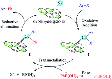 | ||
| Scheme 6 The catalytic cycle for the cross-coupling reaction of aryl halides with PhB(OH)2 in the presence of Cu–ninhydrin@GO–Ni MNPs. | ||
The catalytic activity of Cu–ninhydrin@GO–Ni MNPs was also investigated for the synthesis of di-aryl ethers through the C–O coupling reaction of aryl halides with phenol (Scheme 7). The optimal conditions for the synthesis of ethers were obtained in the coupling reaction of iodobenzene with phenol as the model reaction (Table 4) under different conditions. At first, different amounts of the catalyst were investigated. As shown in Table 4 (entry 1), the model reaction did not occur in the absence of the catalyst even until 6 h. Meanwhile, the reaction rate and product yields were increased with an increase in the amount of the catalyst. Eventually, 30 mg (2.12 mol%) of the catalyst was selected as the optimal amount of Cu–ninhydrin@GO–Ni MNPs (Table 4, entry 2). In the second step, the model reaction was tested in several solvents in the presence of a constant amount of the catalyst (30 mg, 2.12 mol%). Therefore, polar protic solvents (such as PEG and H2O) and polar aprotic solvents (such as DMSO and DMF) were examined in the model reaction. As shown in Table 4, acceptable results were obtained in aprotic solvents. Finally, DMSO was selected as the optimal solvent. In continuation, the effect of the several inorganic and organic bases was examined in the model reaction in DMSO and in the presence of 30 mg of the catalyst. Alkali hydroxides as the base gives better results than other bases in terms of the reaction time and the TOF values. Therefore, potassium hydroxide was selected as the optimal base (Table 4, entry 2). In the final step, the reaction temperature decreased from 130 to 100 °C, whose reaction yield reduced from 98% to 67% within 120 min (Table 4, entry 13). Based on the abovementioned studies, the optimal conditions for the synthesis of ethers were obtained in DMSO as the solvent at 130 °C in the presence of 30 mg (2.12 mol%) of Cu–ninhydrin@GO–Ni MNPs using potassium hydroxide as the base (Table 4, entry 2).
 | ||
| Scheme 7 C–O coupling reaction of phenol with aryl halides in the presence of Cu–ninhydrin@GO–Ni MNPs. | ||
| Entry | Amount of catalyst (mg) | Solvent | Base | Temperature (°C) | Time (min) | Yield (%) |
|---|---|---|---|---|---|---|
| 1 | — | DMSO | KOH | 130 | 300 | N.R. |
| 2 | 30 | DMSO | KOH | 130 | 120 | 98 |
| 3 | 20 | DMSO | KOH | 130 | 160 | 90 |
| 4 | 35 | DMSO | KOH | 130 | 105 | 93 |
| 5 | 30 | PEG | KOH | 130 | 120 | 48 |
| 6 | 30 | DMF | KOH | 130 | 120 | 72 |
| 7 | 30 | H2O | KOH | Reflux | 120 | 35 |
| 8 | 30 | DMSO | Na2CO3 | 130 | 120 | 20 |
| 9 | 30 | DMSO | NaHCO3 | 130 | 120 | 27 |
| 10 | 30 | DMSO | Et3N | 130 | 120 | 55 |
| 11 | 30 | DMSO | NaOCH3 | 130 | 120 | 31 |
| 12 | 30 | DMSO | NaOH | 130 | 120 | 74 |
| 13 | 30 | DMSO | KOH | 100 | 120 | 67 |
The obtained conditions for the coupling reaction of iodobenzene with phenol were extended to the coupling of other aryl halides including aryl iodides, aryl bromides, and aryl chlorides (Table 5). All the products were obtained with high TOF values and good yields in short reaction times. Similar to the Suzuki reaction in the presence of Cu–ninhydrin@GO–Ni MNPs, the reactivity of aryl iodide in the C–O coupling reaction is higher than that of aryl chloride or aryl bromide. As shown in Table 5, it only takes 2 hours for the coupling of iodobenzene with phenol to complete (Table 5, entry 1), while it takes 8 and 12 hours for bromobenzenes and chlorobenzene to complete the reaction, respectively (Table 5, entries 3 and 8). Therefore, the order of reactivity of aryl halides in the synthesis of ethers in the presence of Cu–ninhydrin@GO–Ni MNPs is aryl iodides > aryl bromides > aryl chlorides. Therefore, this catalyst can selectively couple aryl iodides or aryl bromides compared to aryl chlorides (Table 5, entry 7). In order to extend the scope of this procedure, the coupling of 1-bromonaphthalene with phenol (Table 5, entry 9) was examined in the presence of Cu–ninhydrin@GO–Ni MNPs, in which the corresponding ether was obtained in excellent yield.
A cyclic mechanism for the synthesis of diaryl ethers in the presence of Cu–ninhydrin@GO–Ni MNPs is outlined in Scheme 8. The cyclic mechanism includes the oxidative addition, transmetallation, and reduction elimination steps, which lead to the formation of diaryl ethers from the coupling of aryl halides with phenol and the regeneration of the catalyst to continue the catalytic cycle.59
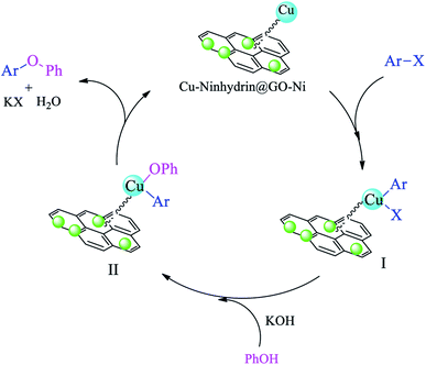 | ||
| Scheme 8 The catalytic cycle for the C–O coupling of aryl halides with phenol in the presence of Cu–ninhydrin@GO–Ni MNPs. | ||
The natural heterogeneity of Cu–ninhydrin@GO–Ni MNPs was studied by the hot filtration test and AAS analysis.60 Initially, the coupling reaction of 4-nitrobromobenzene with PhB(OH)2 in the presence of this catalyst was performed under the optimized conditions. This reaction was stopped after 130 min, in which 61% of 4-nitro-1,1′-biphenyl was obtained as the product at this time. In order to evaluate the copper leaching, the exact amount of copper was calculated in the filtered solution by AAS after removing the catalyst by an external magnet. In this analysis, the concentration of copper in the filtered solution was found to be 0.000003 mol L−1. Therefore, copper leaching is negligible during the reaction. This means that Cu–ninhydrin@GO–Ni MNPs is heterogeneous in nature and the described reactions take place under heterogeneous conditions. To confirm these results, the reaction of 4-nitrobromobenzene with PhB(OH)2 was repeated. Halfway through the completion of the reaction, the reaction stopped and the reaction solution was allowed to proceed in the absence of catalyst. In this stage, 65% of 4-nitro-1,1′-biphenyl was obtained as the product. These experiments confirm that the leaching of copper did not occur. Also, in order to clearly show the catalytic properties, the recycled catalyst in half time of the reaction was reused in the same reaction, in which 90% of the product was obtained after 270 min. Due to the heterogeneous nature of this catalyst, it can be recovered and reused several times. The recoverability of the catalyst is an importance factor for the evaluability of the catalyst applications. Therefore, reusing Cu–ninhydrin@GO–Ni MNPs was examined in the synthesis of both diaryl ethers and biphenyls. In order to investigate this issue, the coupling of 1-bromo-4-chlorobenzene with PhB(OH)2 and also the coupling of iodobenzene with phenol in the presence of Cu–ninhydrin@GO–Ni MNPs were selected as the model reactions. At first, each of the reaction was started under the optimized condition, which can be found in Tables 2 (entry 3) and 4 (entry 2). After the completion of each reaction, the catalyst was recovered by the assistance of an external magnet. Then, to study the reusability of this catalyst, the catalytic activity of the recovered catalyst was evaluated in the next reaction again. The obtained results are summarized in Fig. 8. As shown in Fig. 8, this catalyst can be reused for atleast 8 runs consecutive in C–C or C–O coupling reactions.
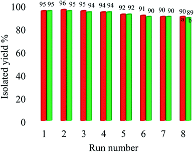 | ||
| Fig. 8 Recyclability of Cu–ninhydrin@GO–Ni MNPs in the coupling of ((a) red line) 1-bromo-4-chlorobenzene with PhB(OH)2 and ((b) green line) iodobenzene with phenol. | ||
In order to show the efficiency of Cu–ninhydrin@GO–Ni MNPs, the obtained results from the coupling of iodobenzene or chlorobenzene with PhB(OH)2 in the presence of this catalyst were compared with the previous methods (Table 6). As shown in Table 5, the products were obtained in higher yield in a shorter time than the other catalysts. Also, palladium catalysts were employed as the catalyst in some of the methods, which is very expensive and more toxic than the copper catalyst. In addition, the Suzuki reaction was carried out in water as the solvent in the presence of Cu–ninhydrin@GO–Ni MNPs; meanwhile, toxic, expensive, and organic solvents were used in other works. Also, the Suzuki reaction was reported in the presence of homogeneous catalysts, which cannot be recovered and reused. On the other hand, Cu–ninhydrin@GO–Ni MNPs can be recovered by an external magnet and recycled for several runs in C–C coupling reactions without a significant loss of its catalytic activity.
| Entry | Catalyst (mol%) | Aryl halide | Condition | Time (h) | Yield (%) | TOF (h−1) | Ref. |
|---|---|---|---|---|---|---|---|
| 1 | Pd(eao)2 (2 mol%) | Chlorobenzene | NaHCO3, PEG400/H2O, 80 °C | 360 | 34 | 2.8 | 61 |
| 2 | Pd NPs@Fe3O4–lignin | Chlorobenzene | K2CO3, EtOH![[thin space (1/6-em)]](https://www.rsc.org/images/entities/char_2009.gif) : :![[thin space (1/6-em)]](https://www.rsc.org/images/entities/char_2009.gif) H2O, 90 °C H2O, 90 °C |
270 | 81 | — | 62 |
| 3 | Pd@COF-QA (1.7 mol%) | Chlorobenzene | TEA, H2O, 50 °C | 360 | 99 | 9.7 | 63 |
| 4 | Cross-linked poly(ITC-HPTPy)–Pd (0.23 mol%) | Chlorobenzene | K2CO3, EtOH![[thin space (1/6-em)]](https://www.rsc.org/images/entities/char_2009.gif) : :![[thin space (1/6-em)]](https://www.rsc.org/images/entities/char_2009.gif) H2O, 80 °C H2O, 80 °C |
600 | 96 | 41 | 64 |
| 5 | Pd(dba)2 (2.5 mol%) | Chlorobenzene | Click-triazole, NaOtBu, toluene, 100 °C | 18 | 80 | 1.8 | 65 |
| 6 | Pd–isatin–boehmite (1.48 mol%) | Chlorobenzene | K2CO3, PEG, 80 °C | 250 | 87 | 14 | 66 |
| 7 | Pd(0)TBA@biochar (0.715 mol%) | Chlorobenzene | Na2CO3, PEG, 80 °C | 25 | 89 | 5 | 67 |
| 8 | Pd-imi-CC@MCM-41/Fe3O4 (1.5 mol%) | Chlorobenzene | Na2CO3, PEG, 80 °C | 24 | 89 | 2.5 | 68 |
| 9 | HMS–CPTMS–Cy–Pd | Chlorobenzene | K2CO3, PEG, 100 °C | 300 | 84 | 12.9 | 69 |
| 10 | Cu–MPAMP@Fe3O4 | Iodobenzene | Na2CO3, PEG, 80 °C | 100 | 97 | 51 | 70 |
| 11 | Pd/Au NPs (4 mol%) | Iodobenzene | EtOH/H2O, K2CO3, 80 °C | 24 | 88 | 0.9 | 71 |
| 12 | Pd NP (1 mol%) | Iodobenzene | H2O, KOH, 100 °C | 12 | 95 | 7.9 | 72 |
| 13 | Copper powder (10 mol%) | Iodobenzene | K2CO3, PEG, 110 °C | 12 | 99 | 0.8 | 73 |
| 14 | Cu–C (10 mol%) | Iodobenzene | H2O, K2CO3, 50 °C | 3.3 | 96 | 2.9 | 74 |
| 15 | Cu–C (20 mol%) | Chlorobenzene | H2O, K2CO3, 50 °C | 240 | 15 | 0.2 | 74 |
| 16 | Cu–ninhydrin@GO–Ni MNPs (2.12 mol%) | Chlorobenzene | N2CO3, H2O, 80 °C | 240 | 90 | 10.61 | This work |
| 17 | Cu–ninhydrin@GO–Ni MNPs (2.12 mol%) | Iodobenzene | N2CO3, H2O, 80 °C | 50 | 97 | 54.90 | This work |
4 Conclusions
In summary, magnetic graphene oxide nanosheets using nickel magnetic nanoparticles were synthesized via an inexpensive and fast procedure. Then, a copper catalyst was immobilized on its surface (Cu–ninhydrin@GO–Ni MNPs) for the first time. This catalyst was characterized by SEM, WDX, EDS, TGA, FT-IR, XRD, AAS, and VSM techniques. The catalytic application of Cu–ninhydrin@GO–Ni MNPs was confirmed in the C–C and C–O coupling reactions. The C–C coupling reaction was carried out in water in the presence of this catalyst, which is described as environment-friendly conditions. Also, aryl halides containing an electron-donating or electron-withdrawing group were investigated in the C–C or C–O coupling reactions, which indicate that this procedure is effective for a wide range of substrates. The TOF values and yields of the products illustrated the good efficiency of this catalyst. Also, this catalyst shows a good selectivity in the synthesis of diaryl ethers and biphenyls. The high stability and natural heterogeneity of Cu–ninhydrin@GO–Ni MNPs were confirmed by the hot filtration test and the AAS technique.Conflicts of interest
The authors declare that they have no known competing financial interests or personal relationships that could have appeared to influence the work reported in this paper.Acknowledgements
Authors thank Ilam University, Bu-Ali Sina University and Iran National Science Foundation (INSF) for financial support of this research project.References
- P. Gómez-López, A. Puente-Santiago, A. Castro-Beltrán, L. Adriano Santos do Nascimento, A. M. Balu, R. Luque and C. G. Alvarado-Beltrán, Curr. Opin. Green Sustain. Chem., 2020, 24, 48 CrossRef.
- V. Polshettiwar and R. S. Varma, Green Chem., 2010, 12, 743 RSC.
- L. M. Rossi, N. J. S. Costa, F. P. Silva and R. Wojcieszak, Green Chem., 2014, 16, 2906 RSC.
- A. Ghorbani-Choghamarani, P. Moradi and B. Tahmasbi, Polyhedron, 2019, 163, 98 CrossRef CAS.
- B. Zeynizadeh and M. Gilanizadeh, New J. Chem., 2019, 43, 18794 RSC.
- M. Hajjami and M. Cheraghi, Catal. Lett., 2016, 146, 1099 CrossRef CAS.
- Y. Zhu, L. P. Stubbs, F. Ho, R. Liu, C. P. Ship, J. A. Maguire and N. S. Hosmane, ChemCatChem, 2010, 2, 365 CrossRef CAS.
- D. Wang and D. Astruc, Chem. Rev., 2014, 14, 6949 CrossRef PubMed.
- J. Govan and Y. K. Gun’ko, J. Nanomater., 2014, 4, 222 CrossRef PubMed.
- D. Astruc, F. Lu and J. Ruiz Aranzaes, Angew. Chem., Int. Ed., 2005, 44, 7852 CrossRef CAS PubMed.
- P. Moradi and M. Hajjami, New J. Chem., 2021, 45, 2981 RSC.
- B. Atashkar, A. Rostami, H. Gholami and B. Tahmasbi, Res. Chem. Intermed., 2015, 41, 3675 CrossRef CAS.
- M. Hajjami and Z. Shirvandi, J. Iran. Chem. Soc., 2020, 17, 1059 CrossRef CAS.
- Z. B. Shifrina, V. G. Matveeva and L. M. Bronstein, Chem. Rev., 2020, 120, 1350 CrossRef CAS PubMed.
- H. Veisi, A. Nikseresht, N. Ahmadi, K. Khosravi and F. Saeidifar, Polyhedron, 2019, 162, 240 CrossRef CAS.
- C. Christoph Tzschucke, C. Markert, W. Bannwarth, S. Roller, A. Hebel and R. Haag, Angew. Chem., Int. Ed., 2002, 41, 3964 CrossRef.
- M. Kharazi, J. Saien, M. Yarie and M. A. Zolfigol, J. Mol. Liq., 2019, 296, 111748 CrossRef CAS.
- M. Nikoorazm, N. Noori, B. Tahmasbi and S. Faryadi, Transition Met. Chem., 2017, 42, 469 CrossRef CAS.
- M. Hajjami and Z. Yousofvand, Catal. Lett., 2015, 145, 1733 CrossRef CAS.
- R. Ghafouri-Nejad and M. Hajjami, React. Kinet., Mech. Catal., 2020, 129, 371 CrossRef CAS.
- R. Ghafouri-Nejad, M. Hajjami and R. Nejat, Appl. Organomet. Chem., 2018, 32, e4248 CrossRef.
- A. Ghorbani-Choghamarani, P. Moradi and B. Tahmasbi, J. Iran. Chem. Soc., 2019, 16, 511 CrossRef CAS.
- S. Babaee, M. Zarei, H. Sepehrmansourie, M. A. Zolfigol and S. Rostamnia, ACS Omega, 2020, 12, 6240 CrossRef PubMed.
- P. Moradi, M. Hajjami and B. Tahmasbi, Polyhedron, 2020, 175, 114169 CrossRef.
- H. Sepahvand, E. Ghasemi, M. Sharbati, M. S. Mohammadi, M. Arshadi Pirlar and G. H. Shahverdizadeh, New J. Chem., 2019, 43, 16555 RSC.
- P. Zhou, D. Li, S. Jin, Sh. Chen and Z. Zhang, Int. J. Hydrogen Energy, 2016, 41, 15218 CrossRef CAS.
- C. Su, Sh. Zhao, P. Wang, W. Chang, K. Chang and H. Zhang, J. Environ. Chem. Eng., 2016, 4, 3433 CrossRef CAS.
- F. Faghiri, M. Hajjami and F. Ghorbani, Sens. Actuators, B, 2021, 343, 130157 CrossRef CAS.
- A. Maleki, R. Taheri-Ledari, R. Ghalavand and R. Firouzi-Haji, J. Phys. Chem. Solids, 2020, 136, 109200 CrossRef CAS.
- M. Munoz, Z. M. de Pedro, J. A. Casas and J. J. Rodriguez, Appl. Catal., B, 2015, 176–177, 249 CrossRef CAS.
- A. Ghorbani-Choghamarani, B. Tahmasbi, R. H. E. Hudson and A. Heidari, Microporous Mesoporous Mater., 2019, 284, 366 CrossRef CAS.
- M. H. Sayahi, S. Bahadorikhalili, S. J. Saghanezhad and M. Mahdavi, Res. Chem. Intermed., 2018, 44, 5241 CrossRef CAS.
- L. Ma'mani, S. Miri, M. Mahdavi, S. Bahadorikhalili, E. Lotfi, A. Foroumadi and A. Shafiee, RSC Adv., 2014, 4, 48613 RSC.
- M. Zhang, B. Qu, D. Lei, Y. Chen, X. Yu, L. Chen, Q. Li, Ya. Wang and T. Wang, J. Mater. Chem., 2012, 22, 3868 RSC.
- M. Zhang, D. Lei, X. Yin, L. Chen, Q. Li, Y. Wang and T. Wang, J. Mater. Chem., 2010, 20, 5538 RSC.
- B. Li, H. Cao, J. Shao, M. Qu and J. H. Warner, J. Mater. Chem., 2011, 21, 5069 RSC.
- X. Chen, Y. Dai, J. Guo, T. Liu and X. Wang, Ind. Eng. Chem. Res., 2016, 55, 568 CrossRef CAS.
- N. Li, M. Zheng, X. Chang, G. Ji, H. Lu, L. Xue, L. Pan and J. Cao, Res. Chem. Intermed., 2011, 184, 953 CAS.
- Z. Ji, X. Shen, Y. Song and G. Zhu, Mater. Sci. Eng., B, 2011, 176, 711 CrossRef CAS.
- Z. Ji, X. Shen, G. Zhu, H. Zhouc and A. Yuan, J. Mater. Chem., 2012, 22, 3471 RSC.
- L. Shiri and B. Tahmasbi, Phosphorus, Sulfur Silicon Relat. Elem., 2017, 192, 53 CrossRef CAS.
- J. Zhang, T. Yao, C. Guan, N. Zhang, H. Zhang, X. Zhang and J. Wu, J. Colloid Interface Sci., 2017, 505, 130 CrossRef CAS PubMed.
- A. Ahmadi, B. Ramezanzadeh and M. Mahdavian, RSC Adv., 2016, 6, 54102 RSC.
- S. Ruiz, J. A. Tamayo, J. D. Ospina, D. P. N. Porras, M. E. V. Zapata, J. H. M. Hernandez, C. H. Valencia, F. Zuluaga and C. D. G. Tovar, Biomolecules, 2019, 9, 109 CrossRef CAS PubMed.
- K. Krishnamoorthy, N. Umasuthan, R. Mohan, J. Lee and S. J. Kim, Sci. Adv. Mater., 2012, 4, 1 CrossRef.
- A. Ashori, H. Rahmani and R. Bahrami, Polym. Test., 2015, 48, 82 CrossRef CAS.
- M. Nikoorazm, P. Moradi, N. Noori and G. Azadi, J. Iran. Chem. Soc., 2021, 18, 467 CrossRef CAS.
- B. Tahmasbi, A. Ghorbani-Choghamarani and P. Moradi, New J. Chem., 2020, 44, 3717 RSC.
- M. Nikoorazm, P. Moradi and N. Noori, J. Porous Mater., 2020, 27, 1159 CrossRef CAS.
- H. Naeimi, M. Golestanzadeh and Z. Zahraie, Int. J. Biol. Macromol., 2016, 83, 345 CrossRef CAS PubMed.
- N. A. Daud, B. W. Chieng, N. A. Ibrahim and Z. A. Talib, Int. J. Eng. Sci., 2017, 13, 1 Search PubMed.
- C. Zhu, S. Guo, Y. Fang and S. Dong, ACS Nano, 2010, 4, 2429 CrossRef CAS PubMed.
- G. M. El komy, H. Abomostafa, A. A. Azab and M. M. Selim, J. Inorg. Organomet. Polym. Mater., 2019, 29, 1983 CrossRef CAS.
- G. Zhang, J. Li, G. Zhang and L. Zhao, Adv. Mater. Sci. Eng., 2015, 2015, 973648 Search PubMed.
- J. Tientong, S. Garcia, C. R. Thurber and T. D. Golden, J. Nanotechnol., 2014, 2014, 6 Search PubMed.
- A. M. El-Khatib, M. S. Badawi, G. D. Roston, R. M. Moussa and M. M. Mohamed, J. Cluster Sci., 2018, 29, 1321 CrossRef CAS.
- B. Ingham, Crystallogr. Rev., 2015, 21, 229 CrossRef.
- R. Siburian, H. Sihotang, S. Lumban Raja, M. Supeno and C. Simanjuntak, Orient. J. Chem., 2018, 34, 182 CrossRef CAS.
- A. Ghorbani-Choghamarani, Z. Heidarnezhad and B. Tahmasbi, ChemistrySelect, 2019, 4, 8860 CrossRef CAS.
- B. Tahmasbi and A. Ghorbani-Choghamarani, Appl. Organomet. Chem., 2017, 31, e3644 CrossRef.
- L. Fu, X. Cao, J. P. Wan and Y. Liu, Chin. J. Chem., 2020, 38, 254 CrossRef CAS.
- M. Nasrollahzadeh, N. S. Soheili Bidgoli, Z. Issaabadi, Z. Ghavamifar, T. Baran and R. Luque, Int. J. Biol. Macromol., 2020, 148, 265 CrossRef CAS PubMed.
- J. C. Wang, C. X. Liu, X. Kan, X. W. Wu, J. L. Kan and Y. B. Dong, Green Chem., 2020, 22, 1150 RSC.
- H. Targhan, A. Hassanpour, S. Sohrabnezhad and K. Bahrami, Catal. Lett., 2020, 150, 660 CrossRef CAS.
- S. Jabeen, R. Ahmad Khera, J. Iqbal and M. Asgher, J. Mol. Struct., 2020, 1206, 127753 CrossRef CAS.
- A. Jabbari, B. Tahmasbi, M. Nikoorazm and A. Ghorbani-Choghamarani, Appl. Organomet. Chem., 2018, 32, e4295 CrossRef.
- P. Moradi, M. Hajjami and F. Valizadeh-Kakhki, Appl. Organomet. Chem., 2019, 33, e5205 CAS.
- B. Tahmasbi and A. Ghorbani-Choghamarani, New J. Chem., 2019, 43, 14485 RSC.
- F. Gholamian and M. Hajjami, Polyhedron, 2019, 170, 649 CrossRef CAS.
- M. Nikoorazm and M. Naseri, Lett. Org. Chem., 2020, 17, 561–573, DOI:10.2174/1570178617999200908092916.
- M. Nasrollahzadeh, A. Azarian, M. Maham and A. Ehsani, J. Ind. Eng. Chem., 2015, 21, 746 CrossRef CAS.
- M. Nasrollahzadeh, S. M. Sajadi and M. Maham, J. Mol. Catal. A: Chem., 2015, 396, 297 CrossRef CAS.
- J. Mao, J. Guo, F. Fang and S. J. Ji, Tetrahedron, 2008, 64, 3905–3911 CrossRef CAS.
- K. Lamei, H. Eshghi, M. Bakavoli, S. A. Rounaghi and E. Esmaeili, Catal. Commun., 2017, 92, 40 CrossRef CAS.
Footnote |
| † Electronic supplementary information (ESI) available. See DOI: 10.1039/d1ra03578a |
| This journal is © The Royal Society of Chemistry 2021 |

