
 Open Access Article
 This Open Access Article is licensed under a Creative Commons Attribution-Non Commercial 3.0 Unported Licence
High rotational speed hand-powered triboelectric nanogenerator toward a battery-free point-of-care detection system†
Qitao Zhoua,
Shuwen Chena,
Jianxin Laia,
Shujun Denga,
Jing Pan*a,
Jeong Min Baikb and
Fan Xia a
a
aEngineering Research Center of Nano-Geomaterials of the Ministry of Education, Faculty of Materials Science and Chemistry, China University of Geosciences, Wuhan 430074, China. E-mail: panjing@cug.edu.cn
bSchool of Advanced Materials Science and Engineering, Sungkyunkwan University (SKKU), Suwon 16419, Republic of Korea
First published on 1st July 2021
Abstract
The timely biochemical detection of environmental pollutants or infectious disease is a predominant challenge for global health and people living in remote areas. However, the energy supply is still difficult for both the pretreatment and test steps, especially for diagnostics in resource-limited environments or outdoor point-of-care testing. Herein, we demonstrate a hand-powered triboelectric nanogenerator (TENG) system, which can simultaneously accomplish centrifugal pretreatment and analysis without an additional power supply. The complete separation of plasma from red blood cells can be achieved within 1.5 min at an operation frequency of 1 Hz. Besides, according to the impressive high rotational speed of 7500 rpm, the rotating mechanical energy can be efficiently recycled by the TENG to power different electronic devices, such as an electronic watch or thermometer. As a demonstration, the pretreatment of lake water and the detection of hydrogen peroxide contained in it has been realized. The combination of the system with different types of sensors will further promote its applications in multifarious biochemical detections. Moreover, this TENG system is effective, field-portable and ultra-low cost, and is promising for battery-free point-of-care diagnostic systems for outdoor or harsh environments.
Introduction
Timely accomplishment of biochemical detection and analysis of the concentration of pathogens and parasites in biological fluids, such as blood, urine and stools, under specific conditions is of great importance for early identification and treatment of some specific diseases. In addition to disease detection, in order to ensure the safety of human living environments, the portable detection of environmental pollutants is also very important. However, for diagnostics in resource-limited environments or outdoor point-of-care testing, energy supply is still difficult. In recent years, triboelectric nanogenerators (TENGs) have emerged as one of the leading sustainability energy supply device to mitigate the environmental and energy problems.1,2 As a new mechanical energy harvesting technology, triboelectric nanogenerators have demonstrated promising capabilities due to their advantages of simple preparation, low cost, high stability, multi-mode operation, and high efficiency of mechanical energy conversion into electrical energy.3–10The process of biochemical detection usually consists of pretreatment and detection steps. Both of them are generally inseparable from the energy supply. Nevertheless, some power-free pretreatment technologies have been developed in recent years. For example, paper chromatography has been utilized for small molecule analytes without any demand for input energy.11,12 However, for more complex analytes, like whole blood or environmental analytes, this kind of paper chromatography cannot meet all the requirements and centrifugation is an essential step. Recently, a human-powered centrifuges inspired by historic whirligig (or buzzer) toys has been developed. Supper high rotational speed (125![[thin space (1/6-em)]](https://www.rsc.org/images/entities/char_2009.gif) 000 rpm) has been realized via this human-powered centrifuge device, which shows promising application prospects in point-of-care diagnostics in resource-poor settings.13 Centrifugation is important because it is one of the most commonly used pretreatment methods in biochemical detection. For example, to analyze the concentration of pathogens and parasites in biological fluids, such as blood, urine and stool (for microscopy), centrifugation is the first key-step for most diagnostic assays.14 Although human-powered centrifugation has the potential to achieve a power-free pretreatment step, the subsequent tests step still needs energy supply. Therefore, it would be very attractive to recycle the applied mechanical energy during human-powered centrifugation into electrical energy. Fortunately, TENG can also be used to effectively recover rotational mechanical energy. What's more, the TENG in sliding mode has been predicted to have better performance than that in contact mode.15 Thus, disk-based TENGs have been proposed to harvest rotational mechanical energy16 and shows high electrical performances.17
000 rpm) has been realized via this human-powered centrifuge device, which shows promising application prospects in point-of-care diagnostics in resource-poor settings.13 Centrifugation is important because it is one of the most commonly used pretreatment methods in biochemical detection. For example, to analyze the concentration of pathogens and parasites in biological fluids, such as blood, urine and stool (for microscopy), centrifugation is the first key-step for most diagnostic assays.14 Although human-powered centrifugation has the potential to achieve a power-free pretreatment step, the subsequent tests step still needs energy supply. Therefore, it would be very attractive to recycle the applied mechanical energy during human-powered centrifugation into electrical energy. Fortunately, TENG can also be used to effectively recover rotational mechanical energy. What's more, the TENG in sliding mode has been predicted to have better performance than that in contact mode.15 Thus, disk-based TENGs have been proposed to harvest rotational mechanical energy16 and shows high electrical performances.17
In this work, a device has been developed to kill two birds with one stone, which can simultaneously realize manual centrifugal and rotary mechanical energy harvesting. In this device, the rotor of TENG can act as the rotor of centrifuge and realized the separation of plasma from the red blood cells or separation of impurities in lake water. In the meantime, the ultra-high speed of the rotor ensures the high-performance output of TENG and the rotating mechanical energy can be recycled to power different electronic devices. As a demonstration, the detection of hydrogen peroxide (H2O2) contained in lake water has been realized. In view of its portability and effectiveness, this TENG system has a great potential for biochemical analysis at specific situation and to be integrated with multifarious sensors.
Results and discussion
The whirligig (circular discs spun by pulling on strings passing through their centre; Mov. S1†) with a simple device made out of a paper disc is shown in Fig. 1a and b. Similar to previous studies,13 the actuation of the rotator part consists of ‘unwinding’ and ‘winding’ phases. In the unwinding phase, the outward input force (applied by human hands on the handles) accelerates the disc to a maximum rotational speed. While under the winding phase, the input force falls to zero, allowing the inertia of the disc to rewind the strings and draw the hands back inwards. For the actual model of our experiment, the rotator has been employed to replace the paper disc (Fig. 1c and d and Mov. S1†). The detail structures of the rotator and stator have been demonstrated as Fig. S1 and S2 in the ESI.† The stator consists of an acrylic sheet as the substrate, Cu foil layers as the electrodes, and a polytetrafluoroethylene (PTFE) film as one triboelectric layer. In the Cu foil layer, two interdigitated radial arrays of electrodes, each with 12 sectors connected at either the inner rim or the outer rim, are evenly installed on the acrylic substrate and serve as the two electrodes of TENG. Besides, the rotator is made of an acrylic sheet with 12 evenly distributed Cu films pasted on it. The size of the Cu films is rationally chosen so that their free parts can cover about one electrode sector during rotation (Fig. S2†).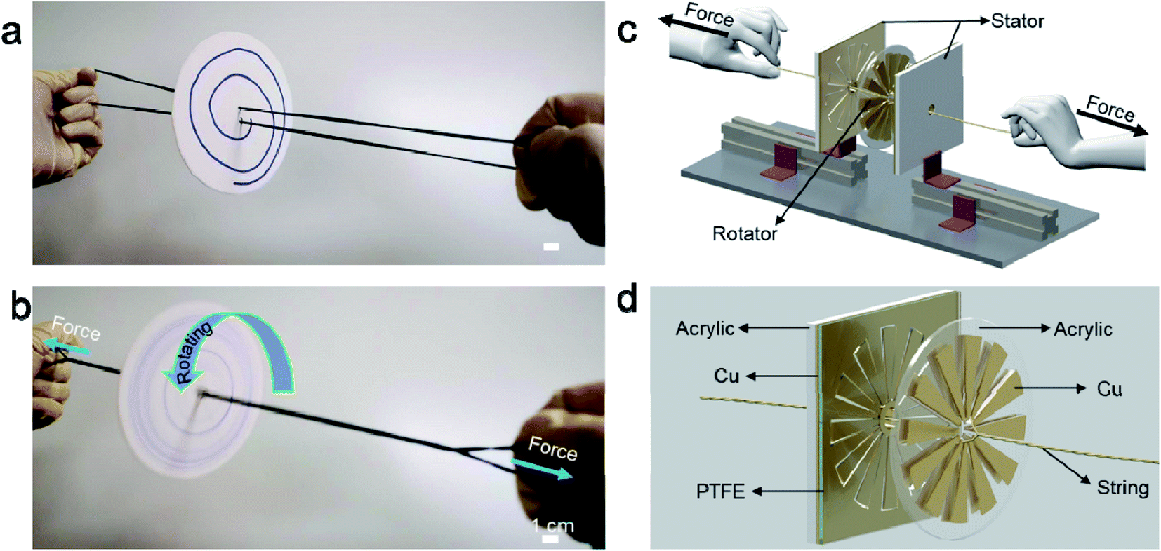 | ||
| Fig. 1 Device principle display and device schematic diagram. (a and b) A whirligig toy made by paper disc and string. (c and d) The conceptional schematic of the hand-powered TENG system. | ||
Fig. 2a illustrates the basic working mechanism of the TENG unit, which is based on the conjugation of triboelectrification and electrostatic induction. Ascribing to the rotary triboelectrification, the isolated Cu layer on the rotator would be positively charged with the surface of the PTFE film be negatively charged. Accompanied by the relative rotation of the rotator and the stator, the movement of the positively charged Cu section would induce charge transferring between the two electrodes through an external circuit, thus producing current.18–20 Fig. 2b–d display the output performance of this hand-powered TENG device. Considering that the contact between the rotor and the stator is controlled artificially, the distance between the rotor and the stator needs to be adjusted when pulling the strings rhythmically in order to generate electric energy. Especially when the device with only one stator, the time interval between the two contacts of rotor and stator is relatively long, which is not conducive to the efficient harvesting of mechanical energy. Exhibited by Fig. 2b, when the device is operated at a frequency of about 1 Hz, the interval between the two signals is about 2 seconds for this case. Therefore, two stators were placed on both sides of the rotor to harvest mechanical energy more efficiently. In this way, the interval between output signals can be obviously shortened (Fig. 2c). From the enlarged picture, it can be seen that the device completed about 30 charge transfer cycles in 20 ms (Fig. 2d). According to the number of blades (12 blades), the rotational speed of the device is about 7500 rpm.21 This rotational speed is significantly higher than other sliding mode TENGs driven by human-power or wind.22,23 The output voltage of the TENG remained as high as ∼300 V and short-circuit current was approximately 65 μA (Fig. S3†). Which are significantly higher than the recently published work with similar structure.24 At the same time, even compared with other device also has very high speed (∼7500 rpm), the performance of this device is still better.19 The non-uniformity of the signal is mainly due to the difficulty of keeping the stability of the contact between the rotor and the stator under manual condition.
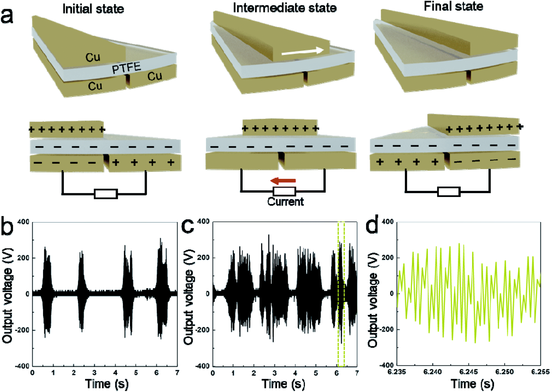 | ||
| Fig. 2 Working mechanism and performance characterization. (a) Working mechanism of the hand-powered TENG. (b) Open-circuit voltage of the device with only one stator. (c) Open-circuit voltage of the device with two stators on both sides of the rotor. (d) The enlarged picture of the yellow dashed box in (c). | ||
In addition, we tested the TENG in the presence of external electrical resistance loads and determined its effectiveness in power generation (Fig. 3a). With increasing electrical resistance loads ranging from 104 to 109 Ω, the instantaneous voltage peak increased while the current density peak decreased, showing a trade-off phenomenon. As a result, the instantaneous power output reached a maximum value of 0.65 W m−2 at the external load resistance of 2 × 10⁶ Ω (Fig. 3b, Wd = Ipeak2R). Fig. 3c illustrates that the “CUG” logo consisting of 28 serially connected green LEDs can be lit directly by the electricity generated from the porous-pyramid-based TENG without any external energy sources (Mov. S2†). In order to demonstrate the high power generation of the developed TENG device, commercial capacitors were utilized to store the generated electrical energy with an AC to DC signal converting circuit. Capacitors with capacities of 10 μF can be quickly charged to ∼15 V, while a relatively large capacitor (33 μF) can reach a voltage of ∼5 V within 60 s (Fig. 3d). By contrast, when using the device with only one stator, capacitors with capacities of 10 μF can only be charged to ∼2.5 V within 60 s. Additionally, a 33 μF capacitor was chosen as a storage component to power an electronic watch and an electronic thermometer after a charging process supported by the TENG. The photographs in Fig. 3e and f suggest that the electronic watch and the thermometer were successfully powered by the capacitor after charged by the TENG (Fig. S4†). Specifically, the voltage of the capacitor reaches around 2.0 V in ∼25 s and can later power the watch for more than 15 s (Mov. S3†). Accordingly, the maximum capacitor voltage of about 6.0 V was attained in ∼80 s and can support the thermometer for more than 5 s (Mov. S4†).
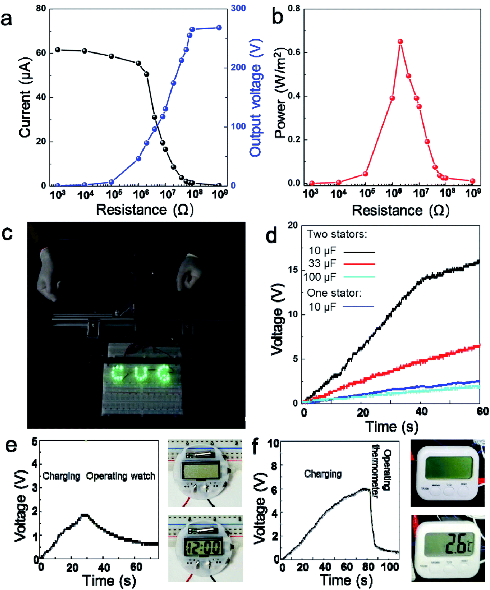 | ||
| Fig. 3 Application of the hand-powered TENG. (a) Output voltage and current of the TENG with external resistance loads ranging from 103 to 109 Ω. (b) Output power under same experimental conditions as (a). (c) Lighting of 28 green serially connected LEDs by the hand-powered TENG. (d) Measured voltage of commercial capacitors (10, 33, 100 μF) charged with a hand-powered TENG with two stators and the measured voltage of commercial capacitor (10 μF) charged with a hand-powered TENG with one stator, respectively. (e and f) Voltage profile of 33 μF capacitor charged by the hand-powered TENG and used to power electronic watch (e) or thermometer (f). | ||
As mentioned above, centrifugation is important especially for dealing with whole blood samples.25 The process of separating plasma or serum by centrifugation is frequently required. In view of its importance, we demonstrate how the rotor part can be utilized as a field-portable, ultralow-cost centrifugation tool (Fig. S5†). Firstly, we filled capillaries by 20 μl of whole human blood (from a finger-prick), then spun them with the rotor. The result reveals complete separation of plasma from the red blood cells (RBC) within 1.5 min (Fig. S5c†) at an operation frequency of 1 Hz. The speed of centrifugation can be controlled by the speed of pulling the strings. When organized in a system, the TENG can simultaneously separate the component need to be detected from complex solutions and harvest mechanical energy to supply power for an electrochemical sensor. Thus, centrifugal pretreatment and analysis can be achieved without additional power supply, as schematically illustrated in Fig. 4a. Considering the low cost for fabrication and maintenance, the hand-powered TENG system could be promising for portable biochemical analysis outdoors or in harsh environment and capable to be integrated with more types of sensors. In order to further demonstrate the function of the system, the system is used to realize the centrifugal treatment of lake water and the detection of H2O2 content in lake water. The reasons for choosing H2O2 as the target are as follow. H2O2 is a key species in many environmental processes such as the electro-Fenton system to remove organic pollutants in wastewater treatment.26 To investigate the relationship between the generation of H2O2 and the degradation of pollutants, rapid and accurate detection of H2O2 in situ is needed. Here, a hydrogen peroxide sensor (Fig. 4c) has been developed based on silver microbelt (Fig. S6†), which was powered by recovering the mechanical energy during centrifugation. As shown in Fig. 4d, after centrifugation, the impurities in the turbid lake water are well separated. Then, the supernatant was dropped onto the H2O2 sensor to realize the detection. Fig. 4e shows the amperometric responses of the Ag microbelt device in the presence of H2O2 polluted lake water with different concentrations. A capacitor (100 μf) was charged to 3 V to work as power supply of the H2O2 sensor. It is worth noting that, for the sake of safety, the centrifugal process and the power generation process are completed separately.
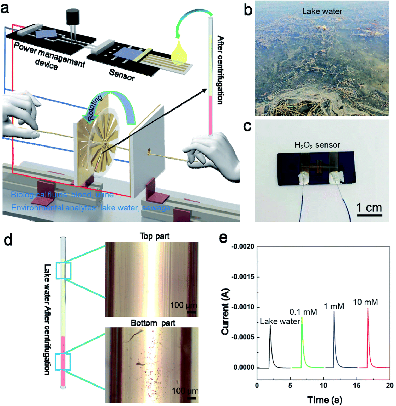 | ||
| Fig. 4 (a) Schematic of the battery-free point-of-care diagnostic system which can realize manual centrifugal and detection at the same time. (b) Photo of lake water. (c) photo of the H2O2 sensor. (d) Microscopic images of the lake water after centrifugation. (e) The amperometric responses of the Ag microbelt device in the presence of H2O2 polluted lake water with different concentration. | ||
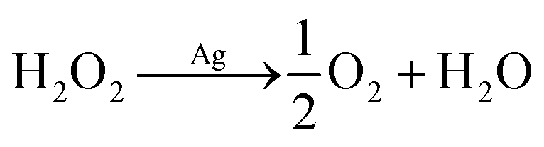
Because Ag microbelt is essentially a resistance, the conductivity of Ag microbelt increases with the increase of H2O2 concentration. According to the literature,27 the mechanism of H2O2 electroreduction can be expressed as follows:
H2O2 + e− ![[left over right harpoons]](https://www.rsc.org/images/entities/char_21cb.gif) OH(ad) + OH− OH(ad) + OH− |
| OH(ad) + e− OH− |
| 2OH− + 2H+ 2H2O |
Then the O2 generated in the action above would turn into the detection signal on electrode. It has been proposed that the electroreduction of oxygen on electrode occurred via the mechanism shown below.28
| O2 + e− [O2˙−](ads) |
Then
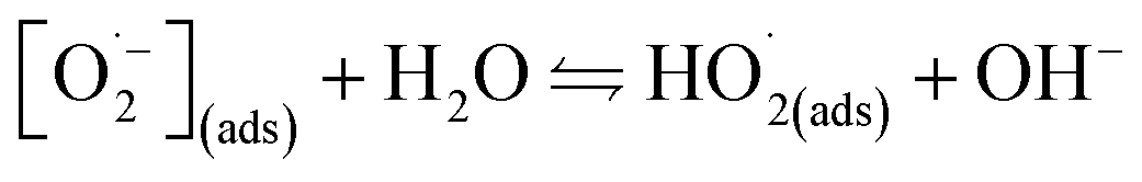
or
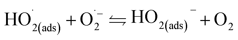
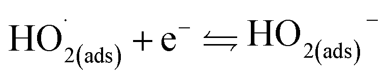
And the measured current density increases with an increase in the concentration of H2O2.29 Therefore, it can be seen that, the current signal increases with the increase of H2O2 concentration. At the same time, it can be seen from Fig. S7† that the voltage of the capacitor used as the power supply decreases more quickly due to the decrease of the resistance of the Ag microbelt band after dropping with lake water containing 10 mM H2O2. Finally, the pretreatment of lake water and the detection of H2O2 in it can be realized through the system.
Conclusions
In summary, we have demonstrated a hand-powered TENG system, which can simultaneously realize manual centrifugal and rotary mechanical energy harvesting. The rotator part can work as centrifuge and separate pure plasma from whole blood in less than 1.5 min. Moreover, the rotating mechanical energy can be recycled to power different electronic devices, such as electronic watch or thermometer. The system exhibits the potential for battery-free point-of-care diagnostic devices due to manual pre-processing and self-powered ability. As a demonstration, we realized the centrifugation of turbid lake water. At the same time, the power generated by centrifugation is used to detect H2O2 in the lake water. More importantly, the simplicity of manufacturing the proposed device could enable mass distribution of the solution analysis, which is urgently needed in the field.Methods
TENG fabrication
The acrylic substrates (2 mm thick) of the stator and rotator were prepared using laser cutting according to the design in Fig. S1 in the ESI.† Two Cu films were pasted onto the inner and outer sections of the stator to function as the electrodes and then covered by a PTFE film (80 μm thick) as one triboelectric material. Cu films (60 μm thick) were partially pasted onto the rotator.H2O2 sensor fabrication
The silver and reducing solutions were prepared according to the typical protocol of the Tollens' reaction for Ag nanoparticle synthesis with the assistance of microfluidic device. First, the silver solution was prepared by adding silver nitrate (1.7 g) to deionized water (20 mL) with potassium hydroxide (40 μL, 0.25 M). Ammonium hydroxide (28–32%) (∼1.7 mL) was then added until the solution became clear and transparent again. Second, the reducing solution was prepared by dissolving D-glucose (6.84 g) in deionized water (20 mL) and then adding absolute methanol (10 mL) to the obtained solution. The as-prepared PDMS device was placed on a piece (1.5 × 3 cm2 in size) of silicon dioxide (300 nm in thickness)/silicon wafer (SiO2/Si wafer) and kept on a square dish with water-soaked paper for maintaining proper humidity.Characterization
The open-circuit voltage of the TENG was measured using a digital phosphor oscilloscope (MSO 2024B, Tektronix, Inc., Beaverton, OR, USA) and a low-noise current preamplifier (model no. SR570, Stanford Research Systems, Inc., Sunnyvale, CA) were used for electrical measurements. Amperometric response of the H2O2 sensor was measured by an electrochemical workstation (Chenhua, Shanghai).Live subject statement
The study protocol for live subjects (human blood samples) was approved by the Ethical Committee of China University of Geosciences. And all experiments were performed in compliance with the relevant laws and institutional guidelines of People's Republic of China. Informed consent was acquired for any experimentation requiring human blood samples.Conflicts of interest
There are no conflicts to declare.Acknowledgements
This work was supported by the National Natural Science Foundation of China (22004112, 22090050 and 21874121), the National Key Research and Development Program of China (2018YFE0206900), the Mid-Career Researcher Program through a National Research Foundation of Korea (NRF) grant funded by the Korean government (NRF-2019R1A2C2009822).References
- H. Guo, J. Chen, L. Wang, A. C. Wang, Y. Li, C. An, J.-H. He, C. Hu, V. K. S. Hsiao and Z. L. Wang, Nat. Sustain., 2020, 4, 147–153 CrossRef.
- X.-S. Zhang, M. Han, B. Kim, J.-F. Bao, J. Brugger and H. Zhang, Nano Energy, 2018, 47, 410–426 CrossRef CAS.
- Z. L. Wang, ACS Nano, 2013, 7, 9533–9557 CrossRef CAS PubMed.
- Z. L. Wang, Faraday Discuss., 2015, 176, 447–458 RSC.
- Z. L. Wang, J. Chen and L. Lin, Energy Environ. Sci., 2015, 8, 2250–2282 RSC.
- Z. L. Wang and A. C. Wang, Materials Today, 2019, 30, 34–51 CrossRef CAS.
- H. Ryu, H.-J. Yoon and S.-W. Kim, Adv. Mater., 2019, 31, 1802898 CrossRef PubMed.
- Z. Liu, H. Li, B. Shi, Y. Fan, Z. L. Wang and Z. Li, Adv. Funct. Mater., 2019, 29, 1808820 CrossRef.
- X. Li, G. Xu, X. Xia, J. Fu, L. Huang and Y. Zi, Nano Energy, 2019, 56, 40–55 CrossRef CAS.
- W. Xu, M.-C. Wong and J. Hao, Nano Energy, 2019, 55, 203–215 CrossRef CAS.
- H. Jung, M. Park, M. Kang and K.-H. Jeong, Light. Sci. Appl., 2016, 5, e16009 CrossRef PubMed.
- J. Hwang, S. Lee and J. Choo, Nanoscale, 2016, 8, 11418–11425 RSC.
- M. S. Bhamla, B. Benson, C. Chai, G. Katsikis, A. Johri and M. Prakash, Nat. Biomed. Eng., 2017, 1, 1–7 CrossRef.
- D. Mabey, R. W. Peeling, A. Ustianowski and M. D. Perkins, Nat. Rev. Microbiol., 2004, 2, 231–240 CrossRef CAS PubMed.
- S. Niu, Y. Liu, S. Wang, L. Lin, Y. S. Zhou, Y. Hu and Z. L. Wang, Adv. Mater., 2013, 25, 6184–6193 CrossRef CAS PubMed.
- T. Jiang, X. Chen, K. Yang, C. Han, W. Tang and Z. L. Wang, Nano Res., 2016, 9, 1057–1070 CrossRef.
- I.-W. Tcho, S.-B. Jeon, S.-J. Park, W.-G. Kim, I. K. Jin, J.-K. Han, D. Kim and Y.-K. Choi, Nano Energy, 2018, 50, 489–496 CrossRef CAS.
- Z. Li, J. Chen, H. Guo, X. Fan, Z. Wen, M.-H. Yeh, C. Yu, X. Cao and Z. L. Wang, Adv. Mater., 2016, 28, 2983–2991 CrossRef CAS PubMed.
- J. Chen, W. Tang, K. Han, L. Xu, B. Chen, T. Jiang and Z. L. Wang, Adv. Mater. Technol., 2019, 4, 1800560 CrossRef.
- C. Chen, Z. Wen, A. Wei, X. Xie, N. Zhai, X. Wei, M. Peng, Y. Liu, X. Sun and J. T. W. Yeow, Nano Energy, 2019, 62, 442–448 CrossRef CAS.
- M.-L. Seol, R. Ivaškevičiūtė, M. A. Ciappesoni, F. V. Thompson, D.-I. Moon, S. J. Kim, S. J. Kim, J.-W. Han and M. Meyyappan, Nano Energy, 2018, 52, 271–278 CrossRef CAS.
- Y. Yun, S. Jang, S. Cho, S. H. Lee, H. J. Hwang and D. Choi, Nano Energy, 2020, 80, 105525 CrossRef.
- Y. Xi, H. Guo, Y. Zi, X. Li, J. Wang, J. Deng, S. Li, C. Hu, X. Cao and Z. L. Wang, Adv. Energy Mater., 2017, 7, 1602397 CrossRef.
- Y. Zou, J. Xu, Y. Fang, X. Zhao, Y. Zhou and J. Chen, Nano Energy, 2021, 83, 105845 CrossRef CAS.
- M. Hasanzadeh and N. Shadjou, Trac. Trends Anal. Chem., 2016, 80, 167–176 CrossRef CAS.
- Z. Li, Y. Jiang, C. Liu, Z. Wang, Z. Cao, Y. Yuan, M. Li, Y. Wang, D. Fang and Z. Guo, Environ. Sci. Nano, 2018, 5, 1834–1843 RSC.
- M. Honda, T. Kodera and H. Kita, Electrochim. Acta, 1986, 31, 377–383 CrossRef CAS.
- J. Xu, W. Huang and R. L. McCreery, J. Electroanal. Chem., 1996, 410, 235–242 CrossRef.
- D.-J. Kim, D. Ha, Q. Zhou, A. K. Thokchom, J. W. Lim, J. Lee, J. G. Park and T. Kim, Nanoscale, 2017, 9, 9622–9630 RSC.
Footnote |
| † Electronic supplementary information (ESI) available. See DOI: 10.1039/d1ra03323a |
| This journal is © The Royal Society of Chemistry 2021 |