DOI:
10.1039/D1RA02973H
(Paper)
RSC Adv., 2021,
11, 20258-20267
Magnetic Fe3O4@CoFe-LDH nanocomposite heterogeneously activated peroxymonosulfate for degradation of azo-dye AO7†
Received
16th April 2021
, Accepted 21st May 2021
First published on 7th June 2021
Abstract
In this study, a novel core@shell magnetic nanocomposite Fe3O4/CoFe-layered double hydroxide (Fe3O4@CoFe-LDH) was successfully synthesized by the co-precipitation method, and then employed as an efficient heterogeneous catalyst for activation of peroxymonosulfate (PMS) in removal of azo-dye acid orange 7 (AO7). The as-obtained nanocomposite was characterized by X-ray diffraction (XRD), Fourier transform infrared spectroscopy (FT-IR), scanning electron microscopy (SEM) and vibrating sample magnetometer (VSM). The results from these characterizations showed Fe3O4@CoFe-LDH to possess good ferromagnetism and a perfect crystalline structure with a typical core@shell morphology. The system of Fe3O4@CoFe-LDH11/PMS (cobalt![[thin space (1/6-em)]](https://www.rsc.org/images/entities/char_2009.gif) :
:![[thin space (1/6-em)]](https://www.rsc.org/images/entities/char_2009.gif) iron molar ratio of 1
iron molar ratio of 1![[thin space (1/6-em)]](https://www.rsc.org/images/entities/char_2009.gif) :
:![[thin space (1/6-em)]](https://www.rsc.org/images/entities/char_2009.gif) 1) achieved 95.1% removal rate of AO7 (40 mg L−1) within 15 min under the optimized conditions, which outperformed bare Fe3O4 and raw CoFe-LDH11. Meanwhile, Fe3O4@CoFe-LDH11 displayed good adaptability in a wide pH range from 4 to 9 and relatively low PMS activation energy (39.9 kJ mol−1). The interference tests revealed HCO3− to possess the strongest restriction effect. Only 57.7% AO7 was removed when 10 mM HCO3− was introduced, which was ascribed to HCO3− not only serving as a radical scavenger, but also increasing the pH of the system. The radical quenching tests demonstrated SO4˙− as the dominant reactive species during the catalytic reaction. Based on X-ray photoelectron spectroscopy (XPS) analysis, the core structure of Fe3O4 served as an electron donor for accelerating the cycle of Co(II)/Co(III) at the active site of the LDH outer shell. Also, Fe3O4@CoFe-LDH exhibited outstanding stability and recyclability, and maintained high degradation efficiency of AO7 even after five cycles. In sum, the proposed magnetic Fe3O4@CoFe-LDH nanocomposite has great potential for remediation of wastewater contaminated with synthetic dyes.
1) achieved 95.1% removal rate of AO7 (40 mg L−1) within 15 min under the optimized conditions, which outperformed bare Fe3O4 and raw CoFe-LDH11. Meanwhile, Fe3O4@CoFe-LDH11 displayed good adaptability in a wide pH range from 4 to 9 and relatively low PMS activation energy (39.9 kJ mol−1). The interference tests revealed HCO3− to possess the strongest restriction effect. Only 57.7% AO7 was removed when 10 mM HCO3− was introduced, which was ascribed to HCO3− not only serving as a radical scavenger, but also increasing the pH of the system. The radical quenching tests demonstrated SO4˙− as the dominant reactive species during the catalytic reaction. Based on X-ray photoelectron spectroscopy (XPS) analysis, the core structure of Fe3O4 served as an electron donor for accelerating the cycle of Co(II)/Co(III) at the active site of the LDH outer shell. Also, Fe3O4@CoFe-LDH exhibited outstanding stability and recyclability, and maintained high degradation efficiency of AO7 even after five cycles. In sum, the proposed magnetic Fe3O4@CoFe-LDH nanocomposite has great potential for remediation of wastewater contaminated with synthetic dyes.
1. Introductions
Synthetic dyes are chemical products widely used in the textile, leather, paper, cosmetics, and other industries.1 The increasing demand for dye production has led to the discharge of large quantities of wastewater, thereby contaminating natural water bodies and causing severe environmental problems. Besides, most of the dyes are toxic and resist natural degradation.2 Hence, the elimination of dyes from water bodies is of great importance for environmental remediation and public health. Numerous reports have so far been published on the removal of dyes from aquatic environments by means of adsorption,3 microbiological treatment,4 electrochemistry,5 photolysis,6,7 and so on. Unfortunately, these strategies do not meet the actual requirement due to complex operational management, low removal rates and high energy consumption.8 By comparison, advanced oxidation processes (AOPs) are ideal and appropriate for the treatment of non-biodegradable pollutants.9,10
Recently, sulfate radical-based advanced oxidation processes (SR-AOPs) have attracted increasing attention due to their high redox potentials (2.5–3.1 V) and selectivity of sulfate radicals (SO4˙−).11 Compared to HO˙ (1.9–2.7 V), the benchmark of radicals utilized for AOPs, SO4˙− possesses stronger oxidation capacity and longer half-life (30–40 μs, HO˙ less than 1 μs).12 Therefore, SR-AOPs exhibit better degradation and mineralization performances toward intractable contamination of water bodies. In general, SO4˙− is produced by activation of peroxymonosulfate (PMS) or peroxydisulfate (PDS) as an oxidant.13 SR-AOPs can be divided into thermolysis, ultrasonic, photocatalysis, electrocatalysis, and transition metal activation.14 Among the above activation strategies, transition metal activation has extensively been employed owing to its lower energy-input and higher degradation rate. According to previous studies, cobalt ion (Co2+) displayed the best catalytic properties in PMS activation.15 However, the lack of effective methods for recovering Co2+ from wastewater may cause secondary pollution and threaten both the ecological environment and human health.16 Hence, employing cobalt-based heterogeneous catalysts as PMS activators is a promising for the treatment of wastewater contaminated by dyes.
Due to the rich active sites and unique hierarchical architectures, two-dimensional (2D) materials, such as graphene and layered double hydroxides (LDH), have been considered as perfect PMS activator.17,18 LDH are multi-metal layered clay materials, consisting of positive metal cations (divalent metals and trivalent metals) and interlayer negative anions (NO3−, Cl−, CO32−, etc.). The unique layered structure of LDH combined with its tuneable controllability of metal ions and structural stability made these materials promising for water splitting, energy storage and environmental remediation.19–21 For instance, Guo et al. successfully synthesized CoCu-LDH composites with great performance in PMS activation for removal of lomefloxacin.22 Zhao et al. reported that CoMn-LDH/PMS system achieved 52.2% TOC removal rate of acid orange G.23 Hence, cobalt-based LDH catalysts look efficient for the activation of PMS. However, the catalyst agglomeration might significantly impede the catalytic performance of LDH.24 Moreover, nanoparticle catalysts are difficult to separate and recover from the water bodies, thereby limiting their practical applications. Previous literature demonstrated Fe3O4 as an eco-friendly and non-toxic carrier with high magnetic separation force.25,26 For example, Jung et al. reported magnetic Fe3O4@MgAl-LDH adsorbent with large specific surface area, possessed much greater adsorption capacity for iodide.27 However, despite the extensive investigation of LDH coating on Fe3O4 with fast separation and recovery properties, little is still known about Fe3O4@LDH as a heterogeneous catalyst for PMS activation and wastewater purification.
Herein, a novel core@shell Fe3O4@CoFe-LDH was synthesized and applied for PMS activation in azo-dye AO7 degradation. The nanocomposite was prepared via a simple co-precipitation method and characterized by various analytical methods. The different reaction systems and effects of various parameters like Co/Fe molar ratio, pH, temperature, PMS dosage, and catalyst concentration were all systematic studied. The influences of common inorganic anions found in an aquatic environment on Fe3O4@CoFe-LDH/PMS performances were also tested to evaluate the interference capability. The as-obtained nanocomposite did not only exhibit great degradation rate of AO7, but also completely recovered from the aquatic environment through the application of an external magnetic field. Scavenging experiments were also carried out to identify the major involved radicals and possible reaction mechanisms. Overall, the developed magnetic nanocomposites showed good stability as PMS heterogeneous catalyst for dye wastewater treatment.
2. Experimental procedure
2.1. Materials
All chemical reagents used in this study were of analytical grade without further purification. Ferric chloride hexahydrate (FeCl3·6H2O, 99.0 wt%), sodium dihydrogen phosphate (NaH2PO4, 99.0 wt%), ethylene glycol (EG, 99.0 wt%), polyvinylpyrrolidone (PVP, MW = 40![[thin space (1/6-em)]](https://www.rsc.org/images/entities/char_2009.gif) 000), acid orange 7 (AO7, 99.0 wt%) and peroxymonosulfate (2KHSO5·KHSO4·K2SO4, 98.0 wt%) were purchased from Adamas-Beta Reagent Co., Ltd. Sodium hydroxide (NaOH, 98.0 wt%), sodium carbonate (Na2CO3, 99.8 wt%), sodium hydrogen carbonate (NaHCO3, 99.5 wt%), sodium acetate (NaAc, 99.0 wt%), and tert-butanol (TBA, 99 wt%) were purchased from Shanghai Titan Scientific Co., Ltd. Cobalt chloride hexahydrate (CoCl2·6H2O, 98.0 wt%) and sulfuric acid (H2SO4) were purchased from Sinopharm Chemical Reagent Co., Ltd. All chemicals were commercially available. Deionized (DI) water was used to prepare solutions throughout the study.
000), acid orange 7 (AO7, 99.0 wt%) and peroxymonosulfate (2KHSO5·KHSO4·K2SO4, 98.0 wt%) were purchased from Adamas-Beta Reagent Co., Ltd. Sodium hydroxide (NaOH, 98.0 wt%), sodium carbonate (Na2CO3, 99.8 wt%), sodium hydrogen carbonate (NaHCO3, 99.5 wt%), sodium acetate (NaAc, 99.0 wt%), and tert-butanol (TBA, 99 wt%) were purchased from Shanghai Titan Scientific Co., Ltd. Cobalt chloride hexahydrate (CoCl2·6H2O, 98.0 wt%) and sulfuric acid (H2SO4) were purchased from Sinopharm Chemical Reagent Co., Ltd. All chemicals were commercially available. Deionized (DI) water was used to prepare solutions throughout the study.
2.2. Synthesis of magnetic Fe3O4@CoFe-LDH
Fe3O4 nanospheres were prepared via the solvothermal method with some modifications.28 Briefly, FeCl3·6H2O (10 mmol) and sodium acetate (52 mmol) were dissolved in 66 mL of ethylene glycol. After vigorously stirred for 30 min, the mixed solution was transferred to a 100 mL Teflon-lined stainless-steel autoclave and then heated at 473 K for 8 h. Finally, the obtained black precipitate was washed with DI and ethanol for several times, and dried at 333 K in an oven for 24 h.
As illustrated in Fig. 1, the magnetic Fe3O4@CoFe-LDH composites were synthesized via a simple co-precipitation method. FeCl3·6H2O (5 mmol) and CoCl2·6H2O (5 mmol) were dissolved in 100 mL DI water and stirred constantly for 30 min at ambient temperature. Then, the alkaline contained NaOH (0.5 M) and Na2CO3 (0.2 M) was slowly added to the above solution with mechanical stirring (300 rpm) until pH reached 6.5. Subsequently, PVP (1.0 g) and as-prepared Fe3O4 (0.5 g) were added into the mixed solution under the ultrasound for 15 min at 298 K. The metal cation in mixed solution would be adsorbed on the surface of PVP modified Fe3O4 through the effect of electrostatic force of attraction. The pH of mixture was adjusted to 10 by the above-mentioned alkaline. The obtained suspension was aged at 338 K for 24 h. Finally, the products were collected by external magnetic field, washed with deionized water and ethanol, and dried overnight in oven at 333 K. The obtained red-brown composites were labeled as Fe3O4@CoFe-LDH11. Meanwhile, other materials with different Co/Fe ratios (4![[thin space (1/6-em)]](https://www.rsc.org/images/entities/char_2009.gif) :
:![[thin space (1/6-em)]](https://www.rsc.org/images/entities/char_2009.gif) 1, 2
1, 2![[thin space (1/6-em)]](https://www.rsc.org/images/entities/char_2009.gif) :
:![[thin space (1/6-em)]](https://www.rsc.org/images/entities/char_2009.gif) 1, 1
1, 1![[thin space (1/6-em)]](https://www.rsc.org/images/entities/char_2009.gif) :
:![[thin space (1/6-em)]](https://www.rsc.org/images/entities/char_2009.gif) 2, 1
2, 1![[thin space (1/6-em)]](https://www.rsc.org/images/entities/char_2009.gif) :
:![[thin space (1/6-em)]](https://www.rsc.org/images/entities/char_2009.gif) 4, total metal concentration is 10 mmol) were synthesized based on the above method, and labeled as Fe3O4@CoFe-LDH41, Fe3O4@CoFe-LDH21, Fe3O4@CoFe-LDH12 and Fe3O4@CoFe-LDH14. Bare CoFe-LDH11 was also made in the absence of Fe3O4 for the control comparison. And, the detailed information of preparation method of CoFe2O4 was shown in the ESI (Text S1).†
4, total metal concentration is 10 mmol) were synthesized based on the above method, and labeled as Fe3O4@CoFe-LDH41, Fe3O4@CoFe-LDH21, Fe3O4@CoFe-LDH12 and Fe3O4@CoFe-LDH14. Bare CoFe-LDH11 was also made in the absence of Fe3O4 for the control comparison. And, the detailed information of preparation method of CoFe2O4 was shown in the ESI (Text S1).†
 |
| | Fig. 1 Schematic illustration of the synthetic route of Fe3O4@CoFe-LDH. | |
2.3. Characterizations
The phase structure of as-fabricated catalyst was identified by an X-ray diffraction (XRD, Ultima IV, Rigaku, Japan) using Cu Kα radiation (λ = 1.54056 Å, 40 kV, 20 mA) in the range of 5–90° at a scan rate of 2° min−1. The surface functional group of the composites was examined by Fourier transform infrared spectroscopy (FTIR, Thermo Nicolet IS10, Nicolet, USA) at room temperature. The morphology and chemical analysis were recorded on a scanning electron microscope (SEM, Gemini 300, ZEISS, Germany) equipped with an energy-dispersive X-ray spectrometer system (EDS, Quantax 400, Bruker, Germany). The specific surface area and porosity were analyzed using N2 adsorption/desorption experiment (ASAP-2460, Micromeritics, USA). The magnetic properties of synthesized materials were measured at room temperature on a vibrating sample magnetometer (VSM, PPMS-9, Quantum Design, USA). The surface characteristics of the fresh and used samples were measured by the X-ray photoelectron spectroscopy (XPS, ESCALAB 250Xi, Thermo Fisher Scientific, USA). The binding energies of photoelectron peaks was corrected by referring to the binding energy of the C 1s neutral carbon peak at 284.6 eV.
2.4. Degradation experiments
All the degradation experiments were carried out in a 250 mL beaker containing 100 mL of AO7 (40 mg L−1) at 298 K with mechanical stirring. In a typical procedure, the solid catalyst was added into the AO7 solution and mechanical stirred at 250 rpm for 5 min to dispersed completely. Subsequently, 0.12 mM of PMS was injected into the above solution. The initial pH of reaction system was adjusted to 6.0 by NaOH (0.1 M) and H2SO4 (0.1 M) immediately. Within a predetermined interval, 2 mL samples were withdrawn from the beaker, filtered with 0.45 μm PES syringe filter, mixed with 100 μL of Na2S2O3 solution (0.05 M) to quench the residual radicals, and then analyzed at wavelength of 484 nm on a UV-vis spectrophotometer (DR 3900, HACH, USA). For the cycling test, catalysts were collected by external magnet and washed with DI and ethanol for three times before the next run. For the quenching experiments, 10 or 100 mM of radical scavengers (TBA or ethanol) were mixed with AO7 solution before the catalyst and PMS were introduced.
3. Results and discussion
3.1. Characterization
As shown in Fig. 2a, the XRD peaks of bare Fe3O4 could be observed at 2θ of 30.2°, 35.6°, 43.2°, 57.2° and 62.8°, matched well with cubic iron oxide phase (JCPDS no. 19-0629). The main peaks of bare CoFe-LDH11 were located at 11.6°, 23.4°, 34.0°, 38.7°, 38.7°, 46.0°, 59.1° and 60.6°, indexed to (003), (006), (012), (015), (018), (110) and (113) facets of LDH (JCPDS no. 50-0235), respectively, which were consistent with the results in the previous works.29 Besides, the dominant peaks of magnetic Fe3O4@CoFe-LDH11 appeared at 2θ of 11.6°, 23.6°, 30.3°, 34.0°, 35.6°, 38.6°, 43.2°, 46.0°, 57.3°, 60.6°, 62.8° and 63.0°, which were familiar with both phase of pure Fe3O4 and LDH. Due to the unique structure of Fe3O4@CoFe-LDH11, it was observed that XRD peaks was weaker than bare Fe3O4 and CoFe-LDH11. These results suggested that the hybrids were successfully synthesized and consisted of Fe3O4 and LDH.30 The FT-IR spectra of Fe3O4, CoFe-LDH11 and Fe3O4@CoFe-LDH11 are shown in Fig. 2b. Clearly, one may observe that different samples have both three same peaks. The bands at 3418 cm−1, 1630 cm−1 and 1384 cm−1 were assigned to the O–H stretching vibration, bending vibration of hydroxyl deformation mode31 and –OH groups,32 respectively, which might be attribute to H2O molecules adsorbed on the surface of composites and interlayer water of LDH. It is worth noting that the hybrid has a characteristic peak of 1354 cm−1 that disappeared in the Fe3O4, which was ascribed to the vibrational absorption of interlayer anions CO32− of LDH.22 In addition, the absorption peaks at range of 763–471 cm−1 were metal–oxygen (M–O) and metal–hydroxyl (M–OH) groups vibrations. The bands at 763 cm−1 and 471 cm−1 were associated with Co–OH and Co–O stretching vibration.33,34 The peaks located at 627 cm−1 and 586 cm−1 were corresponded to Fe–O stretch vibration,35 while the intensity of Fe3O4@CoFe-LDH11 around 586 cm−1 was sharply decreased than bare Fe3O4 as a result of LDH encapsulated the Fe3O4 nanoparticles. Besides, the magnetic Fe3O4@CoFe-LDH11 showed a sharp band at 627 cm−1, indicating the formation of Fe–O–Fe between Fe3O4 and LDH.30
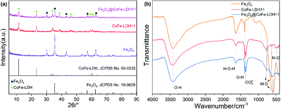 |
| | Fig. 2 XRD patterns (a) and FT-IR spectra (b) of bare Fe3O4, raw CoFe-LDH11 and Fe3O4@CoFe-LDH11. | |
The magnetic properties of Fe3O4 and Fe3O4@CoFe-LDH11 were verified by the vibration sample magnetometry (VSM). As depicted in Fig. 3a, the saturation magnetization (Ms) value of Fe3O4 and Fe3O4@CoFe-LDH11 were 72.48 and 24.15 emu g−1, respectively. Due to the non-magnetic substance LDH coating on the surface of Fe3O4, the magnetic properties of hybrid were weaker than the pristine Fe3O4.36 Despite this, the inset picture of Fig. 3a proved that Fe3O4@CoFe-LDH11 still could be completely separated from the solution within 1 min by external magnetic field, which was beneficial to the recycling of heterogenous catalyst. Moreover, the Fe3O4@CoFe-LDH11 maintained 22.75 emu g−1 of Ms after PMS activation which indicated that it displayed outstanding stability and recyclability. The specific surface area and pore volume of samples were tested by Brunauer–Emmett–Teller method (Fig. 3b). N2 adsorption–desorption isotherms of Fe3O4@CoFe-LDH11 was identified as a type IV curve, which indicated that Fe3O4@CoFe-LDH11 has both microporous and mesoporous pore structures, and the pore diameters of samples shown in the inset figure are at the range of 2–10 nm. Based on the results of Table 1, the specific surface area of Fe3O4@CoFe-LDH11 significantly increased from 46.22 to 122.65 m2 g−1 compared to bare Fe3O4 and was slightly less than that of CoFe-LDH11 which was reason of Fe3O4 core with lower surface area.25 According to the literatures, it was reasonable to speculate that large surface area and rich pore structure of Fe3O4@CoFe-LDH11 might provide more active site for PMS activation and contaminants degradation.37
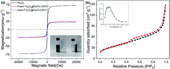 |
| | Fig. 3 The magnetic hysteresis loop of Fe3O4, fresh and used Fe3O4@CoFe-LDH11, the inset showed the separation of Fe3O4@CoFe-LDH11 from solution by external magnetic field (a) and N2 adsorption–desorption isotherms of Fe3O4@CoFe-LDH11 (b). | |
Table 1 Parameters of porous structure of Fe3O4, CoFe-LDH11 and Fe3O4@CoFe-LDH11
| Samples |
Specific surface area (m2 g−1) |
Pore volume (cm3 g−1) |
Average pore size (nm) |
| Fe3O4 |
46.22 |
0.08 |
7.37 |
| CoFe-LDH11 |
158.53 |
0.43 |
10.72 |
| Fe3O4@CoFe-LDH11 |
122.65 |
0.23 |
8.22 |
SEM and EDS were utilized to determine the morphologies and element composition of different samples. As illustrated in the Fig. 4a, the pristine Fe3O4 possessed typical nanospherical structure with diameter of 200–500 nm and has an excellent dispersion. Fig. S3† suggested that CoFe-LDH11 exhibited nanosheet structure which was consistent with the results in the previous reports.38 However, it should be noted that the detrimental effects of agglomeration make the size of LDH increased which might prevent the dye molecules mass diffusion. In the Fig. 4b, the shell of CoFe-LDH wrapped on the surface of Fe3O4 nanosphere, and because of relieving aggregation by Fe3O4 as a carrier, the dimensions of LDH were absolutely tinier than raw LDH. Then, the results of element mapping pictures (Fig. 4c–e) indicated that the Co elements were homogeneously distributed on the surface of Fe3O4. Overall, above results of characterization were compelling lines of evidence that Fe3O4@CoFe-LDH of core@shell structure was prepared successfully.
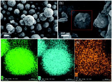 |
| | Fig. 4 SEM images of Fe3O4 (a) and Fe3O4@CoFe-LDH11 (b), EDS mapping of O, Fe, Co for Fe3O4@CoFe-LDH11 (c–e). | |
3.2. AO7 degradation of different catalysts
As shown in Fig. 5a, different reaction systems displayed variable performances toward the removal of target contaminants. The removal rate of AO7 by Fe3O4@CoFe-LDH11 through adsorption reached only 8.3%, while that of other samples was below 8.3%, and can be neglected. Using PMS without LDH and magnetic LDH nanocomposites, only 12% AO7 was degraded after 15 min. Thus, despite the extremely strong oxidation ability of PMS, it cannot directly degrade the organic dye AO7.8 Within 15 min, only 28.2% AO7 was removed in Fe3O4/PMS system due to the inefficient cycling of Fe(II)/Fe(III) on the Fe3O4 surface.12 The other two catalysts, CoFe2O4 and CoFe-LDH11 achieved degradation rates of AO7 reaching 65.3% and 93.4% after 15 min, respectively. By comparison, Fe3O4@CoFe-LDH11/PMS system exhibited the best catalytic performance and PMS activation with 95.1% removal rate within 15 min. All the catalytic systems matched very well with the pseudo-first-order kinetics (eqn (1)).| |
ln![[thin space (1/6-em)]](https://www.rsc.org/images/entities/char_2009.gif) Ct/C0 = −kobst Ct/C0 = −kobst
| (1) |
where C0 is the initial concentration of AO7, Ct is the concentration of AO7 at certain reaction time and kobs (min−1) represents the pseudo-first-order kinetics reaction rate constant for AO7 degradation. The rate constant (kobs) of Fe3O4@CoFe-LDH11 calculated according to eqn (1) and shown in Fig S5a† was 0.549 min−1, a value 2.2-fold that of CoFe-LDH11 (kobs = 0.255 min−1), and 7.7-fold that of the CoFe2O4 (kobs = 0.071 min−1). Among the catalytic systems, the excellent degradation efficiency of Fe3O4@CoFe-LDH11 was attributed to the synergistic effect between LDH and Fe3O4.39 For further comparison, different reported catalysts used for the activation of PMS and degradation of AO7 are listed in Table 2. Fe3O4@CoFe-LDH11/PMS system in this study had relatively high catalytic performances and a fast rate of PMS activation.
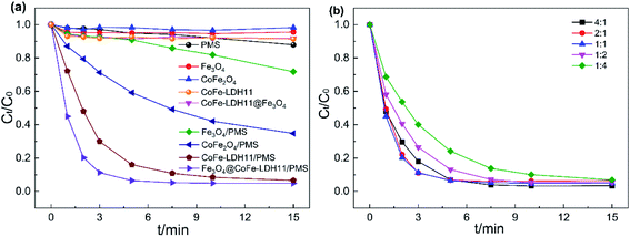 |
| | Fig. 5 AO7 degradation in different system (a) and effect of Co/Fe molar ration on AO7 degradation (b). Experiment conditions: pH = 6, T = 298 K, V = 0.1 L, [AO7] = 40 mg L−1, [catalyst] = 50 mg L−1, [PMS] = 0.12 mM. | |
Table 2 The comparison of AO7 removal efficiency by different catalyst in literatures
| Catalyst (g L−1) |
AO7 concentrations (mg L−1) |
PMS (mM) |
Conditions |
Removal efficiency |
Ref. |
| CoFe2O4 (0.50) |
20 |
0.80 |
pH = 6.3, T = 300 K |
96.0% (40 min) |
37 |
| β-FeOOH (5.70) |
20 |
1.00 |
— |
99.9% (180 min) |
38 |
| Porous CuO (0.05) |
20 |
0.10 |
pH = 8.0, T = 298 K |
85.0% (60 min) |
39 |
| Co3O4@NF (—) |
35 |
0.50 |
— |
98.0% (20 min) |
40 |
| CoCuAl-LDO (0.10) |
20 |
0.16 |
pH = 6.7, T = 298 K |
98.0% (30 min) |
41 |
| MnFe-LDH (0.20) |
20 |
0.33 |
pH = 6.1, T = 298 K |
97.6% (20 min) |
42 |
| Fe3O4@CoFe-LDH11 (0.05) |
40 |
0.12 |
pH = 6.0, T = 298 K |
95.1% (15 min) |
This work |
The effects of Co/Fe molar ratio on AO7 degradation efficiency were also investigated and the results are depicted in Fig. 5b. All samples with different Co/Fe molar ratios displayed good capacity for activating PMS with a removal rate of AO7 reaching 90% within 15 min. As cobalt content increased from 1![[thin space (1/6-em)]](https://www.rsc.org/images/entities/char_2009.gif) :
:![[thin space (1/6-em)]](https://www.rsc.org/images/entities/char_2009.gif) 4 to 1
4 to 1![[thin space (1/6-em)]](https://www.rsc.org/images/entities/char_2009.gif) :
:![[thin space (1/6-em)]](https://www.rsc.org/images/entities/char_2009.gif) 1, the degradation efficiency of AO7 after 5 min varied from 75.9% to 91.7%. Therefore, within this range, the cobalt content played a key role in controlling the reaction rate. Further increase in cobalt content led to the kobs values of Fe3O4@CoFe-LDH11, Fe3O4@CoFe-LDH21 and Fe3O4@CoFe-LDH41 reaching 0.549 min−1, 0.373 min−1 and 0.431 min−1, respectively (Fig. S5b†). However, further raising the molar ratio of cobalt may cause excess divalent cobalt that could react with SO4˙− to generate SO42−. This, in turn, resulted in a slightly declined AO7 degradation rate.40 Hence, a Co/Fe molar ratio of 1
1, the degradation efficiency of AO7 after 5 min varied from 75.9% to 91.7%. Therefore, within this range, the cobalt content played a key role in controlling the reaction rate. Further increase in cobalt content led to the kobs values of Fe3O4@CoFe-LDH11, Fe3O4@CoFe-LDH21 and Fe3O4@CoFe-LDH41 reaching 0.549 min−1, 0.373 min−1 and 0.431 min−1, respectively (Fig. S5b†). However, further raising the molar ratio of cobalt may cause excess divalent cobalt that could react with SO4˙− to generate SO42−. This, in turn, resulted in a slightly declined AO7 degradation rate.40 Hence, a Co/Fe molar ratio of 1![[thin space (1/6-em)]](https://www.rsc.org/images/entities/char_2009.gif) :
:![[thin space (1/6-em)]](https://www.rsc.org/images/entities/char_2009.gif) 1 was selected as the optimal value for subsequent catalytic experiments.
1 was selected as the optimal value for subsequent catalytic experiments.
3.3. Effect of reaction conditions on catalytic activity
3.3.1. Initial value of pH and temperature. The initial pH of the solution plays a key role in the catalytic degradation efficiency of the catalyst/PMS system.41 Thus, the influence of various pH values on AO7 degradation was studied at pH 4 to 10 and the results are presented in Fig. 6a. At pH of 4–9, the removal rate of AO7 reached over 90% after 15 min. The fastest degradation effect was recorded at pH 6 with 94% pollutants degraded in 5 min. According to the previous reports, the pKa1 and pKa2 of PMS are 0 and 9.4, respectively.42 Hence, at pH from 6–9, HSO5− as the main active species of PMS could easily be activated by Fe3O4@CoFe-LDH11 to generate SO4˙− radicals, leading to the fast AO7 degradation rate. As pH gradually decreased, the time required to achieve 90% AO7 removal rate was prolonged. This resulted from the increment in the concentration of H+, causing HSO5− to form more stable species of H2SO5.43 Simultaneously, the formation of CoOH+ could also inhibit catalyst activation of PMS to generate SO4˙−.15 At pH 10, large amounts of OH− could combine with active sites on the catalyst surface to form complexes,37 hindering the direct contact between Fe3O4@CoFe-LDH11 and PMS. This reduced the removal rate of AO7 to 76%. Overall, Fe3O4@CoFe-LDH11/PMS exhibited excellent catalytic degradation of AO7 in a wide range of pH (4–9).
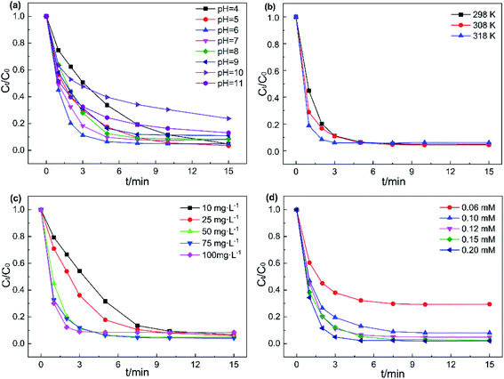 |
| | Fig. 6 Effects of (a) initial of pH, (b) temperature, (c) catalyst concentrations and (d) PMS dosages on AO7 removal efficiency. Experiment conditions: pH = 6 (except a), T = 298 K (except b), V = 0.1 L, [AO7] = 40 mg L−1, [catalyst] = 50 mg L−1 (except c), [PMS] = 0.12 mM (except d). | |
The effects of reaction temperature on AO7 degradation were also studied from 298 K to 318 K. As drawn in the illustration of Fig. 6b and S6a,† Fe3O4@CoFe-LDH11/PMS system achieved 95% AO7 degradation in 7.5 min at room temperature (298 K). By comparison, while at 308 K and 318 K, the time required to achieve 95% AO7 removal were only 5 min and 3 min, respectively. Since PMS activation is an endothermic reaction, the kobs of the reaction system would increase with the temperature. Furthermore, the Arrhenius formula (eqn (2)) was employed to further calculate and analyze the activation energy (Ea) of AO7 degradation.
| |
ln![[thin space (1/6-em)]](https://www.rsc.org/images/entities/char_2009.gif) k = ln k = ln![[thin space (1/6-em)]](https://www.rsc.org/images/entities/char_2009.gif) A − Ea/RT A − Ea/RT
| (2) |
where
k is the pseudo-first-order kinetics reaction rate constant,
A is the preexponential factor,
R and
T was the ideal gas constant and absolute temperature, respectively,
Ea is the activation energy. The
Ea value of Fe
3O
4@CoFe-LDH11/PMS system calculated from Fig. S6b
† was 31.99 kJ mol
−1. Hence, the degradation of AO7 in this system could be facilitated by raising the temperature.
3.3.2. Catalyst concentration and PMS dosage. The effects of catalyst concentration on the degradation rate of AO7 in Fe3O4@CoFe-LDH11/PMS system was investigated and the data are provided in Fig. 6c. The removal efficiency of AO7 within 3 min, as well as the reaction rate constant, both rose with the catalyst concentration. In detail, the degradation rate of AO7 after 5 min increased from 68.3% to 82.2%, 93.5% at catalyst concentration from 10 mg L−1 to 50 mg L−1, respectively. While the catalyst concentration was above 50 mg L−1, the 5 min degradation rate of AO7 was ranged from 91.6% to 93.7%. Hence, a slight enhancement was noticed in AO7 removal efficiency. Increasing the catalyst dosage at lower catalyst concentrations (less than 50 mg L−1) was equivalent to enhancing the number of catalytic active sites in the system. However, the catalyst concentration did not significantly affect the degradation rate of AO7 when the catalyst exceeded the upper limit of the range above 50 mg L−1. In addition, the removal rate of AO7 after 15 min at 100 mg L−1 catalyst concentration was only 91.5%, a value slightly lower than those obtained at 50 mg L−1 and 75 mg L−1 catalyst concentrations, since the excess of catalyst might compete with AO7 and consume SO4˙− radicals generated during PMS activation. As a result, the AO7 degradation rate decreased, consistent with the literature.44 Therefore, 50 mg L−1 was determined as the optimal catalyst concentration.The effect of different PMS dosages on the removal rates of AO7 are presented in Fig. 6d. As PMS dosage increased from 0.06 to 0.12 mM, the degradation efficiency of AO7 increased significantly from 70.5% to 95.1% after 15 min. Besides, a linear growth relationship was recorded between the reaction rate constant k and PMS dosage (Fig. S6d†), indicated that the PMS concentration is the rate-controlling parameter of the catalytic degradation of AO7 under such conditions. Moreover, further increase PMS concentration led to no significant change in AO7 removal efficiency. This could be attributed to the excessive HSO5− which would react with the radicals to produce SO5˙− with a weaker oxidizing ability33 (eqn (3) and (4)). Overall, considering the cost of PMS and the relationship between PMS dosage and degradation rate of AO7, 0.12 mM was selected as optimal PMS dosage for subsequent experiments.
| | |
HSO5− + SO4˙− → SO42− + SO5˙− + H+
| (3) |
| | |
HSO5− + HO˙ → SO5˙− + H+
| (4) |
3.3.3. Effect of inorganic ions. Various inorganic ions exist in actual wastewater bodies, which may affect the degradation process of target contaminants. Hence, the influence of four inorganic anions (Cl−, HCO3−, H2PO4− and NO3−) on the removal of AO7 was investigated and the results are displayed in Fig. 7. NO3− showed almost no obvious effect on AO7 degradation at different concentrations (Fig. 7d and S7,†). Compared to NO3−, Cl− exhibited an inhibitory effect on the catalytic system. After adding 10 mM Cl−, the AO7 removal rate reduced from 95.1% to 77.5% within 15 min. On the one hand, it is generally believed that Cl− could directly react with PMS to generate HOCl in the presence of PMS and Cl− in the system (eqn (4)).45 On the other hand, the generated SO4˙ and HO˙ by PMS activation could also deliver free electrons to Cl− to form radicals of Cl˙ and ClOH˙− (eqn (5) and (6), k(SO4˙− + Cl−) = 2.0 ×10⁸ M−1 s−1, k(HO˙ + Cl−) = 4.3 ×10⁹ M−1 s−1).43 The redox potentials of newly generated free radicals Cl˙ and ClOH˙− were estimated to 2.4 V and 1.5–1.8 V, respectively. As a result, the relative redox capacity of new generated radicals was the reason that led to a decrease in AO7 removal rate.| | |
Cl− + HSO5− → SO42− + HOCl
| (5) |
| | |
Cl− + SO4˙− → SO42− + Cl˙
| (6) |
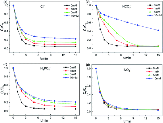 |
| | Fig. 7 Effects of anions on AO7 degradation (a) Cl−, (b) HCO3−, (c) H2PO4− and (d) NO3−. Experiment conditions: pH = 6, T = 298 K, V = 0.1 L, [AO7] = 40 mg L−1, [catalyst] = 50 mg L−1, [PMS] = 0.12 mM. | |
As shown in Fig. 7b and S7b,† the presence of HCO3− significantly inhibited the decomposition of AO7. The addition of 10 mM HCO3− led to only 57.7% removal of AO7. Note that HCO3− is a common free radical scavenger,46 quenching the generated SO4˙ and HO˙ in the catalyst/PMS system according to eqn (8) and (9), to form the less reactive HCO3˙. Furthermore, the introduction of HCO3− would cause the pH of the system rising. Simultaneously, HCO3− has strong buffer capability, which might keep the catalytic system under alkaline conditions.47 With addition of 1–10 mM H2PO4−, the decreasing trend of AO7 removal efficiency was similar to the system with Cl− added. This result can be explained that H2PO4− could transform into phosphate radicals with the assistance of SO4˙ and HO˙.48
| | |
HCO3− + SO4˙− → SO42− + HCO3˙
| (8) |
| | |
HCO3− + HO˙ → CO32− + H2O
| (9) |
3.4. Stability and reusability of Fe3O4@CoFe-LDH
Reusability and stability of catalysts are important when evaluating potential practical applications. Hence, five consecutive cycle experiments were conducted to measure the stability of Fe3O4@CoFe-LDH. As displayed in Fig. 8a, Fe3O4@CoFe-LDH exhibited outstanding reusability and stability after five cycles, with 98.1%, 94.9%, 94.4%, 94.3% and 88.7% AO7 degradation rate for each cycle. However, a slight reduction in AO7 removal rate occurred in the fifth catalytic degradation experiment, which might be explained by several reasons. (i) Loss of Fe3O4@CoFe-LDH active site during the catalytic degradation of AO7. (ii) The intermediate products of AO7 degradation adsorbed on Fe3O4@CoFe-LDH surface, that hindered the contact between the catalyst and PMS in the next run.37 In general, the stability and recyclability shown by Fe3O4@CoFe-LDH in the cycling experiments indicated that the magnetic samples could be used as an ideal heterogeneous catalyst in actual wastewater treatment.
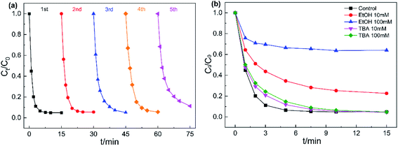 |
| | Fig. 8 Reusability of Fe3O4@CoFe-LDH for the degradation of AO7 (a), effect of TBA and EtOH on AO7 degradation (b). Experiment conditions: pH = 6, T = 298 K, V = 0.1 L, [AO7] = 40 mg L−1, [catalyst] = 50 mg L−1, [PMS] = 0.12 mM. | |
3.5. Reaction mechanism
To verify the free radicals generated in Fe3O4@CoFe-LDH/PMS system, quenching tests were carried out by introducing two common free radical scavengers EtOH and TBA into the degradation system. The reaction rate constants of EtOH with sulfate radical and hydroxyl radical were determined as 3.51 × 10⁷ M−1 s−1 and 9.1 × 10⁶ M−1 s−1 ,23 respectively. EtOH is considered to capture both SO4˙ and HO˙ at the same time. Meanwhile, the reaction rate constants of TBA/SO4˙− and TBA/HO˙ were 4.0–9.1 × 10⁵ M−1 s−1 and 3.8–7.6 × 10⁸ M−1 s−1, thereby generally used as an effective scavenger for HO.49 As illustrated in Fig. 8b, the addition of 10 mM and 100 mM TBA into the system led a mild decrease AO7 degradation efficiency within 10 min. By comparison, AO7 removal rate after 15 min showed almost no obvious change when compared to the control experiment, indicating that Fe3O4@CoFe-LDH/PMS system could generated HO·. As for EtOH, the introduction of 10 mM and 100 mM EtOH into AO7 solution, caused a remarkable declined in the degradation rate with only 77.4% and 35.9% AO7 removed within 15 min. In sum, Fe3O4@CoFe-LDH/PMS system could generate HO˙ and SO4˙− during the catalytic degradation of AO7, while SO4˙− was determined as the dominant species decomposing the AO7 molecules.
To further interpret the reaction mechanism of Fe3O4@CoFe-LDH/PMS system, XPS was employed to analyze the valence states of Fe3O4@CoFe-LDH before and after the degradation reaction. In Fig. 9a, the Co 2p XPS spectrum of fresh Fe3O4@CoFe-LDH was divided into Co 2p3/2 and Co 2p1/2 peaks located at binding energies of 780.5 eV and 796.8 eV,24,43 respectively. Two satellite peaks at 786.2 eV and 802.6 eV were also noticed, and corresponding to Co(II).50 Besides, the peak at 782.4 eV was assigned to Co(III),16 and attributed to the partial oxidation of Co(II) to Co(III) during the process of co-precipitation. After completion of the reaction, the binding energy of the peaks slightly shifted to higher binding energies, and the Co(II)/Co(II) + Co(III) ratio of Fe3O4@CoFe-LDH declined from 70.2% before the reaction to 65.2% after reaction. Thus, a redox process of Co(II)/Co(III) took place on the samples surface during the catalytic reaction. Fe 2p XPS spectra of fresh and used samples are displayed in Fig. 8b. The peak of Fe 2p3/2 was divided into two peaks at 713.0 eV (Fe(III) 2p3/2) and 710.5 eV (Fe(II) 2p3/2), whereas the peak at 724.2 eV was related to Fe 2p1/2 of Fe(III).21,48 After catalytic reaction, no obvious change in the binding energy of Fe 2p was noticed. Additionally, the amount of Fe(III) increased from 60.7% to 69.3% after PMS activation, and the peaks related to Fe(II) were derived from ferrous on the surface of Fe3O4 in Fe3O4@CoFe-LDH. Therefore, the core structure of Fe3O4 would transfer free electrons to Co(II) active sites in the outer shell structure of LDHs.
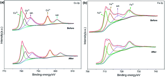 |
| | Fig. 9 XPS spectra of (a) Co 2p and (b) Fe 2p of fresh and used Fe3O4@CoFe-LDH. | |
Based on the above analysis and discussion, the reaction mechanism of PMS activation was proposed for AO7 degradation by Fe3O4@CoFe-LDH. Firstly, PMS was directly activated by Co(II) active sites on Fe3O4@CoFe-LDH surface to generate SO4˙− (eqn (10)). Simultaneously, partial SO4˙− reacted with H2O or OH− of the solution to form the HO˙ (eqn (11)). And then, these free radicals originated from the HSO5− species were contributed to decomposition of the AO7 and ultimate mineralization (eqn (15)). As for Co(II)/Co(III) cycle, the generated radicals oxidized Co(III) according to eqn (12). In addition, the Fe(II) of the carrier Fe3O4 acted as an electron donor to oxidize the active site in layered structure of LDH (eqn (14)). The proposed reaction mechanism for AO7 degradation in Fe3O4@CoFe-LDH/PMS system was summarized in Fig. 10.
| | |
Co(II) + HSO5− → SO4˙− + Co(III)
| (10) |
| | |
SO4˙− + H2O/OH− → SO42− + HO˙
| (11) |
| | |
Co(III) + HSO5− →Co(II) + SO4˙−
| (12) |
| | |
Fe(II) + HSO5− → SO4˙− + Fe(III)
| (13) |
| | |
Co(III)+Fe(II) → Fe(III) + Co(II)
| (14) |
| | |
SO4˙−/HO˙ + AO7 → CO2 + H2O + intermediates
| (15) |
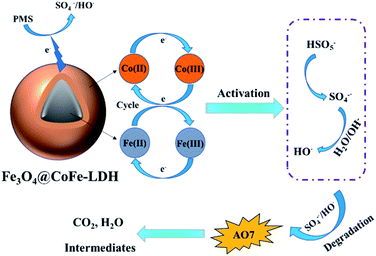 |
| | Fig. 10 The possible mechanisms of Fe3O4@CoFe-LDH activated PMS for AO7 degradation. | |
4. Conclusion
A core@shell magnetic heterogeneous catalyst Fe3O4@CoFe-LDH was successfully synthesized by one-step co-precipitation in presence of self-made Fe3O4 nanosphere, and employed to activate PMS for degradation of organic azo-dye AO7. Fe3O4@CoFe-LDH possessed a core@shell structure with a large specific surface area and well magnetic property. It was confirmed Fe3O4@CoFe-LDH possessed more excellent PMS activation capability compared to bare Fe3O4 and raw CoFe-LDH. In the presence of 0.12 mM PMS, 50 mg L−1 catalyst, pH of 6, and temperature of 298 K, 95.1% AO7 (40 mg L−1) could be degraded within 15 min by Fe3O4@CoFe-LDH/PMS system. The as-prepared magnetic nanocomposite exhibited excellent tolerance to pH (4–9) and relative activation energy (39.9 kJ mol−1). The degradation efficiency of AO7 in Fe3O4@CoFe-LDH/PMS system was more or less affected by inorganic anions and the inhibiting order of anions was HCO3− > Cl− > H2PO4− ≫ NO3−. The magnetic property of Fe3O4@CoFe-LDH could be conveniently recovered from an aqueous solution by external magnetic field for reuse. After five cycles, Fe3O4@CoFe-LDH maintained 88.7% AO7 degradation rate. Furthermore, quenching tests indicated that SO4˙ was the dominant radical in Fe3O4@CoFe-LDH/PMS. The enhanced catalytic performances were mainly attributed to the synergistic effect between core structure of Fe3O4 and active sites of CoFe-LDH, resulting rapid transformation of Co(II)/Co(III). In sum, this work provides a new discovery of the potential of magnetic LDH for PMS activation in wastewater treatment.
Conflicts of interest
The authors declare that they have no conflict of interest.
Acknowledgements
This work was supported by the National Natural Science Foundation of China (Grant No. 41907270).
References
- E. Brillas and C. A. Martínez-Huitle, Appl. Catal., B, 2015, 166–167, 603–643 CrossRef CAS
 .
. - A. A. Basaleh, M. H. Al-Malack and T. A. Saleh, J. Environ. Chem. Eng., 2021, 9, 105126 CrossRef CAS
 .
. - T. A. Saleh and I. Ali, J. Environ. Chem. Eng., 2018, 6, 5361–5368 CrossRef CAS
 .
. - M. Solis, A. Solis, H. I. Perez, N. Manjarrez and M. Flores, Process Biochem., 2012, 47, 1723–1748 CrossRef CAS
 .
. - S. O. Ganiyu, T. X. Huong Le, M. Bechelany, G. Esposito, E. D. van Hullebusch, M. A. Oturan and M. Cretin, J. Mater. Chem. A, 2017, 5, 3655–3666 RSC
 .
. - H. Liu, H. Y. Hao, J. Xing, J. J. Dong, Z. L. Zhang, Z. Y. Zheng and K. Zhao, J. Mater. Sci., 2016, 51, 5872–5879 CrossRef CAS
 .
. - Y. Y. Wang, S. R. Sun, Y. Q. Liu, Y. Z. Zhang, J. F. Xia and Q. F. Yang, J. Mater. Sci., 2020, 55, 12274–12286 CrossRef CAS
 .
. - B. Sheng, F. Yang, Y. H. Wang, Z. H. Wang, Q. Li, Y. G. Guo, X. Y. Lou and J. S. Liu, Chem. Eng. J., 2019, 375, 121989 CrossRef CAS
 .
. - T. A. Saleh, Environ. Technol. Innovation, 2020, 20, 101067 CrossRef CAS
 .
. - T. A. Saleh, Trends Environ. Anal. Chem., 2020, 28, e00101 CrossRef CAS
 .
. - Y. J. Gu, S. R. Sun, Y. Q. Liu, M. J. Dong and Q. F. Yang, ACS Omega, 2019, 4, 17672–17683 CrossRef CAS PubMed
 .
. - Z. Wu, Y. Wang, Z. Xiong, Z. Ao, S. Pu, G. Yao and B. Lai, Appl. Catal., B, 2020, 277, 119136 CrossRef CAS
 .
. - Y.-Y. Ahn, H. Bae, H.-I. Kim, S.-H. Kim, J.-H. Kim, S.-G. Lee and J. Lee, Appl. Catal., B, 2019, 241, 561–569 CrossRef CAS
 .
. - S. Z. Jian, S. R. Sun, Y. Zeng, Z. W. Liu, Y. Q. Liu, Q. F. Yang and G. H. Ma, Appl. Surf. Sci., 2020, 505, 144318 CrossRef CAS
 .
. - P. Hu and M. Long, Appl. Catal., B, 2016, 181, 103–117 CrossRef CAS
 .
. - L. Chen, D. Ding, C. Liu, H. Cai, Y. Qu, S. Yang, Y. Gao and T. Cai, Chem. Eng. J., 2018, 334, 273–284 CrossRef CAS
 .
. - A. M. Alansi, M. Al-Qunaibit, I. O. Alade, T. F. Qahtan and T. A. Saleh, J. Mol. Liq., 2018, 253, 297–304 CrossRef CAS
 .
. - A. M. Alansi, T. F. Qahtan and T. A. Saleh, Adv. Mater. Interfaces, 2021, 8, 2001463 CrossRef CAS
 .
. - J. Zhu, Z. Zhu, H. Zhang, H. Lu and Y. Qiu, RSC Adv., 2019, 9, 2284–2291 RSC
 .
. - H. Zeng, L. Deng, Z. Shi, J. Luo and J. Crittenden, J. Mater. Chem. A, 2019, 7, 342–352 RSC
 .
. - L. Yu, H. Q. Zhou, J. Y. Sun, F. Qin, D. Luo, L. X. Xie, F. Yu, J. M. Bao, Y. Li, Y. Yu, S. Chen and Z. F. Ren, Nano Energy, 2017, 41, 327–336 CrossRef CAS
 .
. - R. Guo, Y. Zhu, X. Cheng, J. Li and J. C. Crittenden, J. Hazard. Mater., 2020, 399, 122966 CrossRef CAS PubMed
 .
. - X. Zhao, C. Niu, L. Zhang, H. Guo, X. Wen, C. Liang and G. Zeng, Chemosphere, 2018, 204, 11–21 CrossRef CAS PubMed
 .
. - Q. Ma, L.-c. Nengzi, B. Li, Z. Wang, L. Liu and X. Cheng, Sep. Purif. Technol., 2020, 235, 116204 CrossRef CAS
 .
. - Y. Wang, H. Sun, H. M. Ang, M. O. Tade and S. Wang, J. Colloid Interface Sci., 2014, 433, 68–75 CrossRef CAS PubMed
 .
. - Y. Wang, H. Sun, H. M. Ang, M. O. Tadé and S. Wang, Chem. Eng. J., 2014, 245, 1–9 CrossRef CAS
 .
. - I. K. Jung, Y. Jo, S. C. Han and J. I. Yun, Sci. Total Environ., 2020, 705, 135814 CrossRef CAS PubMed
 .
. - T. Fan, D. Pan and H. Zhang, Ind. Eng. Chem. Res., 2011, 50, 9009–9018 CrossRef CAS
 .
. - W. Yang, J. Li, M. Wang, X. Sun, Y. Liu, J. Yang and D. H. L. Ng, Colloids Surf., B, 2020, 188, 110742 CrossRef CAS PubMed
 .
. - L. Jiang, J. Chen, Y. An, D. Han, S. Chang, Y. Liu and R. Yang, Sci. Total Environ., 2020, 745, 141163 CrossRef CAS PubMed
 .
. - T. A. Saleh, Environ. Sci. Pollut. Res., 2015, 22, 16721–16731 CrossRef CAS PubMed
 .
. - T. A. Saleh, J. Water Supply: Res. Technol.--AQUA, 2015, 64, 892–903 CrossRef
 .
. - X. Li, T. Hou, L. Yan, L. Shan, X. Meng and Y. Zhao, J. Hazard. Mater., 2020, 398, 122884 CrossRef CAS PubMed
 .
. - Y. X. Zhu, Y. M. Zhou, T. Zhang, M. He, Y. J. Wang, X. M. Yang and Y. Yang, Appl. Surf. Sci., 2012, 263, 132–138 CrossRef CAS
 .
. - Q. Yan, Z. Zhang, Y. Zhang, A. Umar, Z. Guo, D. O'Hare and Q. Wang, Eur. J. Inorg. Chem., 2015, 2015, 4182–4191 CrossRef CAS
 .
. - W.-h. Li, X.-p. Yue, C.-s. Guo, J.-p. Lv, S.-s. Liu, Y. Zhang and J. Xu, Appl. Surf. Sci., 2015, 335, 23–28 CrossRef CAS
 .
. - L. Li, Y. Liu, S. Zhang, M. Liang, F. Li and Y. Yuan, J. Hazard. Mater., 2020, 399, 122883 CrossRef CAS PubMed
 .
. - Q. Ye, J. Wu, P. Wu, J. Wang, W. Niu, S. Yang, M. Chen, S. Rehman and N. Zhu, Water Res., 2020, 185, 116246 CrossRef CAS PubMed
 .
. - D. Chen, X. Ma, J. Zhou, X. Chen and G. Qian, J. Hazard. Mater., 2014, 279, 476–484 CrossRef CAS PubMed
 .
. - F. Ghanbari and M. Moradi, Chem. Eng. J., 2017, 310, 41–62 CrossRef CAS
 .
. - R. Salazar, E. Brillas and I. Sires, Appl. Catal., B, 2012, 115, 107–116 CrossRef
 .
. - S. Xiao, M. Cheng, H. Zhong, Z. Liu, Y. Liu, X. Yang and Q. Liang, Chem. Eng. J., 2020, 384, 123265 CrossRef CAS
 .
. - Y. Liu, R. Luo, Y. Li, J. Qi, C. Wang, J. Li, X. Sun and L. Wang, Chem. Eng. J., 2018, 347, 731–740 CrossRef CAS
 .
. - W. Zhang, G. Tang, J. Yan, L. Zhao, X. Zhou, H. Wang, Y. Feng, Y. Guo, J. Wu, W. Chen, N. Yuan and M. Li, Appl. Surf. Sci., 2020, 509, 144886 CrossRef CAS
 .
. - Z. H. Wang, R. X. Yuan, Y. G. Guo, L. Xu and J. S. Liu, J. Hazard. Mater., 2011, 190, 1083–1087 CrossRef CAS PubMed
 .
. - F. Qi, W. Chu and B. B. Xu, Chem. Eng. J., 2014, 235, 10–18 CrossRef CAS
 .
. - S. Zilberg, A. Mizrahi, D. Meyerstein and H. Kornweitz, Phys. Chem. Chem. Phys., 2018, 20, 9429–9435 RSC
 .
. - C. Q. Tan, N. Y. Gao, D. F. Fu, J. Deng and L. Deng, Sep. Purif. Technol., 2017, 175, 47–57 CrossRef CAS
 .
. - Q. Peng, Y. Dai, K. Liu, X. Luo, D. He, X. Tang and G. Huang, J. Mater. Sci., 2020, 55, 11267–11283 CrossRef CAS
 .
. - C. You, Y. Y. Ji, Z. Liu, X. L. Xiong and X. P. Sun, ACS Sustainable Chem. Eng., 2018, 6, 1527–1531 CrossRef CAS
 .
.
Footnote |
| † Electronic supplementary information (ESI) available. See DOI: 10.1039/d1ra02973h |
|
| This journal is © The Royal Society of Chemistry 2021 |
Click here to see how this site uses Cookies. View our privacy policy here.  Open Access Article
 *b and
Chiquan He*a
![[thin space (1/6-em)]](https://www.rsc.org/images/entities/char_2009.gif) :
:![[thin space (1/6-em)]](https://www.rsc.org/images/entities/char_2009.gif) iron molar ratio of 1
iron molar ratio of 1![[thin space (1/6-em)]](https://www.rsc.org/images/entities/char_2009.gif) :
:![[thin space (1/6-em)]](https://www.rsc.org/images/entities/char_2009.gif) 1) achieved 95.1% removal rate of AO7 (40 mg L−1) within 15 min under the optimized conditions, which outperformed bare Fe3O4 and raw CoFe-LDH11. Meanwhile, Fe3O4@CoFe-LDH11 displayed good adaptability in a wide pH range from 4 to 9 and relatively low PMS activation energy (39.9 kJ mol−1). The interference tests revealed HCO3− to possess the strongest restriction effect. Only 57.7% AO7 was removed when 10 mM HCO3− was introduced, which was ascribed to HCO3− not only serving as a radical scavenger, but also increasing the pH of the system. The radical quenching tests demonstrated SO4˙− as the dominant reactive species during the catalytic reaction. Based on X-ray photoelectron spectroscopy (XPS) analysis, the core structure of Fe3O4 served as an electron donor for accelerating the cycle of Co(II)/Co(III) at the active site of the LDH outer shell. Also, Fe3O4@CoFe-LDH exhibited outstanding stability and recyclability, and maintained high degradation efficiency of AO7 even after five cycles. In sum, the proposed magnetic Fe3O4@CoFe-LDH nanocomposite has great potential for remediation of wastewater contaminated with synthetic dyes.
1) achieved 95.1% removal rate of AO7 (40 mg L−1) within 15 min under the optimized conditions, which outperformed bare Fe3O4 and raw CoFe-LDH11. Meanwhile, Fe3O4@CoFe-LDH11 displayed good adaptability in a wide pH range from 4 to 9 and relatively low PMS activation energy (39.9 kJ mol−1). The interference tests revealed HCO3− to possess the strongest restriction effect. Only 57.7% AO7 was removed when 10 mM HCO3− was introduced, which was ascribed to HCO3− not only serving as a radical scavenger, but also increasing the pH of the system. The radical quenching tests demonstrated SO4˙− as the dominant reactive species during the catalytic reaction. Based on X-ray photoelectron spectroscopy (XPS) analysis, the core structure of Fe3O4 served as an electron donor for accelerating the cycle of Co(II)/Co(III) at the active site of the LDH outer shell. Also, Fe3O4@CoFe-LDH exhibited outstanding stability and recyclability, and maintained high degradation efficiency of AO7 even after five cycles. In sum, the proposed magnetic Fe3O4@CoFe-LDH nanocomposite has great potential for remediation of wastewater contaminated with synthetic dyes.![[thin space (1/6-em)]](https://www.rsc.org/images/entities/char_2009.gif) 000), acid orange 7 (AO7, 99.0 wt%) and peroxymonosulfate (2KHSO5·KHSO4·K2SO4, 98.0 wt%) were purchased from Adamas-Beta Reagent Co., Ltd. Sodium hydroxide (NaOH, 98.0 wt%), sodium carbonate (Na2CO3, 99.8 wt%), sodium hydrogen carbonate (NaHCO3, 99.5 wt%), sodium acetate (NaAc, 99.0 wt%), and tert-butanol (TBA, 99 wt%) were purchased from Shanghai Titan Scientific Co., Ltd. Cobalt chloride hexahydrate (CoCl2·6H2O, 98.0 wt%) and sulfuric acid (H2SO4) were purchased from Sinopharm Chemical Reagent Co., Ltd. All chemicals were commercially available. Deionized (DI) water was used to prepare solutions throughout the study.
000), acid orange 7 (AO7, 99.0 wt%) and peroxymonosulfate (2KHSO5·KHSO4·K2SO4, 98.0 wt%) were purchased from Adamas-Beta Reagent Co., Ltd. Sodium hydroxide (NaOH, 98.0 wt%), sodium carbonate (Na2CO3, 99.8 wt%), sodium hydrogen carbonate (NaHCO3, 99.5 wt%), sodium acetate (NaAc, 99.0 wt%), and tert-butanol (TBA, 99 wt%) were purchased from Shanghai Titan Scientific Co., Ltd. Cobalt chloride hexahydrate (CoCl2·6H2O, 98.0 wt%) and sulfuric acid (H2SO4) were purchased from Sinopharm Chemical Reagent Co., Ltd. All chemicals were commercially available. Deionized (DI) water was used to prepare solutions throughout the study.
![[thin space (1/6-em)]](https://www.rsc.org/images/entities/char_2009.gif) :
:![[thin space (1/6-em)]](https://www.rsc.org/images/entities/char_2009.gif) 1, 2
1, 2![[thin space (1/6-em)]](https://www.rsc.org/images/entities/char_2009.gif) :
:![[thin space (1/6-em)]](https://www.rsc.org/images/entities/char_2009.gif) 1, 1
1, 1![[thin space (1/6-em)]](https://www.rsc.org/images/entities/char_2009.gif) :
:![[thin space (1/6-em)]](https://www.rsc.org/images/entities/char_2009.gif) 2, 1
2, 1![[thin space (1/6-em)]](https://www.rsc.org/images/entities/char_2009.gif) :
:![[thin space (1/6-em)]](https://www.rsc.org/images/entities/char_2009.gif) 4, total metal concentration is 10 mmol) were synthesized based on the above method, and labeled as Fe3O4@CoFe-LDH41, Fe3O4@CoFe-LDH21, Fe3O4@CoFe-LDH12 and Fe3O4@CoFe-LDH14. Bare CoFe-LDH11 was also made in the absence of Fe3O4 for the control comparison. And, the detailed information of preparation method of CoFe2O4 was shown in the ESI (Text S1).†
4, total metal concentration is 10 mmol) were synthesized based on the above method, and labeled as Fe3O4@CoFe-LDH41, Fe3O4@CoFe-LDH21, Fe3O4@CoFe-LDH12 and Fe3O4@CoFe-LDH14. Bare CoFe-LDH11 was also made in the absence of Fe3O4 for the control comparison. And, the detailed information of preparation method of CoFe2O4 was shown in the ESI (Text S1).†
![[thin space (1/6-em)]](https://www.rsc.org/images/entities/char_2009.gif) Ct/C0 = −kobst
Ct/C0 = −kobst
![[thin space (1/6-em)]](https://www.rsc.org/images/entities/char_2009.gif) :
:![[thin space (1/6-em)]](https://www.rsc.org/images/entities/char_2009.gif) 4 to 1
4 to 1![[thin space (1/6-em)]](https://www.rsc.org/images/entities/char_2009.gif) :
:![[thin space (1/6-em)]](https://www.rsc.org/images/entities/char_2009.gif) 1, the degradation efficiency of AO7 after 5 min varied from 75.9% to 91.7%. Therefore, within this range, the cobalt content played a key role in controlling the reaction rate. Further increase in cobalt content led to the kobs values of Fe3O4@CoFe-LDH11, Fe3O4@CoFe-LDH21 and Fe3O4@CoFe-LDH41 reaching 0.549 min−1, 0.373 min−1 and 0.431 min−1, respectively (Fig. S5b†). However, further raising the molar ratio of cobalt may cause excess divalent cobalt that could react with SO4˙− to generate SO42−. This, in turn, resulted in a slightly declined AO7 degradation rate.40 Hence, a Co/Fe molar ratio of 1
1, the degradation efficiency of AO7 after 5 min varied from 75.9% to 91.7%. Therefore, within this range, the cobalt content played a key role in controlling the reaction rate. Further increase in cobalt content led to the kobs values of Fe3O4@CoFe-LDH11, Fe3O4@CoFe-LDH21 and Fe3O4@CoFe-LDH41 reaching 0.549 min−1, 0.373 min−1 and 0.431 min−1, respectively (Fig. S5b†). However, further raising the molar ratio of cobalt may cause excess divalent cobalt that could react with SO4˙− to generate SO42−. This, in turn, resulted in a slightly declined AO7 degradation rate.40 Hence, a Co/Fe molar ratio of 1![[thin space (1/6-em)]](https://www.rsc.org/images/entities/char_2009.gif) :
:![[thin space (1/6-em)]](https://www.rsc.org/images/entities/char_2009.gif) 1 was selected as the optimal value for subsequent catalytic experiments.
1 was selected as the optimal value for subsequent catalytic experiments.![[thin space (1/6-em)]](https://www.rsc.org/images/entities/char_2009.gif) k = ln
k = ln![[thin space (1/6-em)]](https://www.rsc.org/images/entities/char_2009.gif) A − Ea/RT
A − Ea/RT
.
.
.
.
.
.
.
.
.
.
.
.
.
.
.
.
.
.
.
.
.
.
.
.
.
.
.
.
.
.
.
.
.
.
.
.
.
.
.
.
.
.
.
.
.
.
.
.
.
.


