 Open Access Article
Preparation and electrochemical properties of a novel porous Ti/Sn–Sb-RuOx/β-PbO2/MnO2 anode for zinc electrowinning
Buming Chenac,
Jianhua Liu *ab,
Shichuan Wang*ab,
Hui Huangac,
Yapeng Heac and
Zhongcheng Guoac
aFaculty of Metallurgical and Energy Engineering, Kunming University of Science and Technology, Kunming 650093, China. E-mail: liujianhua501050@163.com; kmustshichuanwang@163.com
bState Key Laboratory of Complex Nonferrous Metal Resources Clean Utilization, Kunming University of Science and Technology, Kunming 650093, China
cKunming Hengda Technology Co. LTD., Kunming 650106, China
First published on 26th May 2021
Abstract
MnO2 coatings prepared in a sulfate system (S-MnO2) and MnO2 prepared in a nitrate system (N-MnO2) were successfully deposited on porous Ti/Sn–Sb-RuOx/β-PbO2 substrates by electrodeposition, and their electrochemical properties were studied in detail. The bath composition plays a very important role in the MnO2 coating prepared by electrodeposition at a low current density. The results of scanning electron microscopy show that a Ti/Sn–Sb-RuOx/β-PbO2/MnO2 electrode has a rough morphology and the unit cell is very good. At the same time, the surface cracks in the S-MnO2 coating are larger than those in the N-MnO2 coating. In addition, the N-MnO2 coating is composed of a fluffy sheet-like substance. The surface morphology of the N-MnO2 coating is denser than that of the S-MnO2 coating. The S-MnO2 coating consists of irregularly stacked granular particles. Further, the main crystal phase of MnO2 is γ type, and the main valence state of MnO2 is +4. The results show that the oxygen evolution potential of the N-MnO2 electrode is 63 mV lower than that of the S-MnO2 electrode, indicating that the N-MnO2 electrode has better oxygen evolution activity and electrochemical stability, which can also be confirmed by EIS test results. Under the accelerated life test conditions, the N-MnO2 electrode has a better service life of 77 h at a current density of 1 A cm−2 in 150 g L−1 H2SO4 and 2 g L−1 Cl− solution.
1. Introduction
The oxygen evolution reaction (OER) is the primary anode reaction in the zinc electrowinning (EW) process, and the overpotential of the anode material directly determines the cell voltage and energy consumption of the process. In recent years, lead alloy and titanium-based electrode materials have been mostly used in the hydrometallurgical industry and in the EW field. Conventional lead-based anodes used in zinc EW are associated with high corrosion rates and oxygen evolution overpotential. However, both electrodes (lead and titanium) suffer from issues such as large internal resistance. In sulphate electrolyte, the active oxygen generated by the electrolysis reaction is immersed in the surface of the titanium substrate, generating passivation on the surface of the titanium substrate and forming an oxide film (i.e. TiO2). Manganese ions, which typically exist in zinc EW electrolyte, can influence anode performance, depending on their concentration and the anode material. Therefore, the authors developed a new composite anode by using MnO2 particles in a composite matrix to improve anode performance under zinc EW operating conditions.1,2 A recent report showed that MnO2 is an oxygen evolution anode that is only less active than RuO2 and IrO2.3 However, its stability is poor, and this condition is related to the nature of manganese. As a transition metal, manganese has a special d-electron shell structure.4 In accordance with Jahn–Teller theory, ions with an asymmetric d-electron shell structure deviate from normal octahedrons or regular tetrahedrons.5 Manganese oxide is a typical representative of Betolai (i.e. nonspecific) compounds, and its structure is extremely varied. The representative oxide of MnO2 is actually an oxide between MnO1.7 and MnO2. Given the special d-electron shell structure of manganese, its oxides are mostly in nonequilibrium phases, with numerous lattice defects and distortion.6 The atom at the defect, whether it is a surface or point defect, is in a high energy state, generating chemical activities in the crystal. Therefore, MnO2 is currently recognised as one of the most electrochemically active electrode materials.7 However, it exhibits the disadvantages of low processing strength and short service life.8As a new type of anode, a titanium-based MnO2 anode does not easily dissolve during the electrolysis process; it also does not pollute EW products, can produce high-purity metals and has high mechanical strength; thus, it prevents cathode–anode short circuit, corrosion resistance and low energy consumption.9 However, its conductivity and stability are not ideal, and this problem is solved by adding an intermediate layer.
Lead dioxide is widely used because of its good electrical conductivity, good mechanical properties, relatively low preparation cost, good chemical stability in acidic solutions, low oxygen evolution overpotential and relatively large specific surface area.10–12 On this basis, porous lead dioxide was prepared because of its high electrocatalytic activity.13 Simultaneously, given the unique surface morphology of porous lead dioxide, MnO2 deposited on its surface will form a partially mosaic structure, improving the binding force between the two substances and the stability of the electrode.
MnO2 electrodeposited under similar conditions from acidic solutions of manganese chloride, manganese nitrate or manganese perchlorate exhibits a clear fibrous structure. The axes of single fibres are parallel with the direction of growth. Fibrous MnO2 exhibits an excellent orientation, a high degree of crystallisation and needle-shaped crystallites. Direct current resistance in the direction parallel to the direction of growth is considerably lower than the resistance in the direction normal to the direction of growth.14
We proposed a new preparation method for MnO2 on a porous Ti/Sn–Sb-RuOx/β-PbO2 substrate by using low current density. Surface morphology and phase were investigated by comparing MnO2 electrodes prepared in two different plating baths. The composition and electrochemical properties of the electrode were investigated by using scanning electron microscopy (SEM), X-ray diffraction (XRD), X-ray photoelectron spectroscopy (XPS) and an electrochemical workstation. In addition, the stability of the electrode was studied via accelerated life testing.
2. Experiments
2.1. Preparation of electrodes
![[thin space (1/6-em)]](https://www.rsc.org/images/entities/char_2009.gif) :
:![[thin space (1/6-em)]](https://www.rsc.org/images/entities/char_2009.gif) 4
4![[thin space (1/6-em)]](https://www.rsc.org/images/entities/char_2009.gif) :
:![[thin space (1/6-em)]](https://www.rsc.org/images/entities/char_2009.gif) 5) for 3 min to remove the oxide layer and washed with DI water. Thereafter, the further cleaned titanium plates were etched in 20 wt% HCl solution at 90 °C for 120 min to form a rough surface. Finally, the pretreated titanium substrate was stored in a solution of ethanol and 2% oxalic acid at room temperature before use.
5) for 3 min to remove the oxide layer and washed with DI water. Thereafter, the further cleaned titanium plates were etched in 20 wt% HCl solution at 90 °C for 120 min to form a rough surface. Finally, the pretreated titanium substrate was stored in a solution of ethanol and 2% oxalic acid at room temperature before use.2.2. Characterization of electrodes
An electrochemical workstation (CS350, Corrtest, China) with three electrode systems was used to perform anodic polarisation, cyclic voltammetry (CV) and electrochemical impedance spectroscopy (EIS) in a synthetic electrolyte solution composed of 50 g L−1 Zn2+ and 150 g L−1 H2SO4 at 40 °C. The working electrode (WE) was the experimental samples with a working area of 1.0 cm2. The remaining areas were sealed with epoxy resin. The reference electrode (RE) was a saturated calomel electrode (SCE). The counter electrode (CE) consisted of a 6 cm2 platinum plate. The scanning rate for the anodic polarisation curve was 10 mV s−1. The frequency interval of the EIS measurements ranged from 105 Hz to 10−1 Hz, and the alternating current (AC) amplitude was 5 mV root mean squared. The applied anodic potential was 1.5 V (SCE). The impedance data were converted into Nyquist data format and then fitted into appropriate equivalent electrical.The surface morphology of the anodic oxide layer was characterised via SEM by using a Philips XL30 environmental scanning electron microscope (Holland). XPS spectra were collected from samples by using a K-Alpha™ spectrometer (Thermo Fisher Scientific Inc., USA) to analyse the chemical composition. The analysed values of the binding energy (BE) were relative to the C 1s photoelectron line (BE = 284.8 eV). The phase composition of the films was studied via XRD by using a D8 ADVANCE diffractometer (Bruker, Germany) with Cu K-alpha radiation.
The service life of the two anode coatings was evaluated in a solution containing 2 g L−1 Cl− and 150 g L−1 sulphuric acid at 25 °C with a titanium mesh as the cathode. The distance between electrodes was 20 mm, and the current density was 1 A cm−2.
3. Results and discussion
3.1. SEM analysis
Fig. 1 shows the SEM images of MnO2 prepared via electrodeposition in different plating baths. The surface of Fig. 1a is densely packed with a large number of particles, exhibiting a dense and uniform structure. A large number of fine cracks are found on the surface of Fig. 1b, and surface granular morphology is evident. Simultaneously, the surface of MnO2 prepared under both conditions has a pore-like morphology because the anode continues to evolve oxygen during the preparation of the electrode, and Mn2+ is deposited onto the surface of the electrode along the adhered oxygen bubbles. In addition, Mn2+ is deposited inside the pores because the electrode is porous. The surface morphology of the electrodes is covered to form a MnO2 coating. As shown in Fig. 1c and d, these small particles are stacked on one another to form a relatively dense structure. The surface grain bonding of Fig. 1c is tighter than that of Fig. 1d. Fig. 1e and f illustrate the structure of the reaction electrode at high magnification. The morphology of N-MnO2 under microscopic appearance is ribbonlike, layered and densely bonded. The grain size is 50–150 nm. S-MnO2 is microscopically shaped. The grains have a sharp grainy shape, which is intertwined and has many intergranular voids. Grain size is between 50 nm and 100 nm, and crystal grains are randomly stacked. The gap between crystal grains is larger, and thus, more conducive to the penetration of the electrolyte. The surface morphology of the two electrodes observed under high magnification can indicate that the electrolyte is more likely to penetrate into the S-MnO2 coating and come in contact with the substrate during the use of the electrode.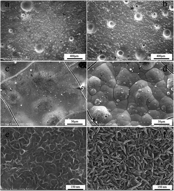 | ||
| Fig. 1 SEM images of the Ti/Sn–Sb-RuOx/β-PbO2/MnO2 coatings electrodeposited at different plating solution, (a, c, e) manganese nitrate solution, (b, d, f) manganese sulfate solution. | ||
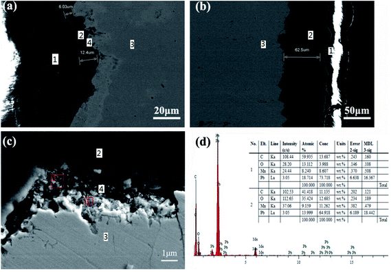
With regard to the presence of pores and cracks on the surface of the Ti/Sn–Sb-RuOx/PbO2/MnO2 coating, Fig. 2 shows a cross-sectional microscopy to evaluate the interface bonding state. Fig. 2a and c are SEM images of the N-MnO2 coating. Fig. 2b is an SEM image of the S-MnO2 coating. Fig. 2a and b show that PbO2 and MnO2 are tightly bonded, and no significant cracks are found in the MnO2 layer. The average thickness of the N-MnO2 plating layer in Fig. 2a is 9.21 μm, and the average thickness of the S-MnO2 plating layer in Fig. 2b is 62.5 μm. The high-magnification SEM image in Fig. 2c shows a significant Pb-MnOx transition layer during the electrodeposition of MnO2 in the nitric acid system. This phenomenon may be due to the reaction of PbO2 with Mn2+ in the nitric acid system to form a mixture.
3.2. XRD analysis
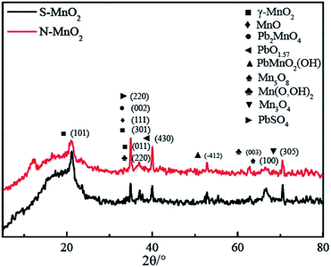
Fig. 3 shows the XRD patterns of the S-MnO2 and N-MnO2 coatings. The peak positions of the two materials are basically identical, and only a difference in peak intensity exists. The major peaks are all diffraction peaks of MnO2; however, other weaker peaks can be observed, including oxides of lead and manganese, mixed oxides of lead and manganese and trace PbSO4 (for the S-MnO2 coating). The existence of these materials indicates that the pure oxidation of Mn2+ occurs during the process of depositing MnO2 onto the surface of PbO2 and a variety of different substances are found between the interfaces.3.3. XPS analysis
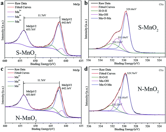
Fig. 4 presents the XPS results of the Ti/MnO2 anodes electrodeposited in different plating solutions. Fig. 4a shows the Mn2p region of the S-MnO2 spectrum. The two peaks at 653.7 eV and 642.0 eV correspond to the Mn2p3/2 and Mn2p1/2 orbitals, respectively. Fig. 4c shows the Mn2p region of the N-MnO2 spectrum at 653.8 eV and 642.1 eV. The two peaks correspond to the Mn2p3/2 and Mn2p1/2 orbitals, respectively. The binding energy of S-MnO2 and N-MnO2 in the Mn2p region is 11.7 eV, which is the peak of typical MnO2,16 indicating that +4 is the primary valence of manganese. In addition, a small amount of manganese element with +3 valence and +5 valence is present.17 The O1s spectrum of S-MnO2 is shown in Fig. 4b. The binding peaks at 529.66, 531.09 and 532.12 eV correspond to Mn–O–Mn, Mn–OH and H–O–H, respectively. The O 1s spectrum of N-MnO2 is shown in Fig. 4d. The binding peaks at 529.76, 531.01 and 532.22 eV correspond to Mn–O–Mn, Mn–OH and H–O–H, respectively. The peak binding energy of Mn–O–Mn for N-MnO2 is higher than that for S-MnO2. It has shorter Mn–Mn distances, exhibits increased tunnelling probability for N-MnO2, and consequently, increased conductivity.18 Furthermore, the peak spectrum of the two MnO2 in the O 1s region indicates that the manganese oxide layer also contains hydroxide and crystal water, which are beneficial for increasing ionic conductivity, and thus, improve the activity and utilisation of manganese oxide. The incorporation of lead with semiconducting properties affects the bonding state of Mn–O and the water of crystallisation in the MnO2 lattice, causing chemical shifts in the Mn 2p3/2 level and increasing the binding energy. That is, Mn–O ionicity increases, covalency decreases and it is difficult to reduce; thus, the N-MnO2 coating is more stable than the S-MnO2 coating.19The peak area obtained by Gaussian fitting of the peak indicates the relative content of each component. The relative percentages of different valence manganese elements are listed in Table 1.
| Manganese element | Mn(III) | Mn(IV) | Mn(V) |
|---|---|---|---|
| S-MnO2-position/eV (relative content/%) | 641.23 (10.7%) | 642.32 (80.93%) | 644.9 (8.37%) |
| N-MnO2-position/eV (relative content/%) | 641.23 (11.12%) | 642.39 (74.6%) | 644.62 (14.28%) |
From the data in Table 1, the trivalent manganese oxide content of N-MnO2 is greater than the oxide content of S-MnO2. A complex oxide with a helical structure and that lacks cations in the crystal structure is formed. Therefore, the specific surface area of the MnO2 crystal and the activity of the redox reaction are increased.18
3.4. Deposition mechanism of MnO2
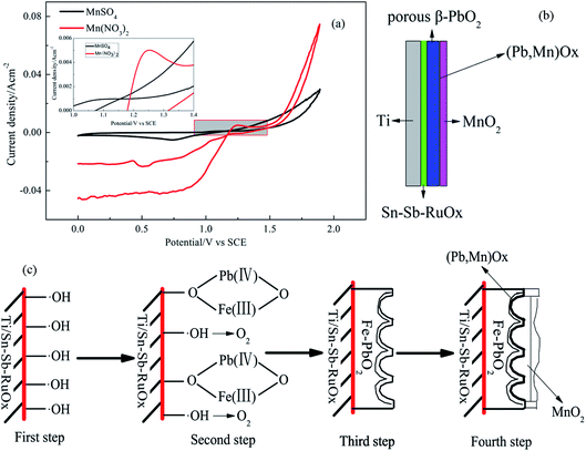
Fig. 5a shows the CV curves of the Ti/Sn–Sb-RuOx/PbO2 electrodes in the Mn(NO3)2 and MnSO4 baths at a scan rate of 5 mV s−1 at 60 °C. A potential range of 0–1.9 V (versus SCE) is used. The PbO2 electrodes exhibit an evident symmetry on the CV curve in the MnSO4 bath. An oxidation peak occurs between 1.00 V and 1.40 V. The PbO2 electrodes present an evident asymmetry on the CV curve in the Mn(NO3)2 plating solution, and a negative current value appears at 1.00–1.18 V. Then, the current rapidly rises to a positive value, and a large peak current occurs at 1.25 V. Finding that the current intensity of the oxidation peak between 1.20 V and 1.40 V in the Mn(NO3)2 plating solution is higher than that in the MnSO4 plating system is not difficult.Owen et al.20 confirmed the deposition mechanism in the sulphuric acid system as follows:
 | (1) |
| Mn2+ads → Mn3+ + e− (fast) (1.23 V vs. SHE) | (2) |
| Mn3+ + 2H2O → MnOOH + 3H+ | (3) |
| MnOOH → MnO2 + H+ + e− (slow) | (4) |
| 2H2O-4e → O2 + 4H+ (1.23 V vs. SHE) | (5) |
When the reaction in the deposition mechanism corresponds with the oxidation peak of the CV curve in the plating solution, the broadening oxidation peak within the range of 1.00–1.40 V on the curve includes reactions (2), (3) and (4). Given that OER (5) has the same standard equilibrium potential as reaction (2), the oxidation peak at 1.00–1.40 V is considered to correspond not only to the anodic electrodeposition reaction of MnO2 but also to the superposition of the OER peak. The anodic electrodeposition process of MnO2 competes with the OER within the potential range of 1.0–1.4 V.
The deposition of MnO2 onto the surface of the PbO2 electrode under acidic and high temperature conditions yields the following reaction:21
| PbO2 + Mn2+ → MnO2 + Pb2+ | (6) |
| 5PbO2 + 2Mn2+ + 4H+ → 2MnO4− + 2H2O + 5Pb2+ | (7) |
According to the reaction formula, during the deposition process, PbO2 is partially dissolved in the plating solution to form Pb2+, and Pb2+ and Mn2+ are co-deposited under electrodepositing conditions to form (Pb, Mn) oxide solid solution, which improves the stability of the electrode.22,23
However, the preceding reaction is difficult to perform in a sulphuric acid system.
| PbSO4 + 2H2O → PbO2 + SO42− + 4H+ + 2e− (1.691 V vs. SHE) | (8) |
| Mn2+ + 4H2O → MnO4− + 8H+ + 5e− (1.491 V vs. SHE) | (9) |
From the reaction formulas (8) and (9), PbO2 is a spontaneous reaction in the Mn2+-containing solution. The reaction experiences difficulty in proceeding because the product PbSO4 is a poorly soluble substance that adheres to the surface of PbO2. This condition hinders the continuation of the reaction. A possible scheme for the formation of porous PbO2 on the Ti/Sn–Sb-RuOx electrode is illustrated in Fig. 5b and c. Under high voltage and high current density, PbSO4 is converted into one part of PbO2 and MnO2 is deposited on the other part. Therefore, in the interface between MnO2 and PbO2 deposited by the sulphuric acid system, an extremely thin layer of or nearly no PbSO4 is found. The obtained MnO2 film layer is thicker. However, the dissolution of PbO2, i.e. surface MnO2 deposition, occurs during the volumetric electrodeposition of MnO2. A mutual competition results in the presence of (Pb, Mn)Ox in the interfacial layer of MnO2 and PbO2, and the deposited MnO2 film is thin.
3.5. Electrochemical examination
The electrocatalytic properties of the obtained materials are highly correlated with OER. The rate of oxygen evolution can change in accordance with nature and surface microstructure. The change in anode materials properties in relation to OER primarily depends on changes in the roughness and chemical properties of oxide surface, which, in turn, lead to a change in bond strength of the oxygen-containing species chemisorbed onto the electrode surface.24 The anodic polarisation curves of the Ti/MnO2 electrodes tested in 50 g L−1 Zn2+ and 150 g L−1 H2SO4 solution are shown in Fig. 6 for the electrodes prepared using the electrodeposition method in the manganese sulphate and manganese nitrate plating solutions, respectively. The scan rate of the anodic polarisation curve in a synthetic electrolyte at 40 °C is 5 mV s−1, and the potential range is 0–1.9 V (versus SCE), showing that both electrodes exhibit similar oxygen evolution behaviour. At a current density of 0.05 A cm−2, the oxygen evolution potentials of N-MnO2 and S-MnO2 are 1.982 V and 2.045 V, respectively. After MnO2 is deposited onto the surface of the Ti/Sn–Sb-RuOx/β-PbO2 intelayer, the oxygen evolution potential of S-MnO2 is 63 mV lower than that of N-MnO2.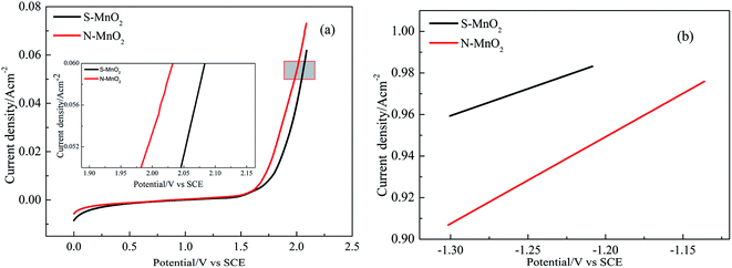 | ||
| Fig. 6 Anodic polarization curves and Tafel lines for Ti/Sn–Sb-RuOx/β-PbO2/MnO2 electrodes, (a) anodic polarization curves, (b) the fitted Tafel lines. | ||
The Tafel fitting curve of the polarisation curve is also shown in Fig. 6b. The overpotential (η) and logarithm for current density (lg![[thin space (1/6-em)]](https://www.rsc.org/images/entities/char_2009.gif) i) used for the fitted Tafel lines are obtained using eqn (10):25–27
i) used for the fitted Tafel lines are obtained using eqn (10):25–27
| η = E + 0.2415 − 1.241 − JRs | (10) |
The overpotential η and the current density i have a logarithmic relationship of the eqn (11):
η = a + b![[thin space (1/6-em)]](https://www.rsc.org/images/entities/char_2009.gif) lg lg![[thin space (1/6-em)]](https://www.rsc.org/images/entities/char_2009.gif) i i
| (11) |
In addition, the relationship between the Tafel parameters a, b and the exchange current i0 is as in eqn (12) and (13).
 | (12) |
 | (13) |
From the general formulas, i.e. eqn (10)–(13), the values of a and b and the exchange current density i0 are obtained by fitting the anodic polarisation curve with the origin 8.5, and the results are provided in Table 2. The exchange current density is the most important parameter in studying the electrocatalytic activity of the electrode in the dynamics of the electrode process. In general, the electrocatalytic activity of the electrode is higher when the exchange current density is higher.26 Therefore, from the data in Table 2, the exchange current density of S-MnO2 and N-MnO2 are 1.003 × 10⁻⁵ A cm−2 and 3.371 × 10⁻⁴ A cm−2, respectively, and the N-MnO2 electrode achieves the highest catalytic activity. Some cracks in the MnO2 coating may result in contact between the solution (50 g L−1 Zn2+ + 150 g L−1 H2SO4) and MnO2 and/or (Pb, Mn)Ox. However, given that the (Pb, Mn)Ox and MnO2 layers have highly similar oxygen evolution potential values,10 the contribution of these oxides cannot be determined.
| Samples | η/V (at 500 A m−2) | a/V | b/V | i0 (A cm−2) |
|---|---|---|---|---|
| S-MnO2 | 0.969 | 1.297 | 0.259 | 1.003 × 10⁻⁵ |
| N-MnO2 | 0.896 | 1.451 | 0.418 | 3.371 × 10⁻⁴ |
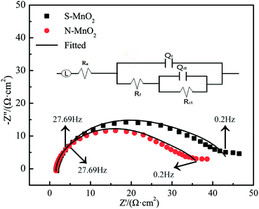
To evaluate the oxygen evolution activity of different MnO2 electrodes, EIS measurements are performed at constant potential (1.5 V) in the OER potential domain. Fig. 7 and 8 respectively show the Nyquist, Bode and phase angle plots of the S-MnO2 and N-MnO2 electrodes in the 50 g L−1 Zn2+ + 150 g L−1 H2SO4 solution.
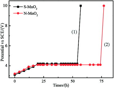 | ||
| Fig. 8 Accelerated life study of Ti/MnO2 anodes electrodeposited at different plating solution: (1) S-MnO2; (2) N-MnO2. | ||
The electrochemical impedance spectra of the two electrodes are extremely similar. They are composed of two capacitive reactance arcs, which consist of the capacitive reactance arc in the high-frequency region and the semicircular arc in the low-frequency region. However, the capacitive reactance arc size of each electrode is different. In the low-frequency region, the capacitive reactance arc is relatively large, indicating that the electrode is caused by OER occurring at the interface between the oxide coating and the solution.28 Meanwhile, the high-frequency impedance is related to the properties of the oxide film.29 A typical order of this type of magnitude inductance is 1 μH, which exhibits good agreement with that observed in the current work.30 Rs indicates the resistance of the solution, and the parallel (RctQdl) combination presents the behaviour of the interface between the oxide and the electrolyte. Meanwhile, the (RfQf) combination describes the properties of the oxide film. Other EIS parameters are listed in Table 3, where Rct and Rf are the charge transfer resistance and film resistance, respectively, and Q denotes the constant phase elements (CPEs). CPE is generally believed to be derived from the distribution of current density along the surface of the electrode as a result of surface inhomogeneity. This phenomenon can be inferred from the analogy with the behaviour of the porous electrodes.31 CPE is used to consider the phase shift impedance of the frequency between the applied AC potential and its current response. Y is defined using eqn (14):32
| Y = Y0(jω)n | (14) |
 | (15) |
| Anodes | L (μH) | Rs (Ω cm2) | Rct (Ω cm2) | ndl | Qdl (Ω−1 cm−2 Sn) | RF (Ω cm2) | nf | QF (Ω−1 cm−2 Sn) |
|---|---|---|---|---|---|---|---|---|
| S-MnO2 | 1.892 | 1.746 | 30.73 | 0.914 | 1.367 × 10⁻³ | 13.21 | 0.672 | 2.463 × 10⁻² |
| N-MnO2 | 1.907 | 1.538 | 26.94 | 0.919 | 1.034 × 10⁻³ | 8.596 | 0.749 | 3.923 × 10⁻² |
The Cdl values are obtained from the Qdl values by using eqn (15), and n denotes the degree of deviation from the perfect capacitor.35 Alves reported a new approach for the in situ characterisation of rough/porous oxide electrodes.36 On the basis of the reported procedure, the double layer capacitance, Cdl, can be used as a relative measure of the electrode surface area.
Table 3 provides the Cdl and roughness factors (RF) of the anodes. RF can be calculated using eqn (16):37
 | (16) |
| Electrodes | Cdl/(μF cm−2) | RF |
|---|---|---|
| S-MnO2 | 770.5 | 38.525 |
| N-MnO2 | 584.9 | 29.245 |
3.6. Service life evaluation
Under ambient temperature and pressure, the service life of an electrode is affected by the concentration of corrosive substances, such as acids and halogen ions, current densities and the surface characteristics of the electrode.39 As shown in Fig. 8, the trend of voltage change of the two electrodes is consistent during the accelerated life; that is, voltage rises in the beginning, remains stable and abruptly drops in the final stage, causing the electrode to fail.40 Therefore, the failure mechanism of the Ti/MnO2 electrode can be explained.41 During long-time electrolysis, MnO2 generates microcracks. Gas and solution wash these microcracks, causing the MnO2 layer to peel off from the surface of PbO2, and the potential rises to the oxygen evolution potential of PbO2. At this moment, oxygen evolution occurs in the PbO2 layer, and finally, the coating completely falls off.To accelerate the study of service life, we apply a high concentration of Cl− (2 g L−1) and high current density (1 A cm−2). The results are presented in Fig. 8. From 0 h to 20 h, the cell voltage of the S-MnO2 anode increases from 3.1 V to 4.2 V and then remains constant, indicating that the MnO2 coating is partly broken and the interlayer is exposed. By contrast, with the gradual consumption of Cl− ions, the cell voltage of the N-MnO2 anode remains stable until 74 h when both cell voltages increase linearly. Considering that the intermediate layer is basically consumed during the accelerated life test, the titanium matrix is oxidised to form a poorly conductive oxide, which increases ohmic losses. In the zinc EW industry, Cl− ions are ubiquitous in acidic zinc sulphate electrolyte solutions. Cl− ions in acidic zinc sulphate electrolyte solutions increase the corrosion rate and reduce the service life of anode plates.42 Therefore, investigating the influence of Cl− ions on the service life of the β-PbO2 electrode is meaningful from a practical perspective.
The N-MnO2 anode has a longer service life under high current density than the S-MnO2 anode. This result is further compared with the lead dioxide anodes prepared by other researchers, as shown in Table 5, where the concentration of all Cl− ions is 1 g L−1 Cl−. We conclude that the N-MnO2 anode is sufficiently stable to be used as an electrode. Many factors can affect electrode stability. Firstly, the dense and thin layer of N-MnO2 that can form on the surface of the PbO2 anode can achieve good adherence; it is also nonconductive, and thus, protects the underlying anode.43 An anode that is coated with MnO2 has a significantly lower operating voltage than typical anodes.44 However, if excessive MnO2 (for S-MnO2) forms on the anode surface, then it may not sufficiently adhere and may spall from the surface. Secondly, the crack of the N-MnO2 coating is relatively narrow, and the crack of the S-MnO2 coating is sharp and wide. Although S-MnO2 presents good spherical cell morphology and constitutes a large specific surface area, the stacking of such simple spherical particles is evidently unstable, and the contact area between these particles is small, resulting in a weak bond between the plating layer and PbO2, causing the latter to fall off easily.45 Thirdly, compared with the lead alloy anode, the MnO2 deposited on the lead alloy anode decreases the evolution rate of chlorine, and the MnO2 anode covering PbO2 has low current efficiency and high oxygen evolution efficiency, probably due to MnO2 forming a diffusional barrier to Cl− ions.46 A study on oxygen and chlorine evolution from manganese oxide-coated dimensionally stable anodes47 showed that anodic polarisation produced ‘MnO2’ results in nearly complete suppression of chlorine evolution as a result of the following: (a) an extremely low exchange current for chlorine evolution on the amorphous oxide layer and (b) the diffusion barrier provided by the oxide layer prevents access of Cl− ions to the underlying electrode surface.
| Electrodes | Solution composition | Current densities (A cm−2) | Service life (h) | Ref. |
|---|---|---|---|---|
| N-MnO2 | H2SO4 (150 g L−1) + Cl− (2 g L−1) | 1.0 | 77 | This work |
| S-MnO2 | H2SO4 (150 g L−1) + Cl− (2 g L−1) | 1.0 | 57 | This work |
| Ti/Sn–Sb–Ru/β-PbO2 | H2SO4 (150 g L−1)+ Cl− (2 g L−1) | 1.0 | 68 | 48 |
| Ti–Sn/Sb/RuO2-β-PbO2 | H2SO4 (0.5 M) | 4.0 | 48 | 49 |
| Ti/Sb–SnO2/β-PbO2 | H2SO4 (1 M) | 1.0 | 23 | 50 |
| Ti/Sb–SnO2/β-PbO2-Ce | H2SO4 (1 M) | 1.0 | 45 | 50 |
| Ti/Sb–SnO2/β-PbO2-Nd | H2SO4 (1 M) | 1.0 | 48 | 50 |
| Ti/Sb–SnO2/β-PbO2-Gd | H2SO4 (1 M) | 1.0 | 28 | 50 |
| Ti/Sb–SnO2/β-PbO2-Sm | H2SO4 (1 M) | 1.0 | 37 | 50 |
| Ti/SnO2–Sb2O3/PbO2 | H2SO4 (1 M) | 1.0 | 65 | 51 |
| Ti/SnO2–Sb2O3/MnO2 | H2SO4 (1 M) | 1.0 | 31 | 51 |
4. Conclusion
MnO2 coatings were successfully prepared on porous Ti/Sn–Sb-RuOx/β-PbO2 substrates by electrodeposition in sulfate system and nitrate system using a low current density. The important conclusion is that the composition of the electrodeposition solution may cause a significant change in the deposition mechanism during the MnO2 electrodeposition process, thereby changing the thickness of the deposited layer. SEM results show that Ti/MnO2 has a rough morphology and particle accumulation is very obvious. The morphology of N-MnO2 under microscopic appearance is microscopically shaped, layered, and densely bonded. The grain size is 50–150 nm. S-MnO2 is a ribbon-like. The surface of N-MnO2 is more uniform than S-MnO2. The main crystal phase of MnO2 is γ type, and the main valence of MnO2 is +4 valence. In addition, a small amount of Mn element with +3 valence and +5 valence is present by XPS analysis.The oxygen evolution potential of N-MnO2 at 0.05 A cm−2 is 63 mV lower than that of S-MnO2, indicating that N-MnO2 has better oxygen evolution electrocatalytic activity, which can also be confirmed by EIS test results. The embedded structure between porous Ti/Sn–Sb-RuOx/β-PbO2 substrate and MnO2 coating can increase the stability of Ti/MnO2 electrode. The stability of N-MnO2 is 77 h in a solution with 2 g L−1 Cl− and 150 g L−1 H2SO4 at 25 °C under 1 A cm−2, which is more stable than the S-MnO2.
Conflicts of interest
There are no conflicts to declare.Acknowledgements
This research is supported by Yunnan Fundamental Research Projects (grant No. 140520210048), the Natural Science Foundation of China (Project No. 51564029 and No. 51504111 and No. 51874154), the Technology Innovation Talents Project of Yunnan Province (No. 2019HB111), the construction of high-level talents of Kunming University of Science and Technology (KKKP201763019), and Research on Microwave Method in Carbon Fiber Preparation (KKK0201863053).References
- M. Minakshi, D. Mitchell and M. L. Carter, et al., Microstructural and spectroscopic investigations into the effect of CeO2 additions on the performance of a MnO2 aqueous rechargeable battery, Electrochim. Acta, 2009, 54, 3244–3249 CrossRef CAS.
- M. Minakshi, D. Mitchell and K. Prince, Incorporation of TiB2 additive into MnO2 cathode and its influence on rechargeability in an aqueous battery system, Solid State Ionics, 2008, 179, 355–361 CrossRef CAS.
- Y. Q. Wang, B. Gu, W. L. Xu and L. D. Lu, Effects of Preparation Conditions of MnOx Coatings on Characteristics of Ti/SnO2 + Sb2O3/MnOx Anodes, J. Inorg. Mater., 2006, 21, 1362–1366 CAS.
- A. Yusuf, C. Snape, J. He, H. Xu and S. Behera, Advances on transition metal oxides catalysts for formaldehyde oxidation: A review, Catal. Rev.: Sci. Eng., 2017, 59(3), 189–233 CrossRef CAS.
- M. M. Thackeray, Manganese oxides for lithium batteries, Prog. Solid State Chem., 1997, 25(1–2), 1–71 CrossRef CAS.
- Y. H. Shi, H. M. Meng and D. B. Sun, Progress of Ti based base metal oxide coating anode, J. Funct. Mater., 2007, 38, 2696–2699 Search PubMed.
- L. Mao, D. Zhang, T. Sotomura, K. N. Mechanisti, N. Koshiba and T. Ohsaka, study of the reduction of oxygen in air electrode with manganese oxides as electrocatalysts, Electrochim. Acta, 2003, 48, 1015–1021 CrossRef CAS.
- Y. Q. Lai, Y. Li, L. X. Jiang, X. J. Lv, J. Li and Y. X. Liu, Electrochemical performance of a Pb/Pb-MnO2 composite anode in sulfuric acid solution containing Mn2+, Hydrometallurgy, 2012, 115–116, 64–70 CrossRef CAS.
- E. Preisler, Material problems encountered in anodic MnO2 deposition, J. Appl. Electrochem., 1989, 19, 559–565 CrossRef CAS.
- H. T. Yang, B. M. Chen and H. R. Liu, Effects of manganese nitrate concentration on the performance of analuminum substrate β-PbO2-MnO2-WC-ZrO2 composite electrode material, Int. J. Hydrogen Energy, 2014, 39, 3087–3099 CrossRef CAS.
- M. Panizza, I. Sirés and G. Cerisola, Anodic oxidation of mecoprop herbicide at lead dioxide, J. Appl. Electrochem., 2008, 38, 923–929 CrossRef CAS.
- L. Chang, Y. Zhou, X. Duan, W. Liu and D. Xu, Preparation and characterization of carbon nanotube and Bi co-doped PbO2 electrode, J. Taiwan Inst. Chem. Eng., 2014, 45, 1338–1346 CrossRef CAS.
- B. M. Chen, S. C. Wang, J. H. Liu, H. Huang, C. Dong, Y. He, W. Yan, Z. Guo, R. Xu and H. Yang, Corrosion resistance mechanism of a novel porous Ti/Sn-Sb-RuOx/β-PbO2 anode for zinc electrowinning, Corros. Sci., 2018, 144, 136–144 CrossRef CAS.
- E. Preisler, Electrodeposited manganese dioxide with preferred crystal growth, J. Appl. Electrochem., 1976, 6, 301–310 CrossRef CAS.
- L. Li, Z. Huang, X. Fan, Z. Zhang, R. Dou, S. Wen, Y. Chen, Y. Chen and Y. Hu, Preparation and Characterization of a Pd modified Ti/SnO2-Sb anode and its electrochemical degradation of Ni-EDTA, Electrochim. Acta, 2017, 231, 354–362 CrossRef CAS.
- X. Y. Lang, A. Hirata, T. Fujita and M. W. Chen, Nanoporous metal/oxide hybrid electrodes for electrochemical supercapacitors, Nat. Nanotechnol., 2011, 6, 232–236 CrossRef CAS PubMed.
- M. M. Sundaram, A. Biswal, D. Mitchell, R. Jones and C. Fernandez, Correlation among physical and electrochemical behaviour of nanostructured electrolytic manganese dioxide from leach liquor and synthetic for aqueous asymmetric capacitor, Phys. Chem. Chem. Phys., 2016, 18, 4711–4720 RSC.
- E. Preisler, Semiconductor properties of manganese dioxide, J. Appl. Electrochem., 1976, 6, 311–320 CrossRef CAS.
- H. J. Yao, X. M. Liu and X. G. Zhang, Nanophase PbTiO3 modified MnO2 electrode, Chin. J. Appl. Chem., 2003, 20, 336–340 CAS.
- M. P. Owen, G. A. Lawrance and S. W. Donne, An electrochemical quartz crystal microbalance study into the deposition of manganese dioxide, Electrochim. Acta, 2007, 52, 4630–4639 CrossRef CAS.
- Y. M. Yang and D. J. Yan, Exploration for the trends of the reaction of PbO2 and Mn2+, Nat. Sci., 2008, 29, 403–408 Search PubMed.
- X. H. Zheng, M. M. Dai and G. R. Chen, The Anodic Behaviour of MnO2 and PbO2 Electrode Prepared by Simultaneous Electrodeposition, Nat. Sci., 1998, 14, 62–65 CAS.
- J. Wang, R. D. Xu and B. H. Yu, Investigation on Electrochemical Behavior of PbO2 and MnO2 Co-deposition, Mater. Rep., 2017, 31, 35–40 CrossRef.
- O. Shmychkova, T. Luk'yanenko, A. Velichenko, L. Meda and R. Amadelli, Bi-doped PbO2 anodes: Electrodeposition and physico-chemical properties, Electrochim. Acta, 2013, 111, 332–338 CrossRef CAS.
- H. Yang, B. Chen, Z. Guo, H. Liu, Y. Zhang, H. Huang, R. Xu and R. Fu, Effects of current density on preparation and performance of Al/conductive coating/a-PbO2-CeO2-TiO2/β-PbO2-MnO2-WC-ZrO2 composite electrode materials, Trans. Nonferrous Met. Soc. China, 2014, 24, 3394–3404 CrossRef CAS.
- Y. Lai, Y. Li, L. Jiang, W. Xu, X. Lv, J. Li and Y. Liu, Electrochemical behaviors of co-deposited Pb/Pb–MnO2, composite anode in sulfuric acid solution-Tafel and EIS investigations, J. Electroanal. Chem., 2012, 671, 16–23 CrossRef CAS.
- H. Ning, Y. Xin and L. Xu, Properties of IrO2-Ta2O5 Coated Titanium Anodes Modified with Graphene, Rare Met. Mater. Eng., 2016, 45, 946–951 CAS.
- Z. G. Ye, H. Y. Liu, X. L. Zhou, X. Z. Hua and X. Y. Peng, Effect of cooling mode on electrocatalytic activity and stability of Ti/IrO2 + MnO2 anodes, J. Funct. Mater., 2011, 42, 264–268 CAS.
- L. K. Xu and J. D. Scantlebury, A study on the deactivation of an IrO2–Ta2O5 coated titanium anode, Corros. Sci., 2003, 45, 2729–2740 CrossRef CAS.
- A. Biswal, P. K. Panda and A. N. Acharya, et al., Role of Additives in Electrochemical Deposition of Ternary Metal Oxide Microspheres for Supercapacitor Applications, ACS Omega, 2020, 5(7), 3405–3417 CrossRef CAS PubMed.
- G. J. Brug, A. L. G. van den Eeden, M. Sluyters-Rehbach and J. H. Sluyters, The analysis of electrode impedances complicated by the presence of a constant phase element, J. Electrochem. Soc., 1984, 176, 275–295 CAS.
- Y. B. Hu, C. F. Dong, M. Sun, K. Xiao, P. Zhong and X. G. Li, Effects of solution pH and Cl− on electrochemical behaviour of an Aermet100 ultra-high strength steel in acidic environments, Corros. Sci., 2011, 53, 4159–4165 CrossRef CAS.
- H. T. Yang, B. M. Chen, Z. C. Guo, H. Huang, R. D. Xu and R. C. Fu, Effects of current density on preparation and performance of Al/conductive coating/α-PbO2-CeO2-TiO2/β-PbO2-MnO2-WC-ZrO2 composite electrode materials, Trans. Nonferrous Met. Soc. China, 2014, 24, 3394–3404 CrossRef CAS.
- Z. Yan, Y. Zhao, Z. Zhang, G. Li, H. Li, J. S. Wang, Z. Q. Feng, M. Q. Tang, X. J. Yuan, R. Z. Zhang and Y. Y. Du, A study on the performance of IrO2–Ta2O5 coated anodes with surface treated Ti substrates, Electrochim. Acta, 2015, 157, 345–350 CrossRef CAS.
- V. Alves, L. Silva and J. Boodts, Surface characterisation of IrO2/TiO2/CeO2 oxide electrodes and Faradaic impedance investigation of the oxygen evolution reaction from alkaline solution, Electrochim. Acta, 1998, 44, 1525–1534 CrossRef CAS.
- V. A. Alves, L. A. D. Silva and J. F. C. Boodts, Surface characterisation of IrO2/TiO2/CeO2 oxide electrodes and faradaic impedance investigation of the oxygen evolution reaction from alkaline solution, Electrochim. Acta, 1998, 44, 1525–1534 CrossRef CAS.
- R. De Levie, On porous electrodes in electrolyte solutions: I. Capacitance effects, Electrochim. Acta, 1963, 8, 751–780 CrossRef.
- U. Casellato, S. Cattarin and M. Musiani, Preparation of porous PbO2 electrodes by electrochemical deposition of composites, Electrochim. Acta, 2000, 48, 3991–3998 CrossRef.
- X. Chen and G. Chen, Stable Ti/RuO2-Sb2O5-SnO2 electrodes for O2 evolution, Electrochim. Acta, 2005, 50, 4155–4159 CrossRef CAS.
- H. S. Kong, Research of some fundamental problems on stability of titanium substrate lead dioxide electrodes (Ti/PbO2), Doctoral Dissertation of Jilin University, 2013, pp. 32–33 Search PubMed.
- Z. F. Chen and H. Y. Jiang, The effect of electrodeposition conditions of manganese dioxide and heat treatment of PbO2-Ti/MnO2 electrode on its catalytic and lifetime, J. Cent.-South Inst. Min. Metall., 1991, 22, 207–214 CAS.
- H. T. Yang, Z. C. Guo, B. M. Chen, H. R. Liu, Y. C. Zhang, H. Huang, X. L. Li, R. C. Fu and R. D. Xu, Electrochemical behavior of rolled Pb–0.8%Ag anodes in an acidic zinc sulfate electrolyte solution containing Cl− ions, Hydrometallurgy, 2014, 147–148, 148–156 CrossRef CAS.
- M. Tunnicliffe, F. Mohammadi and A. Alfantazi, Polarization behaviour of leadsilver anodes in zinc electrowinning electrolytes, J. Electrochem. Soc., 2012, 159, C170–C180 CrossRef CAS.
- G. Eggett and D. Naden, Developments in anodes for pure copper electrowinning from solvent extraction produced electrolytes, Hydrometallurgy, 1975, 1, 123–137 CrossRef CAS.
- K. N. Cheng, Metal anodes, Shanghai, East China Normal University Press, 1989 Search PubMed.
- G. H. Kelsall, E. Guerra, G. Li and M. Bestetti, Effects of manganese (II) and chloride ions in zinc electrowinning reactors, Electrochem. Soc., Proc., 2000, 14, 350–361 Search PubMed.
- J. E. Bennett, Electrodes for generation of hydrogen and oxygen from seawater, Int. J. Hydrogen Energy, 1980, 5, 401–408 CrossRef CAS.
- S. C. Wang, S. Chen and B. M. Chen, Effect of current densities on the microstructure and electrochemical behavior of the porous β-PbO2 electrode, Mater. Sci. Forum, 2019, 956, 21–34 Search PubMed.
- Y. Zheng, W. Su, S. Chen, X. Wu and X. Chen, Ti/SnO2–Sb2O5–RuO2/α-PbO2/β-PbO2 electrodes for pollutants degradation, Chem. Eng. J., 2011, 174, 304–309 CrossRef CAS.
- W. Yang, H. Wang and F. Fu, Preparation and performance of Ti/Sb-SnO2/β-PbO2 electrode modified with rare earth, Rare Met. Mater. Eng., 2010, 39, 1215–1218 CAS.
- L. Zhou and S. H. Shi, Preparation of Ti-based metal oxide electrode and its characteristics, Environ. Prot. Chem. Ind., 2014, 34, 84–89 CAS.
| This journal is © The Royal Society of Chemistry 2021 |

