 Open Access Article
Novel construction of carbon nanofiber/CuCrO2 composite for selective determination of 4-nitrophenol in environmental samples and for supercapacitor application†
Subramanian Sakthinathan*a,
Ramachandran Rajakumaranb,
Arjunan Karthi Keyana,
Chung-Lun Yua,
Chia-Fang Wua,
Sivaramakrishnan Vinothinic,
Shen-Ming Chenb and
Te-Wei Chiu *a
*a
aDepartment of Materials and Mineral Resources Engineering, National Taipei University of Technology, No. 1, Section 3, Chung-Hsiao East Road, Taipei 106, Taiwan. E-mail: sakthinathan1988@gmail.com; tewei@ntut.edu.tw
bDepartment of Chemical Engineering and Biotechnology, National Taipei University of Technology, No. 1, Section 3, Chung-Hsiao East Road, Taipei 106, Taiwan
cDepartment of Computer Science and Information Engineering, National Taipei University of Technology, No. 1, Section 3, Chung-Hsiao East Road, Taipei 106, Taiwan
First published on 28th April 2021
Abstract
A simple hydrothermal process has been used to prepare a carbon nanofiber/copper chromium dioxide (CNF/CuCrO2) composite for the selective detection of 4-nitrophenol (4-NP) and supercapacitor applications. The electrochemical sensor was developed with a glassy carbon electrode (GCE) modified with the CNF/CuCrO2 composite by the drop-casting method. The structural formation of the prepared materials was confirmed by infrared spectroscopy, electrochemical impedance spectroscopy, Raman spectroscopy, scanning electron microscopy, X-ray diffraction, and transmission electron microscopy. To investigate the electrochemical efficiency of the electrode, various electroanalytical techniques, namely, differential pulse voltammetry (DPV), cyclic voltammetry (CV) and galvanostatic charge–discharge tests, were employed. The GCE/CNF/CuCrO2 modified electrode exhibited excellent electrocatalytic behavior for the detection of 4-NP under optimized conditions with a low detection limit (0.022 μM), long linear response range of 0.1–150 μM, and high sensitivity (20.02 μA μM−1 cm−2). The modified electrode was used for the detection of 4-NP in real samples with satisfactory results. In addition, the GCE/CNF/CuCrO2 electrode has advantages such as stability, reproducibility, repeatability, reliability, low cost, and practical application. The CNF/CuCrO2 composite coated Ni-foam electrodes also exhibited excellent supercapacitor efficiency, with a high specific capacitance of up to 159 F g−1 at a current density of 5 A g−1 and outstanding cycling stability. Hence, the CNF/CuCrO2 composite is a suitable material for 4-NP sensors and energy storage applications.
1. Introduction
The accurate detection of nitroaromatic compounds such as nitrotoluene, nitrobenzene, and nitrophenol in natural water sources is important for environmental safety because they result from a broad range of activities.1,2,18 Especially, 4-nitrophenol (4-NP) is extensively used as an intermediate in the production of pesticides, pharmaceuticals, dyestuffs, leather fungicide, analgesics, and acid–base indicators. It can cause serious adverse effects due to its toxicity and persistence, and it is considered a major hazardous pollutant in the environmental ecosystem.3 It is a bio-refractory organic compound that is anthropogenic, acidic, inhibitory, and toxic. The detoxification of water contaminated with 4-NP is extremely difficult due to its high chemical stability and resistance to microbial degradation.3,4 Moreover, 4-NP can enter the environment during its production and application in industry and agriculture.5 It is toxic to plants, sea animals, and mammals, even in very low concentrations, due to its high solubility and low degradability.5,18 For these reasons, 4-NP has been included in environmental legislation because it is a teratogen and carcinogen, and it induces mutagenic activity in humans.6,7,42 For example, 4-NP is one of the top classified environmental toxins in the United States Environmental Protection Agency (USEPA) due to its persistence and toxicity.8,9 Moreover, brief exposure to inhalation of 4-NP can induce headaches, fatigue, vomiting, and cyanosis in humans. In addition, 4-NP is considered a dangerous food cycle pollutant that appears to remain in grains, fruits, vegetables, or water supplies when it is a component of fertilizers or pesticides.10–12 Therefore, the preparation of a quickly responsive, selective, and low-cost technique for the identification of 4-NP in environmental samples for food safety and environmental safety is essential.13During the last few years, numerous analysis methods have been used for the identification of 4-NP, some examples being gas chromatography, spectrofluorometry, capillary zone electrophoresis, spectrophotometry, enzyme-linked immunosorbent assay, and high-performance liquid chromatography.14–16 However, these above-mentioned methods require expensive apparatus, long analysis times, and tedious sample pretreatment.17 As a result, there is high demand for a cost-effective detection method for 4-NP that requires little instrumentation, is easy to operate and rapid, and has high sensitivity and selectivity.18 Electrochemical detection is considered as a possible approach because of its high sensitivity, simplicity, fast analysis, real-time monitoring, ease of miniaturization, rapidity, and low cost. In addition, electrodes are easy and inexpensive to fabricate, and they have excellent reproducibility and high sensitivity in electrochemical detection.19 Consequently, the electrode material is the main component for the electrochemical detection of 4-NP.20 An unmodified GCE shows poor electrocatalytic activity such as sensitivity and selectivity for 4-NP detection. Therefore, chemically modified electrodes are established in 4-NP sensing to resolve the problems of the unmodified electrode. Modification of the working surface of the electrode can boost the efficiency of electrochemical sensors. A broad range of resources, including inorganic, organic, and polymeric molecules, as well as metal nanoparticles, have been used to modify electrodes to enhance selectivity. However, no studies on determination of 4-NP by using an inorganic complex fabricated GCE electrode have been reported to date.21–23 In recent years, delafossite structured composites have been used extensively for modified electrodes to prepare reliable electrochemical sensors.
Transparent conducting oxides (TCOs) are used in transparent electrodes, flat panel displays, optoelectronic devices, and transparent conducting film. In 1997, Kawazoe et al. stated that the ABO2 structured delafossite oxides are stable p-type broadband transparent semiconductors, where A has a triangular pattern and BO2 is an octahedral flattened structure.24,25 In addition, Cu delafossite compounds (CuIMIIIO2 (M = Co, In, B, Al, Cr, Ga)) have been used in electronic applications due to their low-lying valence band, simple preparation and high hole mobility.
In particular, CuCrO2 has properties suitable for p-type TCO, such as high optical transparency because of its direct optical bandgap (3.3 eV) and low valence band edge.26 In p-type CuCrO2, the Cu vacancy is an internal predominant defect, so holes notably exist in the Cu 3d-orbital. Therefore, CuCrO2 materials can be considered as sensor electrode materials of outstanding quality with low working potential.27,28 However, CuCrO2 has some limits in sensor applications due to its low stability and the limited surface area of the electrode surface. To reduce these limits, different approaches or modifications (covalent or non-covalent) of CuCrO2 with other stable carbon materials have been used to increase the electrocatalytic properties of CuCrO2.29,30
In materials science, carbon nanofibers (CNF) have received notable attention for the application in electroanalysis, electrochemical capacitors, dye-sensitized solar cells, Li-ion batteries, transparent conducting electrodes, nanodevices, and antimicrobial agents.31,32 In addition, CNF are biocompatible, and they have a large surface area (448 m2 g−1), excellent electrical conductivity, and chemical and thermal stability. In addition, CNF have cylindrical structures with graphene sheet stacking configurations such as herringbone, platelet stacking, and ribbon. The diameter sizes of CNF vary from a few tens of nanometers to many hundreds of nanometers.33 CNF have more edges on the outer wall, which may facilitate the higher electron transfer properties, and the whole surface area can be activated electrochemically without damage to the structural integrity.34,35 Therefore, CNF are suitable for use as an electrode material with CuCrO2 in electrochemical sensors because of the specific properties described above.36
Renewable and alternative energy sources have become a great challenge due to the enormous global consumption of energy and climate change. In various energy storage systems, batteries and electrochemical capacitors play major roles in electrical energy storage.37 Supercapacitors are a special class of energy storage devices with high voltage, long cycle life, and high-power capacity, as well as good stability, higher specific capacitance rates, high power densities, fast charge–discharge rates, and high coulombic efficiency.38 They are used in a variety of practical applications, such as electronic devices, electric vehicles, and other storage systems for renewable energy. Supercapacitors not only retain energy but also release stored energy within a short period. The essential elements of a high-performance supercapacitor are maximum power density, fast charge–discharge, and high stability.39 Supercapacitors can be divided into two classifications, namely, electric double-layer capacitors (EDLCs) and pseudocapacitors, depending on the efficiency of energy storage. In addition, pseudocapacitors and EDLCs have a low specific capacitance for redox reactions, electrosorption, and intercalation processes. As a pseudocapacitor electrode for enhancing capacitance, many materials with high surface areas and redox activity have been used. For example, CNTs, graphene, carbon nanofibers, transition metal oxides, and conductive polymers have exhibited good performance for supercapacitor electrode preparation.40,41
Metal oxide nanocomposites are widely used as a significant component for improving the selectivity and sensitivity of working electrodes in electrochemical methods. In addition, metal oxides are notable for their simplicity and ease of fabrication, sensitivity, wide surface area, and high catalytic activity.42 In the present study, a sensor electrode was modified with CNF/CuCrO2 composite prepared by hydrothermal methods. The CuCrO2 was evenly distributed on the surface of the CNF due to the non-covalent interaction between the CNF and CuCrO2 to form a new type of nanocomposite for 4-NP detection and supercapacitor applications. As CNF have easily accessible surface areas, this property was used to immobilize the CuCrO2 complexes on the electrode surface and increase the electron transfer on the surface of the electrode. The GCE/CNF/CuCrO2 electrode demonstrated excellent electrochemical efficiency with a low detection limit, fast response, excellent reproducibility, and simplicity for the detection of 4-NP. In addition, the highly active CNF/CuCrO2 composite coated Ni foil electrode showed a higher specific capacitance and excellent cycling stability during the supercapacitor performance. From these studies, we found that the CNF/CuCrO2 composite has excellent bifunctional activity for electroanalytical and capacitance performance.
2. Materials and methods
Chromium nitrate, copper nitrate, carbon nanofiber, glycine, sodium acetate, ethanol, acetic acid, hydrochloric acid, polyvinylidene difluoride, N-methyl pyrrolidinone, potassium hydroxide, sulfuric acid, sodium phosphate dibasic, and dihydrogen sodium phosphate were purchased from Sigma Aldrich, Taiwan. The dihydrogen sodium phosphate (NaH2PO4) and disodium hydrogen phosphate (Na2HPO4) were used for preparing the phosphate buffer solution (PBS). The CNF/CuCrO2 composite was studied by different physicochemical characterization techniques. The phase structure was identified by X-ray diffraction (XRD, D2 Phaser, Bruker) with CuKα radiation (λ = 1.540 Å). High-resolution transmission electron microscopy (HR-TEM) and field emission scanning electron microscopy were used for the surface morphology analysis.A scanning transmission electron microscope (STEM, JEM-2100F) with energy dispersive X-ray (EDS) spectrum analysis validated the elemental distribution. The electrochemical sensor performance of the GCE/CNF/CuCrO2 modified electrode was studied by cyclic voltammetry (CV) and differential pulse voltammetry (DPV). All the electrochemical experiments were measured using a CHI 210 electrochemical workstation (CH Instruments Co., Austin, TX, USA). For voltammetry tests, a three-electrode device, with Ag/AgCl electrode as a reference electrode, GCE as the working electrode, and platinum wire as an auxiliary electrode, was used. All the electrochemical studies were performed at room temperature, and the pH was determined by Suntex pH meter (SP-2100).
2.1 Preparation of GCE/CNF/CuCrO2 electrode
Chromium nitrate, copper nitrate, and glycine were used as starting reagents for the preparation of CuCrO2. The glycine to metal nitrate molar ratio was set at 1.5. To obtain transparent solutions, the necessary quantities of copper nitrate (2416 g), chromium nitrate (4 g), and glycine (1125 g) were dissolved in distilled water. After stirring at 80 °C for 2 h, the obtained solution was heated to 100 °C and dried for 24 h to obtain a transparent substance. This transparent glass material was then heated to about 300 °C in a beaker and spontaneously ignited to yield a gray CuCrO2 powder mass.25,26First, the obtained CuCrO2 and CNF (mass ratio of 4![[thin space (1/6-em)]](https://www.rsc.org/images/entities/char_2009.gif) :
:![[thin space (1/6-em)]](https://www.rsc.org/images/entities/char_2009.gif) 1) were placed in 15 mL of deionized water. Then a few drops of NaOH (0.5 mol) solution were added and the solution was stirred until the pH reached 10. The obtained material was poured into a Teflon-lined autoclave (20 mL) and heated for 12 h at 180 °C before being cooled to laboratory temperature. These acquired products were gathered many times with ethanol and water. After that, the collected materials were dried at 80 °C for 10 h to obtain the composite of CNF/CuCrO2.
1) were placed in 15 mL of deionized water. Then a few drops of NaOH (0.5 mol) solution were added and the solution was stirred until the pH reached 10. The obtained material was poured into a Teflon-lined autoclave (20 mL) and heated for 12 h at 180 °C before being cooled to laboratory temperature. These acquired products were gathered many times with ethanol and water. After that, the collected materials were dried at 80 °C for 10 h to obtain the composite of CNF/CuCrO2.
2.2 Preparation of the GCE/CNF/CuCrO2 electrode for the 4-NP sensor
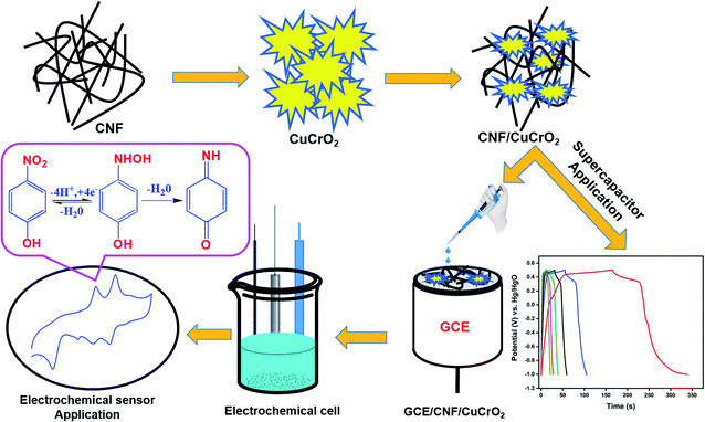
To fabricate the electrode, bare GCE was polished with alumina slurry (0.05 μm) with a polishing kit until a mirror-like surface emerged. After that, the polished bare GCE was gently washed and dried with ethanol and distilled water at room temperature. In addition, the CNF/CuCrO2 (5 mg) composite was dispersed in 1 mL of water–methanol solution by ultrasonic irradiation for 20 minutes to obtain a homogenous CNF/CuCrO2 suspension. After that, 8 μL of the prepared CNF/CuCrO2 composite solution was drop-cast on the pre-cleaned GCE electrode. The prepared GCE/CNF/CuCrO2 electrode was dried and applied for 4-NP sensor studies (Scheme 1).2.3 Supercapacitor electrode preparation
The supercapacitor working electrode was prepared as follows. The synthesized CNF/CuCrO2 composite material, graphite, and the binder polyvinylidene difluoride (PVDF) were combined with N-methyl pyrrolidinone to form slurry. After that, 20 μL of the prepared slurry was coated by the drop-casting method on the 1 × 1 cm2 area of the Ni foil electrode and dried for 6 h at 60 °C. The mass loading level of the CNF/CuCrO2 composite on the Ni foil was 1 mg cm−2.Before the electrochemical analysis, the prepared Ni foam electrode was submersed in a 1.0 M KOH electrolyte solution for a few hours. Finally, in a three-electrode cell system with a potential range of 0–1.5 V and 1.0 M KOH aqueous electrolyte solution, the electrochemical behavior of the electrodes was investigated. Ni foam-coated CNF/CuCrO2 materials were used as the working electrode, Ag/AgCl as the reference electrode, and platinum (Pt) wire as the counter electrode. The electrochemical properties of the electrodes were studied by cyclic voltammetry (CV) and galvanostatic charge–discharge (GCD) methods.
3. Results and discussion
3.1 Characterization of the prepared materials
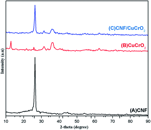
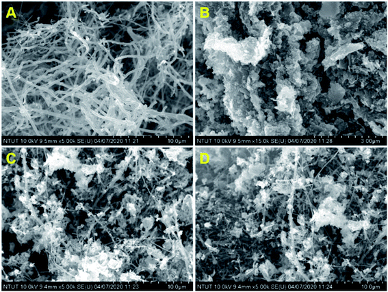
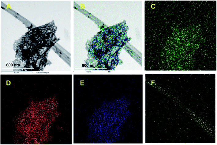
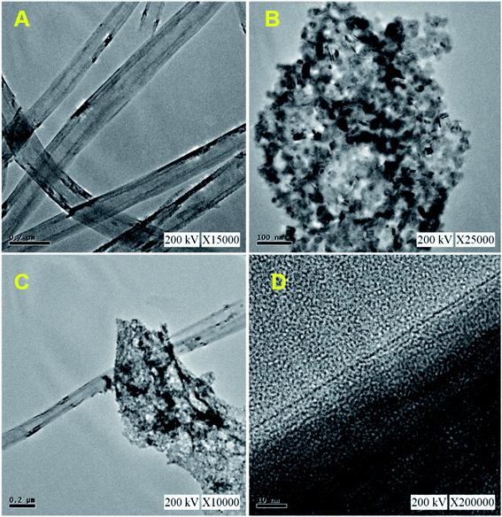
Fig. 1 shows the XRD patterns of pristine (A) CNF, (B) CuCrO2, and (C) CNF/CuCrO2 composites. The XRD spectrum of CNF exhibited a broad diffraction peak at 2θ = 25.3°, which corresponds to the (002) plane of amorphous natural hexagonal graphitic carbon. The reflection spectra of CuCrO2 nanoparticles were obtained at the 2θ values of 30.42, 35.21, 35.45, 41.88, 48.85, 54.92, 61.38, 66.62, 72.54, and 73.49, corresponding to the (006), (101), (012), (104), (009), (018), (110), (0012), (116), and (202) planes of the hexagonal crystal structure of CuCrO2 (JCPDS no: 740983). This was in concordance with previously reported CuCrO2 diffraction results. The XRD pattern of the CNF/CuCrO2 composite presented reflections corresponding to the CNF and CuCrO2 crystalline phase, in good agreement with the SEM studies. The CNF/CuCrO2 composite peaks confirmed that the pure CuCrO2 was adsorbed on the CNF surface to form CNF/CuCrO2 composite.The surface morphologies of the CNF, CuCrO2, and CNF/CuCrO2 were characterized by SEM and TEM studies. Fig. 2A shows that the one-dimensional CNF had a tube-like structure with an average diameter of 200 nm. In addition, the CNF had a wide surface area and accelerated electron transfer properties due to rough surfaces and more defects. Fig. 2B shows a SEM image of the CuCrO2 particles, which were spherical with uniform size distribution and irregular shape arrangements. Fig. 2C and 2D present SEM images of CNF/CuCrO2 composite showing the surface of the CNF covered with CuCrO2 complex. The CNF/CuCrO2 composite consisted of a CNF core and a CuCrO2 shell with a grooved structure. The CNF/CuCrO2 composite had a hierarchically porous interconnected structure with a large inner surface area. Fig. 3 shows the elemental mapping spectra of the CNF/CuCrO2 composite. The results showed that the (C) Cu, (D) Cr, (E) C, and (F) O elements were homogeneously distributed on the CNF/CuCrO2 composite surface. Fig. 4 shows TEM images of (A) CNF, (B) CuCrO2, and (C) CNF/CuCrO2 composite. The structure of the CNF was multiple hollow tubular structures with an oriented smooth surface. The TEM images of the CuCrO2 complex showed aggregated small cubes and a randomly arranged structure. Also, the TEM image of the CNF/CuCrO2 composite revealed that the CuCrO2 was incorporated onto the CNF surface, providing more active sites for electrochemical reaction.
Fig. 5A shows the FT-IR spectra of (a) CNF, (b) CuCrO2, (c) CNF/CuCrO2. The CNF exhibited broad bands at 1200 cm−1 and 1540 cm−1 owing to the C–C stretching vibration and COO– symmetric stretching vibration, respectively. The peak at around 2858 cm−1 was ascribed to –CH2– stretching vibration and 3422 cm−1 ascribed to –OH stretching vibration. Moreover, the FT-IR spectrum of the CuCrO2 complex exhibited a weak band at 939 cm−1 and strong bands at 742 cm−1 and 536 cm−1 for the CrIII–O and M–O stretching frequencies. Finally, the spectrum of CNF/CuCrO2 exhibited the vibrational bands of CuCrO2, confirming the successful incorporation of the copper complex on the CNF.
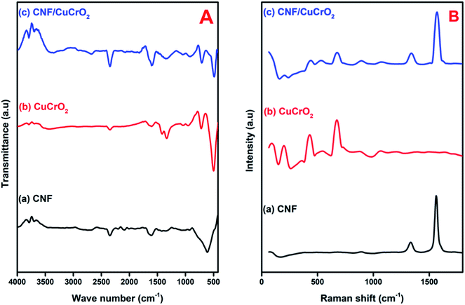 | ||
| Fig. 5 (A) FT-IR spectra of (a) CNF, (b) CuCrO2, (c) CNF/CuCrO2 composite. (B) Raman spectra of (a) CNF, (b) CuCrO2, (c) CNF/CuCrO2 composite. | ||
Raman spectroscopy was used to identify the formation of carbon-based materials. Fig. 5B presents the Raman spectra of the (a) CNF, (b) CuCrO2, and (c) CNF/CuCrO2 material. In the Raman spectra of CNF, D band at 1364 cm−1 and the G band at 1584 cm−1 suggested that the graphitic band. The D band was attributed to the disordered (sp2 site) existence of the graphite formation, and the G band, to the C–C stretching of the graphite material. The Raman spectra of prepared CuCrO2 consisted of two modes at 452 cm−1 and 703 cm−1 for Eg and A1g and some weak modes found at 208 cm−1 and 536 cm−1 due to Cu vacancies. The Raman spectra for CNF/CuCrO2 composite showed peak around 1345 cm−1 and 1580 cm−1 for the bare CNF and CuCrO2 samples.
The precise binding state and the chemical composition arrangement of the as-prepared CNF/CuCrO2 composite were studied by XPS analysis. The obtained wide scan survey spectrum of the as-prepared CNF/CuCrO2 composite is presented in Fig. 6A. All the elements, namely, Cu, Cr, C, and O, were observed in the wide scan spectrum, revealing the successful formation of the CuCrO2/CNF composite. Fig. 6B shows the high-resolution spectra of Cu 2p. The two main peaks were Cu 2p1/2 and Cu 2p3/2 at 960.49 and 940.50 eV, corresponding with the spin-orbital splitting energy of about ΔCu 2p = 19.9 eV, in good accordance with the reported data of the CuCrO2 phase.30,43,44 These observed results indicated that Cu existed in the +1 oxidation state. In addition to that, the Cu spectrum exhibited two satellite peaks at 950.24 and 942.95 eV, corresponding to the +2 oxidation ionic state of Cu 2p1/2 and Cu 2p3/2. These results suggested that the Cu retained both +1 and +2 oxidation states in the prepared CuCrO2/CNF catalyst. The binding energies of Cr indexed at 584.29 and 577.44 eV are attributed to the ionic state of +3 in the prepared CuCrO2/CNF catalyst (Fig. 6C). Furthermore, the incorporation of CNF into the CuCrO2 showed the presence of a C 1s peak with its consisting binding energies at 292.92 and 284.85 eV (Fig. 6D). The C 1s peaks illustrated the combination of C–C bands at 285.85 eV and the carboxyl carbon peak (O–C![[double bond, length as m-dash]](https://www.rsc.org/images/entities/char_e001.gif) O) observed at 292.92 eV. Fig. 6E presents the O 1s spectrum. It can be deconvoluted into two peaks separated at binding energies of 540.45 and 539.18 eV and belonging to the oxygen vacancy surface defects and adsorbed oxygen forming single-bonded carbon (C–O).4,5 Finally, the XPS studies confirmed the formation of the CNF/CuCrO2 composite.
O) observed at 292.92 eV. Fig. 6E presents the O 1s spectrum. It can be deconvoluted into two peaks separated at binding energies of 540.45 and 539.18 eV and belonging to the oxygen vacancy surface defects and adsorbed oxygen forming single-bonded carbon (C–O).4,5 Finally, the XPS studies confirmed the formation of the CNF/CuCrO2 composite.
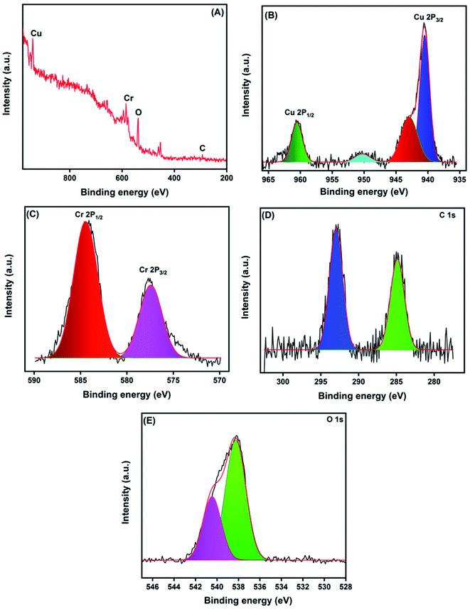 | ||
| Fig. 6 XPS survey spectrum of CNF/CuCrO2 composite (A), core level spectrum of Cu 2p (B), Cr 2p (C), C 1s (D), and O 1s (E). | ||
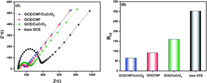
EIS is an important electroanalytical technique, and it has widespread applications in research for analyzing various phenomena, namely electrode-material interfacial resistance, charge transfer kinetics, mass transfer property, and diffusion coefficients. It is also used to characterize and monitor electrical conductivity and the sensitivity of an electrochemical system. The electrochemical activity of the prepared catalyst was checked in 5 mM [Fe(CN)6]3−/4−. The Nyquist plot was obtained from a frequency spectrum of 100 mHz to 100 kHz in 0.1 M KCl solution, and the obtained results for different prepared electrodes are shown in Fig. 7A. The plot generally comprises two regions, namely, a semicircular zone and a linear zone. The semicircular zone, at a higher amplitude region, is ascribed to the charge transfer resistance (Rct), while the linear zone, at a lower frequency region, is attributed to the diffusion process. From the obtained results, it was observed that the bare GCE exhibited a higher Rct value of about 303 Ω, indicating a poor electron transfer process at the bare GCE. The CuCrO2 fabricated on the GCE showed lower resistance than that of the bare GCE, and the Rct value notably decreased to 166 Ω, due to its excellent catalytic property. With the surface modification of GCE with CNF, the resistance was lower because it had a high basic surface area, which could enable the direct electron kinetics reaction process with good electrical conductivity. The Rct value was about 92 Ω. The GCE/CNF/CuCrO2 electrode delivered a very low Rct value of 65 Ω due to the synergistic effect of CuCrO2 and CNF. The findings clearly illustrate that the GCE/CNF/CuCrO2 exhibited an excellent electrocatalytic kinetics process, and the Rct value was much lower than those of other electrodes. The Rct values of bare GCE, GCE/CuCrO2, GCE/CNF, and GCE/CNF/CuCrO2 electrodes are compared in Fig. 7B.
3.2 Electrochemical performance of 4-nitrophenol at modified electrodes
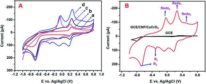
The electrochemical studies of 4-NP by different electrodes were analyzed by the CV method. Fig. 8A displays the CV response from the unmodified GCE, GCE/CNF, GCE/CuCrO2, and GCE/CNF/CuCrO2 in the presence of 4-NP in N2 purged PBS at pH 5.0. Without the addition of 4-NP in 0.5 M PBS, there was no electrochemical response in this potential range. The results for all the aforementioned electrodes in response to the redox reaction of 4-NP are listed in Table 1. With the bare GCE, the redox peaks for 4-NP were very small, at about 0.2 V. The intensities of the redox peaks increased steadily for the GCE modified with CNF, CuCrO2, and CNF/CuCrO2 composites. The electrocatalytic response of CNF/CuCrO2 to 4-NP was higher than those of bare GCE, CNF, and CuCrO2. The GCE/CNF/CuCrO2 electrode exhibited a high peak current for 4-NP reduction due to the high surface area and good electron transfer properties (Fig. 8B). Moreover, the synergistic effect of CNF and CuCrO2 made the GCE/CNF/CuCrO2 composite exhibit the highest electrocatalytic activity for 4-NP detection.| Electrode materials | Linear range (μM) | Detection limit (μM) | Ref. |
|---|---|---|---|
| GCE/CNF/CuCrO2 | 0.1–150 | 0.022 | This work |
| Nafion/Mb-HAp@CNF/CILE | 0.3–10.0 | 0.23 | 36 |
| GO/GCE | 0.1–120 | 0.02 | 1 |
| OMCs/GCE | 2.0–90 | 0.1 | 24 |
| f-MWCNTs/ZrO2/GCE | 2–26 | 0.03 | 9 |
| Silver particles/GCE | 1.5–140 | 0.5 | 44 |
| AgA-PE | 0.2–100 | 0.3 | 45 |
| DTD/Ag NP/CPE | 1–100 | 0.25 | 46 |
| ERG/AuNP/GCE | 0.036–90 | 10 | 47 |
| Kao/IL/PdNP/GCE | 0.5–4.5 | 22 | 48 |
| PCZ/NGE/GCE | 0.8–20 | 62 | 49 |
| AgNW@PANI/GCE | 0.6–32 | 52 | 50 |
| SWCNT/GCE | 0.01–5.0 | 2.5 | 6 |
| CeO2–Cu2O | — | 2.85 | 51 |
| CeO2–Cu2O/CH | — | 2.03 | 51 |
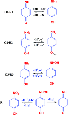
The electrochemical activity of GCE/CNF/CuCrO2 4-NP is shown in Fig. 8B. The figure shows a pair of main 4-NP oxidation/reduction (redox) peaks (O1/R1) at around 0.2 V. Moreover, 4-NP exhibits two pairs of weak oxidation/reduction peaks (O2/R2 and O3/R3) at 0.4 and 0.6 V and two reduction peaks (R) at 0.4 and 0.6 V. The reversible two-electron redox reaction of 4-aminophenol is shown by the three pairs of redox (oxidation/reduction) peaks (O1/R1, O2/R2, and O3/R3). To create the hydroxylamine species, the two R peaks exhibit an irreversible reduction of the nitro group. The possible electrocatalytic reactions of 4-NP on the GCE/CNF/CuCrO2 electrode are described in Scheme 2. The overall electrochemical redox activity of 4-NP is very close to that of previously recorded work.45–51 Fig. 9A shows that the electrochemical performance of GCE/CNF/CuCrO2 improved when the concentration of 4-NP was increased, and the corresponding linear range was from 0.1 to 200 μM. Fig. 9B presents the corresponding linear relation between the concentration of 4-NP and the peak current (Ip) for the 4-NP oxidation.
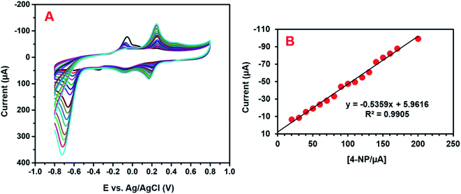 | ||
| Fig. 9 (A) The obtained CV response for the GCE/CNF/CuCrO2 electrode for the detection of 0.1 to 200 μM 4-NP in PBS. (B) Calibration plot between the peak current and concentration of 4-NP. | ||
3.3 Effects of different pH on 4-NP detection
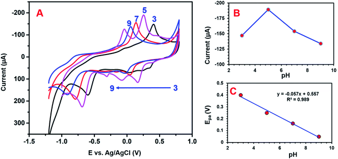
Electrolyte pH conditions can strongly influence the electrochemical detection of 4-NP. The influence of pH was investigated using CV studies. The peak current and potential of the 4-NP were close to the pH value of the electrolyte solution. Fig. 10A presents the electrochemical detection of 4-NP over the GCE/CNF/CuCrO2 electrode under various pH conditions. It can be seen that, when the pH increased from 3 to 5, the redox peak current equally increased, while at pH 5 to 9, the peak potential changed to the negative side and the peak current decreased. The highest redox peak current appeared at pH 5, so we used pH 5 for further electrochemical studies. The high redox response at pH 5 might have been related to the strong interaction between the negatively charged GCE/CNF/CuCrO2 electrode surface and the positively charged nitrophenol species (protonated). Furthermore, an acidic environment is more favorable for the redox reaction of 4-NP, in agreement with the proposed reactions in Scheme 2.4,6,7. The linear regression equation can be revealed as Epa (V) = −0.057 pH + 0.557 (R2 = 0.989), which is given below:| Ep = −(0.0592m/n) pH + b |
According to the Nernst equation, the ratio of m/n was identified as 1.42, where m is the number of proton transfers, T is temperature, n is the electron transfer number, R is the gas constant (8.314 J K−1 mol−1), and F is the Faraday constant (96![[thin space (1/6-em)]](https://www.rsc.org/images/entities/char_2009.gif) 485.33 C mol−1). Based on the Nernst equation, an equal number of electrons and protons were involved at the time of 4-NP detection over the GCE/CNF/CuCrO2 electrode. Moreover, Fig. 10B indicates that the maximum peak current response to pH was a pKa value of 4-NP, which determined that the non-dissociated 4-NP was adsorbed more over the GCE/CNF/CuCrO2 electrode. The linear relation between pH and peak current potential is shown in Fig. 10C. A slope of 57 mV pH−1 for the electrochemical reaction indicates an equal number of electron transfers with the GCE/CNF/CuCrO2 electrode.
485.33 C mol−1). Based on the Nernst equation, an equal number of electrons and protons were involved at the time of 4-NP detection over the GCE/CNF/CuCrO2 electrode. Moreover, Fig. 10B indicates that the maximum peak current response to pH was a pKa value of 4-NP, which determined that the non-dissociated 4-NP was adsorbed more over the GCE/CNF/CuCrO2 electrode. The linear relation between pH and peak current potential is shown in Fig. 10C. A slope of 57 mV pH−1 for the electrochemical reaction indicates an equal number of electron transfers with the GCE/CNF/CuCrO2 electrode.
3.4 Effect of different scan rates
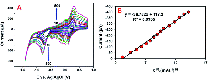
The electrocatalytic mechanism is generally obtained from the relation between the scan rate and peak current. The consequence of the scan rate on the reduction of 4-NP at the GCE/CNF/CuCrO2 electrode was also investigated in 0.05 M PBS containing 200 μM 4-NP at scan rates of 10–500 mV s−1. Fig. 11A shows that the redox peak currents linearly increased as the scan rate increased. In addition, the redox potential moved to the positive and negative sides as the scan rate rose. Fig. 11B presents the plot of redox peak current vs. square root of scan rate. The corresponding linear regression equation can be revealed as eqn (3): Ip = −36.752ν1/2 + 117.2 (R2 = 0.9955). This result indicates that the detection process of 4-NP over the GCE/CNF/CuCrO2 electrode is diffusion-controlled. These results reveal that the GCE/CNF/CuCrO2 electrode has outstanding electrochemical properties due to its high porosity and excellent electrocatalytic function. Furthermore, the high surface area of the GCE/CNF/CuCrO2 electrode creates fast electron transfers between the electrode and 4-NP.3.5 Determination of 4-NP by DPV studies
DPV is a more responsive method than other cyclic voltammetric systems. Hence, we conducted DPV studies for determining the sensitivity, linearity, and detection limit of the modified electrode. Fig. 12A depicts the DPV responses of 4-NP reduction on GCE/CNF/CuCrO2 in 0.05 M PBS with different concentrations of 4-NP (0.1–150 μM). The reduction peak current rose with increases in the concentration of 4-NP. Fig. 12B reveals that the linear concentration range of the modified electrode was 0.1–150 μM and the detection limit (LOD) was 0.022 μM. Moreover, the sensitivity of the GCE/CNF/CuCrO2 electrode was 20.02 μA μM−1 cm−2, which was greater than those of other 4-NP sensors. The obtained results are compared with those of the reported 4-NP sensors in Table 1. The GCE/CNF/CuCrO2 electrode presents better results for the identification of 4-NP due to the greater electron transfer rate and good catalytic properties of CuCrO2. Furthermore, the high surface area of CNF allows for close interaction between the CNF and CuCrO2. Therefore, the GCE/CNF/CuCrO2 electrode is a superb electrode material for the electrochemical identification of 4-NP.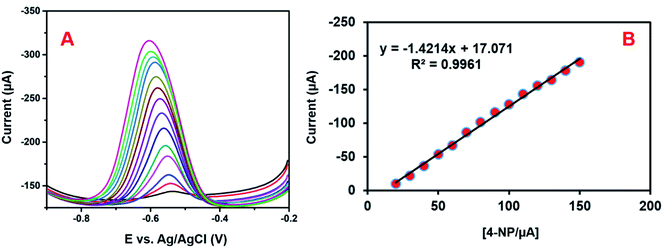 | ||
| Fig. 12 (A) DPV performance of GCE/CNF/CuCrO2 electrode in 4-NP solution at different concentrations. (B) Plot of peak current versus concentration of 4-NP. | ||
3.6 Repeatability, reproducibility and stability studies
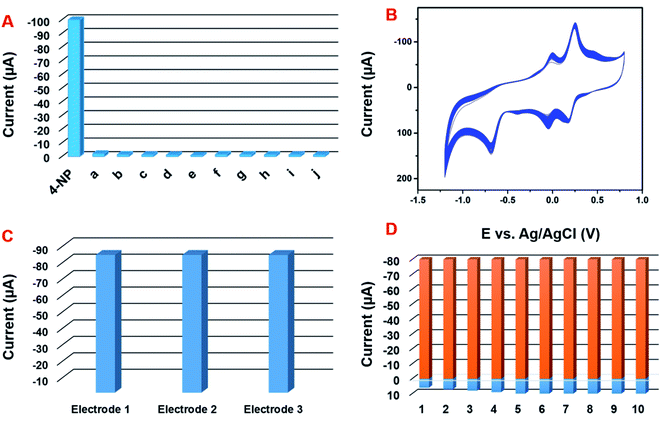
The selectivity behavior of the GCE/CNF/CuCrO2 electrode was studied with the DPV system in the presence of 20 μM 4-NP in acetate PBS solution along with interference molecules and ions, namely, (a) Zn2+, (b) Co2+, (c) Ni2+, (d) Na+, (e) Mg2+, (f) Ca2+, (g) K+, and (h) NO3−. The 4-NP response showed no loss, even in the presence of interfering metal ion species (Fig. 13A). The results strongly indicate that the GCE/CNF/CuCrO2 electrode is suitable for selective detection of 4-NP. Moreover, the operational stability of the electrode was examined by a CV technique in the presence of 100 μM 4-NP. The experimental performance showed a 4-NP peak current loss of only 2.3% from the initial current (Fig. 13B). The obtained results indicate good operational stability. Moreover, storage stability is understood to be a main factor in electrochemical sensor studies. The storage stability of the GCE/CNF/CuCrO2 electrode was examined periodically in 100 μM of PBS containing 4-NP. After 15 days of storage, the GCE/CNF/CuCrO2 electrode showed a peak current change of 3.3% from its initial peak response. The reproducibility and repeatability of the GCE/CNF/CuCrO2 electrode were examined by cyclic voltammetry in PBS including 0.1 mM 4-NP. The GCE/CNF/CuCrO2 electrode demonstrated reasonable reproducibility of 2.74% in 10 independent studies with 10 independent electrodes (Fig. 13C). The prepared electrodes presented an acceptable percentage of current performance, 2.32% for 10 repeated measurements conducted with a single GCE/CNF/CuCrO2 electrode (Fig. 13D). These studies provide further evidence that the GCE/CNF/CuCrO2 electrode has excellent repeatability and reproducibility. All these aforementioned studies indicate that the GCE/CNF/CuCrO2 electrode has excellent repeatability, reproducibility, and stability.3.7 Real sample analysis
The practical ability of the prepared electrode to detect 4-NP was examined by the CV method using tap water, industrial waste water and river water, and the obtained CV results are given in S. Fig. 1A–C. The tap water samples were collected from our laboratory and the river water samples were collected from the Yonghe River in Taipei. The industrial waste water was collected from nearby factory in Taipei. The collected samples were used for real sample analysis with the GCE/CNF/CuCrO2 modified electrode. Before the real sample identification, the collected water samples were centrifuged at 2000 rpm to remove contaminants and the pH was adjusted to 5.0. After that, the real sample studies showed no 4-NP signal unless 4-NP was added, indicating that the 4-NP concentration was lower than the detection limit. For this reason, the conventional standard addition approach was used for the recovery of the actual real sample analysis, and the results are listed in Table 2. In the real sample experiment, the GCE/CNF/CuCrO2 electrode exhibited an admissible recovery percentage of 95–99.5%. Therefore, these results exhibit that the GCE/CNF/CuCrO2 electrode is reliable and has potential for the detection of 4-NP in real samples.| Samples | Added (μM) | Found (μM) | Recovery (%) | (RSD) (%) |
|---|---|---|---|---|
| Tap water | 10 | 9.8 | 98 | 3.2 |
| 10 | 19.9 | 99.5 | 2.7 | |
| River water | 10 | 9.3 | 93 | 3.5 |
| 10 | 19.5 | 97.5 | 3.7 | |
| Industrial waste water | 10 | 9.5 | 95 | 3.2 |
| 10 | 19.7 | 98.5 | 2.8 |
4. Electrochemical performance
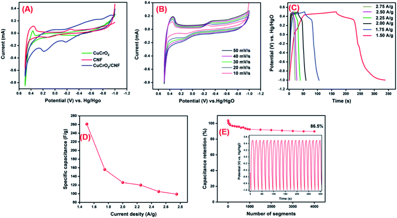
The CNF/CuCrO2 composite with nickel foam (NF) was used as a supercapacitor electrode. The electrochemical behavior of the prepared CNF/NF, CuCrO2/NF, CNF/CuCrO2/NF electrodes was determined by the cyclic voltammetry (CV) technique and the galvanostatic charge–discharge (GCD) measurement of the standard three-electrode cell system in 1 M KOH liquid electrolyte. Fig. 14A displays the CV profiles of the CNF/NF, CuCrO2/NF, and CNF/CuCrO2/NF electrodes at a scan rate of 10 mV s−1. The CV shows that the curve obtained for CNF/CuCrO2/NF electrode was larger than those of the CNF/NF and CuCrO2/NF, indicating better charge storage and stability. In addition, the specific capacitances of CNF/NF, CuCrO2/NF, and CNF/CuCrO2/NF electrodes were determined using CV curves with the following eqn (1).37,38
 | (1) |
 is the integral region of the CV peak. The specific capacitance values for CNF/NF, CuCrO2/NF, and CNF/CuCrO2/NF were 103, 54, and 159 F g−1, respectively. The capacitance values for the CNF/CuCrO2/NF electrode were higher than those for CNF/NF and CuCrO2/NF electrodes due to the high rate of ion exchange on the electrode surface.
Fig. 14B shows the electrochemical behavior of the CNF/CuCrO2/NF electrode at an operating potential range of 0.5–1.0 V at various scan rates (10–50 mV s−1). The CV curves exhibit distinctive redox peaks, suggesting the charge storage mechanism of the CNF/CuCrO2/NF electrodes, which were regulated by a faradaic redox reaction mechanism and thus possessed pseudo-capacitive actions relative to the Cu2+/Cu+ pair. Moreover, anodic and cathodic peak separation improved from a lower scanning rate to higher scanning rates for electrode polarization and ohmic resistance during redox reactions. The redox peak and shapes of the curves appeared up to the higher scan rate of 50 mV s−1 due to improved electron conduction and mass transfer inside the electrode.
GCD studies were used to examine further electrochemical properties of the supercapacitor materials. Fig. 14C presents the GCD studies of CNF/CuCrO2/NF at current densities of 1.50, 1.75, 2.00, 2.25, 2.50, and 2.75. The discharge curves exhibited a pseudocapacitance performance that was compatible with the above-mentioned CV results. The CNF/CuCrO2/NF electrode had average specific capacitances of 261, 156, 126, 120, 105, and 99 A g−1 at those current densities, respectively. As shown in Fig. 14D, the obtained real capacitance of the present CNF/CuCrO2/NF electrode was very comparable to those of several reported electrodes. From these studies, the specific capacitance of the CNF/CuCrO2/NF electrode is reduced with increasing current density.39,46
In addition, stability is one of the main requirements for supercapacitor fabrication. Fig. 14D presents the cycle stability of the CNF/CuCrO2/NF composite electrode, which was explored by repeated GCD between −1.0 and 0.5 V over 4000 segments at a current density of 5 A g−1. The specific capacitance measured for certain intermittent cycles is plotted against the corresponding cycles (Fig. 1D inset). The specific capacitance of the CNF/CuCrO2/NF electrode decreased by 13.5%, and about 86.5% capacitance remained. The CNF/CuCrO2/NF electrode showed excellent stability and high precise capacitance due to the inclusion of CNF and CuCrO2. Therefore, the capacitance performance of the CNF/CuCrO2/NF electrode was higher than those of previously recorded materials, as shown in S. Table 1. Based on the aforesaid electrochemical studies, the prepared CNF/CuCrO2/NF compound has remarkable potential for use as an electrode material in supercapacitor devices.
5. Conclusions
In conclusion, we have successfully prepared a CNF/CuCrO2 composite via hydrothermal methods. The prepared composite was characterized by X-ray diffraction, scanning transmission electron microscopy, CHI cyclic voltammetry studies, and scanning electron microscopy. The GCE/CNF/CuCrO2 modified electrode exhibits a high peak current response for the detection of 4-NP due to its high electrochemical activity. The GCE/CNF/CuCrO2 electrode shows excellent performance in the reduction of 4-NP because of the π–π interaction between the electrode materials and 4-NP. Furthermore, the linear response range of 4-NP was found to be 0.1–150 μM, the sensitivity was 20.02 μA μM−1 cm−2, and the detection limit was 0.022 μM. The real sample studies of the GCE/CNF/CuCrO2 electrode in water samples produced acceptable detection levels. The GCE/CNF/CuCrO2 electrode has outstanding selectivity, stability, sensitivity, and reproducibility for the detection of 4-NP. At a current density of 5 A g−1, the CNF/CuCrO2/NF composite coated Ni foam electrode has a high specific capacitance of 159 F g−1 with an excellent electron transfer rate capability and cyclability. Therefore, the GCE/CNF/CuCrO2 electrode presented herein can be used for the identification of 4-NP and for energy storage application.Conflicts of interest
The authors declare no competing financial interest.Acknowledgements
The Ministry of Science and Technology of Taiwan supported this work (MOST 109-2221-E-027-059 and 109-2222-E-027-001). The author is grateful to the Precision Research and Analysis Center of the National Taipei University of Technology (NTUT) for providing the measurement facilities.References
- J. Li, D. Kuang, Y. Feng, F. Zhang, Z. Xu and M. Liu, J. Hazard. Mater., 2012, 201–202, 250–259 CrossRef CAS PubMed.
- M. Ramalingam, V. K. Ponnusamy and S. N. Sangilimuthu, Environ. Sci. Pollut. Res., 2020, 27, 17481–17491 CrossRef CAS PubMed.
- S. B. Khan, K. Akhtar, E. M. Bakhsh and A. M. Asiri, Appl. Surf. Sci., 2019, 492, 726–735 CrossRef CAS.
- R. Madhu, C. Karuppiah, S. M. Chen, P. Veerakumar and S. Bin Liu, Anal. Methods, 2014, 6, 5274–5280 RSC.
- P. Wang, J. Xiao, M. Guo, Y. Xia, Z. Li, X. Jiang and W. Huang, J. Electrochem. Soc., 2015, 162, H72–H78 CrossRef CAS.
- C. Yang, Microchim. Acta, 2004, 148, 87–92 CrossRef CAS.
- Y. Tang, R. Huang, C. Liu, S. Yang, Z. Lu and S. Luo, Anal. Methods, 2013, 5, 5508–5514 RSC.
- Y. Cheng, Y. Li, D. Li, B. Zhang, R. Hao and S. Sang, Int. J. Electrochem. Sci., 2017, 12, 7754–7764 CrossRef CAS.
- B. Devadas, M. Rajkumar, S. M. Chen and P. C. Yeh, Anal. Methods, 2014, 6, 4686–4691 RSC.
- S. B. Khan, K. Akhtar, E. M. Bakhsh and A. M. Asiri, Appl. Surf. Sci., 2019, 492, 726–735 CrossRef CAS.
- A. Liao, P. Li, H. Zhang, M. Guo, Y. Xia, Z. Li and W. Huang, J. Electrochem. Soc., 2017, 164, H63–H69 CrossRef CAS.
- I. Tapsoba, S. Bourhis, T. Feng and M. Pontié, Electroanalysis, 2009, 21, 1167–1176 CrossRef CAS.
- M. Govindhan, T. Lafleur, B. R. Adhikari and A. Chen, Electroanalysis, 2015, 27, 902–909 CrossRef CAS.
- F. Jalali, A. T. AbdAli and Z. Hasanvand, Adv. Environ. Sci. Technol., 2018, 4, 51–60 Search PubMed.
- A. Arvinte, M. Mahosenaho, M. Pinteala, A. M. Sesay and V. Virtanen, Microchim. Acta, 2011, 174, 337–343 CrossRef CAS.
- L. qiang Luo, X. lian Zou, Y. ping Ding and Q. sheng Wu, Sens. Actuators, B, 2008, 135, 61–65 CrossRef.
- D. Hofmann, F. Hartmann and H. Herrmann, Anal. Bioanal. Chem., 2008, 391, 161–169 CrossRef CAS PubMed.
- D. K. Dang, C. Sundaram, Y. L. T. Ngo, W. M. Choi, J. S. Chung, E. J. Kim and S. H. Hur, Dyes Pigm., 2019, 165, 327–334 CrossRef CAS.
- M. A. El Mhammedi, M. Achak, M. Bakasse and A. Chtaini, J. Hazard. Mater., 2009, 163, 323–328 CrossRef CAS PubMed.
- W. Huang, C. Yang and S. Zhang, Anal. Bioanal. Chem., 2003, 375, 703–707 CrossRef CAS PubMed.
- H. Yin, Y. Zhou, S. Ai, X. Liu, L. Zhu and L. Lu, Microchim. Acta, 2010, 169, 87–92 CrossRef CAS.
- Y. Zeng, Y. Zhou, T. Zhou and G. Shi, Electrochim. Acta, 2014, 130, 504–511 CrossRef CAS.
- T. Zhang, Q. Lang, D. Yang, L. Li, L. Zeng, C. Zheng, T. Li, M. Wei and A. Liu, Electrochim. Acta, 2013, 106, 127–134 CrossRef CAS.
- T. W. Chiu, B. S. Yu, Y. R. Wang, K. Te Chen and Y. Te Lin, J. Alloys Compd., 2011, 509, 2933–2935 CrossRef CAS.
- Y. T. Nien, M. R. Hu, T. W. Chiu and J. S. Chu, Mater. Chem. Phys., 2016, 179, 182–188 CrossRef CAS.
- T. W. Chiu, Y. C. Yang, A. C. Yeh, Y. P. Wang and Y. W. Feng, Vacuum, 2013, 87, 174–177 CrossRef CAS.
- R. Manickam, J. Yesuraj and K. Biswas, Mater. Sci. Semicond. Process., 2020, 109, 104928 CrossRef CAS.
- S. Zhou, X. Fang, Z. Deng, D. Li, W. Dong, R. Tao, G. Meng and T. Wang, Sens. Actuators, B, 2009, 143, 119–123 CrossRef.
- A. Varga, G. F. Samu and C. Janáky, Electrochim. Acta, 2018, 272, 22–32 CrossRef CAS.
- B. Tong, Z. Deng, B. Xu, G. Meng, J. Shao, H. Liu, T. Dai, X. Shan, W. Dong, S. Wang, S. Zhou, R. Tao and X. Fang, ACS Appl. Mater. Interfaces, 2018, 10, 34727–34734 CrossRef CAS PubMed.
- J. Sun, Y. Liu, S. Lv, Z. Huang, L. Cui and T. Wu, Electroanalysis, 2016, 28, 439–444 CrossRef CAS.
- J. Huang, Y. Liu and T. You, Anal. Methods, 2010, 2, 202–211 RSC.
- Z. Huo, Y. Zhou, Q. Liu, X. He, Y. Liang and M. Xu, Microchim. Acta, 2011, 173, 119–125 CrossRef CAS.
- Q. Guo, J. Huang, P. Chen, Y. Liu, H. Hou and T. You, Sens. Actuators, B, 2012, 163, 179–185 CrossRef CAS.
- Y. Yang, R. Fu, J. Yuan, S. Wu, J. Zhang and H. Wang, Microchim. Acta, 2015, 182, 2241–2249 CrossRef CAS.
- J. Mu, C. Shao, Z. Guo, Z. Zhang, M. Zhang, P. Zhang, B. Chen and Y. Liu, ACS Appl. Mater. Interfaces, 2011, 3, 590–596 CrossRef CAS PubMed.
- H. Cheng and H. M. Duong, RSC Adv., 2015, 5, 30260–30267 RSC.
- N. Arjun, G. T. Pan and T. C. K. Yang, Results Phys., 2017, 7, 920–926 CrossRef.
- V. Veeramani, R. Madhu, S. M. Chen and M. Sivakumar, ACS Sustainable Chem. Eng., 2016, 4, 5013–5020 CrossRef CAS.
- V. Veeramani, R. Madhu, S. M. Chen, M. Sivakumar, C. Te Hung, N. Miyamoto and S. Bin Liu, Electrochim. Acta, 2017, 247, 288–295 CrossRef CAS.
- C. Wang, F. Li, H. Qu, Y. Wang, X. Yi, Y. Qiu, Z. Zou, Y. Luo and B. Yu, Electrochim. Acta, 2015, 158, 35–41 CrossRef CAS.
- N. I. Ikhsan, P. Rameshkumar and N. M. Huang, Electrochim. Acta, 2016, 192, 392–399 CrossRef CAS.
- J. Crêpellière, P. L. Popa, N. Bahlawane, R. Leturcq, F. Werner, S. Siebentritt and D. Lenoble, J. Mater. Chem. C, 2016, 4, 4278–4287 RSC.
- J. Liu, W. Weng, H. Xie, G. Luo, G. Li, W. Sun, C. Ruan and X. Wang, ACS Omega, 2019, 4, 15653–15659 CrossRef CAS PubMed.
- I. G. Casella and M. Contursi, J. Electrochem. Soc., 2007, 154, D697 CrossRef CAS.
- A. Niaz, J. Fischer, J. Barek, B. Yosypchuk, Sirajuddin and M. I. Bhanger, Electroanalysis, 2009, 21, 1786–1791 CrossRef CAS.
- G. Rounaghi, R. M. Kakhki and H. Azizi-Toupkanloo, Mater. Sci. Eng., C, 2012, 32, 172–177 CrossRef CAS.
- X. X. Jiao, H. Q. Luo and N. B. Li, J. Electroanal. Chem., 2013, 691, 83–89 CrossRef CAS.
- G. Kenne Dedzo, E. Pameté Yambou, M. R. Topet Saheu, G. Ngnie, C. P. Nanseu-Njiki, C. Detellier and E. Ngameni, J. Electroanal. Chem., 2017, 801, 49–56 CrossRef CAS.
- Y. Zhang, L. Wu, W. Lei, X. Xia, M. Xia and Q. Hao, Electrochim. Acta, 2014, 146, 568–576 CrossRef CAS.
- C. Zhang, S. Govindaraju, K. Giribabu, Y. S. Huh and K. Yun, Sens. Actuators, B, 2017, 252, 616–623 CrossRef CAS.
Footnote |
| † Electronic supplementary information (ESI) available: Real sample analysis and comparison of the specific capacitance values of different oxide systems. See DOI: 10.1039/d1ra02783b |
| This journal is © The Royal Society of Chemistry 2021 |

