 Open Access Article
Analysis of zwitterionic membrane fouling mechanism caused by HPAM in the presence of electrolytes
Qin Jiang ab,
Zi-Yu Liu
 *a,
Wei Guoc,
Zengping Suc,
Wangjing Maa,
Lu Zhang
 a and
Sui Zhao*a
aKey Laboratory of Photochemical Conversion and Optoelectronic Materials, Technical Institute of Physics and Chemistry, Institute of Engineering Thermophysics, Chinese Academy of Sciences, Beijing 100190, People's Republic of China. E-mail: ziyuliu@mail.ipc.ac.cn; zhaosui@mail.ipc.ac.cn
bUniversity of Chinese Academy of Sciences, Beijing 100049, People's Republic of China
cInstitute of Food Science and Technology, Chinese Academy of Agricultural Sciences, Beijing 100193, People's Republic of China
First published on 4th May 2021
Abstract
Membrane fouling has always been a tough issue that is urgent to solve. Electrolytes which are prevalent in wastewater have a major influence on membrane fouling. Therefore, it is of great significance to understand the role and fouling mechanism of electrolytes in the membrane fouling process. In this work, the zwitterionic membrane is used to process hydrolyzed poly(acrylamide) (HPAM) with the addition of electrolytes (CaCl2, NaCl). Meanwhile, the effect of different electrolytes on the zwitterionic membrane fouling process by hydrolyzed poly(acrylamide) (HPAM) is systematically investigated. It was found that the flux recovery ratio (FRR) of the zwitterionic membrane is nearly 100% after treating HPAM with the addition of electrolytes. Therefore, molecular dynamics (MD) simulations were applied to illustrate the impact of electrolytes on the change of foulant structures and confirm the consequent effect of electrolytes on membrane fouling. According to the experiment and MD simulation results, it is found that the positive ion layer which exists between the HPAM and zwitterionic surface results in the excellent fouling resistance performance of the zwitterionic membrane. The zwitterionic membrane fouling mechanism is analyzed, which is helpful to the understanding of zwitterionic membrane fouling in high salinity wastewater.
1. Introduction
Membrane technology has drawn considerable attention to its prospective in processing wastewater.1,2 However, membrane fouling has a detrimental impact on both the separation performance and life span of the membranes. Therefore, clearing the mechanism of membrane fouling in different conditions can significantly affect the design of a highly-effective antifouling membrane.3There are multiple factors affecting membrane fouling, including the nature of the foulants and the properties of the membranes.4 For example, the size,5 hydrophilicity,6 and electrical properties7 of the foulants have a critical impact on membrane fouling. In addition, the surface structure,8 chemical properties,9 hydrophilicity,10,11 and charge12,13 of the membranes also affect the fouling of the membranes. What's more, it is worth mentioning that ions in the solution play a crucial role in the membrane fouling process. Ions may change the structure, charge, and size of the foulants, which can even cause the sediment of the foulants and aggravate the membrane fouling.14,15 Moreover, electrolytes could also interact with the modified membrane surface.16,17 Luo et al.18 found that Ca2+ can bind the carboxyl groups between whey protein and the negatively charged polyamide membrane surface to aggravate membrane fouling. Zwitterionic material which has two opposing electrical groups can adsorb abundant electrolytes especially bivalent cations as well,19 which may influence the interaction with foulants. As electrolytes are prevalent in wastewater, it is critical to pay attention to the combined effect of foulants, membranes and ions in the membrane fouling process.
As an effective means to explain the microscopic mechanism, molecular dynamics simulations can illustrate the interactions between the membrane and foulants from a molecular perspective.20,21 Liu et al.22 explored the effect of the hydration layer on the surface of zwitterionic membrane and the dynamic antifouling mechanism of the membrane for sodium alginate by molecular dynamics simulations. Talati et al.23 investigated the separation performance of carbon nanotube membranes for different heavy metal ions (Zn2+, Ni2+, Cd2+) in aqueous solutions using molecular dynamics simulations. However, simulations about the interfacial behavior of liquids on membrane surfaces24,25 still need to be further investigated. Most simulation studies used in investigating membrane fouling mainly concentrate on the effect of membrane properties or foulant characters at present, few studies systematically simulate the fouling process from foulant to membrane. Therefore, using molecular dynamics simulations combined with appropriate experiments to explore the interaction mechanism of membrane fouling process involving foulant changes and membrane properties is of great significance.26,27
The salt concentration of some highly mineralized oil fields in Tarim is as high as 110 ∼ 260 g L−1, in which the concentration of divalent ions such as Ca2+ and Mg2+ are higher than 5 g L−1 even can reach 10 g L−1.28 As the highly mineralized oil fields are not rare, it is practical to investigate the interaction between divalent salts (Ca2+) and membranes when treating this type of oilfield wastewater. Hydrolyzed poly(acrylamide) (HPAM), a common oil-displacement agent to enhance the oil recovery, is the key problem in the treatment of polymer-containing wastewater for decades. Due to the high polymerization, electrical, and chemical properties of the HPAM molecules, it is difficult to degrade them by simply physical, chemical or biological methods. As the concept of green chemistry is in vogue, the recycle of HPAM in wastewater by using membrane separation is another means to treat HPAM. However, the membrane fouling by HPAM cannot be ignored in the process of membrane separation. Therefore, HPAM is selected as foulant, the electrolyte CaCl2 and NaCl which widely exists in oil-field wastewater is used to investigate the fouling mechanism of zwitterionic membrane dealing with HPAM saline wastewater.
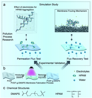
Herein, foulant HPAM and electrolyte CaCl2 and NaCl are used to investigate the fouling mechanism of zwitterionic membrane dealing with HPAM in saline wastewater. The HPAM structure under the impact of Ca2+ and Na+ is explored using MD simulations, then the successfully fabricated zwitterionic membrane is utilized to verify the effect of HPAM structural changes on zwitterionic membrane fouling process by experiments. After that, the interaction between Ca2+ combined NaCl and zwitterionic membrane surface is simulated while the synergy effect on the HPAM fouling process is discussed by combining simulations and experiments as well. The whole research process of zwitterionic membrane fouling is shown in Fig. 1a and related chemical structures are shown in Fig. 1c.
2. Methods and models
2.1. Details of the molecular dynamics simulations
In this work, all the simulations were performed using GROMACS 5.1 program. CHARMM36 force field was selected to describe the atoms' interaction, and the van der Waals interaction was chosen with a cut-off distance of 10 Å. Moreover, the temperature was set to 300 K while the pressure was 1 atm. A water box with 15![[thin space (1/6-em)]](https://www.rsc.org/images/entities/char_2009.gif) 000 water molecules was built at about 7 × 7 × 9 nm3. Then electrolyte–HPAM–water systems were established and run 30 ns to explore the effect of electrolyte for HPAM aggregation. The degree of hydrolysis for HPAM is 20%, and each linear HPAM chain contained 10 repeat units. 180Ca2+ and 360Cl− contains CaCl2 solution, 368Na+ and 360Cl− contains NaCl solution (8Na+ comes from hydrolysed HPAM) while 368Na+, 180Ca2+ with 720Cl− constructs NaCl + CaCl2 solution. 3 HPAM chains were used in the aggregated simulation. Based on the aggregated results, aggregated HPAM complex is selected to put into the zwitterionic membrane system combined with the water box with polymer surface and electrolytes and run 5 ns. The last 1 ns was used to analyze. The details about the building method were modeled according to the previous work.22 The grafted degree in the simulation part is described as RDMAPS (RDMAPS = 0%, 15%, 30%).
000 water molecules was built at about 7 × 7 × 9 nm3. Then electrolyte–HPAM–water systems were established and run 30 ns to explore the effect of electrolyte for HPAM aggregation. The degree of hydrolysis for HPAM is 20%, and each linear HPAM chain contained 10 repeat units. 180Ca2+ and 360Cl− contains CaCl2 solution, 368Na+ and 360Cl− contains NaCl solution (8Na+ comes from hydrolysed HPAM) while 368Na+, 180Ca2+ with 720Cl− constructs NaCl + CaCl2 solution. 3 HPAM chains were used in the aggregated simulation. Based on the aggregated results, aggregated HPAM complex is selected to put into the zwitterionic membrane system combined with the water box with polymer surface and electrolytes and run 5 ns. The last 1 ns was used to analyze. The details about the building method were modeled according to the previous work.22 The grafted degree in the simulation part is described as RDMAPS (RDMAPS = 0%, 15%, 30%).
Radial distribution function (RDF) refers to the ratio of local density to bulk density as a function of the distance from a reference point.29 In this paper, SDF was used to analyze the synergistic effect of electrolytes–HPAM–zwitterionic membrane. Meanwhile, the steered molecular dynamics (SMD) simulations were utilized to ensure the foulant reaches the membrane surface. Then a 5 ns-long NPT simulation was run after SMD simulations to obtain the natural states of HPAM molecules on different membrane surfaces, which can further investigate the fouling mechanism. The simulated process was the same as our previous work.22
2.2. Materials
PVDF microfiltration membrane with a nominal 0.1 μm pore size was procured from Ande Membrane Separation Technology & Engineering (Beijing) Co., Ltd. Zwitterionic monomer [2-(methacryloyloxy)ethyl]dimethyl-(3-sulfopropyl) (DMAPS) was provided by Aladdin industrial corporation. Benzophenone (BP), N,N′-methylenebis(acrylamide) (MBAA) and ammonium ceric nitrate (ACN) were all purchased from Shanghai Macklin Biochemical Co., Ltd. Poly(acrylamide) (HPAM, anion) was obtained from Adamas Reagent, Ltd. Paraffin liquid was acquired from Xilong Scientific Co., Ltd. Anhydrous ethanol, CaCl2 (≥96.0%) and ethylene glycol were all bought from Beijing Chemical Works. Deionized (DI) water was used to prepare all aqueous solutions.2.3. Fabrication and characterization of PVDF-g-DMAPS membranes
PVDF membrane was soaked in 5 wt% BP solution, and then the dried above membrane was immersed in freshly prepared reagent mixture which contains DMAPS monomer, MBAA and ACN (with a weight ratio of 1![[thin space (1/6-em)]](https://www.rsc.org/images/entities/char_2009.gif) :
:![[thin space (1/6-em)]](https://www.rsc.org/images/entities/char_2009.gif) 0.05
0.05![[thin space (1/6-em)]](https://www.rsc.org/images/entities/char_2009.gif) :
:![[thin space (1/6-em)]](https://www.rsc.org/images/entities/char_2009.gif) 0.05). The used DMAPS concentration is described as CDMAPS. Subsequently, the membrane was exposed to UV irradiation for 40 min. Finally, the membrane was taken out and washed drastically. Different zwitterionic membranes (CDMAPS = 0.1 wt%, 0.5 wt%, 1 wt%) were obtained by controlling the concentration of DMAPS monomer, and the whole process is shown in Fig. 1b.
0.05). The used DMAPS concentration is described as CDMAPS. Subsequently, the membrane was exposed to UV irradiation for 40 min. Finally, the membrane was taken out and washed drastically. Different zwitterionic membranes (CDMAPS = 0.1 wt%, 0.5 wt%, 1 wt%) were obtained by controlling the concentration of DMAPS monomer, and the whole process is shown in Fig. 1b.
SEM images were obtained from a Field emission scanning electron microscopy (Hitachi S4800, Japan) to observe the morphologies and microstructure of the membrane surfaces. Roughness measurement was operated on a roughness measurement device (Alicona InfiniteFocus G5, Austria) with the cut off wavelength of 25 μm. XPS was employed on an X-ray photoelectron spectroscopy (ESCALAB 250Xi, USA) to characterize the variation of membranes' surface chemistry before and after the modification. Both in-air water and underwater oil contact angles were measured by using an OCA20 machine (DataPhysics Company, Germany). When measuring the in-air water contact angles, the membranes were dried at 50 °C for 12 h previously. Then, the water droplet was carefully dropped on the membrane surface, photographed and calculated as soon as the droplet deposited on the membrane surface. Besides, the underwater oil contact angles were obtained via the approach which is similar to the captive bubble method by using oil (liquid paraffin) droplets. The membranes' underwater anti-oil-adhesion performance was evaluated on a tensiometer (DCAT11, Data Physics Instruments Co., Germany), wherein the relative position of the membrane and the oil droplet was controlled at a constant speed (0.005 mm s−1). Meanwhile, the interaction force was recorded and presented as an interaction force curve which was a function of the interaction distance and the interaction force. In each measurement, a membrane was fixed on a sheet of glass and placed in a quartz trough which was filled with DI water previously. To begin with, the distance between the bottom of the oil droplet and the membrane surface was set to be about 1.8 mm, and then the membrane would gradually approach the oil droplet in the advancing stage. Subsequently, the membrane began to squeeze the oil droplet at the same speed for approximately 0.2 mm after contacting the oil droplet. Finally, the movement direction of the membrane reversed immediately and stopped in the original position. The surface zeta potential was measured on a potentiometer (Zetasizer Nano ZSP, Malvern, UK). To test the surface zeta potential, the membrane is fixed between two electrodes. Then, the membrane and electrodes were submerged in an aqueous solution containing tracer particles. By detecting the apparent electrophoretic velocity of the tracer particles at different distances from the membrane surface, the membrane's surface zeta potential was obtained.
2.4. Membrane permeance and filtration performance
The permeance performance was tested by lab-scale dead-end filtration equipment with an effective membrane area of 10 cm2. The experiment was operated under 0.15 MPa for at least 30 min in advance until the flux remained steady. Thereafter the pressure was adjusted to 0.1 MPa to measure the permeance performance (Jw1, L (m2 h bar)−1). Four filtration solutions (50 mg L−1 HPAM and 50 mg L−1 HPAM solution with 10 g L−1 CaCl2/11.5 g L−1 NaCl whose mole fraction is corresponding to MD simulation) were prepared. The permeance (Jp, L (m2 h bar)−1) was calculated by eqn (1) when treating HPAM with or without electrolytes. After the rejection, the membrane was cleaned by DI water to measure the recovered flux (Jw2, L (m2 h bar)−1) again. The flux recovery ratio (FRR) was computed by eqn (2).
 | (1) |
 | (2) |
3. Results and discussion
3.1. Effect of electrolytes on the aggregation and complexation of HPAM
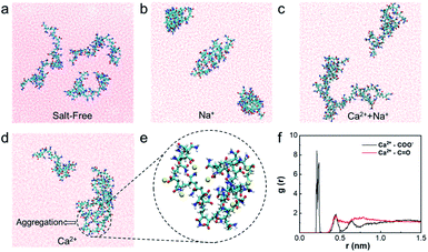
The natural states of HPAM can change if electrolytes exist in wastewater.30 Herein, the effect of divalent cation Ca2+/Na+ on HPAM aggregation is explored firstly via MD simulations. Fig. 2 shows different natural states of HPAM in water, NaCl solution, CaCl2 solution, NaCl and CaCl2 solution, respectively. The results show that all of the three HPAM polymer chains are stretched to the aqueous phase freely and independently under salt-free conditions (Fig. 2a). When merely adding Na+, the HPAM chains aggregate internally, but no aggregation occurs between the chains due to the weak interaction force (Fig. 2b). However, two HPAM chains can aggregate to form HPAM/cation complexes in CaCl2 solution (Fig. 2d and e), indicating the bridging role of Ca2+ in the aggregation of HPAM. When adding both Na+ and Ca2+, although aggregation also occurs in two HPAM chains (Fig. 2c), the aggregated complex seems to looser and more unstable than that in sole CaCl2 solution because of the weak force of Na+. Therefore, Ca2+ plays a critical role in the aggregation of HPAM. To further make out the role of Ca2+ in HPAM aggregation, part of aggregation is magnified in Fig. 2e. It can be seen that Ca2+ not only distributes inside a HPAM chain but also among multiple HPAM chains, which induces the shrink and complexation between HPAM chains. That is to say, the Ca2+ can increase the aggregated degree of foulant HPAM wile Na+ is incline to lead to HPAM shrink.To illustrate the aggregated structure clearly, radial distribution function (RDF), g(r) is analyzed based on the MD simulations. The RDF for the pair between Ca2+ and different hydrophilic groups of HPAM (–COO− and –C![[double bond, length as m-dash]](https://www.rsc.org/images/entities/char_e001.gif) O) are shown in Fig. 2f. The position of the first peak in RDF for –COO− and –C
O) are shown in Fig. 2f. The position of the first peak in RDF for –COO− and –C![[double bond, length as m-dash]](https://www.rsc.org/images/entities/char_e001.gif) O are 0.22 and 0.44 nm, respectively. The intensity of peak for –COO− is near ∼8.5, which is far strong than that for –C
O are 0.22 and 0.44 nm, respectively. The intensity of peak for –COO− is near ∼8.5, which is far strong than that for –C![[double bond, length as m-dash]](https://www.rsc.org/images/entities/char_e001.gif) O. Hence, the strong interaction force exists between the Ca2+ and –COO− group of HPAM, while the –C
O. Hence, the strong interaction force exists between the Ca2+ and –COO− group of HPAM, while the –C![[double bond, length as m-dash]](https://www.rsc.org/images/entities/char_e001.gif) O group barely interacts with Ca2+. The results agree well with the atomic structure shown in Fig. 2e. That is to say, Ca2+ mainly attaches to –COO− group of HPAM to link different polymer chains to form aggregations and complexation.
O group barely interacts with Ca2+. The results agree well with the atomic structure shown in Fig. 2e. That is to say, Ca2+ mainly attaches to –COO− group of HPAM to link different polymer chains to form aggregations and complexation.
3.2. Effect of HPAM aggregation on the membrane fouling by experiments
To verify the changes of the as-prepared membranes, the morphologies and microstructure of the membranes were observed by SEM (Fig. 3a). It can be seen from the SEM image that the pore size and porosity of the modified PVDF membranes decreased significantly with the increase of the DMAPS concentration. Besides, the porosity and the pore size of the membranes were obtained by the ImageJ software. The porosity of PVDF, 0.1% PVDF-g-DMAPS, 0.5% PVDF-g-DMAPS and 1% PVDF-g-DMAPS membranes are 8.51%, 3.56%, 2.08% and 0.22%, respectively. The average pore size of PVDF, 0.1% PVDF-g-DMAPS, 0.5% PVDF-g-DMAPS and 1% PVDF-g-DMAPS membranes are respectively 120 nm, 93.5 nm, 72 nm and 18 nm. The porosity and the pore size of the membranes continue to decrease with the increase of the DMAPS monomer, which is consistent with the membrane surface morphology in SEM images. Fig. 3b shows the 3D visualized roughness images of the membrane's surfaces. The original PVDF membrane has a relatively smooth surface with a roughness of 117.3 nm (Fig. 3c). It is obvious that the membrane surface becomes rougher as more DMAPS polymer grafted, which corresponds to the membranes' morphology changes in the SEM images.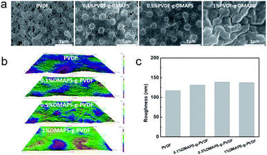 | ||
| Fig. 3 (a) The surface SEM images of PVDF membrane and PVDF-g-DMAPS membranes. (b) The 3D visualized roughness images of the membranes' surface. (c) The surface roughness values of the membranes. | ||
HPAM aggregation can drastically increase foulant size and even vitally aggravate the membrane fouling. To further explore the effect of aggregation induced by the electrolyte addition, the zwitterionic membrane (PVDF-g-DMAPS) is fabricated by UV photo-grafting. In the XPS spectra (Fig. 4a), the peak of S2p only emerges on the surface of the modified membrane at 167.5 eV and 166.3 eV, which indicates that zwitterionic monomer DMAPS grafting process was realized. The water permeability test, the contact angles31 of prepared zwitterionic membranes grafted with different DMAPS concentrations (CDMAPS) and the anti-oil-adhesion property32,33 of the zwitterionic membrane have been reported in our previous work.22 The obvious change of the wetting ability and oil adhesion force shows that the dominative role of grafted DMAPS on the zwitterionic membrane. 1% PVDF-g-DMAPS membrane are selected to make a further investigation as hydrophilic performance is stable.
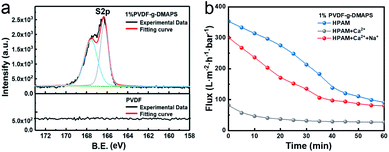 | ||
| Fig. 4 (a) XPS S2p spectra of 1% PVDF-g-DMAPS membrane and PVDF membrane. (b) The time-dependent flux of 1% PVDF-g-DMAPS membrane when treating HPAM with different ion conditions. | ||
Then the HPAM solutions with and without Ca2+ are filtered through 1% PVDF-g-DMAPS membrane to investigate the effect of HPAM/Ca2+ aggregation on zwitterionic membrane foulant (Fig. 4b). In the permeability test, the fluxes for zwitterionic membrane when treating HPAM with Ca2+, Na+ + Ca2+ and without electrolytes are 27.2 L (m2 h bar)−1, 79.6 L (m2 h bar)−1 and 86.7 L (m2 h bar)−1, respectively. As a result, the penetrating flux of zwitterionic membrane sharp declines when sole Ca2+ ions are added in the HPAM solution while flux has a slightly decrease with Na+ + Ca2+. This result is in line with above simulated results, the natural structure of HPAM will occur aggregation in the CaCl2 solution and such aggregation may lead to the reduced flux of 1% PVDF-g-DMAPS membrane. Nonetheless, such negative effect of aggregation on membrane foulant caused by Ca2+ can be relieved in some extent with the existence of a vast Na+. Given that the impact of interaction with electrolytes–HPAM on membrane fouling, it is necessary to study the interaction and fouling mechanism of electrolytes–HPAM–zwitterionic membrane.
3.3. Synergistic mechanism of electrolytes–HPAM–zwitterionic membrane on the fouling process
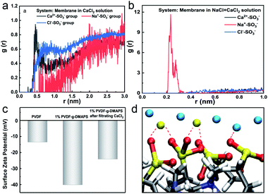
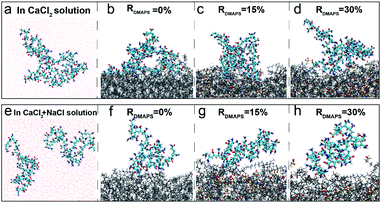
Based on the above-simulated results about HPAM/electrolytes aggregation, two HPAM chains as one foulant object are simulated with zwitterionic membrane and the synergistic mechanism is investigated. Fig. 5a shows the radial distribution of different ions around –SO3− groups of DMAPS in the Ca2+–zwitterionic membrane system. It is visually observable that the enrichment tendency of different ions (the distance) around the zwitterionic DMAPS are Ca2+ > Na+ > Cl−. However, the enrichment tendency of different ions around the zwitterionic DMAPS becomes Na+ > Ca2+ > Cl− when double doses of Na+ is added which means the competition between different positive ions. Anyhow, the distribution probability of Cl− is less than that of Na+ and Ca2+ in both conditions. That is to say, the positive ions have a higher enrichment on the membrane surface than negative ion. In other words, the zwitterionic surface tends to absorb cations. The above results indicate the existence of a cationic layer around the zwitterionic membrane surface, and the zwitterionic membrane exhibits a negatively charged surface to some extent to affect the ion distribution. To further confirm the existence of cationic layers on the zwitterionic membrane surface, the membranes' surface zeta potential is detected by experiments as shown in Fig. 5c. It can be seen that the zeta potential of the PVDF membrane decreased from −13.5 mV to −40.1 mV after grafting 1% DMAPS. After filtrating the CaCl2 solution, the zeta potential of the 1% DMAPS-g-PVDF membrane shifted to a positive direction to reach −24.1 mV, which implies that the zwitterionic membrane can attract the enrichment of positive ions. The diagram of interaction between Ca2+ and –SO3− groups of DMAPS is drawn in Fig. 5d. A cationic layer is formed at the membrane surface caused by the interaction between Ca2+/Na+ and –SO3− groups of DMAPS.The different surface charging state will influence the fouling process of the foulant HPAM. To reveal the fouling process of HPAM, the steered MD (SMD) simulations are performed, where the HPAM aggregation is dragged by a spring force to approach the membrane surface. The natural states of HPAM aggregation in the main phase of CaCl2/CaCl2 + NaCl solution and on zwitterionic membranes with different DMAPS grafting ratios were compared to verify the ability of the zwitterionic surface for resisting the fouling of HPAM under the CaCl2 condition by MD simulations. The aggregated structure of HPAM in CaCl2 solution is illustrated in Fig. 6a. It can be found that HPAM aggregation is loose but stable and can be freely stretched. HPAM aggregation distorts and part atoms tiles on the PVDF membrane surface (Fig. 6b), which means little resistance of PVDF membrane surface for HPAM complex adhesion. Compared with the natural states of HPAM on the PVDF membrane surface, part of the HPAM complex is prone to break away from the zwitterionic membrane surface as the grafting ratio of DMAPS increases to RDMAPS = 15% (Fig. 6c). When the grafting ratio of DMAPS reaches RDMAPS = 30%, HPAM aggregation whose loose structure is similar to that in CaCl2 solution tends to stretch to the aqueous phase freely and can hardly adhere to the zwitterionic surface under the Ca2+ condition (Fig. 6d). And this phenomenon can be attributed to the increased electric repulsion and hydrophilicity of the zwitterionic membrane. But it is worth noting that HPAM aggregation has broken out during the SMD process which implies the instability of aggregation in Ca2+ and Na+ system once again and this also can decrease the membrane fouling. Therefore, only one HPAM chain is displayed in Fig. 6f–h. Similar tendency can be seen in Ca2+ and Na+ system which the interaction of foulant and membrane surface decreases until disappears with the increase of DMAPS grafting ratio. And for 30% ratio membrane, foulant can be hardly pulled at the membrane surface in Ca2+ + Na+ condition. As a whole, the interaction of positive ions and zwitterionic membrane can improve the membrane antifouling ability.
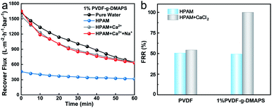
To verify the positive role of cation/zwitterionic membrane synergistic effect on membrane fouling, the recover fluxes of 1% PVDF-g-DMAPS membrane when treating HPAM with different electrolytes are measured by experiments (Fig. 7a). It can be seen that both the recovered flux of zwitterionic membrane using HPAM with Ca2+ or Ca2+ + Na+ are higher than that without electrolytes, which verifies the positive role of synergistic effect. The flux recovery ratio (FRR) is also illustrated in Fig. 7b. When treating HPAM aqueous solution, the recovery ratio of the zwitterionic membrane is only 49.4%, which is almost the same as the PVDF membrane. That is to say, although the hydrophilicity of the membrane surface is improved through grafting zwitterions, it has little influence on the HPAM fouling membrane process. However, it is amazing that the FRR of the 1% PVDF-g-DMAPS membrane can approach nearly 100% and the recovery flux is almost the same as the pure water flux (646.0 L (m2 h bar)−1) under the condition of positive ions, which is far higher than the value of PVDF membrane. To figure out whether the existence of Na+ will invalidate Ca2+, it is found that the recovered flux of zwitterionic membrane using HPAM with Ca2+ and Na+ is almost the same as the pure water flux of the 1% DMAPS-g-PVDF membrane, accordingly the FRR of the zwitterionic membrane is also almost 100% at this condition.
As we discussed above, the existence of HPAM/electrolytes aggregation will also impact the distribution of ions in this system. The positive cation layer also exists around the HPAM molecule. That is to say, massive cations exist around both zwitterionic membrane and HPAM molecules. The strong electrostatic repulsion will form when HPAM approaches the zwitterionic surface because of their cationic layers, thus impeding the adsorption of HPAM on the membrane surface to a great extent. That is to say when treating HPAM under the saline condition, the synergistic effect of cations–HPAM–zwitterionic membrane plays an irreplaceable role in improving the fouling-resistant ability of PVDF-g-DMAPS membrane. As a result, the residual HPAM complexes on the modified membrane surface are unstable so that they can be easily removed by simple hydraulic washing, thus the FRR of 1% PVDF-g-DMAPS membrane is approximately 100%. This phenomenon can well certify the positive effect of positive ions/zwitterionic membrane on membranes' antifouling ability. In other words, zwitterionic membrane is extremely suitable to apply in high salinity wastewater treatment because of the improvement of fouling-recovery ability when the existence of positive ions.
4. Conclusion
The effect of electrolytes on the fouling of zwitterionic membranes by HPAM is explored by using MD simulations combined experiments. It is confirmed that electrolyte plays two roles in the HPAM fouling zwitterionic membrane process. On the one hand, Ca2+ can make HPAM chains aggregate to increase the aggregated degree of foulant, which aggravates the fouling of membranes. However, Na+ can make the complex looser and more unstable to relieve the negative effect of aggregation on zwitterionic membrane. On the other hand, the existence of cationic layers (both Ca2+ and Na+) on the zwitterionic membrane surface can induce the electrostatic repulsion between HPAM and the zwitterionic surface, which will increase the fouling recovery of HPAM for the zwitterionic membrane. The special character enables the zwitterionic membrane to exhibit a flux recovery ratio of approximately 100%, demonstrating enhanced salt tolerance and fouling resistance under the condition of high salinity. Anyway, the study of the interaction mechanism of the electrolytes–HPAM–zwitterionic membrane provides new insight into the foulant fouling membrane process by combining simulation and experiments.Conflicts of interest
There are no conflicts to declare.Acknowledgements
The authors appreciate the financial support from the National Natural Science Foundation of China (No. 22075304) and National Key R&D Program of China (2017YFC1600903). The authors are grateful for the help of Yuxi Zhang for valuable experimental discussion.References
- N. K. Khanzada, M. U. Farid, J. A. Kharraz, J. Choi, C. Y. Tang, L. D. Nghiem, A. Jang and A. K. An, J. Membr. Sci., 2020, 598, 117672 CrossRef CAS.
- M. G. Buonomenna, RSC Adv., 2013, 3, 5694–5740 RSC.
- X. Shen, B. Gao, K. Guo, C. Yu and Q. Yue, Sci. Total Environ., 2019, 694, 133816 CrossRef CAS PubMed.
- S. Kim, K. H. Chu, Y. A. J. Al-Hamadani, C. M. Park, M. Jang, D. H. Kim, M. Yu, J. Heo and Y. Yoon, Chem. Eng. J., 2018, 335, 896–914 CrossRef CAS.
- W. Sun, J. Nan, J. Xing and J. Tian, RSC Adv., 2016, 6, 83456–83465 RSC.
- N. H. Lee, G. Amy, J. P. Croue and H. Buisson, Water Res., 2004, 38, 4511–4523 CrossRef CAS PubMed.
- D. Breite, M. Went, A. Prager and A. Schulze, RSC Adv., 2016, 6, 98180–98189 RSC.
- S. Heidari, M. Amirinejad and H. Jahangirian, Chem. Eng. Technol., 2019, 42, 1310–1320 CrossRef CAS.
- M. Asadollahi, D. Bastani and S. A. Musavi, Desalination, 2017, 420, 330–383 CrossRef CAS.
- L. Shen, X. Wang, R. Li, H. Yu, H. Hong, H. Lin, J. Chen and B. Q. Liao, J. Colloid Interface Sci., 2017, 505, 900–909 CrossRef CAS PubMed.
- X. Shi, Y. Chen, X. Zhang, X. Long and J. Qian, Chem. Eng. Sci., 2020, 212, 115330 CrossRef CAS.
- Z. Wang, J. Jin, D. Hou and S. Lin, J. Membr. Sci., 2016, 516, 113–122 CrossRef CAS.
- D. Breite, M. Went, I. Thomas, A. Prager and A. Schulze, RSC Adv., 2016, 6, 65383–65391 RSC.
- D. A. Z. Wever, F. Picchioni and A. A. Broekhuis, Prog. Polym. Sci., 2011, 36, 1558–1628 CrossRef CAS.
- X. You, J. Teng, Y. Chen, Y. Long, G. Yu, L. Shen and H. Lin, Chemosphere, 2020, 246, 125801 CrossRef CAS PubMed.
- A. E. Childress and M. Elimelech, J. Membr. Sci., 1996, 119, 253–268 CrossRef CAS.
- X. Hao, S. Gao, J. Tian, S. Wang, H. Zhang, Y. Sun, W. Shi and F. Cui, RSC Adv., 2019, 9, 38227–38234 RSC.
- J. Luo, L. Ding, Y. Wan, P. Paullier and M. Y. Jaffrin, Sep. Purif. Technol., 2012, 88, 79–86 CrossRef CAS.
- D. Huster and K. Arnold, Biophys. J., 1998, 75, 909–916 CrossRef CAS PubMed.
- D. T. Myat, M. B. Stewart, M. Mergen, O. Zhao, J. D. Orbell and S. Gray, Water Res., 2014, 48, 108–118 CrossRef CAS PubMed.
- Z. Lv, J. Hu, J. Zheng, X. Zhang and L. Wang, Ind. Eng. Chem. Res., 2016, 55, 4726–4733 CrossRef CAS.
- Z. Y. Liu, Q. Jiang, Z. Jin, Z. Sun, W. Ma and Y. Wang, ACS Appl. Mater. Inter., 2019, 11, 14408–14417 CrossRef CAS PubMed.
- S. Talati, A. Mohebbi and H. Dorrani, J. Eng. Thermophys., 2019, 28, 123–137 CrossRef CAS.
- Y. Wang, Z. Qin, M. J. Buehler and Z. Xu, Nat. Commun., 2016, 7, 12854 CrossRef CAS PubMed.
- S. Zhang, Y. Wang, H. He, F. Huo, Y. Lu, X. Zhang and K. Dong, Green Energy Environ, 2017, 2, 329–330 CrossRef.
- M. B. Stewart, D. T. Myat, M. Kuiper, R. J. Manning, S. R. Gray and J. D. Orbell, Carbohydr. Polym., 2017, 164, 162–169 CrossRef CAS PubMed.
- M. B. Tanis-Kanbur, S. Velioglu, H. J. Tanudjaja, X. Hu and J. W. Chew, J. Membr. Sci., 2018, 566, 140–150 CrossRef CAS.
- M. Zhou, J. Feng, T. Jiang, J. Liu and L. Zhou, Xinjiang Petroleum Geology, 2010, 31, 163–166 CAS.
- R. Wu, M. Deng, B. Kong, Y. Wang and X. Yang, J. Phys. Chem. B, 2009, 113, 12680–12686 CrossRef CAS PubMed.
- S. Peng and C. Wu, Macromolecules, 1999, 32, 585–589 CrossRef CAS.
- M. Tang, D. Hou, C. Ding, K. Wang, D. Wang and J. Wang, Sci. Total Environ., 2019, 696, 133883 CrossRef PubMed.
- Y. Zhu, J. Wang, F. Zhang, S. Gao, A. Wang, W. Fang and J. Jin, Adv. Funct. Mater., 2018, 28, 1804121 CrossRef.
- S. Gao, Y. Zhu, J. Wang, F. Zhang, J. Li and J. Jin, Adv. Funct. Mater., 2018, 28, 1801944 CrossRef.
| This journal is © The Royal Society of Chemistry 2021 |

