
 Open Access Article
 This Open Access Article is licensed under a Creative Commons Attribution-Non Commercial 3.0 Unported Licence
Effects of boron nitride nanotube content on waterborne polyurethane–acrylate composite coating materials†
Yong Joon Lee‡
a,
Yunju La‡ a,
Ok Sung Jeon‡a,
Hak Ji Leea,
Min Kyoon Shina,
Keun-Hyeok Yangb,
Young Joon You*a and
Sang Yoon Park*a
a,
Ok Sung Jeon‡a,
Hak Ji Leea,
Min Kyoon Shina,
Keun-Hyeok Yangb,
Young Joon You*a and
Sang Yoon Park*a
aAdvanced Institute of Convergence Technology, Seoul National University, Suwon, Gyeonggi-Do 16229, Republic of Korea. E-mail: youngjoonyoo@snu.ac.kr; yoonpark77@snu.ac.kr
bDepartment of Architectural Engineering, Kyonggi University, Suwon, Gyeonggi-Do 16227, Republic of Korea
First published on 1st April 2021
Abstract
Waterborne polyurethane–acrylate (WPUA) is a promising eco-friendly material for adhesives and coatings such as paints and inks on substrates including fibers, leather, paper, rubber, and wood. Recently, WPUA and its composites have been studied to overcome severe problems such as poor water resistance, mechanical properties, chemical resistance, and thermal stability. In this study, composite films consisting of WPUA and rod-type boron nitride nanotubes (BNNTs), which have excellent intrinsic properties including high mechanical strength and chemical stability, were investigated. Specifically, BNNT/WPUA composite films were synthesized by mixing aqueous solutions of BNNT and WPUA via facile mechanical agitation without any organic solvents or additives, and the optimal content of BNNTs was determined. For the 2.5 wt% BNNT/WPUA composite, the BNNTs were found to be well distributed in the WPUA matrix and this material showed the overall best performance in terms of water resistance, thermal conductivity, and corrosion resistance. Owing to these advantageous properties and their environmentally friendly nature, BNNT/WPUA composite coating materials are expected to be applicable in a wide variety of industries.
Introduction
Most structural materials undergo corrosion and degradation when exposed to moisture or chemicals and coating materials are necessary to avoid these processes. In particular, the water resistance of a coating material plays a key role in its function. Waterborne polyurethane (WPU) has attracted immense attention owing to its advantageous physical and chemical properties including water dispersibility and excellent performance.1–4 Because of their nontoxic, nonflammable, and environmentally friendly nature, WPU dispersions have been widely used in coatings and adhesives, showing good properties such as chemical, abrasion, and scratch resistance.5–7 Unfortunately, WPU shows poor water and weather resistance. In recent decades, the water and weather resistance of WPU have been improved by combining WPU with polyacrylate to obtain waterborne polyurethane–acrylate (WPUA) as a low-cost coating material.7–10 In this case, the hard segments consist of acrylate and isocyanate and the soft segments are formed by polyester or polyol. Typically, hydroxyl acrylate functionalized WPU oligomers are copolymerized with acrylate monomers such as methyl methacrylate and butylacrylate. In aqueous solution, resulting WPUA particles also exhibit well dispersibility and drying of the emulsion easily form WPUA film. WPUA exhibits the advantages of both constituent polymers, and many studies have investigated optimizing the properties of WPUA as a coating material.11,12 For example, Deng et al. demonstrated the effect of the polyurethane/polyacrylate ratio on the properties of WPUA hybrid emulsions and films.13 Although WPUA shows considerably enhanced performance in flexible and hard coatings, for applications under harsh conditions, other properties such as acid resistance, thermal stability, and electric insulation need to be further developed.14,15 One possible strategy for improving the properties of WPUA is to manufacture composites with inorganic fillers.Composite materials comprise two or more constituents that exhibit complementary characteristics depending on the composition. In particular, polymer composite materials consisting of a small amount of inorganic filler in a polymer matrix exhibit the inherent properties of the inorganic material. In addition, the physical and mechanical properties of the resulting composite material depend on the shape and size of the filler, as these properties affect the interfaces with the polymer matrix.16–20 As structural inhomogeneity in polymer composite materials can result in severe failure, the amount and the uniform distribution of the filler within the polymer matrix should also be considered.21–23
Boron nitride nanotubes (BNNTs) are structural analogues of carbon nanotubes (CNTs) and are potential inorganic fillers for reinforcement applications. BNNTs consist of boron and nitrogen atoms arranged in a honeycomb lattice with strong sp2-hybridized covalent bonds, resulting in saturated bonds at the surface (Fig. 1a). The excellent intrinsic properties of BNNTs, such as high mechanical strength, chemical stability under acidic and basic conditions, and oxidative resistance at high temperatures, arise from the unique BNNT structure.24 Furthermore, despite being electrical insulators, BNNTs have high thermal conductivity and can thus be applied for heat dissipation.25 For instance, Zhi et al. reported an approximately 20-fold increase in thermal conductivity and electrical insulation for a BNNT–PMMA polymer complex.26 As a result, BNNTs are advantageous for complexing with various substrates.27,28
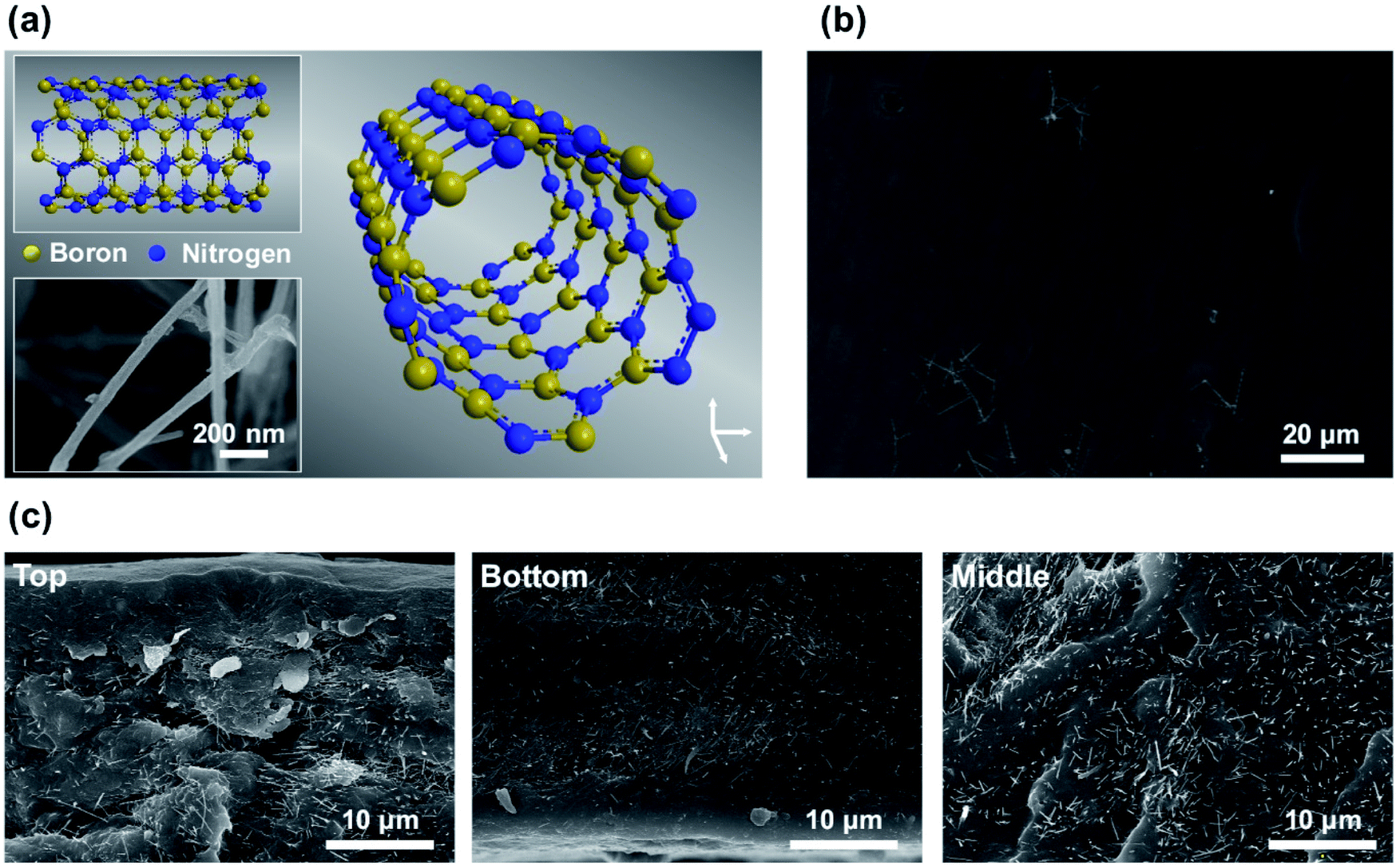 | ||
| Fig. 1 (a) Three-dimensional structure of a BNNT. Insets: two-dimensional projection and SEM image of a BNNT. (b) SEM image of the top layer of the 2.5 wt% BNNT/WPUA composite showing a smooth surface with a small amount of exposed BNNTs. (c) Cross-sectional SEM images of the composite showing well-distributed BNNTs in the WPUA matrix from the top to the bottom. | ||
Here, we report the direct formation of BNNT/WPUA polymer composite films prepared using WPUA and BNNT dispersed in aqueous solution without any additives. The resulting films showed well-dispersed BNNTs in the WPUA matrix and enhanced water resistance, mechanical and thermal properties, and chemical stability, depending on the content of BNNT fillers. Specifically, a BNNT content of 2.5 wt% was found to be optimal for enhancing the properties of the coating film, and the resulting film was confirmed to effectively prevent metal corrosion, even under extremely acidic conditions.
Results and discussion
Synthesis and structural analysis of BNNT/WPUA composites
BNNT/WPUA dispersions were prepared by mechanical agitation of BNNTs in a WPUA dispersion without additional processes or additives. As the Hildebrand solubility parameters of water and BNNT are 23 and 9.1 (cal cm−3)1/2, respectively,29 bare BNNTs are not easily dispersed in water. The dispersibility of the hydrophobic BNNTs in water can be increased by direct modification of the surface with hydrophilic groups or by adding surfactants, including block copolymers, for noncovalent functionalization of the nanotube surfaces.30–33 Surfactant absorption on BNNT surfaces forms a hydrophilic corona, which prevents sedimentation or the inhomogeneous distribution of BNNTs in aqueous solution. When WPUA is dispersed in aqueous solution, the hydrophobic acrylate segments aggregate inside and the hydrophilic polyurethane segments are exposed to the outside, similar to the self-assembled structures of surfactants. Thus, it is speculated that an excess amount of WPUA helps to disperse BNNTs in aqueous solution under vigorous stirring in the same way as surfactant absorption on BNNT surfaces. Subsequently, WPUA and BNNT/WPUA composite films were manufactured via a simple method, as follows. In an ambient chamber, WPUA or BNNT/WPUA dispersions were cast on a polytetrafluoroethylene (PTFE) substrate at a thickness of 500 μm using the doctor blade method and then dried for 2 days.Fig. 1 shows scanning electron microscopy (SEM) images of the surface and cross-sectional morphologies of a WPUA composite film containing 2.5 wt% BNNT. In this film, the BNNTs are well dispersed, with a homogenous distribution from the top to the bottom without aggregation (Fig. 1c and S1†). As shown Fig. 1b, the top surface of the film was generally smooth. The presence of a small amount of BNNTs on the top surface is likely related to the film drying process. When water in WPUA composite is evaporated during film formation, the hydrophobic acrylate segments in WPUA tend to migrate to the surface, thus facilitating contact with air.34 Therefore, hydrophobic BNNTs in the composite may also move upward during the drying process. The surface of the 2.5 wt% BNNT/WPUA film was analyzed using Fourier transform infrared (FT-IR) spectroscopy. However, the B–N (1389.9 cm−1) and B–N–B (813.3 cm−1) absorption bands of BNNTs were not observable because of the very small content of BNNTs on the surface (Fig. S2†).35,36 Compared with the WPUA composite film containing 2.5 wt% BNNTs, that containing 5 wt% BNNT had a similar surface morphology but regions with agglomerated filler were observed inside the film (Fig. S3†). This result indicated that numerous BNNTs were partially phase-separated in the WPUA matrix. When the amount of BNNTs was too high, the filler was not sufficiently dispersed and bundles formed via the hydrophobic effect. In addition, in the nonaggregated regions, the amount of filler distributed in the WPUA matrix was observed to be similar to or less than that in the 2.5 wt% BNNT/WPUA composite, thus suggesting that the efficiency of the filler was decreased.
Water resistance of BNNT/WPUA composites
The hydrophobicity and water absorption of the WPUA and BNNT/WPUA composite films were studied to evaluate the water resistance. As previously discussed, BNNTs were well dispersed in the WPUA matrix with a very small amount exposed on the surface of the film. The hydrophobic effect of BNNTs on the film surface was determined by measuring the contact angle. As shown in Fig. 2, the contact angle of the WPUA film changed from 64.1° to 70.0°, 73.1°, and 72.4° as the BNNT content of BNNTs increased to 1.25, 2.5, and 5 wt%, respectively. Similar contact angles were observed for filler contents over 2.5 wt%, indicating that most of the BNNTs were distributed inside the film as the BNNT content increased. For a film with only BNNTs on the surfaces, the contact angle can increase by 170° or more depending on the arrangement of BNNT owing to air pocket formation at the interface between the water droplet and hydrophobic BNNTs.37,38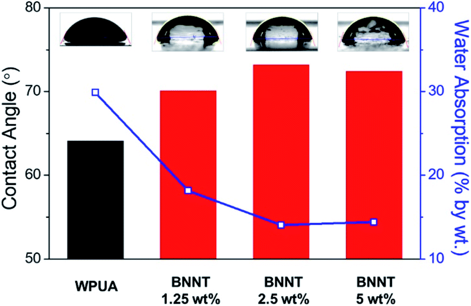 | ||
| Fig. 2 Contact angles and water absorption amounts for WPUA and BNNT/WPUA composite films. Insets: optical microscope images of contact angle measurements on each film surface. The water absorption amount was calculated after immersing the films in D.I. water for 40 h. | ||
Water absorption refers to how much water a film can hold in its internal structure, i.e., the space available for moisture to penetrate the film. To measure the effects of BNNT filler distribution on the waterproofness of the WPUA matrix and to avoid hydrophilicity differences between the outer and inner sides of the WPUA sample, the bottom of films was recoated (see the Experimental section for details). The resulting film was immersed in deionized (D.I.) water for 40 h, and then the water absorption amount was calculated (Fig. 2). The WPUA film absorbed 29.9% water by weight. In contrast, the BNNT/WPUA films showed a rapid decrease in water absorption to 14.0% at a BNNT content of 2.5 wt%. The absorption amount did not decrease further when the BNNT content was increased to 5 wt%, similar to the contact angle results. This result indicated that the filler improved the water resistance of the polymer matrix in a content-dependent manner, and 2.5 wt% BNNTs was sufficient to inhibit water absorption.
Mechanical and thermal properties of BNNT/WPUA composites
BNNTs have excellent mechanical and thermal properties, similar to CNTs, and are therefore used as reinforcement fillers in composite materials.39 The interfacial interactions between an inorganic filler and a polymer are a critical factor in determining the composite properties because these interactions contribute to transferring the load from the matrix to the filler.40 The surface area of BNNT increases as the loading quantity increases, resulting in high interconnectivity in the polymer composite and a significant increase in strength.41 Therefore, the increase amount of tensile strength of BNNT/polymer composite varies depending on the content, dispersibility, length of BNNT and intrinsic properties of polymer matrix. Lahiri reported a gradual increase in the tensile strength with the addition of BNNT from 2.67 MPa in polylactide–polycaprolactone copolymer film to 5.59 MPa for 5 wt% BNNT/polymer composites.42 When polystyrene was a matrix, Zhi reported that the tensile strength increased from 19.1 MPa to 24.4 MPa by improving the dispersity of 3 wt% of BNNTs. In the absence of a dispersant, the tensile strength was rather lowered.43 BNNT/WPUA composites also showed enhanced mechanical properties. The average tensile strengths of the WPUA and BNNT/WPUA films are shown in Fig. 3. The addition of BNNT clearly increased the fracture stress of the composite. However, the 5 wt% BNNT/WPUA film showed larger deviations and a lower stress at the minimum value. Thus, the addition of 5 wt% BNNT provides insufficient reinforcement, likely because the filler formed bundles inside the polymer matrix, as observed in the SEM images. The effective reinforcement of mechanical strength only occurs with substantial interfacial adhesion between nanotubes and the surrounding polymer.44 Li reported that agglomerates are easily formed when excess BNNTs are added to the matrix, resulting in voids and adhesion defects in the composite.39 Based on the measured tensile strengths, the optimum BNNT content to increase the fracture stress of the composite film was 1.25 wt% and the efficiency decreased when the BNNT content was greater than 2.5 wt%. At a BNNT content of 1.25 wt%, the yield stress and Young's modulus were also enhanced, indicating the elasticity of the coating material to withstand deformation (Fig. S4†).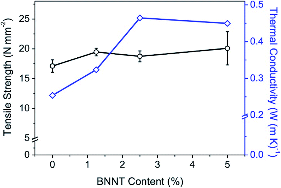 | ||
| Fig. 3 Tensile strengths and thermal conductivities of WPUA and BNNT/WPUA composite films. The tensile strength measurements were repeated on ten samples and the error bars represent the standard deviation. | ||
In discontinuous composite materials, the filler amount, shape, and dispersion are very important for improving thermal conductivity. Because BNNTs have excellent thermal conductivity, it is expected that the thermal properties of BNNT/WPUA films would gradually improve as the BNNT content increased. The effect of the BNNT content on the thermal conductivity of the BNNT/WPUA matrix was investigated (Fig. 3). As expected, the thermal conductivity increased from 0.253 to 0.464 W m K−1 when 2.5 wt% BNNTs was added. However, unexpectedly, the thermal conductivity decreased slightly when the BNNT content exceeded 2.5 wt%. As mentioned in the discussion of both the structural and mechanical properties, this observation could indicate that excess BNNTs increase voids and adhesion defects in the WPUA matrix, which interfere with heat conduction. It is also possible that the connectivity between the BNNTs in the discontinuous composite material does not improve at high BNNT contents because of the limited dispersibility. As discussed previously, increasing the BNNT content does not improve dispersibility, instead resulting in the formation of agglomerated filler bundles inside the polymer matrix.
The thermal stabilities of the BNNT/WPUA composites were estimated using derivative thermomechanical analysis (DTMA), which determines the dimensional changes of the polymer composite under controlled temperature and tensile load conditions (Fig. 4). The softening point is the temperature at which the deformation becomes severe and the performance of the coating material is lost. As the BNNT content in the WPUA matrix increased, the softening point of the coating material shifted from 62.3 to 98.4 °C. This result demonstrated that the thermal stability of the BNNT/WPUA composites continually improve as the amount of BNNTs increased. The presence of BNNTs increased the activation energy for polymer decomposition, resulting in high thermal stability.45 Increasing the BNNT content in the WPUA composite from 1.25 to 2.5 wt% resulted in a temperature difference of 6.6 °C. In the case of 5 wt% BNNT/WPUA, the observed change was not proportional to the BNNT content, with the softening point increasing 6.4 °C relative to that of 2.5 wt% BNNT/WPUA. This phenomenon corresponded well to the low enhancement efficiencies for the mechanical and thermal properties at excess filler contents.
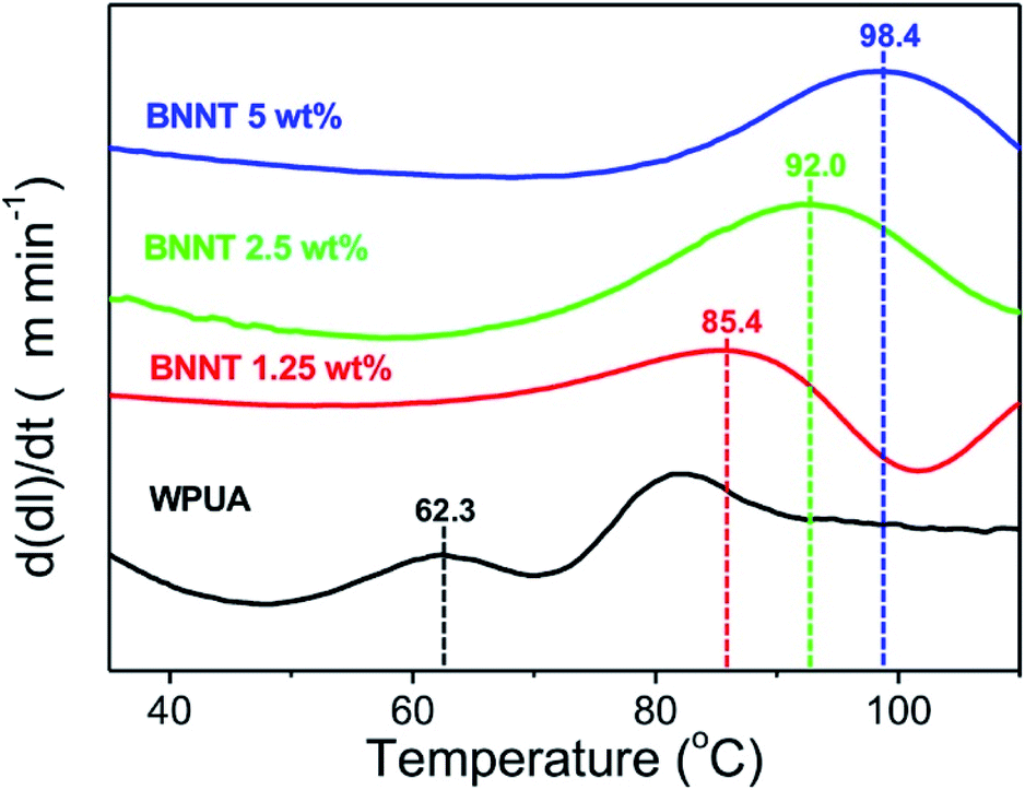 | ||
| Fig. 4 DTMA measurements for WPUA and BNNT/WPUA composite films. | ||
Chemical resistance of BNNT/WPUA composites
To evaluate the chemical stability, WPUA and BNNT/WPUA composites were coated on both sides of a Zn plate and then immersed in saline solution and hydrochloric acid solution to observe the degree of corrosion. The open circuit potential (OCP) variation implied the initiation and propagation of the corrosion.46 Relatively stable OCP values represented an electrochemical steady state on the electrode surface. Fig. 5a shows the OCP values of the composite coatings as a function of time recorded in the 3.5 wt% NaCl solution for 10 min. The corrosion potential at 10 min shifted gradually towards the anodic direction in the sequence of 2.5% BNNT (−0.996 V) > 1.25% BNNT (−1.027 V) > 5% BNNT (−1.048 V) > WPUA (−1.070 V) > bare Zn (−1.075 V). This is due to anodic protection which inhibited to dissolve Zn from coating and excessive quantities of BNNT as 5% reduced the properties of corrosion protection compared to optimum quantity as 2.5% BNNT. The potentiodynamic polarization curves were detected after soaking into saline solution for 30 min (Fig. 5b). The hydrogen generated from H2O at the potential below −1.3 V as described by the following equation.47| 2H2O + 2e− → 2OH− + H2 | (1) |
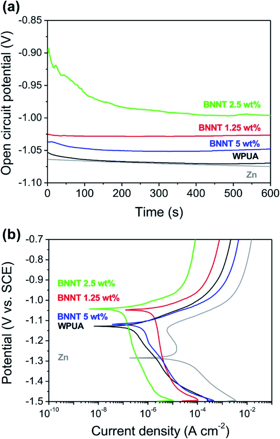 | ||
| Fig. 5 (a) Open-circuit potential (OCP) versus the immersing time in 3.5 wt% NaCl solution and (b) the potentiodynamic polarization curves of bare Zn and WPUA, 1.25%, 2.5%, 5% BNNT/WPUA coated Zn plates. | ||
The potential as −1.3 V to −1.2 V represented oxygen consumption as shown in eqn (2) and (3).47
| O2 + H2O + 2e− → HO2− + OH− | (2) |
| HO2− + H2O + 2e− → 3OH− | (3) |
In these respects, peaks below −1.2 V shows the mixed potential of the hydrogen evolution reaction and the anodic dissolution. The corrosion potential (Ecorr) of bare Zn, WPUA coated Zn, 1.25%, 2.5%, 5% BNNT/WPUA coated Zn were −1.284 V, −1.128 V, −1.048 V, −1.043 V and −1.119 V, respectively. The existence of upward shift in Ecorr in the more positive direction means that the earlier inferences of corrosion resistance due to its WPUA and WPUA/BNNT coating. It referred that WPUA assisted to resist the corrosion compared to bare Zn plate. Furthermore, 2.5 wt% BNNT proliferated the corrosion protection property of WPUA.
The anti-corrosion performance of the coatings was also demonstrated by the EIS measurement (Fig. 6). In low-frequency region, the corrosion resistance between anodic and cathodic could be measured by impedance modulus (|Z|). The impedance modulus of 2.5% BNNT/WPUA coated Zn had highest value at 0.1 Hz (Fig. 6a) which was arisen from less possibility for corrosion to occur. The semicircle curve in Nyquist plot indicated the resistance from the charge transfer at the electrode surface. The diameter of impedance spectra represented the polarization resistance. The semicircle diameters were in the sequence of 2.5% BNNT (43![[thin space (1/6-em)]](https://www.rsc.org/images/entities/char_2009.gif) 260 Ω) > 1.25% BNNT (5860 Ω) > 5% BNNT (4907 Ω) > WPUA (2995 Ω) > bare Zn (22.04 Ω) (Fig. 6b). The significant enhancement in anti-corrosion performance was detected when 2.5% BNNT/WPUA was coated due to the increase in charge transfer resistance. It was well corresponded to the OCP results and the potentiodynamic polarization plots.
260 Ω) > 1.25% BNNT (5860 Ω) > 5% BNNT (4907 Ω) > WPUA (2995 Ω) > bare Zn (22.04 Ω) (Fig. 6b). The significant enhancement in anti-corrosion performance was detected when 2.5% BNNT/WPUA was coated due to the increase in charge transfer resistance. It was well corresponded to the OCP results and the potentiodynamic polarization plots.
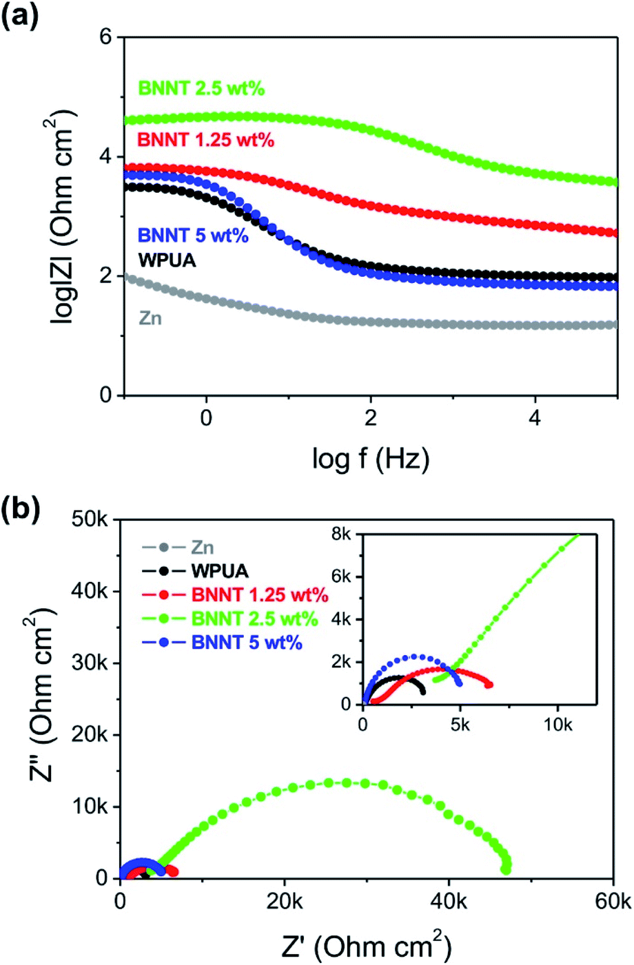 | ||
| Fig. 6 (a) Bode plots and (b) Nyquist plots in 3.5% NaCl solution for bare Zn and WPUA, 1.25%, 2.5%, 5% BNNT/WPUA coated Zn plates. | ||
In order to demonstrate expandability and emphasize the importance of coating, the corrosion tests according to the immersion time into acid solution which rapidly dissolved the Zn metal plate were conducted.
After removing residual solvent from the surface of the films, the time-dependent weight loss was measured. Owing to the inherent corrosion resistance of WPUA, the WPUA film without BNNTs gradually swelled in 10 vol% hydrochloric acid over 150 h, and the hydrogen generation reaction occurred slowly on the Zn surface, even after approximately 950 h (Fig. S5†). It was difficult to determine the chemical stabilities of the BNNT/WPUA composites because the presence of BNNTs improved the barrier properties by lowering the absorption of the film (Fig. 2). Hence, we conducted corrosion experiments under harsh conditions (30 vol% hydrochloric acid solution) to confirm the effects induced by BNNT fillers.
As shown in Fig. 7a, the Zn plate coated with pure WPUA was rapidly corroded and the coating disappeared within 1 h. In contrast, the Zn plate coated with 1.25 wt% BNNT/WPUA showed a slight weight loss after 4 days, but the total weight loss remained less than 6% until 10 days. The Zn plate coated with 2.5 wt% BNNT/WPUA showed greater stability, with corrosion only beginning after 6 days. This behavior was consistent with the water absorption results, which showed that the extent of swelling for the BNNT/WPUA films was only half that for the WPUA film. However, an obvious decrease in corrosion resistance was observed for the 5 wt% BNNT/WPUA coating. After 3 days, the Zn plate was corroded, with a damaged part appearing in the coating layer. When the Zn plate reacts with the hydrochloric acid, the relatively rapid generation of hydrogen gas can rupture the coating material if there are defects such as voids within the polymer matrix. We assume that corrosion was accelerated because the acid solution quickly reached the Zn plate through defects in the coating layer. This result provides convincing evidence that the addition of excess BNNTs to the WPUA matrix promotes the formation of voids in the composite and results in unstable adhesion.41 in this respect, the optimum content of BNNT fillers in the WPUA matrix was between 1.25 and 2.5 wt%.
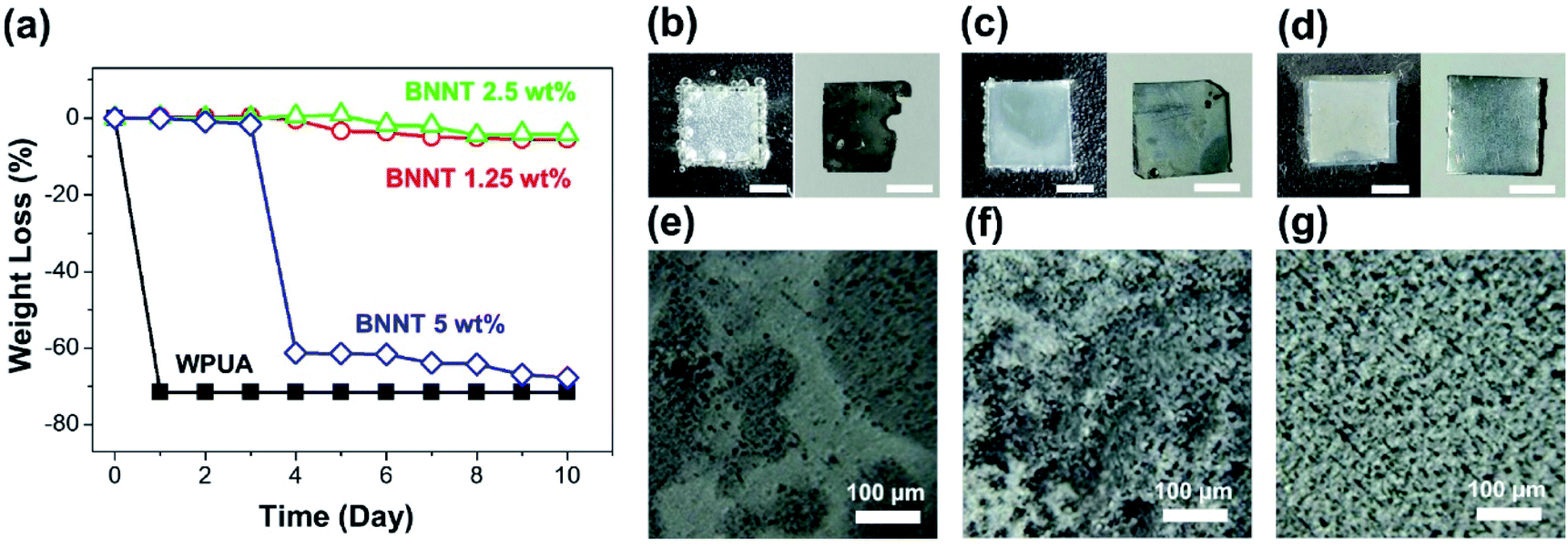 | ||
| Fig. 7 Corrosion resistance of WPUA and BNNT/WPUA-coated Zn plates immersed in 30 vol% hydrochloric acid solution. (a) Weight loss measurements for coated Zn plates. (b–d) Photographs of coated Zn plates (b) no coating, (c) WPUA coated, and (d) 2.5 wt% BNNT/WPUA coated in HCl solution (left) and with the coating peeled off (right) after corrosion tests for 15 s, 2 min, 5 min, respectively. Scale bars are 5 mm. (e–g) SEM images of Zn plates with the coating peeled off after corrosion tests (e) no coating, (f) WPUA coated, and (g) 2.5 wt% BNNT/WPUA coated. | ||
The effects of the BNNT filler on acid stability were easily observed. When the bare Zn plate was soaked in 30% hydrochloric acid, the hydrogen evolution reaction was immediately initialized (Fig. 7b). A portion of the Zn plate exposed to hydrochloric acid dissolved within 1 min. The WPUA-coated Zn plate showed a small amount of hydrogen generation at the edge of the Zn plate (Fig. 7c). After 2 min, the Zn plate with the WPUA coating peeled off showed relatively little deformation on the surface and edges. However, when the Zn plate was coated with a 2.5 wt% BNNT/WPUA film, hydrogen generation did not proceed within 5 min (Fig. 7d). To evaluate the corrosion resistance in more detail, the surface roughnesses of the acid-treated Zn plates were observed by SEM. The corroded bare Zn specimen showed a smooth and discolored surface instead of the roughness of the Zn surface before corrosion (Fig. 7e). As shown in Fig. 7f, distinct rough and smooth surfaces could be distinguished on the slightly corroded WPUA-coated Zn plate. However, the surface of the Zn plate with the 2.5 wt% BNNT/WPUA coating seemed to be undamaged and similar to the initial Zn plate (Fig. 7g).
Corrosion-resistant thin film coatings on circuit boards
Finally, we tested the corrosion resistance of the 2.5 wt% BNNT/WPUA material by coating a circuit board, which consists of a copper alloy on a plastic substrate and has an irregular surface. Instead of using a doctor blade, a minimal thin coating was applied by drop-casting the WPUA or WPUA/BNNT dispersion onto the circuit board several times. After drying, the thicknesses of the WPUA and WPUA/BNNT coatings were 100 and 80 μm, respectively, as measured using vernier calipers. The circuit board without a coating was corroded within 10 min in a 65 vol% nitric acid solution, and the color of the board changed from green to brown (Fig. S6†). To observe the corrosiveness of the copper alloy over time, corrosion experiments were conducted by immersing the circuit boards in a 30 vol% nitric acid solution (Fig. 8). After 1 h, the noncoated circuit board began to corrode and the copper alloy on the board fragmented and spread into the solution (Fig. 8 and S7†). After 5 h, the copper alloy continued to fragment and the board also became discolored. The circuit board coated with WPUA did not corrode within 2 h because of the intrinsic acid resistance of WPUA. As seen in the corrosion test with Zn plates, the copper inside the WPUA coating gradually corroded and hydrogen gas was generated after 3 h. Subsequently, corrosion proceeded rapidly because of the loss of the function of the coating. In the case of the 2.5 wt% BNNT/WPUA-coated circuit board, no corrosion was observed, even after 5 h. The color of the coating layer turned slightly white around the center of the circuit board with a height difference. A small amount of swelling may occur at the curved part of the coating film, but it does not seem to damage the interior of the coating. Even after a week, the 2.5 wt% BNNT/WPUA-coated circuit board was not corroded and hydrogen generation was not observed under these harsh conditions.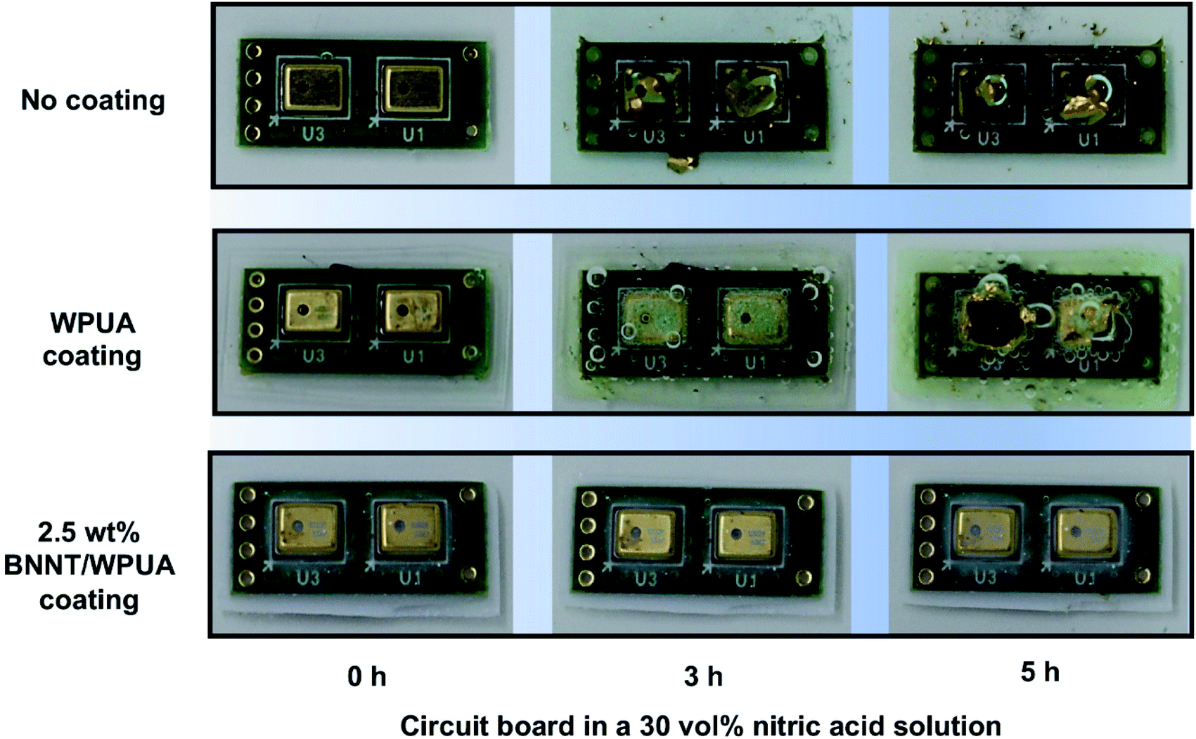 | ||
| Fig. 8 Photographs of noncoated, WPUA-coated, and 2.5 wt% BNNT/WPUA-coated circuit boards in a 30 vol% nitric acid solution over time. Corrosion of the 2.5 wt% BNNT/WPUA-coated circuit board did not proceed even after a week. | ||
Conclusions
BNNTs are an excellent inorganic filler for WPUA owing to their chemical and thermal stability. In this work, to maintain the advantageous water dispersibility and environmental friendliness of WPUA, fillers were added without using organic solvents or additives. The BNNT/WPUA composites had well-dispersed fillers and showed enhanced water resistance as coating materials. With respect to the mechanical properties of the BNNT/WPUA composite film, the addition of 1.25 wt% BNNTs reinforced the polymer matrix with an increase in the fracture stress, yield stress, and Young's modulus. The optimal content of 2.5 wt% BNNTs improved the thermal properties of the composite film. Furthermore, the composite films with 1.25 to 2.5 wt% BNNTs showed enhanced chemical resistance, whereas an excess BNNT content of 5 wt% showed a lower enhancement efficiency. These results demonstrated that the WPUA coating material with 2.5 wt% BNNT fillers has excellent durability in harsh environments. These water-based eco-friendly coating materials may be beneficial in various industries such as construction, electronic devices, and automobiles.Experimental
Materials
WPUA (AU-1000, acrylate Tg = −28.4 °C) was purchased from APEC, Ltd. BNNT was purchased from NAiEEL Technology, Co. Zn plates (MRS86086, 20 cm × 20 cm) were purchased from Miraes.Characterization
Thin films were formed using a doctor blade (MTI Korea, 10 cm wide). SEM images were obtained using field emission scanning electron microscope (Hitachi, S-4800) at an acceleration voltage of 10 kV. The SEM samples were coated with Pt using a sputter coater. The bonding states in the WPUA-containing BNNTs were analyzed by FT-IR spectroscopy (Bruker, Alpha) in the range of 1000–4000 cm−1. The hydrophilicities of WPUA and BNNT/WPUA films were determined using a contact angle meter and optical microscope images (SEO Korea, PHIENIC3). The mechanical properties were measured using a universal testing machine (TnDorf, TD-U01) at a loading rate of 50 mm min−1 with an initial length of 10 mm. The terminal values of the mechanical strength of the composite films were the average of 10 specimens. Thermal conductivities were measured using a Trident instrument (C-Therm). Thermomechanical analysis curves were obtained from 25 to 250 °C at a heating rate of 10 °C min−1 in a nitrogen atmosphere (Hitachi, TMA7100). The effects of BNNT content on the thermal conductivities of the composite films were evaluated using DTMA. Corrosion analysis for bare and coated Zn was done using a potentiostat (Autolab, PGSTAT302N) in saline solution.Preparation of BNNT/WPUA composites
In a typical procedure, the 2.5 wt% BNNT/WPUA composite was prepared as follows. BNNT (0.1 g) was added in WPUA aqueous solution (10 ml, WPUA 40 wt%) in a 20 ml vial with a magnetic stirrer. The solution was stirred for two hours at room temperature. BNNT/WPUA composite films with thicknesses of approximately 500 μm were simply fabricated using the doctor blade method. The doctor blade was placed vertically on the surface of the PTFE substrate, which was already covered with a BNNT/WPUA solution. The blade was then dragged at a fast speed to move the mixture across the gap between the doctor blade and the substrate. The prepared films had dimensions of 10 mm × 20 mm and were dried for 2 days at room temperature. For the water absorption experiments, the fabricated film was detached from the substrate and then the interior surface was recoated with the WPUA or BNNT/WPUA solution to avoid hydrophilicity differences between the outer and inner sides of the WPUA sample.Preparation of WPUA and BNNT/WPUA-coated Zn plates and circuit boards
The WPUA or BNNT/WPUA mixture was drop-cast to completely cover the edges of the Zn plate or circuit board, which was placed on a PTFE substrate. After drying for 2 days, the WPUA or BNNT/WPUA mixture was also drop-cast on the other side of the Zn plate or circuit board and dried for 2 days.Polarization resistance test
The WPUA or BNNT/WPUA mixture was coated to Zn plate (10 × 30 × 0.3 mm) by the above preparation method. Polarization resistance and impedance at open circuit voltage test was performed in 3.5% NaCl solution. Prior to the measurement, each sample was immersed in the NaCl solution for 30 min until a stable open circuit potential was reached. Electrochemical impedance spectroscopy (EIS) was performed in a frequency range from 100 kHz to 0.1 Hz using PGSTAT302N. Three electrodes were used, containing a counter-electrode (Pt mesh), reference-electrode (saturated calomel electrode), working electrode (bare Zn and coated Zn). The potentiodynamic measurements were taken between −1.5 and −0.7 V at a scan rate of 1 mV s−1.Calculation of water absorption and weight loss
The water resistance of the composite films was determined based on the amount of absorbed water. The initial weight of the composite film is denoted WI. The prepared films were immersed in D.I. water and the water adsorption amount was evaluated using the weight change according to the immersion time (Wt). Before measuring the weight change in the samples, the surface of was wiped. The water absorption amount (%) was calculated follows.| Water absorption (%) = (Wt − WI)/WI × 100 |
The corrosion protection abilities of the BNNT/WPUA composites in an acidic environment were measured using a method similar to that for water absorption. The initial weight of the BNNT/WPUA-coated Zn plate is denoted WI. The prepared samples were immersed in a 10 or 30 vol% HCl solution. The weight change arising from metal corrosion at different immersion times is denoted Wt. The weight loss (%) was calculated as described above.
Conflicts of interest
There are no conflicts to declare.Acknowledgements
This research was supported by Nano Material Technology Development Program through the National Research Foundation of Korea (NRF) funded by Ministry of Science and ICT (No. 2016M3A7B4910458 and 2018M3A7B4070990); National Research Foundation of Korea (NRF) grant funded by the Korea Government (MSIT) (No. 2020R1A2C2103137 and 2020R1F1A1076359); the Korea Institute of Energy Technology Evaluation and Planning (KETEP) and the Ministry of Trade, Industry & Energy (MOTIE) of the Republic of Korea (No. 20181110200070); Materials, Components & Equipment Research Program funded by the Gyeonggi Province.Notes and references
- J. Zhang, H. Ren, P. Chen, Z. Zhang and C. Hu, Polymer, 2019, 180, 121690 CrossRef CAS.
- H. Honarkar, J. Dispersion Sci. Technol., 2018, 39, 50–7516 CrossRef.
- S. S. Panda, B. P. Panda, S. K. Nayak and S. Mohanty, Polym.-Plast. Technol. Eng., 2018, 57, 500–522 CrossRef CAS.
- X. Zhou, Y. Li, C. Fang, S. Li, Y. Cheng, W. Lei and X. Meng, J. Mater. Res., 2015, 31, 708–722 Search PubMed.
- H. Xu, F. Qiu, Y. Wang, W. Wu, D. Yang and Q. Guo, Prog. Org. Coat., 2012, 73(1), 47–53 CrossRef CAS.
- M. B. Kale, Z. Luo, X. Zhang, D. Dhamodharan, N. Divakaran, S. Mubarak, L. Wu and Y. Xu, Polymer, 2019, 170, 43–53 CrossRef CAS.
- S. K. Lee and B. K. Kim, J. Colloid Interface Sci., 2009, 336(1), 208–214 CrossRef CAS PubMed.
- L. Wu, B. You and D. Li, J. Appl. Polym. Sci., 2002, 84(8), 1620–1628 CrossRef CAS.
- H. T. Lee and C. C. Wang, J. Polym. Res., 2005, 12(4), 271–277 CrossRef CAS.
- J. Xu, Y. Jiang, F. Qiu, Y. Dai, D. Yang, Z. Yu and P. Yang, Polym. Bull., 2018, 75(10), 4713–4734 CrossRef CAS.
- C. F. J. Kuo, M. Y. Dong and C. P. Yang, Text. Res. J., 2020 DOI:10.1177/0040517520975660.
- G. Fei, H. Geng, H. Wang, X. Liu, Y. Liao, Y. Shao and M. Wang, Polymers, 2019, 11(12), 1922 CrossRef CAS PubMed.
- Y. J. Deng, C. Zhou, M. Y. Zhang and H. X. Zhang, Prog. Org. Coat., 2018, 122, 239–247 CrossRef CAS.
- H. Wang, S. Qin, X. Yang, G. Fei, M. Tian, Y. Shao and K. Zhu, Chem. Eng. J., 2018, 351, 939–951 CrossRef CAS.
- Y. Yin, Y. Muhammad, X. Zeng, J. Yang, J. Li, S. Yang and S. Subhan, Prog. Org. Coat., 2018, 125, 234–241 CrossRef CAS.
- C. Yu, J. Zhang, W. Tian, X. Fan and Y. Yao, RSC Adv., 2018, 8, 21948–21967 RSC.
- J. P. Yang, Z. K. Chen, Q. P. Feng, Y. H. Deng, Y. Liu, Q. Q. Ni and S. Y. Fu, Composites, Part B, 2012, 43, 22–26 CrossRef.
- X. Q. Li, C. Y. Wang, Y. Cao and G. X. Wang, Chem.–Asian J., 2018, 13, 2742–2757 CrossRef CAS PubMed.
- S. B. Tu, Q. Jiang, X. X. Zhang and H. N. Alshareef, ACS Nano, 2018, 12, 3369–3377 CrossRef CAS PubMed.
- O. P. Koc, S. B. Acar, T. Uyar and M. A. Tasdelen, Polym. Bull., 2018, 75, 1–11 CrossRef.
- Y. Su, J. J. Li and G. J. Weng, Carbon, 2018, 137, 222–233 CrossRef CAS.
- J. Dalal, S. Lather, A. Gupta, S. Dahiya, A. S. Maan, K. Singh, S. K. Dhawan and A. Ohlan, Compos. Sci. Technol., 2018, 165, 222–230 CrossRef CAS.
- J. Salvetat, G. A. D. Briggs, J. Bonard, R. R. Bacsa, A. J. Kulik, T. Stöckli, N. A. Burnham and L. Forró, Phys. Rev. Lett., 1999, 82, 944–947 CrossRef CAS.
- A. D. S. MacWilliams, C. A. D. L. Reyes, L. Liberman, S. Ergülen, Y. Talmon, M. Pasquali and A. A. Marti, Nanoscale Adv., 2019, 1, 1096–1103 RSC.
- T. Terao, C. Y. Zhi, Y. Bando, M. Mitome, C. C. Tang and D. Golberg, J. Phys. Chem. C, 2010, 114, 4340–4344 CrossRef CAS.
- C. Zhi, Y. Bando, T. Terao, C. Tang, H. Kuwahara and D. Golberg, Adv. Funct. Mater., 2009, 19(12), 1857–1862 CrossRef CAS.
- D. Golberg, Y. Bando, K. Kurashima and T. Sato, Scr. Mater., 2001, 44, 1561–1565 CrossRef CAS.
- C. R. Dean, A. F. Young, I. Meric, C. Lee, L. Wang, S. Sorgenfrei, K. Watanabe, T. Taniguchi, P. Kim, K. L. Shepard and J. Hone, Nat. Nanotechnol., 2010, 5, 722 CrossRef CAS PubMed.
- M. Mutz, E. Eastwood and M. D. Dadmun, J. Phys. Chem. C, 2013, 117, 13230–13238 CrossRef CAS.
- S. W. Jeon, S. H. Kang, J. C. Choi and T. H. Kim, Polymers, 2019, 11(4), 582 CrossRef PubMed.
- C. H. Lee, D. Zhang and Y. K. Yap, J. Phys. Chem. C, 2012, 116(2), 1798–1804 CrossRef CAS.
- A. D. S. McWilliams, A. Carlos, L. Liberman, S. Ergülen, Y. Talmon, M. Pasquali and A. A. Martí, Nanoscale Adv., 2019, 1(3), 1096–1103 RSC.
- J. Yu, Y. Chen and B. M. Cheng, Solid State Commun., 2009, 149, 763–766 CrossRef CAS.
- G. A. Alvarez, M. Fuensanta, V. H. Orozco, L. F. Giraldo and J. M. Martín-Martínez, Prog. Org. Coat., 2018, 118, 30–39 CrossRef CAS.
- W. Mickelson, S. Aloni, W. Q. Han, J. Cumings and A. Zettl, Science, 2003, 300, 467 CrossRef CAS PubMed.
- J. Chen, M. A. Hamon, H. Hu, Y. S. Chen, A. M. Rao, P. C. Eklund and R. C. Haddon, Science, 1998, 282, 95 CrossRef CAS PubMed.
- L. B. Boinovich, A. M. Emelyanenko, A. S. Pashinin, C. H. Lee, J. Drelich and Y. K. Yap, Langmuir, 2012, 28, 1206–1216 CrossRef CAS PubMed.
- L. H. Li and Y. Chen, Langmuir, 2010, 26, 5135–5140 CrossRef CAS PubMed.
- A. H. Barber, S. R. Cohen, A. Eitan, L. S. Schadler and H. D. Wagner, Adv. Mater., 2006, 18, 83–87 CrossRef CAS.
- H. Guo, M. L. Minus, S. Jagannathan and S. Kumar, ACS Appl. Mater. Interfaces, 2010, 2, 1331–1342 CrossRef CAS PubMed.
- A. A. Mamedov, N. A. Kotov, M. Prato, D. M. Guldi, J. P. Wicksted and A. Hirsch, Nat. Mater., 2002, 1, 190–194 CrossRef CAS PubMed.
- D. Lahiri, F. Rouzaud, T. Richard, A. K. Keshri, S. R. Bakshi, L. Kos and A. Agarwal, Acta Biomater., 2010, 6, 3524–3533 CrossRef CAS PubMed.
- C. Y. Zhi, Y. Bando, W. L. Wang, C. C. Tang, H. Kuwahara and D. Golberg, J. Mater. Res., 2006, 21, 2794–2800 CrossRef CAS.
- L. Li, Y. Chen and Z. H. Stachurski, Prog. Nat. Sci., 2013, 23, 170–173 CrossRef.
- J. Joy, E. George, S. Thomas and S. Anas, New J. Chem., 2020, 44, 4494–4503 RSC.
- M. C. Zhao, M. Liu, G. L. Song and A. Atrens, Corros. Sci., 2008, 50, 3168–3178 CrossRef CAS.
- Y. Meng, L. Liu, D. Zhang, C. Dong, Y. Yan, A. A. Volinsky and L. Wang, Initial formation of corrosion products on pure zinc in saline solution, Bioact. Mater., 2019, 4, 87–96 CrossRef PubMed.
Footnotes |
| † Electronic supplementary information (ESI) available. See DOI: 10.1039/d1ra00873k |
| ‡ These authors contributed equally to this work. |
| This journal is © The Royal Society of Chemistry 2021 |