 Open Access Article
Surface modification of Ni-rich LiNi0.8Co0.1Mn0.1O2 with perovskite LaFeO3 for high voltage cathode materials
Hong Ki Kima,
Hyeong Seop Kanga,
P. Santhoshkumarb,
Jae Woo Parka,
Chang Won Hoa,
Gyu Sang Sima and
Chang Woo Lee *ab
*ab
aDepartment of Chemical Engineering (Integrated Engineering), College of Engineering, Kyung Hee University, 1732 Deogyeong-daero, Giheung, Yongin, Gyeonggi 17104, South Korea. E-mail: cwlee@khu.ac.kr; Fax: +82-31-204-8114; Tel: +82-31-201-3825
bCenter for the SMART Energy Platform, College of Engineering, Kyung Hee University, 1732 Deogyeong-daero, Giheung, Yongin, Gyeonggi 17104, South Korea
First published on 18th June 2021
Abstract
Ni-rich LiNi0.8Co0.1Mn0.1O2 (NCM811) is regarded as a potential cathode material due to its higher capacity. However, the severe capacity fading which occurs above 4.2 V vs. Li/Li+ needs to be addressed to enhance the electrochemical performance. Herein, we report the surface modification of NCM811 cathodes with a perovskite material, i.e., lanthanum iron oxide (LaFeO3), which has drawn attention for various research areas due to its non-toxicity, electric conductivity, chemical stability, and low cost and systematically investigate the influence of the LaFeO3 coating on NCM811. The LaFeO3 coating layer significantly protects the cathode material from corrosion due to the HF formation and restrains the dissolution of other ions into liquid electrolyte during high voltage charge–discharge processes. Even after 80 cycles, 0.5 wt% LaFeO3-coated NCM811 cathode material shows about 13% higher cycling stability when compared to the bare NCM811 and other ratios of coated materials. Furthermore, the 0.5 wt% LaFeO3-coated NCM811 delivers excellent rate capability and demonstrates improved structural stability at 4.6 V vs. Li/Li+ under high voltage conditions with Ni-rich cathode active materials.
1. Introduction
Lithium ion batteries (LIBs) with a high energy density and power density have been used for electric vehicles (EVs) and hybrid electric vehicles (HEVs) as renewable energy systems.1–4 They are also anticipated to provide electrochemical energy storage for solar energy and wind power sources.5 A high capacity retention and high energy density are the main points for making commercialized LIBs in electric vehicles.6 Improving the electrode active material is a way to achieve these purposes, especially for cathode active materials. In order to improve the cathode materials, many efforts are being made such as changing the structure or synthesizing materials.7 Among the various materials used in LIBs, high nickel (Ni) compounds such as LiNi1−x−yCoxMnyO2 (NCM, 1 − x − y ≥0.5) are promising materials for EVs and HEVs.8,9 The high Ni content in NCM helps to result in a high capacity and the content of manganese (Mn) increases the structural stability. Furthermore, the content of cobalt (Co) plays a role in improving the rate capability. In particular, NCM811 is one of the most promising Ni-rich cathode materials which have a higher capacity than conventional LiCoO2 cathode material.10,11However, some factors like thermal stability and structural change induce performance degradations in Ni-rich layered oxide NCM811 materials. At high voltages, unstable Ni4+ on the surface of the cathode materials is reduced to Ni2+ and is accompanied by the formation of a spinel phase or rock salt phase.12–15 This structural rearrangement hinders the diffusion of lithium ions and leads to rapid capacity fading. In addition, NCM811 cathode materials are charged at high voltage (≥4.5 V vs. Li/Li+), causing oxidation of the electrolyte.16,17 The decomposition of organic electrolytes produces a variety of by-products.18 As shown in eqn (1) and (2), these by-products form a cathode electrolyte interface (CEI) film on the cathode material surface, which leads to decreasing capacity and rate capability because of low ionic and electric conductivities.19
| LiPF6 + 4H2O → LiF + PO4H3 + 5HF | (1) |
| DEC + LiPF6 → C2H5OCOOPF4 + C2H4 + HF + LiF | (2) |
From the above factors, it is important to prevent the side reactions between the cathode electrode material and electrolyte. To prevent such degradation, various methods have been adopted including morphology control, surface modification, and substitution of elements.20 Among the various methods, surface modification is considered as the most effective method for improving the electrochemical performances of Ni-rich cathode material. There are a lot of inorganic materials e.g., LiYO2, SiO2, WO3, Li2MnO3, Li3PO4, CaO, etc., which have been reported to be used as coating materials.21–25 Certain requirements must be met when choosing candidates such as: (1) the coating materials need good electrical conductivity which facilitates the electron transfer rate and (2) an HF scavenger, it should be able to improve the high voltage performance of LIBs by suppressing the interfacial side reactions between electrode and electrolyte.26,27
Recently, ABO3-type perovskite oxides have received much attention because of their physical/chemical properties including high electric/ionic conductivity and good structural stability.28–32 In particular, LaFeO3 is a non-toxic material and has good dielectric properties which can be used in water treatment, solar cells, photocatalysis, and biosensors.33,34 The structural properties of LaFeO3 with oxygen vacancies increase the ionic conductivity by enabling charge transfer.35
In this study, we've adopted LaFeO3 with the above-mentioned intrinsic merits of structural and thermal stability to make a coating layer on the surface of NCM811 and diagnosed its validity of improving the electrochemical performances, particularly at high voltages. This coating material has been expected to increase the ionic and electric conductivities and could offer protection from side reactions between the electrode and electrolyte at high voltages. Moreover, it could be an environmentally friendly way to improve battery performances. The LaFeO3-coated NCM811 cathode materials were synthesized by a wet chemical method and we investigated the physical and electrochemical properties of the as-prepared electrode materials.
2. Experimental
2.1. Synthesis of LaFeO3-coated NCM811
LaFeO3-coated NCM811 electrode materials were fabricated by a wet chemical synthesis technique. To prepare the coating solution, the proper stoichiometric ratio of precursor materials such as lanthanum nitrate hexahydrate (Junsei Chemical Co., Ltd, La(NO3)3·6H2O, 98.0%) and iron nitrate nonahydrate (Dae-Jung Co., Ltd, Fe(NO3)3·9H2O, 98.0%) were dissolved in ethyl alcohol (Dae-Jung Co., Ltd, 99.9%) under stirring. Subsequently, commercially available NCM811 (L&F chemicals co., Ltd) cathode active material was added into the above-prepared solution at a specific weight ratio and the solution was maintained at 60 °C under stirring. Ethyl alcohol was then evaporated from the above-mixed solution. The resultant products were collected and dried in a convection oven at 120 °C for 5 h and finally, the product was sintered at 600 °C for 2 h in air to obtain a series of LaFeO3-coated NCM811 cathode active materials. The coating ratios of 0.5 and 1.0 wt% LaFeO3-coated NCM811 were compared to bare NCM811.2.2. Materials characterizations
X-ray diffraction (XRD, D8 Advance, Bruker) using Cu-Kα radiation was employed to identify the crystalline structure of the bare and LaFeO3-coated samples in the 2θ range of 10° to 80° at a scanning rate of 6° min−1 at room temperature. Fourier transform infrared spectroscopy (FT-IR, Spectrum One System, Perkin-Elmer) was used to confirm the formation of the coating layer of the sample with a wide range of wavenumbers. To investigate the electronic valance state and surface elemental compositions of bare and coated materials, a X-ray photoelectron spectroscopy system (XPS, Multilab2000, Thermo VG Scientific System) with a monochromatic Al X-ray source (Al-Kα line, 1486.6 eV) was utilized. The morphologies and intrinsic properties of the bare and LaFeO3-coated Ni-rich NCM811 cathode materials were evaluated by field-emission scanning electron microscopy (FE-SEM, LEO SUPRA 55, Carl Zeiss) and field-emission transmission electron microscopy (FE-TEM, JEM-2100F, JEOL).2.3. Electrochemical measurements
The working electrode was fabricated by blending the bare or LaFeO3-coated NCM811 electrode materials, Denka black conductive agent, and polyvinylidene difluoride (PVdF) at a weight ratio of 90![[thin space (1/6-em)]](https://www.rsc.org/images/entities/char_2009.gif) :
:![[thin space (1/6-em)]](https://www.rsc.org/images/entities/char_2009.gif) 5
5![[thin space (1/6-em)]](https://www.rsc.org/images/entities/char_2009.gif) :
:![[thin space (1/6-em)]](https://www.rsc.org/images/entities/char_2009.gif) 5. In sequence, the powder mixture was dispersed in N-methyyl-2-pyrrolidone (NMP) to form a homogeneous slurry. The prepared slurry was laminated onto aluminium (Al) foil, which acts as a current collector, and the prepared electrode was allowed to dry in an air atmosphere for 12 h at room temperature and then dried in a convection oven at 120 °C for 5 h. Then, the prepared electrodes were cut into a disc shape having a diameter of 14 mm and dried again at 120 °C for 5 h under vacuum to remove the residual solvents. After drying, the electrodes were assembled into a CR2032-type coin cell in an Ar filled glove box (KIYON, Korea) to evaluate the electrochemical performance of the bare and LaFeO3-coated NCM811 cathode materials using a lithium metal sheet as the counter electrode and Celgard 2340 as the separator. The electrolyte used was 1 M LiPF6 dissolved in a mixture of ethylene carbonate and diethyl carbonate (EC/DEC, 1
5. In sequence, the powder mixture was dispersed in N-methyyl-2-pyrrolidone (NMP) to form a homogeneous slurry. The prepared slurry was laminated onto aluminium (Al) foil, which acts as a current collector, and the prepared electrode was allowed to dry in an air atmosphere for 12 h at room temperature and then dried in a convection oven at 120 °C for 5 h. Then, the prepared electrodes were cut into a disc shape having a diameter of 14 mm and dried again at 120 °C for 5 h under vacuum to remove the residual solvents. After drying, the electrodes were assembled into a CR2032-type coin cell in an Ar filled glove box (KIYON, Korea) to evaluate the electrochemical performance of the bare and LaFeO3-coated NCM811 cathode materials using a lithium metal sheet as the counter electrode and Celgard 2340 as the separator. The electrolyte used was 1 M LiPF6 dissolved in a mixture of ethylene carbonate and diethyl carbonate (EC/DEC, 1![[thin space (1/6-em)]](https://www.rsc.org/images/entities/char_2009.gif) :
:![[thin space (1/6-em)]](https://www.rsc.org/images/entities/char_2009.gif) 1 by volume). All fabricated coin cells were rested at room temperature for about 12 h for the aging process prior to analysing the electrochemical performance. The electrochemical performances of each coin cell made by bare and LaFeO3-coated NCM811 cathode materials were evaluated by cycling on a battery testing system (BaTester 05001, HTC Instruments) in the voltage range of 3.0–4.6 V with different current rates. Electrochemical impedance spectroscopy (EIS) was performed by a multichannel electrochemical analyzer (COMPACTSTAT, IVUIM technologies).
1 by volume). All fabricated coin cells were rested at room temperature for about 12 h for the aging process prior to analysing the electrochemical performance. The electrochemical performances of each coin cell made by bare and LaFeO3-coated NCM811 cathode materials were evaluated by cycling on a battery testing system (BaTester 05001, HTC Instruments) in the voltage range of 3.0–4.6 V with different current rates. Electrochemical impedance spectroscopy (EIS) was performed by a multichannel electrochemical analyzer (COMPACTSTAT, IVUIM technologies).
3. Results and discussion
3.1. Structural and chemical characterizations
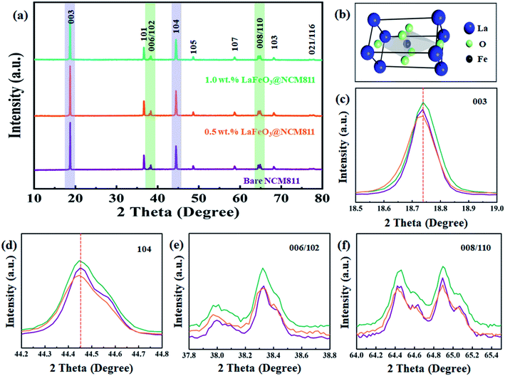
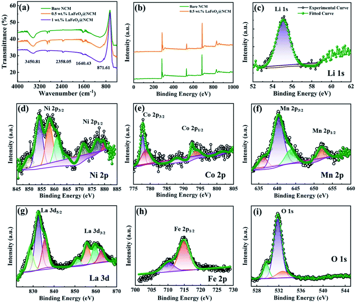
Fig. 1 shows the XRD patterns of bare, 0.5, and 1.0 wt% of LaFeO3-coated NCM811 electrode materials. It can be observed that the peaks of all of the samples are matched to a hexagonal α-NaFeO2 layered structure with a space group of R3m. For 0.5, and 1.0 wt% LaFeO3@NCM811 samples, no clear diffraction peaks belong to orthorhombic LaFeO3 with an ABO3-type perovskite structure (JCPDS card no. 88-641) can be detected because of the low coating content. The Li atom occupies the 3a position, the transition metal (Ni, Co, Mn) atoms occupy the 3b position, and the O atom occupies the 6c position. As shown in Fig. 1(c–f), the double splitting of the (006/102) and (008/110) peaks appeared in all of the samples matches with the layer structure and increasing the amount of coating material does not affect the layered structure of NCM811.36–38The FT-IR spectra of the bare and LaFeO3-coated NCM811 electrode materials are shown in Fig. 2(a). The results suggest that there is an appearance of two different peak positions in the coated materials. The band at 870 cm−1 is attributed to the metal oxide stretching vibration. In particular, the appearance of this Fe–O peak confirms the presence of octahedral FeO6 in LaFeO3.39 Symmetric stretching of the carboxyl C![[double bond, length as m-dash]](https://www.rsc.org/images/entities/char_e001.gif) O bond can be observed at 2360 cm−1 due to atmospheric carbon dioxide, which proceeds without atmospheric correction. The electronic valance state and elemental composition of the as-prepared bare and coated electrode materials were characterized by XPS analysis and the results are shown in Fig. 2(b–i). Fig. 2(b) depicts the wide scan or survey scan spectrum of bare and 0.5 wt% LaFeO3@NCM811, which suggests the presence of the elements of Li 1s, Ni 2p, Co 2p, Mn 2p, La 3d, Fe 2p, and O 1s. Fig. 2(c) shows the Li 1s spectrum with deconvolution of the peaks can be detected at 55.2 eV. Fig. 2(d) represents the core level spectrum of Ni 2p and the two peaks at 856.67 and 872.9 eV correspond to Ni 2p, which index the spin orbital splitting of Ni 2p3/2 and Ni 2p1/2, respectively. Fig. 2(e) represents the deconvoluted spectrum of Co 2p and the peak positions at 780.33 and 794.2 eV are assigned to Co 2p3/2 and Co 2p1/2, respectively.40,41 Fig. 2(f) depicts the deconvoluted spectrum of Mn 2p and the peaks at 643.44 and 657 eV confirm the splitting of Mn 2p3/2 and Mn 2p1/2, respectively. The spectrum of La 3d in Fig. 2(g) shows two strong peaks at 835.72 and 851.05 eV, which match the spin orbital coupling of La 3d5/2 and La 3d3/2, respectively. In Fig. 2(h), the peak at 716.63 eV corresponds to the satellite peak in oxide form. The spectra of La 3d and Fe 2p show the La and Fe atoms in an oxidation valence state of 3.42 Lastly, the spectrum of O 1s in Fig. 2(i) shows peaks at 529.69 and 532.67 eV, which indicates OL and OH, respectively. The OL peak is related to the presence of the La–O and Fe–O bonds in LaFeO3 coating materials and the OH peak represents the hydroxyl group, which is moisture absorbed from the air atmosphere.
O bond can be observed at 2360 cm−1 due to atmospheric carbon dioxide, which proceeds without atmospheric correction. The electronic valance state and elemental composition of the as-prepared bare and coated electrode materials were characterized by XPS analysis and the results are shown in Fig. 2(b–i). Fig. 2(b) depicts the wide scan or survey scan spectrum of bare and 0.5 wt% LaFeO3@NCM811, which suggests the presence of the elements of Li 1s, Ni 2p, Co 2p, Mn 2p, La 3d, Fe 2p, and O 1s. Fig. 2(c) shows the Li 1s spectrum with deconvolution of the peaks can be detected at 55.2 eV. Fig. 2(d) represents the core level spectrum of Ni 2p and the two peaks at 856.67 and 872.9 eV correspond to Ni 2p, which index the spin orbital splitting of Ni 2p3/2 and Ni 2p1/2, respectively. Fig. 2(e) represents the deconvoluted spectrum of Co 2p and the peak positions at 780.33 and 794.2 eV are assigned to Co 2p3/2 and Co 2p1/2, respectively.40,41 Fig. 2(f) depicts the deconvoluted spectrum of Mn 2p and the peaks at 643.44 and 657 eV confirm the splitting of Mn 2p3/2 and Mn 2p1/2, respectively. The spectrum of La 3d in Fig. 2(g) shows two strong peaks at 835.72 and 851.05 eV, which match the spin orbital coupling of La 3d5/2 and La 3d3/2, respectively. In Fig. 2(h), the peak at 716.63 eV corresponds to the satellite peak in oxide form. The spectra of La 3d and Fe 2p show the La and Fe atoms in an oxidation valence state of 3.42 Lastly, the spectrum of O 1s in Fig. 2(i) shows peaks at 529.69 and 532.67 eV, which indicates OL and OH, respectively. The OL peak is related to the presence of the La–O and Fe–O bonds in LaFeO3 coating materials and the OH peak represents the hydroxyl group, which is moisture absorbed from the air atmosphere.
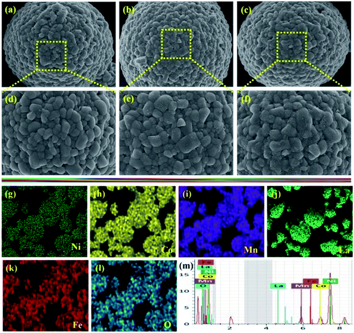
The morphologies of the bare and different ratios of LaFeO3-coated NCM811 electrode materials were characterized by FE-SEM analysis, as shown in Fig. 3(a–f). From the morphological point of view, all of the samples displayed a well-defined spherical particle shape. Fig. 3(a and d) represents the bare NCM811 active material and its magnified image showing a smooth surface with a tiny void space between the secondary particles. Fig. 3(b, e) and (c, f) show the FE-SEM images after surface modification of NCM811 with 0.5 and 1.0 wt% LaFeO3 and there were no differences observed in the structural appearance, suggesting that a small amount of coating materials would not affect the structure of the materials. In addition, it is found that the coated materials effectively cover the surface of the bare NCM811 by hiding the tiny void spaces. When the coating ratio increases, the surface of the core material became rougher, implying that the LaFeO3 was coated successfully on the bare NCM811 surface. Furthermore, EDS mapping shows that all elements are uniformly distributed on the surface of 0.5 wt% LaFeO3@NCM811 cathode material, as shown in Fig. 3(g–l), which is well supported by the EDS elemental spectrum of Fig. 3(m).
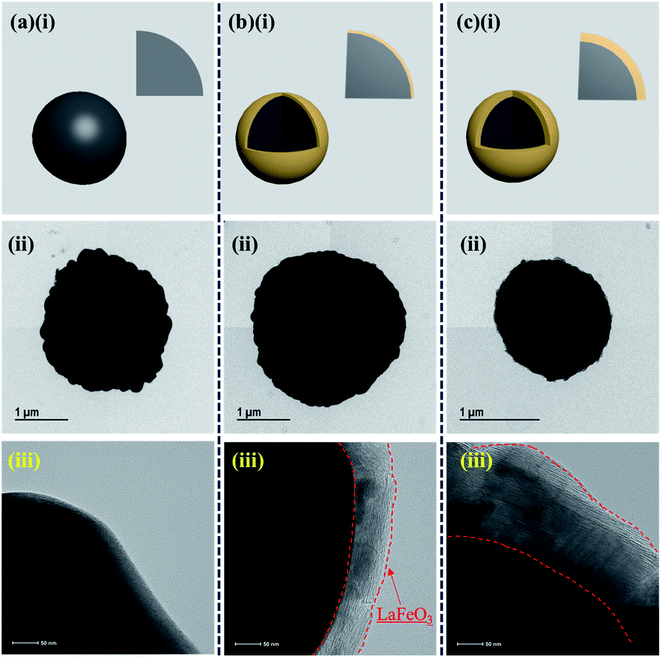
FE-TEM analysis was utilized to explore the internal microstructure of the as-prepared electroactive materials. The FE-TEM images of the bare and different weight percentages of LaFeO3@NCM811 are shown in Fig. 4(a–c). Fig. 4(a–c)(i) shows schematic illustrations of the bare and different weight percentage coated electrode materials. From the FE-TEM analysis, there is an existence of LaFeO3 over the NCM811 electroactive materials for the different ratios. Also, with increasing coating ratio, the thickness of the coating material increased, as evidenced in the high magnification FE-TEM images of Fig. 4(b)(iii) and (c)(iii).
3.2. Electrochemical performance
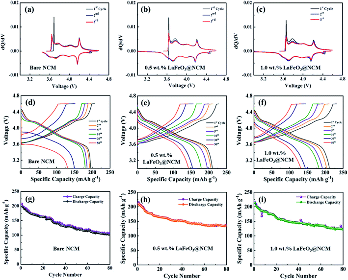
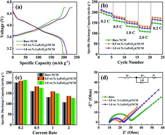
The electrochemical performances of the bare, 0.5, and 1.0 wt% LaFeO3-coated NCM811 were evaluated based on the differential capacity curve (dQ/dV) in the voltage range of 3.0 to 4.6 V. Fig. 5(a–c) represents the differential capacity analysis of the bare, 0.5, and 1.0 wt% LaFeO3@NCM811 for the 1st, 2nd, and 3rd cycle, respectively. From the results, it can be clearly observed that all electrode materials have three oxidation peaks at 3.76 V, 4.02 V, and 4.22 V with corresponding reduction peaks at 3.72 V, 3.98 V, and 4.16 V, which are similar to previously reported values. However, the potential difference of the 0.5 and 1.0 wt% LaFeO3@NCM811 is apparently smaller than that of the bare sample. The 0.5 wt% LaFeO3@NCM811 maintained the redox peak better than the bare electrode, which validates that 0.5 wt% LaFeO3@NCM811 is very favourable for tumbling the kinetic barrier of the electrochemical redox reaction and consequently, improves the electrochemical reversibility. The potential profiles for the bare, 0.5 and 1.0 wt% LaFeO3@NCM811 electrode materials are shown in Fig. 5(d–f). As shown in the figure, bare NCM811 delivered stable electrochemical performance up to 10 cycles and after that, the capacity started to fade due to high voltage operation. The 0.5 and 1.0 wt% LaFeO3@NCM811 electrode materials delivered relatively stable electrochemical performances compared with the bare after the 10th cycle. Fig. 5(g–i) depicts the cycling performance of the bare NCM811 and different ratios of LaFeO3-coated NCM811 electrode materials. With respect to the cycling performance, the first specific charge and discharge capacities of the 0.5 wt% LaFeO3@NCM811 electrode material were 215.4 and 210.3 mA h g−1, respectively, whereas bare NCM811 delivered charge and discharge capacities of about 207.4 and 198.9 mA h g−1, respectively, at a current rate of 0.2C. After 80 cycles, bare NCM811 and 0.5 wt% LaFeO3@NCM811 electrode materials showed specific charge and discharge capacities of 108.5 and 101.5, and 136.1 and 135.8 mA h g−1 with capacity retentions of about 51.0% and 64.6%, respectively. Thus, the proper amount of LaFeO3 coating material could help lead the enhanced durability of the structure during the high voltage operation. It could also suppress the polarization effect during the cycling process. As a result, 0.5 and 1.0 wt% LaFeO3@NCM811 electrode materials might be electrochemically more stable than the bare NCM811.Fig. 6(a) depicts the initial charge–discharge profiles of the bare and different ratio LaFeO3-coated NCM811 electrode materials at a 0.2C in the voltage range of 3.0 to 4.6 V. From the results, the initial specific charge and discharge capacities of the 0.5 wt% LaFeO3@NCM811 electrode material were about 215.4 and 210.3 mA h g−1, respectively, with a coulombic efficiency of 97.6%. The bare and 1.0 wt% LaFeO3@NCM811 electrode materials showed specific charge and discharge capacities of 207.4 and 198.9 mA h g−1, and 221.4 and 212.0 mA h g−1 with coulombic efficiencies of 95.4% and 95.8%, respectively. By comparison, 0.5 wt% LaFeO3@NCM811 electrode material exhibited improved electrochemical performance due to the effective coating ratio of LaFeO3, which can enhance the electrochemical performance. Additionally, rate capability performance is an important factor to evaluate the structural stability at a high current rate in LIBs. Fig. 6(b) depicts the rate capability performance of the bare and different LaFeO3@NCM811 electrode materials. The fabricated coin cells were step-wisely operated from 0.2 to 2C and returned to 0.2C at room temperature. From the results, the delivered discharge capacities of bare NCM811 were 200.8, 161.8, 134.5, and 110.2 mA h g−1 at current rates of 0.2, 0.5, 1.0, and 2.0C, respectively. In comparison, the 0.5 wt% LaFeO3-coated NCM811 electrode material delivered discharge capacities of 208.9, 183.2, 159.5, and 143.2 mA h g−1 at current rates of 0.2, 0.5, 1.0, and 2.0C, respectively. However, the 1.0 wt% LaFeO3-coated NCM811 electrode material delivered discharge capacities of 212.8, 175.5, 149.5, and 126.7 mA h g−1 at current rates of 0.2, 0.5, 1.0, and 2.0C, respectively. From these results, the 0.5 wt% LaFeO3@NCM811 electrode material delivered improved rate capability when compared to the bare and 1.0 wt% LaFeO3@NCM811 electrode materials, producing a higher specific capacity with less electrode polarization even at higher current rates. Fig. 6(c) shows specific discharge capacity behaviors of the bare, 0.5, and 1.0 wt% of LaFeO3@NCM811 cathode electrode materials at different current densities from 0.2 to 2.0C. The 0.5 wt% withstood the highest specific discharge capacity of 143.2 mA h g−1 even at a current rate of 2.0C.
To further investigate the electrochemical performance of the as-prepared bare NCM811 and different ratios of LaFeO3-coated NCM811 electrode materials, the EIS study has been elaborately performed. Fig. 6(d) represents the spectra of bare NCM811 and different ratios of LaFeO3-coated NCM811 electrode materials in a fully charged state of 4.6 V. The inset in Fig. 6(d) represents the equivalent circuit of the EIS which consists of solution resistance (Rs), charge transfer resistance (Rct), Warburg impedance (Zw), and constant phase element (CPE). All of the spectra show a semicircle in the higher frequency region, which belongs to the charge transfer region and the slope in the medium frequency region belongs to the Warburg impedance.43 The Rct values for the bare, 0.5, and 1.0 wt% LaFeO3@NCM811 samples are 20, 10, and 13 Ω, respectively. From Fig. 6(d), the diameter of the semicircle for the 0.5 wt% LaFeO3@NCM811 electrode was smaller than those of the bare and 1.0 wt% samples, which demonstrates good contact between the electrode and the electrolyte, elucidating faster kinetics and increased ion tolerability. Further, this smaller Rct value of the 0.5 wt% LaFeO3@NCM811 electrode could deliver better electrochemical performances among the attempted electrode materials.
4. Conclusion
We have adopted a simple wet chemical synthesis technique to prepare LaFeO3-coated NCM811 electrode materials which were used as a high voltage cathode electrode material in LIBs. Different ratios of LaFeO3 were coated over NCM811 and we systematically investigated the effects of surface modification on electrochemical performance at high voltage, 4.6 V. From the structural analysis, all of the prepared samples were indexed to a well-crystalline structure. In addition, the morphological evaluation revealed that perovskite LaFeO3 is well coated over the NCM811 and it could alleviate the side reactions between the electrolyte and electrode materials. From the electrochemical investigation, LaFeO3-coated NCM811 electrode materials exhibited excellent electrochemical rate capability and cycling performance compared to the bare NCM811. The 0.5 wt% LaFeO3-coated NCM811 electrode material showed better electrochemical performances due to smaller interfacial resistances between electrode and electrolyte during the high voltage operation. These improved properties of LaFeO3-coated NCM811 cathode electrode materials allow them to be considered as a strong contender for next-generation and eco-friendly rechargeable LIBs.Conflicts of interest
There are no conflicts to declare.Acknowledgements
This research was supported by the Next Generation Engineering Researcher Program of National Research Foundation of Korea (NRF) funded by the Ministry of Science and ICT (No. 2017H1D8A2031138) and also supported by the Korea Institute for Advancement of Technology (KIAT) and the Ministry of Trade, Industry & Energy (MOTIE) of the Republic of Korea (No. P0017363).References
- K. J. Kim, Y. N. Jo, W. J. Lee, T. Subburaj, K. Prasanna and C. W. Lee, Effects of inorganic salts on the morphological, structural, and electrochemical properties of prepared nickel-rich Li [Ni0. 6Co0. 2Mn0. 2] O2, J. Power Sources, 2014, 268, 349–355 CrossRef CAS.
- J. Lu, Z. Chen, Z. Ma, F. Pan, L. A. Curtiss and K. Amine, The role of nanotechnology in the development of battery materials for electric vehicles, Nat. Nanotechnol., 2016, 11(12), 1031 CrossRef CAS PubMed.
- E. Sarasketa-Zabala, I. Gandiaga, E. Martinez-Laserna, L. Rodriguez-Martinez and I. Villarreal, Cycle ageing analysis of a LiFePO4/graphite cell with dynamic model validations: Towards realistic lifetime predictions, J. Power Sources, 2015, 275, 573–587 CrossRef CAS.
- Y. Kim, Encapsulation of LiNi0.5Co0.2Mn0.3O2 with a thin inorganic electrolyte film to reduce gas evolution in the application of lithium ion batteries, Phys. Chem. Chem. Phys., 2013, 15(17), 6400–6405 RSC.
- L. Wang, Z. Schnepp and M. M. Titirici, Rice husk-derived carbon anodes for lithium ion batteries, J. Mater. Chem. A, 2013, 1(17), 5269–5273 RSC.
- S. H. Kang, Y. N. Jo, K. Prasanna, T. H. Kim, S. J. Do, P. Santhoshkumar, I. N. Sivagami and C. W. Lee, Physical and Electrochemical Properties of CuO-Coated Li [Ni0.8Co0.1Mn0.1] O2 Cathodes at Elevated Temperature for Lithium Ion Batteries, J. Nanosci. Nanotechnol., 2017, 17(11), 8093–8099 CrossRef CAS.
- W. Liu, P. Oh, X. Liu, M. J. Lee, W. Cho, S. Chae, Y. Kim and J. Cho, Nickel-rich layered lithium transition-metal oxide for high-energy lithium-ion batteries, Angew. Chem., Int. Ed., 2015, 54(15), 4440–4457 CrossRef CAS PubMed.
- X. Xiong, Z. Wang, X. Yin, H. Guo and X. Li, A modified LiF coating process to enhance the electrochemical performance characteristics of LiNi0.8Co0.1Mn0.1O2 cathode materials, Mater. Lett., 2013, 110, 4–9 CrossRef CAS.
- Y. Xia, J. Zheng, C. Wang and M. Gu, Designing principle for Ni-rich cathode materials with high energy density for practical applications, Nano Energy, 2018, 49, 434–452 CrossRef CAS.
- J. Zhang, H. Zhang and J. Xu, Surface-Coated LiNi0.8Co0.1Mn0.1O2 (NCM811) Cathode Materials by Al2O3, ZrO2 and Li2O-2B2O3 Thin-Layers for Improving the Performance of Lithium Ion Batteries, Frontiers in Materials, 2019, 6, 309 CrossRef.
- S. J. Do, P. Santhoshkumar, S. H. Kang, K. Prasanna, Y. N. Jo, C. W. Lee and A.-D. Li, [Ni0. 78Co0. 1Mn0. 1Al0. 02] O2 for High Performance of Lithium Ion Batteries, Ceram. Int., 2019, 45(6), 6972–6977 CrossRef CAS.
- Y. Su, S. Cui, Z. Zhuo, W. Yang, X. Wang and F. Pan, Enhancing the high-voltage cycling performance of LiNi0.5Mn0.3Co0.2O2 by retarding its interfacial reaction with an electrolyte by atomic-layer-deposited Al2O3, ACS Appl. Mater. Interfaces, 2015, 7(45), 25105–25112 CrossRef CAS PubMed.
- M. Hu, X. Pang and Z. Zhou, Recent progress in high-voltage lithium ion batteries, J. Power Sources, 2013, 237, 229–242 CrossRef CAS.
- Y. K. Sun, D. H. Kim, H. G. Jung, S. T. Myung and K. Amine, High-voltage performance of concentration-gradient Li [Ni0. 67Co0. 15Mn0. 18] O2 cathode material for lithium-ion batteries, Electrochim. Acta, 2010, 55(28), 8621–8627 CrossRef CAS.
- P. Hu, J. Zhao, T. Wang, C. Shang, J. Zhang, B. Qin, Z. Liu, J. Xiong and G. Cui, A composite gel polymer electrolyte with high voltage cyclability for Ni-rich cathode of lithium-ion battery, Electrochem. Commun., 2015, 61, 32–35 CrossRef CAS.
- R. Petibon, J. Xia, L. Ma, M. K. Bauer, K. J. Nelson and J. Dahn, Electrolyte system for high voltage li-ion cells, J. Electrochem. Soc., 2016, 163(13), A2571–A2578 CrossRef CAS.
- W. Li, B. Song and A. Manthiram, High-voltage positive electrode materials for lithium-ion batteries, Chem. Soc. Rev., 2017, 46(10), 3006–3059 RSC.
- M. Nanthagopal, P. Santhoshkumar, N. Shaji, S. Praveen, H. S. Kang, C. Senthil and C. W. Lee, Nitrogen-doped carbon-coated Li [Ni0. 8Co0. 1Mn0. 1] O2 cathode material for enhanced lithium-ion storage, Appl. Surf. Sci., 2019, 492, 871–878 CrossRef CAS.
- J. Mou, Y. Deng, L. He, Q. Zheng, N. Jiang and D. Lin, Critical roles of semi-conductive LaFeO3 coating in enhancing cycling stability and rate capability of 5 V LiNi0.5Mn1.5O4 cathode materials, Electrochim. Acta, 2018, 260, 101–111 CrossRef CAS.
- N. Nitta, F. Wu, J. T. Lee and G. Yushin, Li-ion battery materials: present and future, Mater. Today, 2015, 18(5), 252–264 CrossRef CAS.
- K. Meng, Z. Wang, H. Guo, X. Li and D. Wang, Improving the cycling performance of LiNi0.8Co0.1Mn0.1O2 by surface coating with Li2TiO3, Electrochim. Acta, 2016, 211, 822–831 CrossRef CAS.
- S. Li, X. Fu, J. Zhou, Y. Han, P. Qi, X. Gao, X. Feng and B. Wang, An effective approach to improve the electrochemical performance of LiNi0.6Co0.2Mn0.2O2 cathode by an MOF-derived coating, J. Mater. Chem. A, 2016, 4(16), 5823–5827 RSC.
- W. Cho, S. M. Kim, J. H. Song, T. Yim, S. G. Woo, K. W. Lee, J. S. Kim and Y. J. Kim, Improved electrochemical and thermal properties of nickel rich LiNi0.6Co0.2Mn0.2O2 cathode materials by SiO2 coating, J. Power Sources, 2015, 282, 45–50 CrossRef CAS.
- J. Z. Kong, C. Ren, G. A. Tai, X. Zhang, A. D. Li, D. Wu, H. Li and F. Zhou, Ultrathin ZnO coating for improved electrochemical performance of LiNi0.5Co0.2Mn0.3O2 cathode material, J. Power Sources, 2014, 266, 433–439 CrossRef CAS.
- D. Wang, X. Li, Z. Wang, H. Guo, Y. Xu, Y. Fan and J. Ru, Role of zirconium dopant on the structure and high voltage electrochemical performances of LiNi0.5Co0.2Mn0.3O2 cathode materials for lithium ion batteries, Electrochim. Acta, 2016, 188, 48–56 CrossRef CAS.
- C. Li, H. Zhang, L. Fu, H. Liu, Y. Wu, E. Rahm, R. Holze and H. Wu, Cathode materials modified by surface coating for lithium ion batteries, Electrochim. Acta, 2006, 51(19), 3872–3883 CrossRef CAS.
- L. Fu, H. Liu, C. Li, Y. P. Wu, E. Rahm, R. Holze and H. Wu, Surface modifications of electrode materials for lithium ion batteries, Solid State Sci., 2006, 8(2), 113–128 CrossRef CAS.
- N. N. Toàn, S. Saukko and V. Lantto, Gas sensing with semiconducting perovskite oxide LaFeO3, Phys. B, 2003, 327(2–4), 279–282 CrossRef.
- U. Russo, L. Nodari, M. Faticanti, V. Kuncser and G. Filoti, Local interactions and electronic phenomena in substituted LaFeO3 perovskites, Solid State Ionics, 2005, 176(1–2), 97–102 CrossRef CAS.
- S. Khetre, H. Jadhav, P. Jagadale, S. Kulal and S. Bamane, Studies on electrical and dielectric properties of LaFeO3, Adv. Appl. Sci. Res., 2011, 2(4), 503–511 CAS.
- Y. Wang, X. Yang, L. Lu and X. Wang, Experimental study on preparation of LaMO3 (M= Fe, Co, Ni) nanocrystals and their catalytic activity, Thermochim. Acta, 2006, 443(2), 225–230 CrossRef CAS.
- Q. Ming, M. Nersesyan, A. Wagner, J. Ritchie, J. Richardson, D. Luss, A. Jacobson and Y. Yang, Combustion synthesis and characterization of Sr and Ga doped LaFeO3, Solid State Ionics, 1999, 122(1–4), 113–121 CrossRef CAS.
- T. Vijayaraghavan, R. Sivasubramanian, S. Hussain and A. Ashok, A Facile Synthesis of LaFeO3-Based Perovskites and Their Application towards Sensing of Neurotransmitters, ChemistrySelect, 2017, 2(20), 5570–5577 CrossRef CAS.
- M. Humayun, F. Raziq, A. Khan and F. Ali, Controllable Synthesis of Pure-Phase LaFeO3 with Porous Structure and their Catalytic Performance for Pollutants Degradation, SF J. Nanochem. Nanotechnol., 2018, 1(1001), 1–5 Search PubMed.
- M. Marezio and P. Dernier, The bond lengths in LaFeO3, Mater. Res. Bull., 1971, 6(1), 23–29 CrossRef CAS.
- J. Y. Liao and A. Manthiram, Surface-modified concentration-gradient Ni-rich layered oxide cathodes for high-energy lithium-ion batteries, J. Power Sources, 2015, 282, 429–436 CrossRef CAS.
- C. Senthil, K. Vediappan, M. Nanthagopal, H. S. Kang, P. Santhoshkumar, R. Gnanamuthu and C. W. Lee, Thermochemical conversion of eggshell as biological waste and its application as a functional material for lithium-ion batteries, Chem. Eng. J., 2019, 372, 765–773 CrossRef CAS.
- C. Ghanty, B. Markovsky, E. M. Erickson, M. Talianker, O. Haik, Y. Tal-Yossef, A. Mor, D. Aurbach, J. Lampert and A. Volkov, Li+-Ion Extraction/Insertion of Ni-Rich Li1+ x (NiyCozMnz) wO2 (0.005< x< 0.03; y: z= 8: 1, w≈ 1) Electrodes: In Situ XRD and Raman Spectroscopy Study, ChemElectroChem, 2015, 2(10), 1479–1486 CrossRef CAS.
- P. V. Gosavi and R. B. Biniwale, Pure phase LaFeO3 perovskite with improved surface area synthesized using different routes and its characterization, Mater. Chem. Phys., 2010, 119(1–2), 324–329 CrossRef CAS.
- W. Luo and B. Zheng, Improved electrochemical performance of LiNi0.5Co0.2Mn0.3O2 cathode material by double-layer coating with graphene oxide and V2O5 for lithium-ion batteries, Appl. Surf. Sci., 2017, 404, 310–317 CrossRef CAS.
- P. Santhoshkumar, K. Prasanna, Y. N. Jo, I. N. Sivagami, S. H. Kang and C. W. Lee, Hierarchically structured mesoporous bimetallic oxides as a potential anode material for rechargeable lithium batteries, J. Alloys Compd., 2019, 771, 555–564 CrossRef CAS.
- L. Xi, L. Xiaoxun, X. Baokun and Z. Muyu, XPS study of adsorbed oxygen of nanocrystalline LaFeO3 materials, J. Alloys Compd., 1992, 186(2), 315–319 CrossRef.
- P. Santhoshkumar, K. Prasanna, Y. N. Jo, I. N. Sivagami, S. H. Kang and C. W. Lee, A facile and highly efficient short-time homogenization hydrothermal approach for the smart production of high-quality α-Fe 2 O 3 for rechargeable lithium batteries, J. Mater. Chem. A, 2017, 5(32), 16712–16721 RSC.
| This journal is © The Royal Society of Chemistry 2021 |

