
 Open Access Article
 This Open Access Article is licensed under a Creative Commons Attribution-Non Commercial 3.0 Unported Licence
A diamino-functionalized silsesquioxane pillared graphene oxide for CO2 capture†
Eleni Thomou ab,
Viktoria Sakavitsia,
Giasemi K. Angelic,
Konstantinos Spyroua,
Konstantinos G. Froudasc,
Evmorfia K. Diamantia,
George E. Romanosd,
Georgios N. Karanikolosef,
Pantelis N. Trikalitisc,
Dimitrios Gournis*a and
Petra Rudolf*b
ab,
Viktoria Sakavitsia,
Giasemi K. Angelic,
Konstantinos Spyroua,
Konstantinos G. Froudasc,
Evmorfia K. Diamantia,
George E. Romanosd,
Georgios N. Karanikolosef,
Pantelis N. Trikalitisc,
Dimitrios Gournis*a and
Petra Rudolf*b
aDepartment of Materials Science and Engineering, University of Ioannina, Ioannina 45110, Greece. E-mail: dgourni@uoi.gr
bZernike Institute for Advanced Materials, University of Groningen, Nijenborgh 4, 9747 AG, Groningen, The Netherlands. E-mail: p.rudolf@rug.nl
cDepartment of Chemistry, University of Crete, Heraklion 71003, Greece
dInstitute of Nanoscience and Nanotechnology, N.C.S.R. Demokritos, Ag. Paraskevi Attikis, Greece
eDepartment of Chemical Engineering, Khalifa University, Abu Dhabi, P.O. Box 127788, United Arab Emirates
fResearch and Innovation Center on CO2 and H2 (RICH), Khalifa University, Abu Dhabi, P.O. Box 127788, United Arab Emirates
First published on 13th April 2021
Abstract
In the race for viable solutions that could slow down carbon emissions and help in meeting the climate change targets a lot of effort is being made towards the development of suitable CO2 adsorbents with high surface area, tunable pore size and surface functionalities that could enhance selective adsorption. Here, we explored the use of silsesquioxane pillared graphene oxide for CO2 capture; we modified silsesquioxane loading and processing parameters in order to obtain pillared structures with nanopores of the tailored size and surface properties to maximize the CO2 sorption capacity. Powder X-ray diffraction, XPS and FTIR spectroscopies, thermal analysis (DTA/TGA), surface area measurements and CO2 adsorption measurements were employed to characterize the materials and evaluate their performance. Through this optimisation process, materials with good CO2 storage capacities of up to 1.7/1.5 mmol g−1 at 273 K/298 K in atmospheric pressure, were achieved.
1. Introduction
The level of atmospheric carbon dioxide (CO2) emissions, one of the main contributors to global warming, has been increasing dramatically year after year, and despite the attempts towards the moderation and decrease of greenhouse gas production the situation seems irreversible. CO2 is mainly generated from fossil fuel combustion and since there will be no substitute main energy source in the immediate future, the most promising plan of action is Carbon Capture, Utilization and Storage (CCUS).1The capture process of CCUS is focused mainly on industries with high CO2 emissions, such as power plants, refineries and oil production, while Enhanced Oil Recovery (EOR), although not of universal application, offers a unique financial incentive for capturing carbon: using waste CO2 as a source material for producing hydrocarbons and at the same time preventing its harmful release into the atmosphere. In EOR CO2 is injected in almost depleted oil fields in order to force out residual oil and natural gas. The problematic amine-based and ammonia solutions that have been broadly used until now for CO2 capture, need to be replaced by sorbents that are low-cost, easy to scale up and that can be regenerated and reused at low energy cost.2,3 It is well-known that carbon materials such as amorphous carbon, nanotubes, fibers and graphite can be used as sorbents/sieves,4–9 catalytic substrates,10 membranes,11 etc. due to their low mass in combination with chemical inertness, thermal stability and mechanical properties.
Theoretically, defect-free isolated graphene sheets have a very high surface area (∼2630 m2 g−1),12 in addition to being easily (chemically) modified and exhibiting superior mechanical and thermal stability. Graphene is also chemically inert and thus represents an ideal system for sorption and catalysis applications. If the full scientific and technological potential of graphene is to be achieved, lightweight, open 3D structures with high surface area, tuneable pore size and aromatic functionalities must be synthesized. However, the direct use of the unique surface properties of isolated graphene sheets is hampered by the underlying physical–chemical constraints, since due to their aromatic π-systems these structures are extremely prone to aggregation. It is thus clear that the only way to develop nanostructured materials based on graphene or its derivatives as building blocks, is to devise means to maintain the sheets detached. This can be implemented by taking advantage of the concept of intercalation chemistry and the so-called pillaring method, which involves the insertion of suitable and robust organic and/or inorganic species as pillars between the layers. These methods have been successfully applied in other layered structures such as clays13 and layered double hydroxides.14 Pillaring of graphene sheets can provide the necessary structural stability and keep the single carbon layers at a controlled distance, so that a maximum active surface area is easily accessible to small molecules. In such a way, new micro- and meso-porous materials with larger pore sizes than traditional porous materials such as zeolites can be designed. In 2008, using a multiscale theoretical approach Dimitrakakis et al.15 proposed a 3-D nanostructure consisting of parallel graphene layers, connected by carbon nanotube (CNT) pillars. This system, consisting mainly of sp2 hybridised carbon, shows superior structural stability, tuneable porosity and improved storage properties. CNT pillared graphene combines high surface area, narrow and tuneable pore size distributions with available aromatic functionalities arising from both the graphene layers and the CNTs. It is exactly this combination, which makes this class of materials most suitable candidates for the “Holy Grail” storage adsorbent for important gases such as H2.16 Various organic and/or inorganic pillars between graphene layers can impart enhanced and/or diverse properties for gas separation or catalysis, while further “functionalization” can be carried out by the well-established carbon chemistry. Furthermore, by properly choosing the pillaring species, 3D porous structures can be conceived, which are superior to metal organic frameworks (MOFs)17 in terms of stability at higher pressure and durability in normal environmental conditions.
A particularly promising approach is the intercalation of cubic silsesquioxanes as pillaring species in chemically oxidized graphene (graphene oxide, GO). Cubic siloxanes (silsesquioxanes) are synthesized from the hydrolytic condensation of the corresponding trifunctional organosilicon monomers, and offer the opportunity to realize materials with extremely well-defined dimensions and behaviour.18,19 Cubic siloxanes of the type X8Si8O12, where X can be –(CH3)3NH2, or –(CH3)3NH(CH2)2NH2, have been successfully employed as precursor reagents for pillaring inorganic layered solids such as clays20–24 or metal(IV)–H–phosphates.25
In this work we focus on the synthesis and characterization of novel pillared materials where amino-functionalized cubic silsesquioxanes were intercalated among GO layers at different loadings. Silsesquioxanes assure the robustness of the 3-D network of adjacent graphene sheets, while the unreacted amine groups in the open space between the GO sheets warrant strong CO2 adsorption.
2. Materials and methods
2.1 Materials
Graphite (purum, powder <0.1 mm) and N-[3-(trimethoxysilyl)propyl]-ethylenediamine (EDAPTEOS, 97%) were purchased from Sigma Aldrich, whereas potassium chlorate (KClO3, 99+%) was purchased from Alfa Aesar, sulphuric acid (H2SO4, 96%) and ethanol (absolute for analysis) from Merck, and nitric acid (HNO3, 65%) from Penta Chemicals Unlimited, and sodium hydroxide carbonate (NaHCO3, >99.7%) from Riedel-de Haën. All reagents were of analytical grade and used without further purification. The water used in the experiments was distilled and deionized.2.2 Materials synthesis
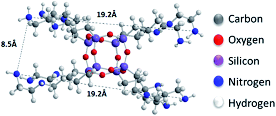 | ||
| Fig. 1 The cage-like structure of the siloxane. | ||
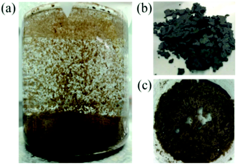 | ||
| Fig. 2 Photographs presenting the flocculation phenomenon (a), and silsesquioxane-pillared GO after air drying (b) and freeze drying (c). | ||
2.3 Characterization techniques
![[thin space (1/6-em)]](https://www.rsc.org/images/entities/char_2009.gif) 999%) was used for the adsorption measurements. Prior to the measurement, each sample was transferred to a 9 mm quartz cell and activated under dynamic vacuum at 100 °C for 20 h (until the output rate was less than 2 mTorr min−1) to remove all volatile species. After activation, the sample was weighed to obtain the precise mass of the solids and the cell was transferred to the analysis port of the gas sorption instrument.
999%) was used for the adsorption measurements. Prior to the measurement, each sample was transferred to a 9 mm quartz cell and activated under dynamic vacuum at 100 °C for 20 h (until the output rate was less than 2 mTorr min−1) to remove all volatile species. After activation, the sample was weighed to obtain the precise mass of the solids and the cell was transferred to the analysis port of the gas sorption instrument.3. Results
Oxidizing graphite powder following the modified Staudenmaier's method,26 produces exfoliated hydrophilic single-layer flakes of graphene oxide (GO), which are perfectly dispersed in water. As detailed above, the pillaring solution was derived from controlled hydrolysis of N-[3-(trimethoxysilyl)propyl]-ethylenediamine (EDAPTEOS) and hydrolytic condensation of the silanes takes place smoothly in an ethanol–H2O solution, resulting in the creation of an octameric cubic structure.23,25 The immediate flocculation observed when the ethanolic solution containing the pillaring agent was added to the GO suspension, hints to the insertion of cubic siloxanes between the GO layers through covalent bonding via the amide functionality of the organosilane molecules. Interaction of the primary aliphatic amines of the EDAPTEOS end groups with GO is expected to take place mainly via nucleophilic substitution reactions on the epoxy groups of GO.27,32The XRD patterns of the pristine graphite, GO and the PILGD samples are shown in Fig. 3. Note that the sharp peak at 21.4° visible in most of the samples, originates from the silicon oxide used as a substrate during the measurements. The pattern of pure graphite exhibits a peak at 26.6° corresponding to the basal spacing d002 = 3.34 Å, while for graphene oxide a 001 reflection32,33 appears at 11.9°, consistent with a basal spacing of d001 = 7.4 Å. Treatment of GO with the siloxane cubes leads to a shift of the peak to lower angles, which confirms an expansion of the interlayer space by the organofunctionalized silicon oxide cubes inserted as bonded pillars between GO sheets. In the case of the air-dried samples, two peaks are distinguished in the XRD patterns, one in the range of 6.3–7.7° and a second one at 9.6°. The existence of these two peaks is due to the different orientations of the cubes, facilitated by the flexibility of the aliphatic chains.34 Applying the Bragg formula (nλ = 2dsinθ), and bearing in mind that the thickness of a graphene oxide layer is 6.1 Å,35 the interlayer distances giving rise to the two peaks are calculated to amount to 11.4–14 Å and 9.2 Å, respectively. Taking into account the intercalant's size as marked in Fig. 1, one concludes that it has adopted a very slightly inclined orientation between the GO sheets. There is also a very broad feature centred around the peak position of pure GO, which indicates that not all layers are pillared and very small coherently diffraction domains of unfilled GO persist in between the pillared structure. On the other hand, in the case of the freeze-dried samples the peak positions cannot readily be discerned because the diffraction pattern shows very broad features, pointing to small coherently diffracting domains.
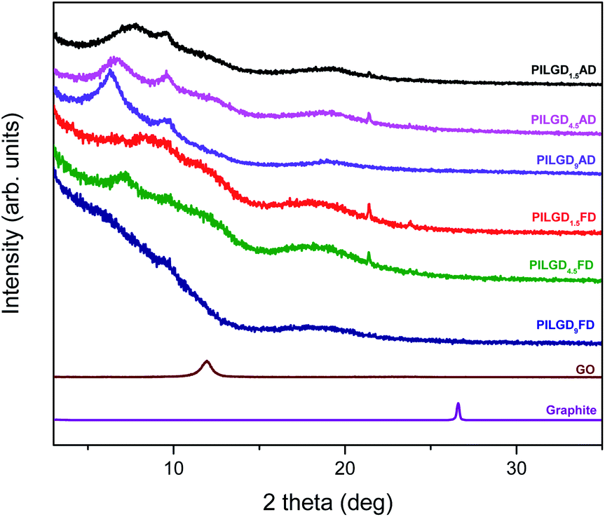 | ||
| Fig. 3 XRD patterns of pristine graphite, graphene oxide, and silsesquioxane-pillared graphene oxide prepared with different loadings and either air-dried or freeze-dried. | ||
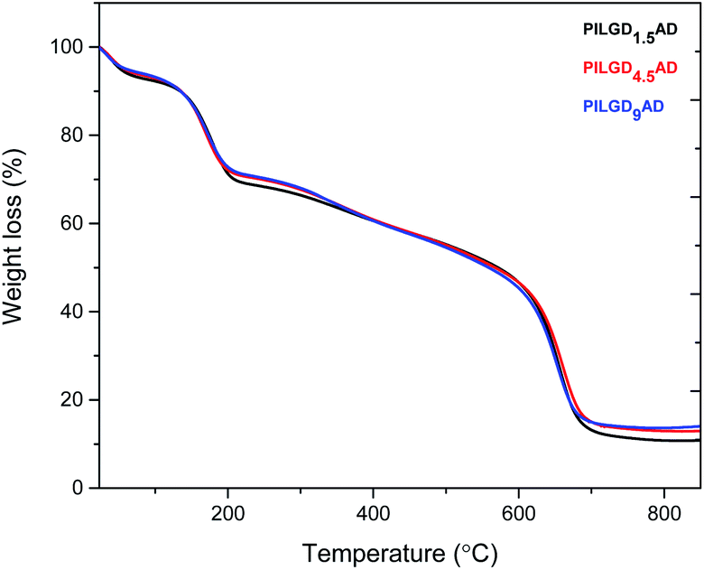
TGA was performed on the air-dried silsesquioxane-pillared structures in order to define the relative amount of silicon oxide for each loading; the results are presented in Fig. 4. Heating up to 250 °C an initial mass loss of ∼24% is noticed, which is attributed to the removal of the adsorbed water and of the oxygen containing groups of the GO.32 Increasing the temperature to 350 °C, a second mass loss of ∼12% is recorded, which can be assigned to the removal of the organic groups bonded to the siloxane cubes, and successively a third weight loss of approximately 45% indicates combustion of the graphene layers. From the remaining weight after heating to 850 °C, we calculated that the inorganic silicon oxide cubes correspond approximately to 10.842, 13.065 and 14.169% of the total mass of the pillared material obtained with 1.5, 4.5 and 9 mmol loading respectively.
 | ||
| Fig. 4 TGA curves of the three air-dried silsesquioxane-pillared graphene oxide structures. | ||
Note that the silicon oxide cubes' content does not scale with the loading because in the last step of the synthesis the samples were washed two times to remove the excess amount of cubes as well as the loosely bonded ones.
An additional characterisation tool, which can confirm the successful incorporation of the silsesquioxane cubes between GO sheets, is FTIR spectroscopy. As shown in Fig. 5, while pure graphite is an IR inactive solid, graphene oxide exhibits all the IR features expected after oxidation, namely at 3411 cm−1 the hydroxyl stretching vibrations of the C–OH groups, at 1630 cm−1 the C![[double bond, length as m-dash]](https://www.rsc.org/images/entities/char_e001.gif) O stretching vibrations of the –COOH groups, at 1069 cm−1 the C–O stretching vibrations, at 1294 cm−1 the asymmetric stretching of C–O–C bridges in epoxy groups, and at 1646 cm−1 the CC stretching vibrations of the aromatic ring.36,37 In the case of the pillared samples, extra peaks appear in the spectrum, which are attributed to the presence of the silsequioxane cubes. In fact, the band at 773 cm−1 is assigned to the stretching vibrations of O–Si–O bonds, and the ones at 445, 596, 1067 and 1197 cm−1 are due to the Si–O–Si bending and stretching vibrations;34,38 together these spectral features confirm the integrity of the silsesquioxane cubes. The band at 692 cm−1 is due to the C–H bending vibrations of the aliphatic chains of the silsequioxane cubes34 and the one at 920 cm−1 stems from Si–O stretching vibrations.39 The spectral fingerprints of C–N at 1315 cm−1, the asymmetric N+–CH3 deformations22 at 1474 cm−1, the –NH3+ deformation23,39 at 1570 cm−1 and the NH2 deformation at 1627 cm−1 together testify to the integrity of the aliphatic chains of the cubes.23 Finally, asymmetric and symmetric stretching vibrations of –CH2– groups observed at 2931 and 2874 cm−1 reveal the presence of organosilane molecules in the solid. Analogous spectra were obtained for all the other pillared samples (data not shown here).
O stretching vibrations of the –COOH groups, at 1069 cm−1 the C–O stretching vibrations, at 1294 cm−1 the asymmetric stretching of C–O–C bridges in epoxy groups, and at 1646 cm−1 the CC stretching vibrations of the aromatic ring.36,37 In the case of the pillared samples, extra peaks appear in the spectrum, which are attributed to the presence of the silsequioxane cubes. In fact, the band at 773 cm−1 is assigned to the stretching vibrations of O–Si–O bonds, and the ones at 445, 596, 1067 and 1197 cm−1 are due to the Si–O–Si bending and stretching vibrations;34,38 together these spectral features confirm the integrity of the silsesquioxane cubes. The band at 692 cm−1 is due to the C–H bending vibrations of the aliphatic chains of the silsequioxane cubes34 and the one at 920 cm−1 stems from Si–O stretching vibrations.39 The spectral fingerprints of C–N at 1315 cm−1, the asymmetric N+–CH3 deformations22 at 1474 cm−1, the –NH3+ deformation23,39 at 1570 cm−1 and the NH2 deformation at 1627 cm−1 together testify to the integrity of the aliphatic chains of the cubes.23 Finally, asymmetric and symmetric stretching vibrations of –CH2– groups observed at 2931 and 2874 cm−1 reveal the presence of organosilane molecules in the solid. Analogous spectra were obtained for all the other pillared samples (data not shown here).
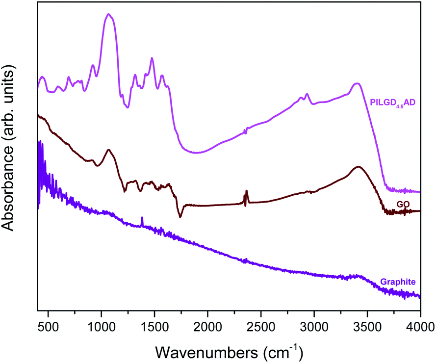 | ||
| Fig. 5 FTIR spectra of graphite, graphene oxide (GO) and air-dried silsesquioxane-pillared graphene oxide structure PILG4.5AD. | ||
X-ray photoelectron spectroscopy was performed on the three air-dried silsesquioxane-pillared structures in order to verify the presence and integrity of the siloxane cubes in the interlayer space of GO and also to evaluate the quality of the graphene-based material in terms of chemical moieties present after intercalation. The detailed spectra of the C 1s and N 1s core level regions are shown in Fig. 6.
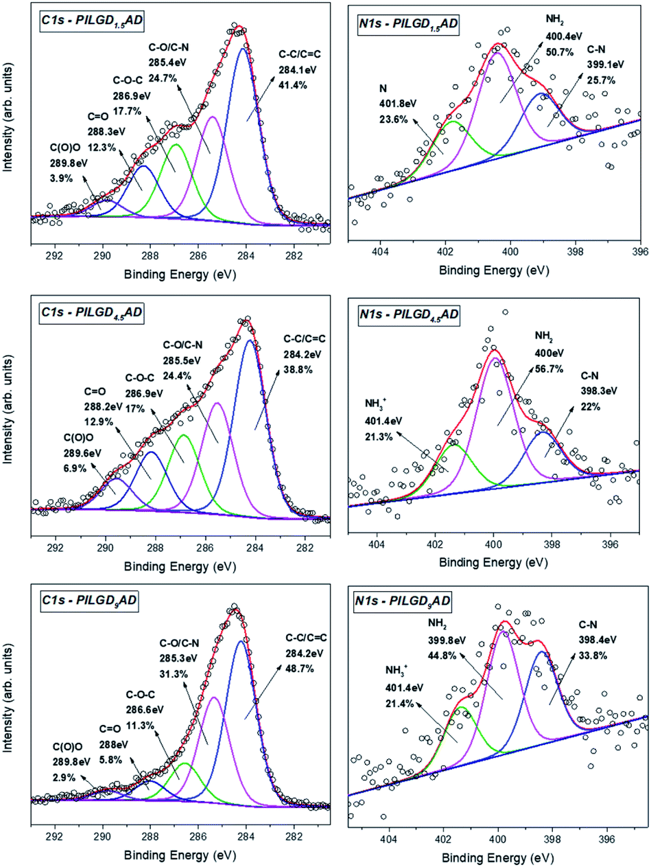 | ||
| Fig. 6 XPS spectra of the C 1s and N 1s core level regions of the silsesquioxane-pillared GO structures obtained with the three different loadings. | ||
Deconvolution of the C 1s spectrum requires five components. The first and most prominent peak at a binding energy (BE) of ∼284.2 eV is attributed to C–C/CC bonds within the graphene oxide layers and contributes with respectively 41.4, 38.8 and 48.7% of the total C 1s spectral intensity for PILGO1,5AD, PILGO4.5AD and PILGO9AD. The second one at a BE of ∼285.4 eV is due to the C–O bonds of the GO lattice as well as from the C–N bonds of the cubes and makes up 24.7, 24.4 and 31.3% of the C 1s spectral intensity for the 3 loadings respectively, while the third component at a BE of ∼286.9 eV originates from the epoxy groups and its lower intensity with respect to pure GO for all 3 loadings (17.7, 17 and 11.3% of the total C 1s spectral intensity) indicates the formation of covalent bonds. Finally, the two components at BEs of ∼288.2 and ∼289.8 eV are attributed respectively to CO bonds (relative intensity 12.3, 12.9 and 5.8% for the three loadings) and to carboxylic groups present in the graphene oxide sheets (relative spectral intensities 3.9, 6.9 and 2.9% for the three loadings).
Through the analysis of the XPS spectra of the N 1s core level region additional insight on the type of interactions can be gained. The nitrogen spectrum requires three components for a good fit: the first one at a BE of ∼398.4 eV is attributed to the covalent bonds formed between the amines and the epoxy groups (relative spectral intensities 25.7, 22 and 33.8% for the three loadings); the second contribution at ∼400 eV is due to amines of the precursor and amounts to respectively 50.7, 56.7 and 44.8% of the total N 1s intensity and the last one at a BE ∼401.4 eV stems from protonated amines (relative spectral intensities 23.6, 21.3 and 21.4% for the three loadings).
The atomic percentages of the elements present in the samples were calculated and are presented in Table 1. The silicon content agrees with the data of the thermal analysis of the samples.
| Element | Atomic percentage % | ||
|---|---|---|---|
| PILGD1.5AD | PILGD4.5AD | PILGD9AD | |
| C | 78.8 | 63.9 | 66.9 |
| O | 10.8 | 21.7 | 21.7 |
| N | 3.5 | 4.1 | 4.1 |
| Si | 6.9 | 10.3 | 7.3 |
The porous structure of the different silsesquioxane-pillared GO samples and of pure GO was studied by recording the N2 adsorption–desorption isotherms at 77 K; the data are presented in the ESI.† The BET specific surface area, deduced from the adsorption data and reported in Table 2 for all samples, is significantly higher for the freeze-dried samples. In fact, for the latter it reaches more than 5 times larger values than those of the air-dried ones synthesized with the same silsesquioxane loading.
| Sample | BET surface area (m2 g−1) | |
|---|---|---|
| AD | FD | |
| GO | 9 | 7 |
| PILGD1.5 | 10 | 50 |
| PILGD4.5 | 9 | 46 |
| PILGD9 | 8 | 42 |
The pillared structures were examined with SEM in order to spot the differences in the structures for the two different ways of drying; representative images of the PILGD4.5AD and PILGD4.5FD samples are shown in Fig. 7. As expected, by simply air drying the samples in ambient conditions, we get compact stacks of graphene oxide layers since with the removal of water the structure shrinks and the layers are only kept apart by the silsesquioxane cubes (left image of Fig. 7). On the other hand, when freeze-drying is employed, the ice crystals sublime, leaving behind pores in the structure.
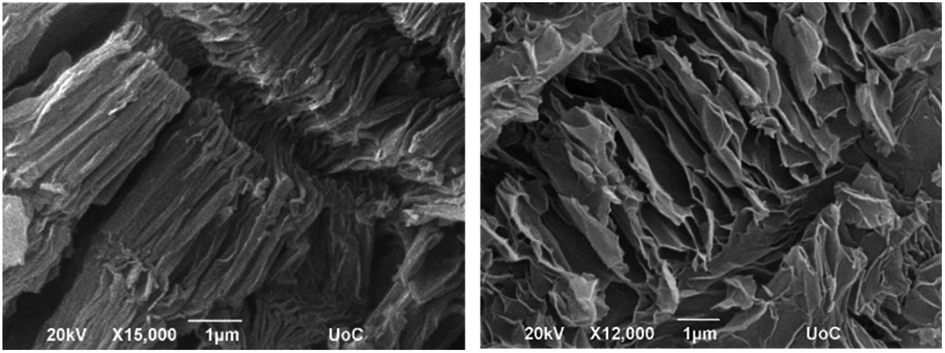 | ||
| Fig. 7 Representative scanning electron microscopy images of the air-dried (PILGO4.5AD, left) and freeze-dried (PILGO4.5FD, right) silsesquioxane-pillared GO structures. | ||
In the SEM image (Fig. 7, right picture) one easily discerns a more foam-like macroscopic structure of the sample, very distinct from the one resulting from air-drying. This explains the increased specific surface area for the freeze-dried samples.
The CO2 adsorption behaviour for all samples was investigated by recording the corresponding adsorption isotherms at 273 K and 298 K, up to 1 bar (see Fig. S2†). For the neat GO samples, although the uptake is relatively poor, the freeze-dried GO is able to capture twice as much CO2 (16.1 cm3 g−1 and 15.3 cm3 g−1, at 273 K and 298 K respectively) as the air-dried one (8 cm3 g−1 and 7.7 cm3 g−1, at 273 K and 298 K respectively). Interestingly, for the pillared freeze-dried samples, the CO2 uptake at 1 bar as a function of surface coverage, does not follow Vegard's law, meaning that it does not monotonically increases with increasing loading. Instead, it shows a maximum value for the intermediate sample PILGD4.5FD, reaching 37 cm3 g−1 and 32.9 cm3 g−1, at 273 K and 298 K, respectively (Fig. 8). The gravimetric uptake is expected to increase with increasing available pore space and decrease with increasing density of the sample. One can anticipate that the insertion of silsesquioxane pillars improves porosity but also makes the material heavier. The lower CO2 uptake of the high loading sample, PILGD9FD (17.9 cm3 g−1 and 17.8 cm3 g−1 at 273 K and 298 K) suggests that this sample is clogged due to an excess of silsesquioxane pillars. In other words, a high amount of pillars reduces the accessible pore space and increases the density of the material, reducing in this way the CO2 gravimetric uptake. The high CO2 uptake of PILGD4.5FD is also supported by the corresponding isosteric heat of adsorption, Qst, calculated using the adsorption isotherms at 273 K and 298 K and applying the Clausius–Clapeyron equation. As shown in Fig. 9, for PILGD4.5FD the Qst at zero coverage is 5.7 kJ mol−1; it slightly increases up to 7.4 kJ mol−1 with increasing loading and drops back to 5.4 kJ mol−1 at high loadings. This behaviour implies the presence of an energetically uniform adsorption environment that favours CO2–CO2 interactions that contributes to high uptake, as has been observed in porous materials, including MOFs.40
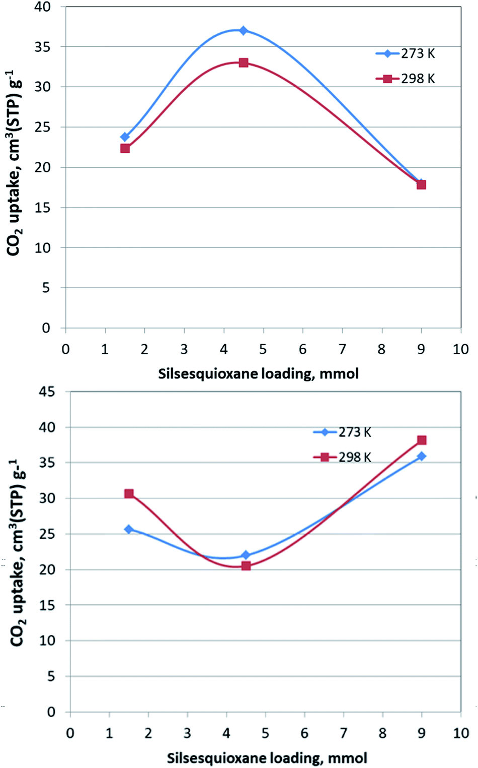 | ||
| Fig. 8 Gravimetric CO2 uptake at 1 bar of PILGD1.5FD, PILGD4.5FD and PILGD9FD as a function of silsesquioxane loading at the indicated temperatures (up) and the equivalent measurements for the air-dried samples (down). | ||
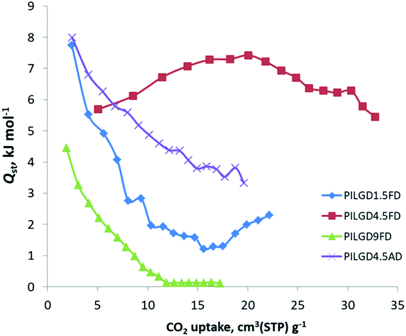 | ||
| Fig. 9 Isosteric heat of adsorption, Qst, as a function of surface coverage, for the indicated solids. | ||
In contrast, the samples with lower and higher silsesquioxane content both show a rapid decrease of the Qst values with increasing CO2 coverage, reaching 2.3 kJ mol−1 and 0.1 kJ mol−1 for PILGD1.5FD and PILGD9FD, respectively. Therefore, the average Qst is significantly lower in both as compared to PILGD4.5FD, consistent with the higher CO2 uptake of the latter.
Interestingly, the air-dried samples show a different CO2 adsorption behaviour, implying a different mechanism of CO2 sorption in these solids (Fig. S2†). An uncommon result is that for PILGD1.5AD and PILGD9AD the CO2 uptake is higher at 298 K than at 273 K, suggesting that CO2 molecules have better access to the porous space in these solids when their kinetic energy is higher. This can be rationalized considering that these samples have a very compact structure as seen in the SEM images, and therefore a higher kinetic energy (higher temperature) is required for the CO2 molecules to be able to penetrate between the layers. The fact that PILGD4.5AD shows marginally higher CO2 uptake at 273 K compared to 298 K, could be associated with a less dense packing of the layers in this case, due to optimum silsesquioxane content. For PILGD4.5AD, the calculated Qst drops also fast as a function of surface coverage, reaching 3.3 kJ mol−1 at high CO2 loading, consistent with the relatively low CO2 uptake 22 cm3 g−1/20.4 kJ mol−1 at 273 K/298 K.
4 Conclusions
Diamino-functionalised silsesquioxane-pillared graphene oxide structures were synthesized in an easily upscalable protocol, by intercalating reactive silylating agents in the interlayer space between the carbon sheets. We showed that by simply opting for freeze-drying, the preferred drying technique in biology as well as in the pharmaceutical and food industries, the porosity can be significantly enhanced as compared to air-drying. The morphology change induced by freeze-drying can lead to an enhanced CO2 adsorption capacity depending on the loading of the pillaring agent. The CO2 storage capacity of the pillared structures that were developed is relatively high despite their low specific surface area – in general considered one of the key characteristics a highly efficient sorbent material. The pillared structure can compete easily with the performance at ambient conditions of other graphene-based materials possessing much higher specific surface areas ranging from 500 to 1000 m2 g−1.41Author contributions
ET: investigation, methodology, data analysis and interpretation, visualization, writing – original draft. VS: investigation, visualization, writing – review & editing. GKA: investigation, data analysis and interpretation, visualization, writing – review & editing. KS: investigation, data analysis and interpretation, supervision, writing – review & editing. KGF: investigation. EKD: investigation. GER: writing – review & editing. GNK: writing – review & editing. PNT: validation, writing – review & editing. DG: conceptualization, supervision, methodology, resources, writing – review & editing. PR: supervision, resources, writing – review & editing. LB: investigation. ODL: investigation. JVD: investigation.Conflicts of interest
There are no conflicts to declare.Acknowledgements
The authors thank Oreste de Luca for the useful discussions, Laura Buis for help with preliminary experiments for this project and Juur van Dijken for the TGA measurements. ET was financially supported by the Hellenic Foundation for Research and Innovation (HFRI) and the General Secretariat for Research and Technology (GSRT), under the HFRI PhD Fellowship grant (GA. No. 1829) and by the Ubbo Emmius programme of the University of Groningen. Financial support by the Abu Dhabi National Oil Company R&D division (project RDProj.018-GP), by the Khalifa University (RC2-2019-007) and by the Advanced Materials Research Program of the Zernike National Research Centre under the Bonus Incentive Scheme (BIS) of the Dutch Ministry for Education, Culture and Science are also greatly appreciated.References
- M. Bui, C. S. Adjiman, A. Bardow, E. J. Anthony, A. Boston, S. Brown, P. S. Fennell, S. Fuss, A. Galindo, L. A. Hackett, J. P. Hallett, H. J. Herzog, G. Jackson, J. Kemper, S. Krevor, G. C. Maitland, M. Matuszewski, I. S. Metcalfe, C. Petit, G. Puxty, J. Reimer, D. M. Reiner, E. S. Rubin, S. A. Scott, N. Shah, B. Smit, J. P. M. Trusler, P. Webley, J. Wilcox and N. Mac Dowell, Energy Environ. Sci., 2018, 11, 1062–1176 RSC.
- A. M. Varghese and G. N. Karanikolos, Int. J. Greenhouse Gas Control, 2020, 96, 103005 CrossRef CAS.
- X. Shi, H. Xiao, H. Azarabadi, J. Song, X. Wu, X. Chen and K. S. Lackner, Angew. Chem., Int. Ed., 2020, 59, 6984–7006 CrossRef CAS PubMed.
- S. Gupta and N.-H. Tai, J. Mater. Chem. A, 2016, 4, 1550–1565 RSC.
- A. M. Varghese, K. S. K. Reddy, S. Singh and G. N. Karanikolos, Chem. Eng. J., 2020, 386, 124022 CrossRef CAS.
- W. Zhang, Y. Bao and A. Bao, J. Environ. Chem. Eng., 2020, 8, 103732 CrossRef CAS.
- Y. Wang, X. Hu, J. Hao, R. Ma, Q. Guo, H. Gao and H. Bai, Ind. Eng. Chem. Res., 2019, 58, 13390–13400 CrossRef CAS.
- J. Shi, N. Yan, H. Cui, Y. Liu and Y. Weng, J. Environ. Chem. Eng., 2017, 5, 4605–4611 CrossRef CAS.
- Y. Liu, M. Xiang and L. Hong, RSC Adv., 2017, 7, 6467–6473 RSC.
- Y. Yang, K. Chiang and N. Burke, Catal. Today, 2011, 178, 197–205 CrossRef CAS.
- C. Li, J. Yang, L. Zhang, S. Li, Y. Yuan, X. Xiao, X. Fan and C. Song, Environ. Chem. Lett., 2020 DOI:10.1007/s10311-020-01112-8.
- A. Peigney, C. Laurent, E. Flahaut, R. R. Bacsa and A. Rousset, Carbon, 2001, 39, 507–514 CrossRef CAS.
- P. Cool and E. F. Vansant, in Synthesis, Springer Berlin Heidelberg, Berlin, Heidelberg, 1998, pp. 265–288, DOI:10.1007/3-540-69615-6_9.
- A. E. Stamate, O. D. Pavel, R. Zavoianu and I. C. Marcu, Catalysts, 2020, 10, 57 CrossRef CAS.
- G. K. Dimitrakakis, E. Tylianakis and G. E. Froudakis, Nano Lett., 2008, 8, 3166–3170 CrossRef CAS PubMed.
- K. Spyrou, D. Gournis and P. Rudolf, ECS J. Solid State Sci. Technol., 2013, 2, M3160–M3169 CrossRef CAS.
- M. Dincă and J. R. Long, Angew. Chem., Int. Ed., 2008, 47, 6766–6779 CrossRef PubMed.
- C. X. Zhang, F. Babonneau, C. Bonhomme, R. M. Laine, C. L. Soles, H. A. Hristov and A. F. Yee, J. Am. Chem. Soc., 1998, 120, 8380–8391 CrossRef CAS.
- R. Tamaki, Y. Tanaka, M. Z. Asuncion, J. W. Choi and R. M. Laine, J. Am. Chem. Soc., 2001, 123, 12416–12417 CrossRef CAS PubMed.
- L. M. Johnson and T. J. Pinnavaia, Langmuir, 1991, 7, 2636–2641 CrossRef CAS.
- G. Fetter, D. Tichit, P. Massiani, R. Dutartre and F. Figueras, Clays Clay Miner., 1994, 42, 161–169 CrossRef CAS.
- D. Petridis, D. Gournis and M. A. Karakassides, Mol. Cryst. Liq. Cryst. Sci. Technol., Sect. A, 1998, 311, 345–350 CrossRef.
- A. Szabo, D. Gournis, M. A. Karakassides and D. Petridis, Chem. Mater., 1998, 10, 639–645 CrossRef CAS.
- G. Balomenou, P. Stathi, A. Enotiadis, D. Gournis and Y. Deligiannakis, J. Colloid Interface Sci., 2008, 325, 74–83 CrossRef CAS PubMed.
- J. Roziere, D. J. Jones and T. Cassagneau, J. Mater. Chem., 1991, 1, 1081–1082 RSC.
- L. Staudenmaier, Ber. Dtsch. Chem. Ges., 1898, 31, 1481–1487 CrossRef CAS.
- R. Y. N. Gengler, A. Veligura, A. Enotiadis, E. K. Diamanti, D. Gournis, C. Jozsa, B. J. van Wees and P. Rudolf, Small, 2010, 6, 35–39 CrossRef CAS PubMed.
- K. Spyrou, M. Calvaresi, E. A. K. Diamanti, T. Tsoufis, D. Gournis, P. Rudolf and F. Zerbetto, Adv. Funct. Mater., 2015, 25, 263–269 CrossRef CAS.
- T. Cassagneau, D. J. Jones and J. Roziere, J. Phys. Chem., 1993, 97, 8678–8680 CrossRef CAS.
- J. K. Moulder, W. F. Stickle, P. E. Sobol and K. D. Bomben, Handbook of X-ray photoelectron spectroscopy, Physical Electronics, Inc., Eden Prairie, MN, 1995 Search PubMed.
- O. Ivashenko, H. Logtenberg, J. Areephong, A. C. Coleman, P. V. Wesenhagen, E. M. Geertsema, N. Heureux, B. L. Feringa, P. Rudolf and W. R. Browne, J. Phys. Chem. C, 2011, 115, 22965–22975 CrossRef CAS.
- A. B. Bourlinos, D. Gournis, D. Petridis, T. Szabo, A. Szeri and I. Dekany, Langmuir, 2003, 19, 6050–6055 CrossRef CAS.
- C. Nethravathi, B. Viswanath, C. Shivakumara, N. Mahadevaiah and M. Rajamathi, Carbon, 2008, 46, 1773–1781 CrossRef CAS.
- G. Potsi, A. K. Ladavos, D. Petrakis, A. P. Douvalis, Y. Sanakis, M. S. Katsiotis, G. Papavassiliou, S. Alhassan, D. Gournis and P. Rudolf, J. Colloid Interface Sci., 2018, 510, 395–406 CrossRef CAS PubMed.
- I. Dekany, R. Kruger-Grasser and A. Weiss, Colloid Polym. Sci., 1998, 276, 570–576 CrossRef CAS.
- V. Ţucureanu, A. Matei and A. M. Avram, Crit. Rev. Anal. Chem., 2016, 46, 502–520 CrossRef PubMed.
- A. Enotiadis, K. Angjeli, N. Baldino, I. Nicotera and D. Gournis, Small, 2012, 8, 3338–3349 CrossRef CAS PubMed.
- R. Peña-Alonso, F. Rubio, J. Rubio and J. L. Oteo, J. Mater. Sci., 2007, 42, 595–603 CrossRef.
- S. Naviroj, S. R. Culler, J. L. Koenig and H. Ishida, J. Colloid Interface Sci., 1984, 97, 308–317 CrossRef CAS.
- I. Spanopoulos, I. Bratsos, C. Tampaxis, D. Vourloumis, E. Klontzas, G. E. Froudakis, G. Charalambopoulou, T. A. Steriotis and P. N. Trikalitis, Chem. Commun., 2016, 52, 10559–10562 RSC.
- R. Ahmed, G. Liu, B. Yousaf, Q. Abbas, H. Ullah and M. U. Ali, J. Cleaner Prod., 2020, 242, 118409 CrossRef CAS.
Footnote |
| † Electronic supplementary information (ESI) available: N2 adsorption–desorption isotherms at 77 K for all silsesquioxane-pillared GO structures prepared with different loadings and both ways of drying; gravimetric CO2 uptake at 1 bar of silsesquioxane-pillared GO structures as a function of silsesquioxane loading, at 273 K and 298 K. See DOI: 10.1039/d1ra00777g |
| This journal is © The Royal Society of Chemistry 2021 |