 Open Access Article
Preparation of Ni-microsphere and Cu-MOF using aspartic acid as coordinating ligand and study of their catalytic properties in Stille and sulfoxidation reactions†
Arash Ghorbani-Choghamarani *a,
Hosna Bastanb,
Zahra Kakakhanib and
Zahra Taheriniab
aDepartment of Organic Chemistry, Faculty of Chemistry, Bu-Ali Sina University, Hamedan 6517838683, Iran. E-mail: arashghch58@yahoo.com; a.ghorbani@basu.ac.ir; Fax: +988138380709; Tel: +988138282807
bDepartment of Chemistry, Ilam University, P.O. Box 69315516, Ilam, Iran
First published on 21st April 2021
Abstract
In this study, the thermal and catalytic behavior of Ni-microsphere and Cu-MOF were investigated with aspartic acid as the coordinating ligand with different morphologies. The Ni-microsphere and Cu-MOF with aspartic acid, as the coordinating ligand, were prepared via a solvothermal method. The morphology and porosity of the obtained Ni microsphere and Cu-MOF were characterized by XRD, FTIR, TGA, DSC, BET and SEM techniques. The catalytic activity of the Ni-microsphere and Cu-MOF was examined in Stille and sulfoxidation reactions. The Ni microsphere and Cu-MOF were easily isolated from the reaction mixtures by simple filtration and then recycled four times without any reduction of catalytic efficiency.
Cross-coupling reaction is one of the most significant methods to create carbon–carbon bonds in organic synthesis. There are many approaches, including, Suzuki, Stille, and Sonogashira cross-coupling reactions, which are well recognized and highly applicable in organic synthesis. Among them, the Stille reaction, which is an increasingly versatile tool for the formation of carbon–carbon bonds, involves the coupling of aryl halides with organotin reagents.1 However, these reactions generally require expensive transition metal catalysts such as Pd.2 Therefore, it is necessary to develop a new economic, green, and efficient methodology to reduce the environmental impact of the reaction. They are also important intermediates in organic chemistry and have been widely used as ligands in catalysis. The direct oxidation of sulfides is an important method in organic chemistry. Besides, they are also valuable synthetic intermediates for the construction of chemically and biologically important molecules, which usually synthesized by transition metal complexes.3 In this regard, different transition metal complexes of mercury(II) oxide/iodine,4 oxo(salen) chromium(V),5 rhenium(V) oxo,6 H5IO6/FeCl3,7 Na2WO4/C6H5PO3H2,8 chlorites and bromites,9 NBS10 etc. have been introduced as catalysts. However, these catalysts have several drawbacks; including, separation problems from the reaction medium, harsh reaction conditions, and generating a lot of waste. In order to solve these drawbacks, of separation and isolation of expensive homogeneous catalysts is the heterogenization of homogeneous catalysts and generation of a new heterogeneous catalytic system. Metal–organic frameworks (MOFs) are a class of porous crystalline materials, which show great advantages, i.e. their enormous structural and chemical diversity in terms of high surface area,11,12 pore volumes,13 high thermal,14 and chemical stabilities,15 various pore dimensions/topologies, and capabilities to be designed and modified after preparation.16 In this sense, it is worth mentioning that these features would result in viewing these solids as suitable heterogeneous catalysts for organic transformations.17–22 MOFs materials are prepared using metal ions (or clusters) and organic ligands in solutions (i.e. solvothermal or hydrothermal synthesis). MOF structures are affected by metal and organic ligands, leading to have more than 20
![[thin space (1/6-em)]](https://www.rsc.org/images/entities/char_2009.gif) 000 different MOFs with the largest pore aperture (98 Å) and lowest density (0.13 g cm−3).23 Generally, surface area and pore properties of MOFs seem quite dependent on their metal and ligand type as well as synthesis conditions and the applied post-synthesis modifications. The largest surface area was measured in Al-MOF (1323.67 m2 g−1)24,25 followed by ZIF-8-MOF (1039.09 m2 g−1),26 while the lowest value was with Zn-MOF (0.86 m2 g−1),27 followed by γ-CD-MOF (1.18 m2 g−1)28 and Fe3O(BDC)3 (7.6 m2 g−1).29 Microspheres are either microcapsule or monolithic particles, with diameters in the range (typically from 1 μm to 1000 μm),29 depending on the encapsulation of active drug moieties. In this regard, there are two types of microspheres: microcapsules, defined, as spherical particles in the size range of about 50 nm to 2 mm and micro matrices.30 Microsphere structures have recently attracted much attention due to their unique properties, such as large surface area,31 which make them suitable for tissue regenerative medicine,32 i.e. as cell culture scaffolds,33 drug-controlled release carriers34 and heterogeneous catalysis.35 Many chemical synthetic methods has been developed for their synthesis, including seed swelling,36 hydrothermal or solvothermal methods,36 polymerization,37 spray drying38 and phase separation.39 Among these methods, the solvothermal synthesis has been used as the most suitable methodology to prepare a variety of nanostructural materials, such as wire, rod,40 fiber,41 mof42 and microsphere.43 In this sense, the synthesis process involves the use of a solvent under unusual conditions of high pressure and high temperature.44 The properties of microspheres are highly dependent on the number of pores, pore diameter and structure of pore.45 The degree of porosity depends on various factors such as temperature, pH, stirring speed, type, and concentration of porogen, polymer, and its concentration.46 There have been numerous studies to investigate the coordination behavior of a ligand with different metals under the same conditions.47–49 Herein, we aim at comparing the catalytic behavior of Ni-microsphere and Cu-MOF with aspartic acid as the coordinating ligand in Stille and sulfoxidation reactions (Scheme 1).
000 different MOFs with the largest pore aperture (98 Å) and lowest density (0.13 g cm−3).23 Generally, surface area and pore properties of MOFs seem quite dependent on their metal and ligand type as well as synthesis conditions and the applied post-synthesis modifications. The largest surface area was measured in Al-MOF (1323.67 m2 g−1)24,25 followed by ZIF-8-MOF (1039.09 m2 g−1),26 while the lowest value was with Zn-MOF (0.86 m2 g−1),27 followed by γ-CD-MOF (1.18 m2 g−1)28 and Fe3O(BDC)3 (7.6 m2 g−1).29 Microspheres are either microcapsule or monolithic particles, with diameters in the range (typically from 1 μm to 1000 μm),29 depending on the encapsulation of active drug moieties. In this regard, there are two types of microspheres: microcapsules, defined, as spherical particles in the size range of about 50 nm to 2 mm and micro matrices.30 Microsphere structures have recently attracted much attention due to their unique properties, such as large surface area,31 which make them suitable for tissue regenerative medicine,32 i.e. as cell culture scaffolds,33 drug-controlled release carriers34 and heterogeneous catalysis.35 Many chemical synthetic methods has been developed for their synthesis, including seed swelling,36 hydrothermal or solvothermal methods,36 polymerization,37 spray drying38 and phase separation.39 Among these methods, the solvothermal synthesis has been used as the most suitable methodology to prepare a variety of nanostructural materials, such as wire, rod,40 fiber,41 mof42 and microsphere.43 In this sense, the synthesis process involves the use of a solvent under unusual conditions of high pressure and high temperature.44 The properties of microspheres are highly dependent on the number of pores, pore diameter and structure of pore.45 The degree of porosity depends on various factors such as temperature, pH, stirring speed, type, and concentration of porogen, polymer, and its concentration.46 There have been numerous studies to investigate the coordination behavior of a ligand with different metals under the same conditions.47–49 Herein, we aim at comparing the catalytic behavior of Ni-microsphere and Cu-MOF with aspartic acid as the coordinating ligand in Stille and sulfoxidation reactions (Scheme 1).
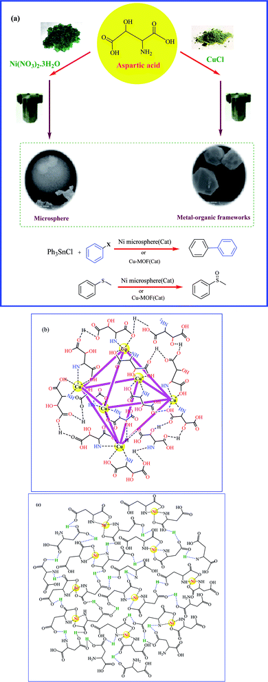 | ||
| Scheme 1 (a) Schematic synthesis of Ni microsphere and Cu-MOF and their application as catalyst (b) topological structure of Cu-MOF (c) topological of Ni microsphere. | ||
Results and discussion
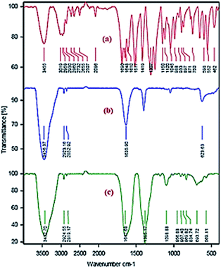
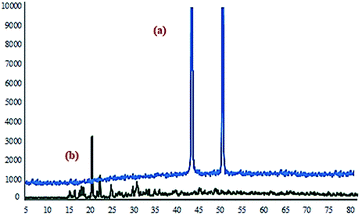
The morphology and porosity of the obtained Ni microsphere and Cu-MOF were characterized using a field emission scanning electron microscopy (FESEM), Fourier transforms infrared spectroscopy (FTIR), the powder X-ray diffraction (PXRD), thermogravimetric analysis (TGA), differential scanning calorimetry (DSC) and nitrogen adsorption–desorption isotherm. In order to get information for the binding mode of the aspartic acid to Cu and Ni in the complexes, the FTIR spectrum of the free aspartic acid compared to the corresponding metal complexes (Fig. 1).X-ray diffraction pattern (XRD) analysis employed to investigate the crystalline structure of the synthesized Ni microspheres. The reflection peaks of Ni microspheres with 2θ of 44.4°, 50.5 shown in Fig. 2a, indexed to (111), and (200) might be assign to the cubic phase of Ni.50 Also, X-ray diffraction pattern (XRD) analysis was carried out to study the crystalline structure of (Cu-MOF), as shown in Fig. 2b. All observed major peaks at 16.5° (422), 17.5° (511), 19.1° (440) and other minor peaks are the characteristics of crystal planes of face-centred cubic, as reported in the previously reported work.51
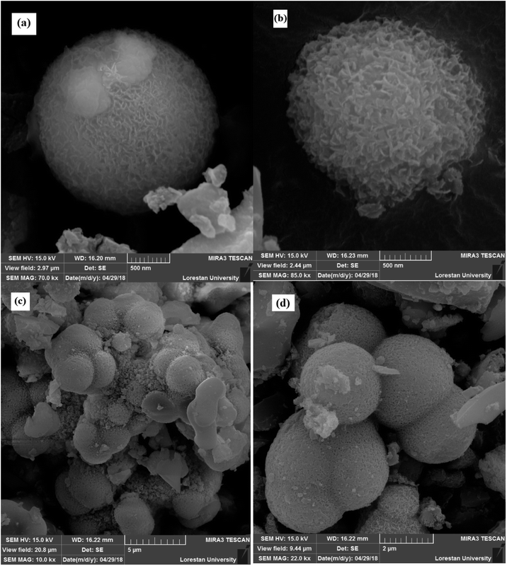
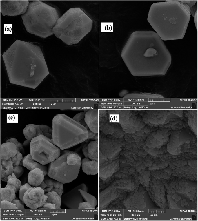
The morphologies of Ni microsphere and Cu-MOF considered by SEM (Fig. 3 and 4) analysis. Fig. 3a and b show the SEM images of microspheres at distant and close view, respectively. From the SEM image of Fig. 3a, it could be found that synthesized microspheres were spherical in shape. Fig. 3b shows the SEM images of hollow flower-like microspheres. It should be noted that the microspheres/microcapsules in nanometer size could be described as miniature-sized particles such as nanospheres/nanocapsules.30 Moreover, Fig. 4 shows that the synthesized MOF has different polyhedron morphologies. Fig. 4a shows the synthesized octahedral and rhombic dodecahedral crystals. Furthermore, the SEM images of the hexagonal are presented in Fig. 4b. The SEM image with in Fig. 4d presents a clear view of the surface morphology of Cu-MOF.
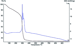
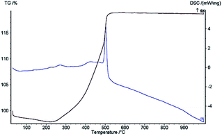
DSC and TG curves under the linear heating rate of 10 °C min−1 with air atmosphere are shown in Fig. 5 and 6, indicating the thermal decomposition behavior of Ni microsphere and Cu-MOF. Regarding the Ni microsphere, the DSC curve shows that one intense exothermic peak process starts at 300 °C and, then, terminates at 350 °C, due to the melting temperature of the Ni microsphere. Fig. 5 shows the TGA of the Ni microsphere, indicating that the 7% weight loss below 200 °C can be related to the removal of water which is physically adsorbed. Furthermore the weight loss of about 12% is observed at 300 °C, which is related to the thermal evaporation of organic ligand molecules, while the next weight loss (45%) between 300–500 °C is due to the microsphere decomposition. The weight of the microsphere did not decrease further at temperatures above 500 °C, indicating that only inorganic matter remained after decomposition. In the thermostability of Cu-MOF, an increase in sample mass was observed due to copper oxide formation in a temperature range of 200 °C to 500 °C (Fig. 5).52 Regarding Cu-MOF, the DSC curve shows that one intense exothermic process starts at 480 °C and, then, terminates at 550 °C, due to copper oxide formation (Fig. 6).
The N2 adsorption–desorption isotherms and BJH pore size distribution plots of the samples were presented in Fig. S1 and S2.† The Brunauer–Emmett–Teller surface area (SBET) Ni microsphere and Cu-MOF are determined to be 5.88 m2 g−1, and 9.23 m2 g−1 respectively based on the N2 adsorption–desorption measurement. The BJH pore size calculations using the adsorption branch of the nitrogen isotherm indicate a micropore peak at about 1.22 nm for Ni microsphere (Fig. S1†), and Cu-MOF (Fig. S2†).
Catalytic study
After the preparation and characterization of Ni microsphere and Cu-MOF, the catalytic activity of these compounds was investigated for the Stille and sulfoxidation reactions. We commenced our study with the reaction of iodobenzene and triphenyltin chloride in the presence of Ni microsphere as a model reaction, and different parameters which are the different bases, solvent, and temperature were optimized (the results are summarized in Table 1).| Entrya | Solvent | Temp. (°C) | Cat (mg) | Base (mmol) | Base | Time (h) | Yieldb (%) |
|---|---|---|---|---|---|---|---|
| a Reaction conditions: iodobenzene (1 mmol), triphenyltin chloride (0.5 mmol), Ni microsphere (mg), base (3 mmol).b Isolated yield.c The control experiment confirmed that the reaction did not occur in the absence of base.d The control experiment confirmed that the reaction did not occur in the absence of Ni microsphere. | |||||||
| 1 | DMSO | 100 | 50 | 3 | K2CO3 | 3![[thin space (1/6-em)]](https://www.rsc.org/images/entities/char_2009.gif) : :![[thin space (1/6-em)]](https://www.rsc.org/images/entities/char_2009.gif) 45 45 |
N.R. |
| 2 | DMSO | 100 | 50 | 3 | KOH | 4 | 90 |
| 3 | DMSO | 100 | 50 | 3 | NOH | 7 | 53 |
| 4 | DMSO | 100 | 50 | 3 | Na2CO3 | 4 | N.R. |
| 5 | DMF | 100 | 50 | 3 | KOH | 4 | 25 |
| 6 | H2O | 100 | 50 | 3 | KOH | 4 | N.R. |
| 7 | PEG | 100 | 50 | 3 | KOH | 4 | N.R. |
| 8 | DMSO | 100 | 40 | 3 | KOH | 4 | 81 |
| 9c | DMSO | 100 | 50 | — | — | 4 | N.R. |
| 10d | DMSO | 100 | — | 3 | KOH | 4 | N.R. |
| 11 | DMSO | 80 | 50 | 3 | KOH | 4 | 60 |
 |
|||||||
First, several solvents were screened (Table 1), and, then, the highest yield was obtained in DMSO (Table 1, entry 2), while the reaction in other solvents such as PEG, DMF, and water was ineffective (Table 1, entries 5–7). We investigated the effect of various bases (e.g., KOH, NaOH, K2CO3, and Na2CO3), and it was revealed that KOH was the most effective base (Table 1, entry 2). In the absence of Ni microsphere and Cu-MOF catalyst, no desired product was formed (Table 1, entry 10). The control experiment confirmed that the reaction did not occur in the absence of the catalyst (Table 1, entry 10) as well as the base (Table 1, entry 9). When the reaction was conducted at 80 °C, the yields were very low (Table 1, entry 11). The ideal temperature for the reaction was found to be 100 °C. Moreover, the optimized conditions for Ni catalysts applied to the synthesis of a variety of biphenyls in the presence of Cu-MOF at 100 °C (Table 2). As shown in Table 2, a large number of biphenyl was synthesized from the reaction of aryl halides (1.0 mmol) with triphenyltin chloride (0.5 mmol) in the presence of Ni microsphere and Cu-MOF. As can be seen from Table 2, a good variety of aryl halides with both electron-withdrawing and electron-releasing groups in ortho, para, or meta positions, reacted effectively with triphenyltin chloride to produce corresponding biphenyls (Table 2).
| Entrya | Ar–X | Product | Time (h) | Yieldb (%) | ||
|---|---|---|---|---|---|---|
| Ni microsphere | Cu-MOF | Ni microsphere | Cu-MOF | |||
| a Reaction conditions: aryl halide (1 mmol), triphenyltin chloride (0.5 mmol), catalyst (50 mg), KOH (3 mmol).b Isolated yield. | ||||||
| 1 |  |
 |
4 | 3.5 | 90 | 94 |
| 2 |  |
 |
10 | 10 | 78 | 83 |
| 3 |  |
 |
24 | 24 | 35 | 39 |
| 4 |  |
 |
24 | 20 | 81 | 85 |
| 5 |  |
 |
24 | 24 | 75 | 77 |
| 6 |  |
 |
4.5 | 3 | 80 | 88 |
| 8 |  |
 |
24 | 24 | 58 | 66 |
| 8 |  |
 |
24 | 24 | 65 | 71 |
| 9 |  |
 |
24 | 18 | 76 | 80 |
| 10 |  |
 |
14 | 13 | 87 | 87 |
| 11 |  |
 |
3 | 3 | 55 | 62 |
The proposed mechanism for the synthesis of biphenyl is shown in Scheme 2. We hypothesize that Cu-MOF reacts with aryl halide, in which Cu was inserted between phenyl ring and halide moiety and, then, the coupling product is obtained through transmetalation and reductive elimination (Scheme 2).
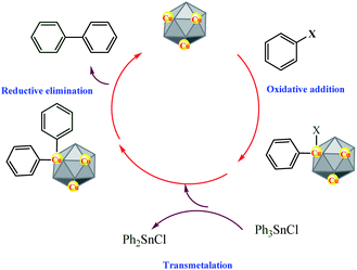 | ||
| Scheme 2 Proposes a mechanism for the synthesis of biphenyl via reaction of triphenyltin chloride with aryl halides catalyzed by Cu-MOF. | ||
The reactivity of Ni microsphere and Cu-MOF was also examined for the sulfoxidation reaction. In order to find the best reaction conditions, methyl phenyl sulfide was selected as a model substrate and its oxidation with hydrogen peroxide was investigated in the presence of Ni microsphere in EtOH, CH3CN, CH2Cl2, and EtOAc as an organic solvent or in solvent-free conditions. The results from these experiments are summarized in Table 3. It was found that when the reaction proceeded in the presence of Ni microsphere in EtOH, CH3CN, CH2Cl2, and EtOAc, the observed yield was very low. Moreover, we investigated the effect of the catalyst the catalyst amount on the yield of the product was considered. It was observed that 25 mg of Ni microsphere was the optimum value for this conversion. It is worth mentioning that a good result was obtained when the reaction was performed at room temperature using Ni microsphere under solvent-free conditions. In order to clarify the special of Ni microsphere for the selective oxidation of sulfides to sulfoxides in a set of experiments the model reaction was carried out in the absence of the catalyst and only trace amounts of the product were observed (Table 3, entry 8). Additionally, the obtained optimized conditions for Ni catalyst were applied to the synthesis of a variety of sulfides in the presence of Cu-MOF (Table 4).
| Entrya | Sulfide | Sulfoxide | Time (min) | Yield (%)b | ||
|---|---|---|---|---|---|---|
| Ni microsphere | Cu-MOF | Ni microsphere | Cu-MOF | |||
| a Reaction condition: sulfide (1 mmol), H2O2 30% (0.4 mL), solvent-free, r.t.b Isolated yield.c The reaction was carried out in aqueous ethanol. | ||||||
| 1 |  |
 |
45 | 35 | 90 | 90 |
| 2 |  |
 |
5 | 5 | 86 | 87 |
| 3c |  |
 |
240 | 210 | 70 | 79 |
| 4 |  |
 |
50 | 38 | 90 | 96 |
| 5 | Dodecyl methyl sulfide | Dodecyl methyl sulfoxide | 120 | 95 | 89 | 89 |
| 6c |  |
 |
180 | 140 | 80 | 86 |
| 7 |  |
 |
30 | 20 | 80 | 81 |
| 8 |  |
 |
45 | 40 | 80 | 87 |
Heterogeneity studies
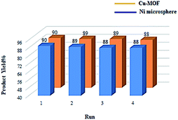
The most important advantage of heterogeneous catalysis is the ease of separation after reaction by simple filtration and also its reusability. The recyclability of Ni microsphere and Cu-MOF was examined for the oxidation of methyl phenyl sulfide under the optimized reaction conditions. Upon completion of the reaction, the catalyst was separated by simple centrifugation, washed with ethyl acetate and acetone, dried in a vacuum and, finally, reused for the subsequent reactions up to 4 times (Fig. 7). The result shows that the catalytic activity of Ni microsphere and Cu-MOF was highly stable and recyclable in each reaction cycle.
To attain further evaluation of the efficiency of the catalytic system, we compared the catalytic activity of Cu-MOF and Ni-MOF for the oxidation of methyl phenyl sulfide with some of the previously reported procedures (Table 5). Comparison of the results shows a better catalytic activity for Cu-MOF and Ni-MOF for the oxidation of methyl phenyl sulfide (Table 5).
Conclusion
In summary, the thermal and the catalytic behaviour of Ni-microsphere and Cu-MOF was studied with aspartic acid, as a coordinating ligand with different morphologies, prepared via the solvothermal method. Afterwards, they were characterized and, then, employed as heterogeneous catalysts for Stille and sulfoxidation reactions. Cu-MOF exhibited high activity in the Stille and sulfoxidation reactions. The major advantages of the mentioned catalytic systems are the use of eco-friendly and cheap materials, easy and simple workup procedure and high chemoselectivity. Moreover, the nanocatalyst can be easily recovered and reused at least four times without any noticeable loss of its activity.Experimental
Synthesis of copper-based metal organic frameworks
In the present study, aspartic acid (1 mmol) was added in 5 mL double-distilled water, then 2 mmol CuCl dissolved dimethylformamide (20 mL) was added. The mixture of metal and ligand is stirred for 10 min, then transferred into the autoclave at 160 °C for 15 h. The solid Cu-MOFs sample was filtered, washed with ethyl acetate. Finally, the precipitate was dried at 60 °C in a vacuum.Synthesis of nickel microsphere
In a typical experiment, aspartic acid (1 mmol) was dissolved in 5 mL double-distilled water, followed by mixing 2 mmol Ni (NO3)2·3H2O in dimethylformamide (20 mL). The obtained mixture was vigorously stirred for 10 min, then transferred into the autoclave at 160 °C for 15 h. Ni microsphere was filtered and washed with ethyl acetate. Finally, the precipitate was dried at 60 °C in a vacuum.General protocol for the synthesis of biaryl
To a mixture of aryl halide (1.0 mmol) and triphenyltin chloride (0.5 mmol) in DMSO (4 mL) Ni microsphere and Cu-MOF (50 mg) and KOH (3 mmol) were added. The reaction mixture was heated to 100 °C and the reaction was monitored by TLC. At the end of the reaction, the mixture cooled and extracted with ethyl acetate. The organic layer was washed successively with brine and water, and dried with Na2SO4. Ethyl acetate filtrated. The filtrate was concentrated under vacuum and the residue was subjected to column chromatography on silica gel using hexane![[thin space (1/6-em)]](https://www.rsc.org/images/entities/char_2009.gif) :
:![[thin space (1/6-em)]](https://www.rsc.org/images/entities/char_2009.gif) ethylacetate (10
ethylacetate (10![[thin space (1/6-em)]](https://www.rsc.org/images/entities/char_2009.gif) :
:![[thin space (1/6-em)]](https://www.rsc.org/images/entities/char_2009.gif) 1) as eluent to afford the pure coupled product.
1) as eluent to afford the pure coupled product.
General protocol for the oxidation of sulfide to sulfoxide
To a mixture of sulfide (1 mmol), H2O2 30% (0.4 mL) at 25 °C under solvent-free conditions Cu-MOF or Ni microsphere as catalyst (25 mg) was added. At the end of the reaction, the mixture was extracted with ethyl acetate (2 × 20 mL). The organic layer was washed successively with brine and water, and dried with Na2SO4. Ethyl acetate filtrated. The filtrate was concentrated under vacuum and the residue was subjected to column chromatography on silica gel using hexane![[thin space (1/6-em)]](https://www.rsc.org/images/entities/char_2009.gif) :
:![[thin space (1/6-em)]](https://www.rsc.org/images/entities/char_2009.gif) ethylacetate (8
ethylacetate (8![[thin space (1/6-em)]](https://www.rsc.org/images/entities/char_2009.gif) :
:![[thin space (1/6-em)]](https://www.rsc.org/images/entities/char_2009.gif) 2) as eluent to afford the pure coupled product.
2) as eluent to afford the pure coupled product.
Selected spectral data
Conflicts of interest
The authors declare no conflict of interest.Acknowledgements
The authors would like to thank the research facilities of Ilam University and Bu-Ali Sina University for the financial support of this research project.References
- C. Cordovilla, C. Bartolomé, J. M. Martínez-Ilarduya and P. Espinet, ACS Catal., 2015, 5, 3040–3053 CrossRef CAS.
- V. Farina, V. Krishnamurthy and W. J. Scott, The Stille Reaction, John Wiley & Sons, Inc., 1998 Search PubMed.
- K. Suwanborirux, K. Charupant, S. Amnuoypol, S. Pummangura, A. Kub and N. Saito, J. Nat. Prod., 2002, 65, 935–937 CrossRef CAS PubMed.
- K. Orito, T. Hatakeyama, M. Takeo and H. Suginome, Synthesis, 1995, 1357–1358 CrossRef CAS.
- R. Sevvel, S. Rajagopal, C. Srinivasan, N. I. Alhaji and A. Chellamani, J. Org. Chem., 2000, 65, 3334–3340 CrossRef CAS.
- J. B. Arterburn and S. L. Nelson, J. Org. Chem., 1995, 61, 2260–2261 CrossRef.
- S. S. Kim, K. Nehru, S. S. Kim, D. W. Kim and H. C. Jung, Synthesis, 2002, 2484–2486 CrossRef CAS.
- K. Sato, M. Hyodo, M. Aoki, X. Q. Zheng and R. Noyori, Tetrahedron, 2001, 57, 2469–2476 CrossRef CAS.
- M. Hirano, H. Kudo and T. Morimoto, Bull. Chem. Soc. Jpn., 1994, 67, 1492–1494 CrossRef CAS.
- K. Surendra, N. S. Krishnaveni, V. P. Kumar, R. Sridhar and K. R. Rao, Tetrahedron Lett., 2005, 46, 4581–4583 CrossRef CAS.
- R. Antwi-Baah and H. Liu, Materials, 2018, 11, 2250 CrossRef PubMed.
- Y. Z. Chen, B. Gu, T. Uchida, J. Liu, X. Liu, B. J. Ye and H. L. Jiang, Nat. Commun., 2019, 10, 1–10 CrossRef PubMed.
- V. Bon, E. Brunner, A. Pöppl and S. Kaskel, Adv. Funct. Mater., 2020, 1907847 CrossRef CAS.
- H. L. Wang, H. Yeh, Y. C. Chen, Y. C. Lai, C. Y. Lin, K. Y. Lu and D. H. Tsai, ACS Appl. Mater. Interfaces, 2018, 10, 9332–9341 CrossRef CAS PubMed.
- A. J. Howarth, Y. Liu, P. Li, Z. Li, T. C. Wang, J. T. Hupp and O. K. Farha, Nat. Rev. Mater., 2016, 1, 1–15 Search PubMed.
- M. V. Parkes, C. L. Staiger, J. J. Perry IV, M. D. Allendorf and J. A. Greathouse, Phys. Chem. Chem. Phys., 2013, 15, 9093–9106 RSC.
- J. L. Sun, Y. Z. Chen, B. D. Ge, J. H. Li and G. M. Wang, ACS Appl. Mater. Interfaces, 2018, 11, 940–947 CrossRef PubMed.
- Z. Li, G. Huang, K. Liu, X. Tang, Q. Peng, J. Huang and G. Zhang, J. Cleaner Prod., 2020, 272, 122892 CrossRef CAS.
- A. R. Burgoyne and R. Meijboom, Catal. Lett., 2013, 143, 563–571 CrossRef CAS.
- A. Ghorbani-Choghamarani and Z. Taherinia, Synth. Met., 2020, 263, 116362 CrossRef CAS.
- K. Zhou and S. Chaemchuen, Int. J. Environ. Sci. Dev., 2017, 8, 251 CrossRef CAS.
- M. A. Chowdhury, J. Biomed. Mater. Res., Part A, 2017, 105, 1184–1194 CrossRef CAS PubMed.
- Y. Ma, J. Lin, Y. Xue, J. Li, Y. Huang and C. Tang, Mater. Lett., 2014, 132, 90–93 CrossRef CAS.
- E. Yilmaz, E. Şenel and S. Ok, J. Food Sci. Technol., 2020, 57, 173–181 CrossRef CAS PubMed.
- F. Bu, Q. Lin, Q. Zhai, L. Wang, T. Wu, S. T. Zheng and P. Feng, Angew. Chem., 2012, 124, 8666–8669 CrossRef.
- Z. Moussa, M. Hmadeh, M. G. Abiad, O. H. Dib and D. Patra, Food Chem., 2016, 212, 485–494 CrossRef CAS PubMed.
- T. V. Tran, D. T. C. Nguyen, H. T. Le, L. G. Bach, D. V. N. Vo, S. S. Hong and T. D. Nguyen, Nanomaterials, 2019, 9, 237 CrossRef PubMed.
- D. G. Dastidar, S. Saha and M. Chowdhury, Int. J. Pharm., 2018, 548, 34–48 CrossRef PubMed.
- R. Arshady, Biomaterials, 1993, 14, 5–15 CrossRef CAS PubMed.
- Q. Wang, L. Zhu, L. Sun, Y. Liu and L. Jiao, J. Mater. Chem. A, 2015, 3, 982–985 RSC.
- K. M. Z. Hossain, U. Patel and I. Ahmed, Prog. Biomater., 2015, 4, 1–19 CrossRef CAS PubMed.
- H. Cai, S. Sharma, W. Liu, W. Mu, W. Liu, X. Zhang and Y. Deng, Biomacromolecules, 2014, 15, 2540–2547 CrossRef CAS PubMed.
- K. H. Ramteke, V. B. Jadhav and S. N. Dhole, Iosrphr, 2012, 2, 44–48 Search PubMed.
- T. Pasinszki, M. Krebsz, G. G. Lajgut, T. Kocsis, L. Kótai, S. Kauthale and R. Pawar, New J. Chem., 2018, 42, 1092–1098 RSC.
- A. Ghorbani-Choghamarani and Z. Taherinia, Mol. Catal., 2020, 111283 Search PubMed.
- J. Hong, C. K. Hong and S. E. Shim, Colloids Surf., A, 2007, 302, 225–233 CrossRef CAS.
- H. Kaurav, S. L. HariKumar and A. Kaur, Int. J. Drug Dev. Res., 2012, 4, 21–34 CAS.
- L. Brockway and L. Berryman, Prog. Org. Coat., 2018, 119, 230–238 CrossRef CAS.
- S. R. Bhalerao, S. S. Arbuj, S. B. Rane, J. D. Ambekar and U. P. Mulik, Nanosci. Nanotechnol. Lett., 2014, 6, 204–209 CrossRef CAS.
- N. Dong, F. He, J. Xin, Q. Wang, Z. Lei and B. Su, Mater. Lett., 2015, 141, 238–241 CrossRef CAS.
- S. Bhattacharjee, J. S. Cho, S. T. Yang, S. B. Choi, J. Kim and W. S. Ahn, J. Nanosci. Nanotechnol., 2010, 10, 135–141 CrossRef CAS PubMed.
- Z. Yu, J. Zhang, H. Zhang, Y. Shen, A. Xie, F. Huang and S. Li, Micro Nano Lett., 2012, 7, 814–817 CrossRef.
- F. Israr, D. Chun, Y. Kim and D. K. Kim, Ultrason. Sonochem., 2016, 31, 93–101 CrossRef CAS PubMed.
- J. R. Nimmo, Encyclopedia of Soils in the Environment, 2004, vol. 295, p. 3 Search PubMed.
- D. G. Dastidar, S. Saha and M. Chowdhury, Porous microspheres: synthesis, characterisation and applications in pharmaceutical & medical fields, Int. J. Pharm., 2018, 548, 34–48 CrossRef PubMed.
- Y. Cai, Y. Chen, X. Hong, Z. Liu and W. Yuan, Int. J. Nanomed., 2013, 8, 1111 Search PubMed.
- A. G. Márquez, A. Demessence, A. E. Platero-Prats, D. Heurtaux, P. Horcajada, C. Serre and C. Sanchez, Eur. J. Inorg. Chem., 2012, 5165–5174 CrossRef.
- P. Seetharaj, V. R. Vandana, P. Arya and S. Mathew, Arab. J. Chem., 2019, 12, 295–315 CrossRef.
- M. Opanasenko, M. Shamzhy and J. Čejka, ChemCatChem, 2013, 5, 1024–1031 CrossRef CAS.
- A. Altamirano-Gutiérrez, G. E. Martínez-Tapia and L. C. Ordóñez, Int. J. Electrochem. Sci., 2018, 3, 5068–5084 CrossRef.
- S. Bouson, A. Krittayavathananon, N. Phattharasupakun, P. Siwayaprahm and M. Sawangphruk, R. Soc. Open Sci., 2017, 4, 170654 CrossRef PubMed.
- C. Wei, X. Li, F. Xu, H. Tan, Z. Li, L. Sun and Y. Song, Anal. Methods, 2014, 6, 1550–1557 RSC.
- L. Q. Wei and B. H. Ye, ACS Appl. Mater. Interfaces, 2019, 11, 41448–41457 CrossRef CAS PubMed.
- T. Hajiashrafi and S. Salehi, Nanochem. Res., 2020, 5, 59–68 CAS.
- H. Haddadi, S. M. Hafshejani and M. R. Farsani, Catal. Lett., 2015, 145, 1984–1990 CrossRef CAS.
- R. Fazaeli, H. Aliyan, M. Moghadam and M. Masoudinia, J. Mol. Catal. A: Chem., 2013, 374, 46–52 CrossRef.
Footnote |
| † Electronic supplementary information (ESI) available. See DOI: 10.1039/d1ra00734c |
| This journal is © The Royal Society of Chemistry 2021 |

