
 Open Access Article
 This Open Access Article is licensed under a Creative Commons Attribution-Non Commercial 3.0 Unported Licence
Fabrication of NiO–carbon nanotube/sulfur composites for lithium-sulfur battery application†
Xiaobo Jiaa,
Baosheng Liu*a,
Jinghua Liua,
Shaohui Zhanga,
Zijun Suna,
Xiong Hea,
Hongda Li *a,
Guofu Wang*a and
Haixin Changb
*a,
Guofu Wang*a and
Haixin Changb
aCenter for Materials Science and Engineering, School of Electrical and Information Engineering, Guangxi University of Science and Technology, Liuzhou, 545006, China. E-mail: hdli@gxust.edu.cn; 18045044783@163.com; guofwang@126.com
bQuantum-Nano Matter and Device Lab, State Key Laboratory of Material Processing and Die & Mould Technology, School of Materials Science and Engineering, Huazhong University of Science and Technology, Wuhan, 430074, China
First published on 12th March 2021
Abstract
The practical applications of lithium–sulfur batteries are still a great challenge due to the polysulfide shuttle and capacity decay. Herein, we report a NiO–carbon nanotube/sulfur (NiO–CNT/S) composite by hydrothermal and thermal treatments. This hybrid combines the high conductivity of CNTs and double adsorption of CNTs and NiO (physical and chemical adsorption) to improve the electrochemical performance for the sulfur electrodes. Compared with CNT/S and NiO/S, the developed NiO–CNT/S composites present a preferable initial reversible discharge capacity (1072 mA h g−1) and is maintained at 609 mA h g−1 after 160 cycles at 0.1C.
1. Introduction
Lithium sulfur batteries (LSBs), with high theoretical energy density (2500 W h kg−1) and capacity (1672 mA h g−1), low cost, and nontoxicity, are attracting increasing attention as promising next generation rechargeable batteries.1,2 The cathode material is the core part of LSBs. Therefore, in order to overcome the difficulties existing in LSBs and realize the commercialization of LSBs as soon as possible, the existing issues in the cathode materials must be solved first, mainly including the following three aspects. (I) Insulation properties of S and discharge end product Li2S; (II) “Shuttle Effect” caused by the dissolution of intermediate polysulfide lithium in organic electrolyte; (III) the volume expansion problem (∼80%) caused by S during charging and discharging.3–5 These reduce the utilization of active substances in LSBs, resulting in poor electrochemical performance (cycle life, multiplier performance, coulombic efficiency, etc.).In the past, massive efforts have been carried out to address these obstacles to boost the performance of LSBs.6,7 Some novel cathode nanocomposites based on the carbon series are proposed, such as carbon nanofibers,8,9 carbon nanotubes,10,11 graphene/grapheme oxides,12,13 mesoporous/microporous carbon,14,15 and core–shell carbon structures.16,17 As the host of the sulfur electrodes, although carbon-based cathode nanocomposites have presented a positive effect on improving the cycle life and sulfur loading content due to their high electrical conductivity, the existed weak interaction between polar polysulfide and non-polar carbon in LSBs still suffers from a low coulombic efficiency and poor long-term cycling performance. Recently, it can be found that polar metal oxide materials, such as Ti4O7,18 TiO2,19 SiO2,20 Al2O3 (ref. 21) and MnO2,22 can restrain the polysulfides shuttle by chemisorption and then provide higher efficiency and better long-term cycling stability due to their inherently hydrophilic surfaces.23 Nevertheless, most of them are either nanoparticles or nanosheets, thus cannot intrinsically store the polysulfides by the space limitation.24 Furthermore, the detailed mechanisms of chemical bonding between the polar materials and polysulfides are still controversial and unclear.
Considering that metal oxides generally have poor electrical conductivity, which is not conducive to improving coulomb efficiency, adding carbon-based conductive agents can solve this problem well. Herein, nickel oxide, as the polar metal oxide, can efficaciously retard volume change and store the polysulfides during charging and discharging;25 carbon nanotube, as the host of sulfur, has extremely high conductivity, hierarchical porous architecture, and low cost.26 In this case, NiO–carbon nanotube/sulfur (NiO–CNT/S) composites were fabricated by the hydrothermal and thermal treatments. The NiO–CNT/S composites combined the stronger absorbability of NiO and ultrahigh conductivity of CNT to improve the electrochemical performance for sulfur electrodes. The NiO–CNT/S electrode presents a preferable initial reversible discharge capacity (1072 mA h g−1) and holds 609 mA h g−1 after 160 cycles discharged at 0.1C, the coulombic efficiencies achieved 99.4% after 100 cycles.
2. Experiment
All material sources are listed in Table S1.†2.1 Preparation
![[thin space (1/6-em)]](https://www.rsc.org/images/entities/char_2009.gif) :3 for 30 min, respectively. The mixture is then placed into a 100 mL Teflon-lined autoclave filled with Ar. Finally, the solid is dried at 70 °C and annealed at 155 °C for 12 h to obtain the CNT/S, NiO/S and NiO–CNT/S composites, respectively. The whole preparation process can be illustrated in Fig. 1.
:3 for 30 min, respectively. The mixture is then placed into a 100 mL Teflon-lined autoclave filled with Ar. Finally, the solid is dried at 70 °C and annealed at 155 °C for 12 h to obtain the CNT/S, NiO/S and NiO–CNT/S composites, respectively. The whole preparation process can be illustrated in Fig. 1.
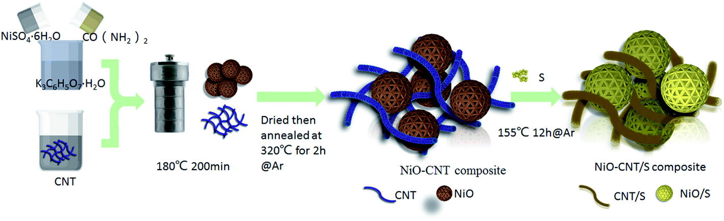 | ||
| Fig. 1 Diagram of the preparation process of NiO–CNT/S composite. | ||
:1) are added into the THF solution. Then, the mixed solution is magnetically stirred until it is clarified at 80 °C. Finally, the Li2S4 solution (3 mg mL−1) is obtained. The whole preparation process is completed in a glove box filled with Ar.2.2 Electrochemical measurements
Cathode materials are prepared via pouring uniform slurry containing 5wt% styrene butadiene rubber (SBR), 5 wt% sodium carboxymethylcellulose (NaCMC), 10 wt% super P carbon black (TIMCAL), and 80 wt% active materials onto the aluminum foil. Subsequently, the obtained electrode films are dried at 65 °C for 10 h in vacuum oven, then punch holes into small circular disc (8 mm diameter). Considering S is about 58.7% of NiO–CNT/S, therefore the calculation results show that the areal sulfur loading in NiO–CNT/S cathode is 2.1 mg cm−2. The 2032-type cell is assembled and sealed in the Ar-filled glovebox by employing lithium as the anode and Celgard 2300 as the membrane separator. The electrolyte contains LiNO3 (1 wt%) and LiTFSI (1 mol L−1) in the 1,2-dimethoxyethane and 1,3-dioxolane mixed solvent with a volume ratio of 1:1. The E/S (electrolyte/sulfur) ratio is 16 μL mg−1, and these parameters are kept same in all the tests. Electrochemical impedance spectroscopy (EIS) and cyclic voltammetry (CV) tests are determined by using an electrochemical workstation (CHI760E, Chenhua, China). Galvanostatic charge/discharge tests are carried out with different rates by using Neware BTS-4000 battery tester.
2.3 Characterization
X-ray diffraction (XRD) of obtained samples are collected by an X-ray diffractometer (X'Pert PRO, PANalytical, Holland) with Cu Ka radiation. Raman spectra are recorded using a Raman spectrometer (XperRam200, Nanobase, Republic of Korea). The morphologies of the samples are collected using scanning electron microscopy (SEM; Sirion200, FEI, USA) equipped with energy disperse spectroscopy (EDS). Elemental compositions and chemical states are determined by X-ray photoelectron spectroscopy (XPS; ESCALAB 250XI, Thermo, USA). Thermogravimetry (TGA; TGA4000, PerkinElmer, USA) is conducted from 25 to 600 °C at a heating rate of 10 °C min−1 under N2 atmosphere.3. Results and discussion
XRD analysis of all samples is carried out to determine the phase composition of the composites, as shown in Fig. 2a. The NiO presents the diffraction characteristic peaks at 2θ = 37.1°, 43.1° and 62.6°, which correspond to the (111), (200) and (220) planes of face-centered cubic structure NiO (JCPDS 89-7130).27 The CNT shows obvious characteristic diffraction peaks at 25.9° and 42.7°, corresponding to the (002) and (001) crystal planes, respectively. The characteristic peaks of CNT and NiO are obviously observed in the NiO–CNT composites, which indicates that the crystal structure of NiO did not change significantly and the structure of CNT was not damaged during the growth of NiO in the CNT-disperse solution. Additionally, because the characteristic peaks of these three composites overlap with the characteristic peaks of elemental S, the characteristic diffraction peaks of CNT and NiO are basically covered, so the characteristic peaks of CNT and NiO could hardly be observed after S perfusion.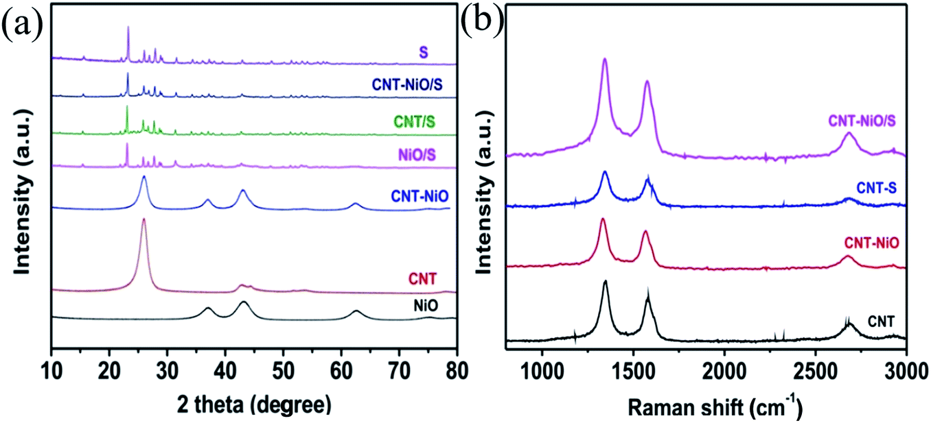 | ||
| Fig. 2 (a) XRD analysis of NiO, CNT, NiO–CNT, NiO/S, CNT/S, NiO–CNT/S and S; (b) Raman spectra of CNT, NiO–CNT, CNT/S and NiO–CNT/S. | ||
Fig. 2b presents the Raman spectra of the CNT, NiO–CNT, CNT/S and NiO–CNT/S samples, which exhibits two distinct characteristic peaks in the interval of 1332–1348 cm−1 and 1567–1584 cm−1, which correspond to the D peak and G peak of CNT respectively, where D peak represents the defects of C atomic lattice in CNT and G peak represents the in-plane stretching vibration of C atomic sp2 hybridization.28 Their intensity ratios (ID/IG) are 1.22, 1.22, 1.25 and 1.29, respectively, with little change in ratio, indicating that the structure of CNT is not significantly changed and destroyed, which played a crucial role in improving the electrochemical performance of S cathode materials.
It can be seen that the morphology of NiO (Fig. 3a) presents a series of honeycomb balls caused by the combination of nanosheets. The microporous and mesoporous structure of NiO can provide a place for the partial loading of S by a certain physical adsorption effect.29 In the NiO/S composite (Fig. 3b), the porous structure of NiO completely disappeared, and just the size of NiO/S was a little bigger than NiO because of S perfusion, indicating that the structure of NiO was not damaged after S perfusion. Fig. 3c shows the staggered arrangement of CNT with a diameter of about 50 nm. As shown in Fig. 3d, it is found that the crisscross CNT are completely wrapped by S after mixing sulfur by the melt-diffusion method. The injection of S made the CNT intertwine with each other, and the ectotheca of the CNT is completely coated by S. If the high conductivity CNT is introduced at this point, not only the remaining S can be loaded, but also the overall conductivity of the positive pole of S can be enhanced. This synergistic effect may result in better electrochemical performance of NiO–CNT/S than NiO/S and CNT/S. The NiO–CNT/S composites (Fig. 3e) reveal that CNT enclosed by S completely, which is about 100 nm in diameter, and no excess sulfur particles on their surface. The energy-dispersive X-ray spectroscopy (EDS) elemental mapping (right side of Fig. 3e) is carried out to analyze the element distribution, which indicates that the sulfur is evenly distributed in the NiO–CNT/S composites. Furthermore, it also reveals the presence of carbon, oxygen, nickel, so that assuring the encapsulation of sulfur successfully.
 | ||
| Fig. 3 SEM images of (a) NiO, (b) NiO/S composite, (c) CNT, (d) CNT/S composite, (e) NiO–CNT/S composite as well as the corresponding EDS element mappings of C, Ni, O and S. | ||
Thermogravimetric analysis (TGA) is tested to determine the sulfur content in obtained samples. It reveals that the sulfur content of the CNT/S and CNT–NiO/S composite is 63.6% and 64.8%, respectively (Fig. 4). Such increasing of the sulfur content may be attributed to some interactions between NiO and sulfur.
 | ||
| Fig. 4 TGA curves of CNT, CNT/S, NiO–CNT/S samples. | ||
The natural interactions between NiO and sulfur can be further analyzed using XPS. It can be seen the presence of Ni, C, O, S elements in NiO–CNT/S composite by their corresponding characteristic peaks and the presence of the S 2p and S 2 s shows the successful recombination of S with NiO–CNT (Fig. 5). The high-resolution XPS spectrum of Ni 2p can be divided into three component peaks corresponding its Ni 2p3/2 (854.6 and 856.9 eV), Ni 2p1/2 (874.2 eV) and satellite peaks (861.8 and 880.2 eV) respectively. Among them, two bifurcation peaks at 854.6 and 856.9 eV (Ni 2p3/2) correspond to Ni2+ and Ni3+, respectively, although corresponding two independently coupled peaks overlap at 874.2 eV (Ni 2p1/2), which implied the existence of mixed valences (Ni2+ and Ni3+).30 After treating with Li2S4, the oxidation and reduction of Li2S4 in the NiO–CNT/S composite result from the redox couple of Ni2+/Ni3+, which contributes to controlling the polysulfide dissolution by the chemical adsorption. Additionally, two characteristic peaks of S 2p3/2 are found in 164.3 and 163.2 eV, which ascribed to the bridging S and terminal S, respectively.31 Meanwhile, the peak appeared in 170.0 eV can be explained into two parts, one is strong interaction between NiO and sulfur, the other one is high-valence sulfates of thiosulfate and polythionate.32
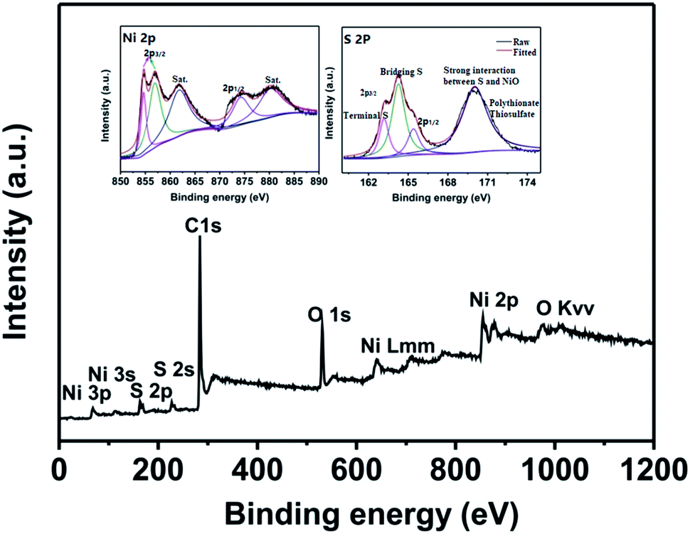 | ||
| Fig. 5 XPS spectra of the NiO–CNT/S composite and high-resolution Ni 2p and S 2p (inset). | ||
Fig. 6a shows the typical cyclic voltammetry (CV) curves of the LSBs based on NiO–CNT/S cathodes to analyze the electrochemical performance, which are performed with a scan rate of 0.1 mV s−1 range from 1.7 to 2.8 V (vs. Li/Li+). Two reduction peaks at around 2.27 V and 2.04 V in the CV of NiO–CNT/S composites are more noticeable, which implied that the reductions of S in the discharge process are carried out in several parts. High potential 2.27 V corresponds to the reduction of S8 into long-chain polysulfide lithium (Li2Sx, 4 ≤ x ≤ 8), and low potential 2.04 V corresponds to the further reduction of long-chain polysulfide lithium (Li2S/Li2S2) insoluble in organic electrolyte.33 One oxidation peak corresponds to the oxidation of the long-chain polysulfides to the Li2S2 & Li2S. Fig. 6b presents the constant current charge–discharging curves, which indicates a two-voltage plateau in keeping with the CVs results. It can be observed that the initial specific capacity of NiO/S, CNT/S and NiO–CNT/S cathodes at 0.1C is 468, 955 and 1072 mA h g−1, respectively.
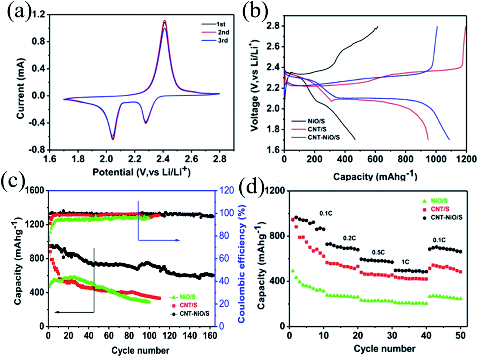 | ||
| Fig. 6 (a) CV curves of NiO–CNT/S composites; (b) charge/discharge curves of NiO/S, CNT/S and NiO–CNT/S cathodes at 0.1C; (c) coulombic efficiencies and cycling performances of NiO/S, CNT/S and NiO–CNT/S cathodes at 0.1C; (d) rate capabilities of NiO/S, CNT/S and NiO–CNT/S cathodes. | ||
Fig. 6c displays the coulombic efficiency and cycling stability of the LSBs at 0.1C. Although the CNT/S cathode deliver a good initial discharge capacity (955 mA h g−1), its discharge capacity attenuates to ∼580 mA h g−1 after 10 cycles. A high capacity decay will occur in the absence of NiO, demonstrating the serious polysulfides shuttle. After 100 cycles, the discharge capacities of the NiO/S, CNT/S and NiO–CNT/S composites fades to 288, 358, 746 mA h g−1 with the capacity decline rate of 0.385%, 0.623%, 0.216% per cycle, respectively. Moreover, the NiO–CNT/S cathode exhibits stable cycle ability (609 mA h g−1) over 160 cycles and presents an ultrahigh coulombic efficiency (∼100%) and lower capacity decline in comparison to that of NiO/S and CNT/S. This proves once again that both CNT and NiO in NiO–CNT/S composites play a common role in promoting the electrochemical performance of S electrode. On the one hand, the high conductivity of CNT can shorten the ion transmission path in electrochemical reaction. On the other hand, the strong chemical bond between NiO and lithium polysulfide inhibits the dissolution of polysulfide ions and effectively alleviates the “shuttle effect”, resulting in reducing the loss of active substances.
Fig. 6d reveals the rate performance of the cathodes based on the NiO/S, CNT/S and NiO–CNT/S cathodes at different current densities of 0.1, 0.2, 0.5 and 1C, and then back to 0.1C. It can be found that the discharge capacity of the NiO–CNT/S cathode declines steadily with increasing of current densities, and their reversible capacity is about 850, 680, 560 and 480 mA h g−1, respectively. Furthermore, the reversible capacity is recovered to 670 mA h g−1 when the current density is back to 0.1C, demonstrating a stable performance and excellent capacity. In contrast, the discharge capacities of NiO/S and CNT/S decline quickly with the increasing current densities.
In order to further investigate the dynamics of lithium insertion and extraction in the LSBs, as shown in Fig. 7, EIS measurements of NiO/S, CNT/S and NiO–CNT/S cathodes are performed. The impedance plot can be quantitatively analyzed based on the equivalent circuit of the cells (inset of Fig. 7), as detailed in Table 1, where Re and Rct respectively represents the solution resistance and charge-transfer resistance. It is clear that the NiO–CNT/S cathode displays the lowest value (4.279 Ω cm−2) in comparison with that of CNT/S (4.695 Ω cm−2) and NiO/S (5.422 Ω cm−2), which attributed to the synergistic effect in the NiO–CNT/S hybrid structure. The semicircles in medium frequency region are related to the Rct, which stand for the kinetic resistance of the electrochemical reaction at the electrode/electrolyte interface.34 The NiO–CNT/S cathode (52.21 Ω cm−2) also displays lower Rct than that of CNT/S (253.13 Ω cm−2) and NiO/S (136.45 Ω cm−2), implying that the hybrid structure of NiO–CNT/S is conducive to faster charge transfer of the cathodes.
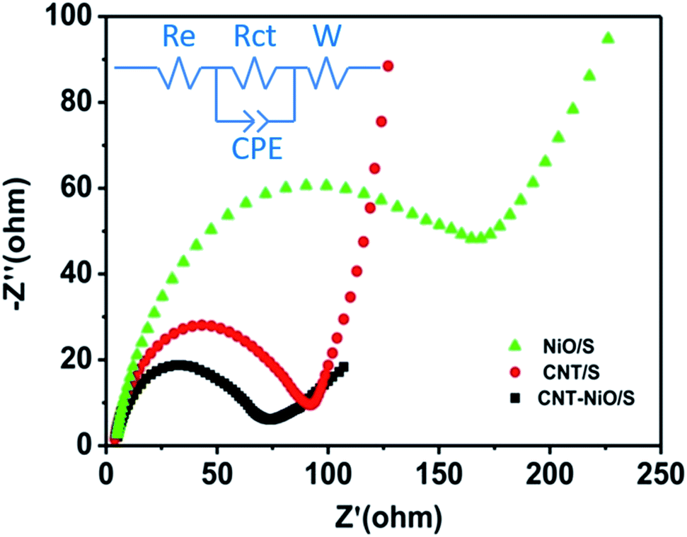 | ||
| Fig. 7 EIS of the NiO/S, CNT/S and NiO–CNT/S cathodes between 1.7 and 2.8 V. | ||
| Parameters | Cathodes | ||
|---|---|---|---|
| NiO/S | CNT/S | NiO–CNT/S | |
| Re (Ω cm−2) | 5.422 | 4.695 | 4.279 |
| Rct (Ω cm−2) | 136.45 | 253.13 | 52.21 |
4. Conclusion
In summary, a novel NiO–CNT/S composite was prepared as the cathode material of LSBs. The developed NiO–CNT/S composites present higher cycling stability, lower capacity decline and higher capacity retention in comparison with that of pure CNT and NiO. This may be attributed to that the S and lithium polysulfide are subjected to stronger acting force under the double adsorption of CNT and NiO (physical adsorption and chemical adsorption), which reduces the loss of active substances and enables NiO–CNT/S to have better electrochemical performance. This design idea offers a novel approach to further construct the low-cost, high-energy, long-life LSBs.Conflicts of interest
The authors declare no competing financial interest.Acknowledgements
This work was financially supported by the Special Project for Guangxi Science and Technology Bases and Talents (No. AD19110148, AD19910163), Natural Science Foundation of Guangxi (2020GXNSFBA297122), Doctoral Foundation of Guangxi University of Science and Technology (No. 19Z13, 18Z13, 19Z12), Middle-aged and Young Teachers' Basic Ability Promotion Project of Guangxi (No. 2020KY08014), National Basic Research Program of China (No. 2015CB258400), and the National Key Research and Development Program of China (No. 2016YFB0700700). We also thank the testing center of Huazhong University of Science and Technology for SEM, XRD, TGA, and XPS measurements.References
- J. Zheng, G. Ji, X. Fan, J. Chen, L. Qin, H. Wang, Y. Yang, K. C. DeMella, S. R. Raghavan and C. Wang, High-Fluorinated Electrolytes for Li-S Batteries, Adv. Energy Mater., 2019, 9, 1803774 CrossRef.
- Q. Xie, A. Zheng, C. Xie, W. Fu, S. Wu, Y. Zhang and P. Zhao, Graphene functionalized attapulgite/sulfur composite as cathode of lithium–sulfur batteries for energy storage, Micropor. Mesopor. Mater., 2016, 224, 239–244 CrossRef CAS.
- M. R. Sovizi and Z. Fahimi, Honeycomb polyaniline-dodecyl benzene sulfonic acid (hPANI-DBSA)/sulfur as a new cathode for high performance Li–S batteries, J. Taiwan Inst. Chem. Eng., 2018, 86, 270–280 CrossRef CAS.
- A. Ghosh, M. S. Garapati, A. P. Vijaya Kumar Saroja and R. Sundara, Polar Bilayer Cathode for Advanced Lithium-Sulfur Battery: Synergy Between Polysulfide Conversion and Confinement, J. Phys. Chem. C, 2019, 123, 10777–10787 CrossRef CAS.
- X. Liang and L. F. Nazar, In Situ Reactive Assembly of Scalable Core-Shell Sulfur-MnO2 Composite Cathodes, ACS Nano, 2016, 10, 4192–4198 CrossRef CAS PubMed.
- S. Deng, Y. Yan, L. Wei, T. Li, X. Su, X. Yang, Z. Li and M. Wu, Amorphous Al2O3 with N-Doped Porous Carbon as Efficient Polysulfide Barrier in Li–S Batteries, ACS Appl. Energy Mater., 2019, 2, 1266–1273 CrossRef CAS.
- M. Wang, L. Fan, X. Wu, Y. Qiu, B. Guan, Y. Wang, N. Zhang and K. Sun, Metallic NiSe2 Nanoarray Towards Ultralong life and Fast Li2S Oxidation Kinetic of Li-S Batteries, J. Mater. Chem. A, 2019, 7, 15302–15308 RSC.
- Y. Guan, X. Liu, N. Akhtar, A. Wang, W. Wang, H. Zhang, J. Suntivich and Y. Huang, Cr2O3 Nanoparticle Decorated Carbon Nanofibers Derived from Solid Leather Wastes for High Performance Lithium-Sulfur Battery Separator Coating, J. Electrochem. Soc., 2019, 166, A1671–A1676 CrossRef CAS.
- X. Gu, C. Lai, F. Liu, W. Yang, Y. Hou and S. Zhang, A conductive interwoven bamboo carbon fiber membrane for Li–S batteries, J. Mater. Chem. A, 2015, 3, 9502–9509 RSC.
- K. Hori, K. Hasegawa, T. Momma and S. Noda, Volumetric Discharge Capacity 1 A h cm–3 Realized by Sulfur in Carbon Nanotube Sponge Cathodes, J. Phys. Chem. C, 2019, 123, 3951–3958 CrossRef CAS.
- X. Wen, K. Xiang, Y. Zhu, L. Xiao, H. Liao, X. Chen and H. Chen, Nb2O5-Decorated Nitrogen-Doped Carbon Nanotube Microspheres for Highly Efficient Sulfur Confinement in Lithium–Sulfur Batteries, Ind. Eng. Chem. Res., 2019, 58, 8724–8733 CrossRef CAS.
- Z. Du, X. Chen, W. Hu, C. Chuang, S. Xie, A. Hu, W. Yan, X. Kong, X. Wu, H. Ji and L. J. Wan, Cobalt in Nitrogen-Doped Graphene as Single-Atom Catalyst for High-Sulfur Content Lithium-Sulfur Batteries, J. Am. Chem. Soc., 2019, 141, 3977–3985 CrossRef CAS PubMed.
- J. Q. Huang, J. Huang, W. G. Chong, J. Cui, S. Yao, B. Huang and J. K. Kim, Graphene/RuO2 nanocrystal composites as sulfur host for lithium-sulfur batteries, J. Energy Chem., 2019, 35, 204–211 CrossRef.
- Q. Wang, Z. B. Wang, C. Li and D. M. Gu, High sulfur content microporous carbon coated sulfur composites synthesized via in situ oxidation of metal sulfide for high-performance Li/S batteries, J. Mater. Chem. A, 2017, 5, 6052–6059 RSC.
- S. Wang, K. Zou, Y. Qian, Y. Deng, L. Zhang and G. Chen, Insight to the synergistic effect of N-doping level and pore structure on improving the electrochemical performance of sulfur/N-doped porous carbon cathode for Li-S batteries, Carbon, 2019, 144, 745–755 CrossRef CAS.
- Y. Choi, N. Yoon, N. Kim, C. Oh, H. Park and J. K. Lee, Discrete hollow carbon spheres derived from pyrolytic copolymer microspheres for Li-S batteries, J. Electrochem. Soc., 2019, 166, A5099–A5108 CrossRef CAS.
- Y. Yang, H. Xu, S. Wang, Y. Deng, X. Qin, X. Qin and G. Chen, N-doped carbon-coated hollow carbon nanofibers with interspersed TiO2 for integrated separator of Li-S batteries, Electrochim. Acta, 2019, 297, 641–649 CrossRef CAS.
- Y. Guo, J. Li, R. Pitcheri, J. Zhu, P. Wen and Y. Qiu, Electrospun Ti4O7/C conductive nanofibers as interlayer for lithium-sulfur batteries with ultra long cycle life and high-rate capability, Chem. Eng. J., 2019, 355, 390–398 CrossRef CAS.
- C. Du, J. Wu, P. Yang, S. Li, J. Xu and K. Song, Embedding S@TiO2 nanospheres into MXene layers as high rate cyclability cathodes for lithium-sulfur batteries, Electrochim. Acta, 2019, 295, 1067–1074 CrossRef CAS.
- T. Liu, X. Sun, S. Sun, Q. Niu, H. Liu, W. Song, F. Cao, X. Li, T. Ohsaka and J. Wu, A robust and low-cost biomass carbon fiber@SiO2 interlayer for reliable lithium-sulfur batteries, Electrochim. Acta, 2019, 295, 684–692 CrossRef CAS.
- D. Yan, Y. Huang, C. Fan, X. Wang, J. Yan, H. Lin, D. Jia, J. Zong, W. Wang and G. Wu, Entrapment of polysulfides by Al2O3 modified separator for high energy Li–S redox flow batteries, J. Alloy Compd., 2019, 770, 1229–1236 CrossRef CAS.
- S. Tu, X. Zhao, M. Cheng, P. Sun, Y. He and Y. Xu, Uniform Mesoporous MnO2 Nanospheres as a Surface Chemical Adsorption and Physical Confinement Polysulfide Mediator for Lithium–Sulfur Batteries, ACS Appl. Mater. Inter., 2019, 11, 10624–10630 CrossRef CAS PubMed.
- Q. Qu, T. Gao, H. Zheng, Y. Wang, X. Li, X. Li, J. Chen, Y. Han, J. Shao and H. Zheng, Strong Surface-Bound Sulfur in Conductive MoO2 Matrix for Enhancing Li-S Battery Performance, Adv. Mater. Inter., 2015, 2, 1500048 CrossRef.
- X. Liang, C. Y. Kwok, F. Lodi-Marzano, Q. Pang, M. Cuisinier, H. Huang, C. J. Hart, D. Houtarde, K. Kaup, H. Sommer, T. Brezesinski, J. Janek and L. F. Nazar, Tuning Transition Metal Oxide-Sulfur Interactions for Long Life Lithium Sulfur Batteries: The “Goldilocks” Principle, Adv. Energy Mater., 2016, 6, 1501636 CrossRef.
- M. Zheng, Y. Chi, Q. Hu, H. Tang, X. Jiang, L. Zhang, S. Zhang, H. Pang and Q. Xu, Carbon nanotube-based materials for lithium–sulfur batteries, J. Mater. Chem. A, 2019, 7, 17204–17241 RSC.
- S. Abualela, X. Lv, Y. Hu and M. D. Abd-Alla, NiO nanosheets grown on carbon cloth as mesoporous cathode for High-performance lithium-sulfur battery, Mater. Lett., 2020, 268, 127622 CrossRef CAS.
- Q. Zhang, Y. Wang, Z. W. Seh, Z. Fu, R. Zhang and Y. Cui, Understanding the Anchoring Effect of Two-Dimensional Layered Materials for Lithium-Sulfur Batteries, Nano Lett., 2015, 15, 3780–3786 CrossRef CAS PubMed.
- S. Choudhury, M. Zeiger, P. Massuti-Ballester, S. Fleischmann, P. Formanek, L. Borchardt and V. Presser, Carbon onion–sulfur hybrid cathodes for lithium–sulfur batteries, Sustain. Energ. Fuels, 2018, 1, 84–94 RSC.
- H. Li, S. Gu, B. Tao, Y. Xie, F. Guo, S. Zhang, B. Liu, J. Liu, W. Zhang and H. Chang, Highly wrinkled NiO nanosheet-based hierarchical structure/reduced fluorographene composite for enhanced performance of lithium-sulfur battery, J. Taiwan Inst. Chem. Eng., 2020, 111, 17–23 Search PubMed.
- N. Jiang, Q. Tang, M. Sheng, B. You, D. E. Jiang and Y. Sun, Nickel sulfides for electrocatalytic hydrogen evolution under alkaline conditions: a case study of crystalline NiS, NiS2, and Ni3S2 nanoparticles, Catal. Sci. Technol., 2016, 6, 1077–1084 RSC.
- S. Rehman, T. Tang, Z. Ali, X. Huang and Y. Hou, Integrated Design of MnO2@Carbon Hollow Nanoboxes to Synergistically Encapsulate Polysulfides for Empowering Lithium Sulfur Batteries, Small, 2017, 13, 1700087 CrossRef PubMed.
- X. Wang, G. Li, J. Li, Y. Zhang, A. Wook, A. Yu and Z. Chen, Structural and chemical synergistic encapsulation of polysulfides enables ultralong-life lithium–sulfur batteries, Energy Environ. Sci., 2016, 9, 2533–2538 RSC.
- Y. Zhang, Y. Zhao and Z. Bakenov, A simple approach to synthesize nanosized sulfur/graphene oxide materials for high-performance lithium/sulfur batteries, Ionics, 2014, 20, 1047–1050 CrossRef CAS.
- Z. Liu, J. Li, J. Xiang, S. Cheng, H. Wu, N. Zhang, L. Yuan, W. Zhang, J. Xie, Y. Huang and H. Chang, Hierarchical nitrogen-doped porous graphene/reduced fluorographene/sulfur hybrids for high-performance lithium–sulfur batteries, Phys. Chem. Chem. Phys., 2017, 19, 2567–2573 RSC.
Footnote |
| † Electronic supplementary information (ESI) available. See DOI: 10.1039/d1ra00216c |
| This journal is © The Royal Society of Chemistry 2021 |