DOI:
10.1039/D1RA00195G
(Paper)
RSC Adv., 2021,
11, 10300-10308
Fabrication of TiO2/Fe2O3/CdS systems: effects of Fe2O3 and CdS content on superior photocatalytic activity
Received
9th January 2021
, Accepted 23rd February 2021
First published on 11th March 2021
Abstract
A heterostructured material of CdS and Fe2O3 nanoparticle-modified TiO2 nanotube array (NTA) photoelectrode (TiO2/Fe2O3/CdS) is reported in this work. TiO2/Fe2O3 was prepared by annealing TiO2 NTAs pre-loaded with Fe(OH)3, which was uniformly clung to TiO2 NTAs using sequential chemical bath deposition (S-CBD). Subsequently, CdS nanoparticles were deposited on TiO2/Fe2O3 using the successive ion layer adsorption and reaction (SILAR) technique. Three-dimensional (3D) TiO2/Fe2O3/CdS samples generated a photocurrent of approximately 4.92 mA cm−2, with a photoconversion efficiency of 4.36%, which is more than 20 times higher than that of bare TiO2 NTAs (0.22%) and 6 times that of TiO2/Fe2O3 (0.71%). The photocatalytic activity was evaluated by the degradation of p-nitrophenol (PNP) under visible light (λ > 420 nm). The TiO2/Fe2O3/CdS exhibited the best photocatalytic activity among all samples. Almost all PNP was degraded by TiO2/Fe2O3/CdS within 120 min. The enhancement of photocatalytic activity could be attributed to the promoted photo-induced electron and hole separation and migration on the basis of photoluminescence spectra, photocurrent measurements, and open-circuit photovoltage responses. In addition, the newly synthesized TiO2/Fe2O3/CdS can maintain high photocatalytic efficiency for five reuse cycles. Our findings provide a new idea for the low cost synthesis of high performance photocatalysts for the photodegradation of organic pollutants in aqueous solution.
1. Introduction
TiO2 is very attractive due to its fascinating features such as plentiful polymorphs, good chemical and thermal stability, and excellent electronic and optical properties.1 TiO2 nanotubes have a larger specific surface area and exchange capacity, as well as higher surface energy and extremely strong adsorption capacity compared with other TiO2 nanomaterials.2,3 Furthermore the conductive substrate of Ti is closely connected with the highly ordered porous nanotube, which accelerates the separation of photogenerated charges and inhibits their recombination, so the photoelectric efficiency is improved. However, TiO2 is active only under near-ultraviolet irradiation, only around 4% of the incident solar spectrum energy, due to its wide band gap energy of 3.0–3.2 eV.4,5
Numerous attempts were made to extend the light absorption of TiO2 to the visible light range, which accounts for around 48% of the incident solar energy.6 Fe2O3 is considered to be one of the best co-catalyst candidates due to its appropriate band gap (Eg ∼ 2.2 eV) for solar light harvesting, good photochemical stability, earth abundance, nontoxicity and low cost.7 For example, Kuang et al.5 reported the fabrication, characterization and photoelectrochemical properties of Fe2O3 modified TiO2 nanotube arrays. Moniz et al.8 demonstrated that the decoration of Fe2O3 nanoclusters on TiO2 leads to better charge separation and enhanced photocatalytic activity. Xia et al.9 prepared novel α-Fe2O3@TiO2 core/shell nanocomposites with improved photocatalytic activity in the visible light region. X. Lv et al.3 designed Fe2O3@TiO2 nanotube composite anodes for lithium-ion batteries. Sun et al.10 demonstrated the effect of surface Fe2O3 clusters on the photocatalytic activity of TiO2 for phenol degradation in water. Yao et al.7 proved that Fe2O3 nanothorns sensitized two-dimensional TiO2 nanosheets with highly efficient solar energy conversion. Cao et al.11 synthesized Fe2O3–B–TiO2 superstructures with highly promoted photocatalytic activity and recyclability.
Previous studies have shown that co-sensitizing TiO2 with different nanocrystals such as CdS/ZnIn2S4,4 CdTe/Mn–CdS,12 CdS–Mn/MoS2/CdTe,13 CdS/CuInS2/Au,14 Mn–CdS/MoS2,15 and CdS-based photocatalysts16–18 can extend the light absorption to the infrared range, and more importantly align the energy bands of the semiconductor. In summary, combining TiO2 with Fe2O3 and CdS semiconductors could largely improve the photocatalytic activity of the co-sensitized electrode, as the energy levels of Fe2O3 (bandgap ∼2.2 eV), CdS (∼2.4 eV), and TiO2 (3.0–3.2 eV) are well suitable to one another, which benefits the separation of e−–h+ pairs.15
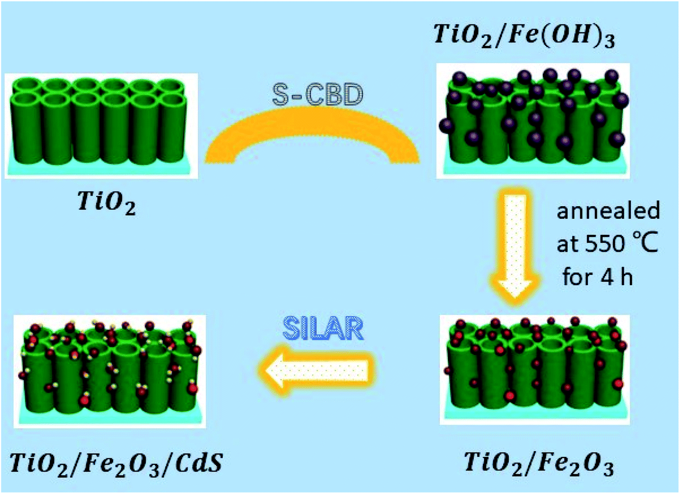
Herein, we fabricated TiO2/Fe2O3/CdS ternary heterostructures using a facile S-CBD method coupled with SILAR (Fig. 1). So far, to our knowledge, Ruiyang Yin et al.19 demonstrated a CdS/α-Fe2O3/TiO2 nanorod array for efficient photoelectrochemical (PEC) water oxidation that exhibits an improved photocurrent density of 0.62 mA cm−2, while the photocurrent density of the present work reaches 4.92 mA cm−2 with a 20 fold photoconversion efficiency increase compared to bare TiO2 photoanodes.
 |
| | Fig. 1 Schematic illustration of the construction of TiO2/Fe2O3/CdS heterostructures. | |
2. Experimental
2.1. Materials and methods
Titanium foil (99.8%, 0.127 mm thick) was purchased from Aldrich (Milwaukee, WI). Other reagents were of analytical grade. Double distilled water was used throughout the experiments. Titanium foil was cut into 1.0 cm × 3.5 cm strips. The strips were ultrasonically cleaned in acetone and ethanol each for 5 min, respectively. The cleaned titanium strips were anodized at a constant potential of 25 V in an electrolyte containing 0.1 M NaF and 0.5 M NaHSO4 at room temperature for 3 h in a two electrode configuration with a platinum cathode and the Ti strip as the anode. After oxidation, the prepared TiO2 NTAs by an anodic oxidation process were directly successively immersed in NaOH, H2O, FeCl3, and H2O for 5 min each. Fe(OH)3 was then successfully deposited onto the TiO2 NTAs by S-CBD.20 The immersion cycle was repeated five times. The amount of loaded Fe(OH)3 was controlled by varying the FeCl3 concentration at 0.01, 0.02, 0.05, 0.08, 0.10, 0.20, and 0.30 M, respectively. The TiO2 NTAs loaded with Fe(OH)3 were annealed for crystallization at 550 °C for 4 h to obtain the Fe2O3-modified TiO2 NTA photocatalysts. Second, the synthetic TiO2/Fe2O3 was successively immersed in two different solutions for 1 min each: first in ethanol solution, 0.05 mol L−1 Cd(NO3)2 as the cation source, and then in 0.05 mol L−1 Na2S in methanol/water (7![[thin space (1/6-em)]](https://www.rsc.org/images/entities/char_2009.gif) :3 v/v). Following each immersion, the composite was rinsed for 2 min or longer with pure ethanol and methanol, respectively, to remove excess precursors and dried before the next dipping.15,21 The loading amount of the deposit was controlled by adjusting the number of immersion cycles; here, 1, 3, 5, 7 and 9 cycles were chosen for deposition. After washing several times with distilled water, the resulting TiO2/Fe2O3/CdS heterostructure was heated under a nitrogen atmosphere at 300 °C for 2 h.
:3 v/v). Following each immersion, the composite was rinsed for 2 min or longer with pure ethanol and methanol, respectively, to remove excess precursors and dried before the next dipping.15,21 The loading amount of the deposit was controlled by adjusting the number of immersion cycles; here, 1, 3, 5, 7 and 9 cycles were chosen for deposition. After washing several times with distilled water, the resulting TiO2/Fe2O3/CdS heterostructure was heated under a nitrogen atmosphere at 300 °C for 2 h.
2.2. Photoelectrochemical measurements and structural characterization
The photocurrent measurements were conducted on a CHI-660C electrochemical system (Shanghai Chenhua Instrument Co. Ltd., China) using a standard three electrode cell with a working electrode, a platinum wire counter electrode, and a saturated calomel electrode (SCE) reference electrode. A solution containing 1 M KOH was used as the electrolyte. The sample (TiO2/Fe2O3/CdS) was applied as the working electrode.22 A Xe lamp (CHF-XQ-500W, Beijing Changtuo Co. Ltd.) served as the light source. The incident light was filtered to match the AM 1.5G spectrum with an intensity of 100 mW cm−2 as measured with a radiometer (OPHIR, Littleton, CO). Scanning electron microscopy (SEM) images were recorded on a field-emission scanning electron microscope (SEM, JSM-6700F). Transmission electron microscopy (TEM) images and selected area electron diffraction (SAED) patterns were recorded on a JEOL JEM 2100 high resolution transmission electron microscope. An energy dispersive X-ray (EDX) spectrometer fitted to an electron microscope was used for elemental analysis. X-ray diffraction (XRD) patterns were recorded for identification of crystal structures of the samples with an X-ray diffractometer (XRD, M21X, MAC Science Ltd., Japan) employing Cu Kα radiation (λ = 1.54060 Å). Light absorption properties were examined using UV-vis diffuse reflectance spectra (DRS, SHIMADZU, UV-2450) within a wavelength range of 200–800 nm. Photoluminescence (PL) spectra were recorded using a Hitachi F-4600 fluorescence spectrophotometer (Japan).
2.3. Photocatalytic degradation of PNP
The photocatalytic decomposition of PNP solution under visible light was performed to investigate the photocatalytic activities of TiO2/Fe2O3 and TiO2/Fe2O3/CdS in comparison with those of the pure TiO2 NTAs. For the test, the incident light intensity was adjusted to 100 mW cm−2 through an IR cut filter (λ ≥ 800 nm) and a UV cut filter (λ < 400 nm) from a 500 W Xe lamp. The PNP solution (0.1 L, 20 mg L−1) was illuminated for 2 h under magnetic stirring. The characteristic absorption of PNP at 316 nm, analysed using a UV-vis spectrophotometer (CARY 300 Conc), was used to monitor the photocatalytic degradation. The degradation of the organic pollutant was determined following the Beer–Lambert law for the absorption band with the maximum at 316 nm for PNP. All the measurements were performed at room temperature.
2.4. Analysis of the photodegradation mechanism
Hydroxyl radicals (˙OH) produced on the sample surface under AM 1.5G illumination were detected by PL analysis using terephthalic acid (TA), as the probe molecule.23,24 Experimental steps were performed in 5 × 10⁻⁴ mol L−1 TA and 2 × 10⁻³ mol L−1 NaOH solutions. The change of ˙OH concentration during the procedure was monitored by determining the fluorescence emission intensity with an excitation wavelength of 320 nm.
3. Results and discussion
3.1. Characterization of the TiO2/Fe2O3/CdS
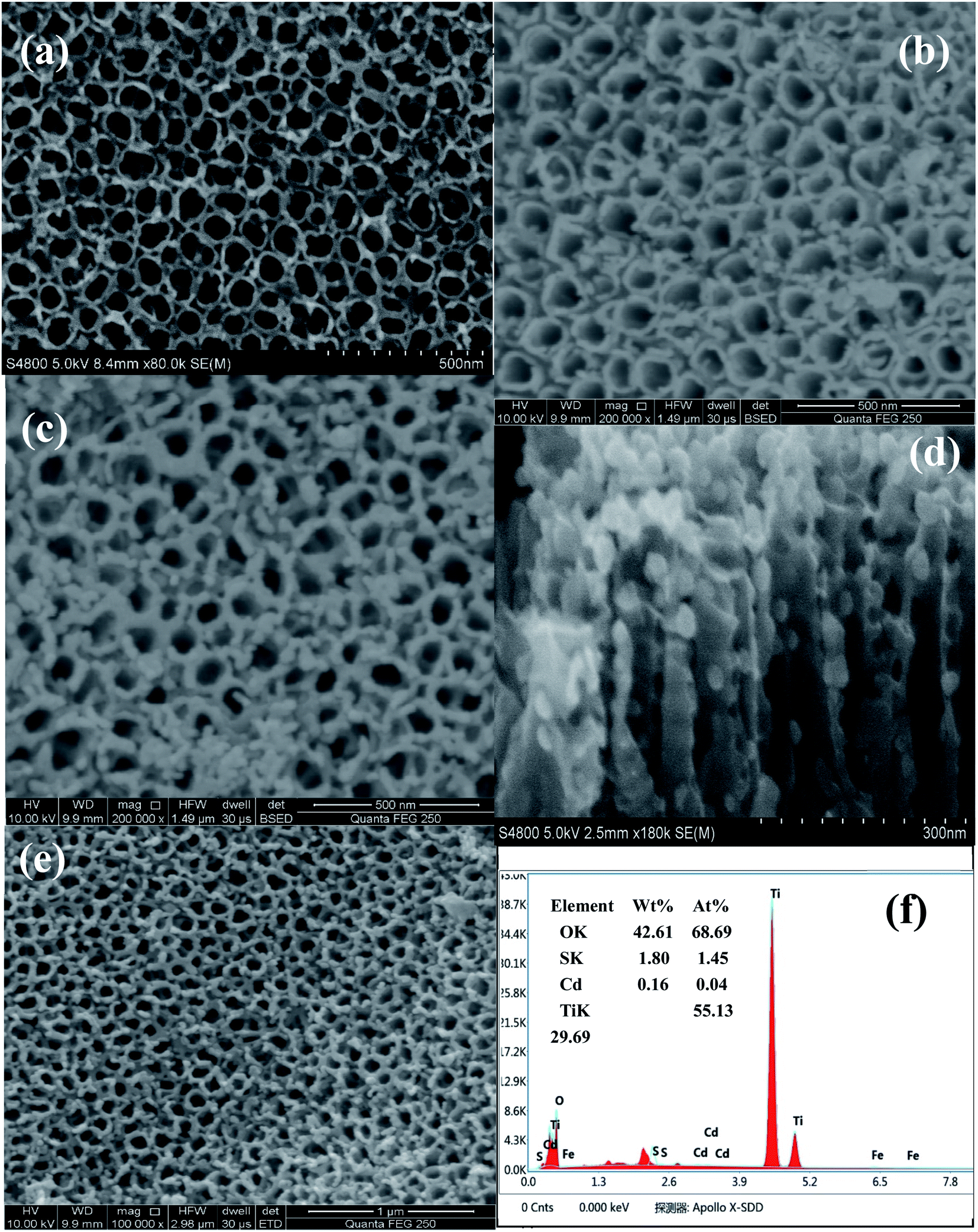
Fig. 2 shows the SEM images of TiO2 with/without the deposition of Fe2O3 and CdS. As shown in Fig. 2b and c, the surface of the TiO2 NTAs is homogeneously covered with Fe2O3 and CdS nanoparticles. Fig. 2d displays the cross-sectional images of TiO2/Fe2O3/CdS. The bare TiO2 NTAs are smooth and clean (Fig. 2a). The Fe2O3 nanoparticles are distributed mainly on the top surface and interstices of the NTAs (Fig. 2b). After 9 cycles of CdS adsorption onto the TiO2/Fe2O3 heterostructure, the surface of the material (Fig. 2c and e) becomes a little rougher than undecorated TiO2/Fe2O3 (Fig. 2b), and the gap between TiO2 NTAs almost disappears owing to the filling of Fe2O3 and CdS nanoparticles. No obvious blocking of the entrances is observed and the porosity of the structure is more beneficial for the adsorption process.25 Fig. 2f shows the EDS of the TiO2/Fe2O3/CdS. EDS analysis confirms the successful attachment of the CdS and Fe2O3.
 |
| | Fig. 2 SEM of TiO2 nanotube arrays (a), top view of the TiO2/Fe2O3 heterostructure (b) and TiO2/Fe2O3/CdS heterostructure (c), cross-sectional view of the TiO2/Fe2O3/CdS heterostructure (d), SEM images of the TiO2/Fe2O3/CdS heterostructure under different magnification (e), and the corresponding EDS of the TiO2/Fe2O3/CdS heterostructure (f). | |
As depicted in the TEM image in Fig. 3a, it was observed that the TiO2/Fe2O3/CdS product is composed of many aggregated nanocrystals. The detailed microscopic characterization of the TiO2/Fe2O3/CdS heterostructure is performed using HRTEM images as displayed in Fig. 3b. The measured lattice spacings are consistent with the d-spacings of TiO2 (0.297 nm, JCPDS 21-1272), CdS (0.28 nm, JCPDS 80-0019) and Fe2O3 (0.27 nm, JCPDS 72-469), respectively.7,26 The nanocrystalline material structure is confirmed with XRD analysis (Fig. 3c) and the SAED pattern (Fig. 3d) which further indicates the presence of TiO2, Fe2O3 and CdS.
 |
| | Fig. 3 TEM (a) and HRTEM images (b), XRD patterns (c) and SAED pattern (d) of the as-synthesized CdS/Fe2O3/TiO2 composites. | |
3.2. Optimization of the TiO2/Fe2O3/CdS
Fe2O3 nanoparticles were firstly immobilized on TiO2 NTAs by immersing the TiO2 in FeCl3 solution from 0.01 mol L−1 to 0.3 mol L−1. Fig. 4A indicates that the photocurrent response varies with Fe content, and the maximum photocurrent (1.89 mA cm−2, curve g) is obtained on the TiO2/Fe2O3 NTAs with 0.2 mol L−1 Fe, which is 7.56 times that achieved on pure TiO2 NTAs (0.25 mA cm−2, curve a).
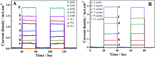 |
| | Fig. 4 (A) Photocurrent responses in light on–off process of (a) unmodified TiO2 nanotubes and (b–h) TiO2/Fe2O3 nanotubes with increasing Fe content. (B) Short-circuit photocurrent density versus time plotted (0 V versus SCE) for TiO2/Fe2O3/CdS with different cycles of CdS. | |
Further immobilization of CdS nanoparticles on the TiO2/Fe2O3 NTAs resulted in a dramatic increase of the photocurrent up to 4.92 mA cm−2 by 9 SILAR cycles (Fig. 4B, curve e). The photocurrent density increases first and then decreases (curve f) with increasing CdS loading on the electrodes. Over-loading of CdS nanoparticles beyond 9 SILAR cycles formed a significant aggregation, which is less efficient in absorption spectra as compared to un-aggregated smaller size nanocrystallites, resulting in a decrease in photocurrent.27
3.3. Photoelectrochemical behavior evaluation
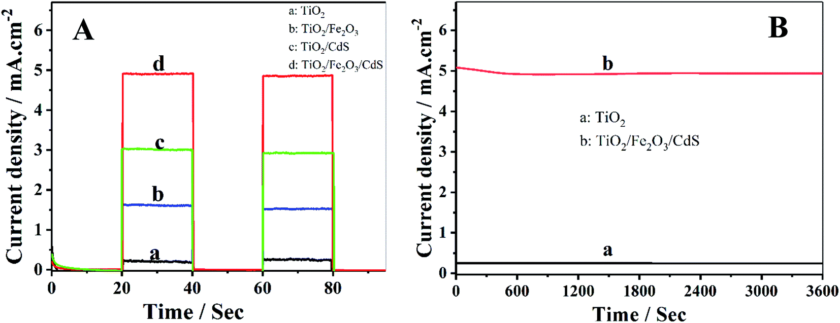
Photocurrent density–time characteristics of the samples were investigated in an electrolyte containing 0.35 mol L−1 Na2SO3 and 0.24 mol L−1 Na2S to examine the photoelectrochemical properties. The TiO2/Fe2O3/CdS NTAs show the best performances with a photocurrent density of 4.92 mA cm−2 (curve d) which is much higher than those of the pure TiO2 (0.25 mA cm−2, curve a), TiO2/Fe2O3 (1.89 mA cm−2, curve b) and TiO2/CdS (3.02 mA cm−2, curve c) (see Fig. 5A). Fig. 5B shows the time-dependent photocurrent responses of the TiO2/Fe2O3/CdS and unmodified TiO2 NTAs under illumination with 100 mW cm−2 visible light. Both show a high stability, and the photocurrent decreases by 1.04% within 1 h.
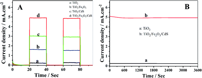 |
| | Fig. 5 (A) Photocurrent responses of (a) TiO2, (b) TiO2/Fe2O3, (c) TiO2/CdS and (d) TiO2/Fe2O3/CdS; (B) time-dependent photocurrent response of (a) unmodified TiO2 and (b) TiO2/Fe2O3/CdS. | |
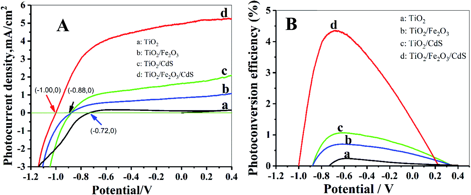
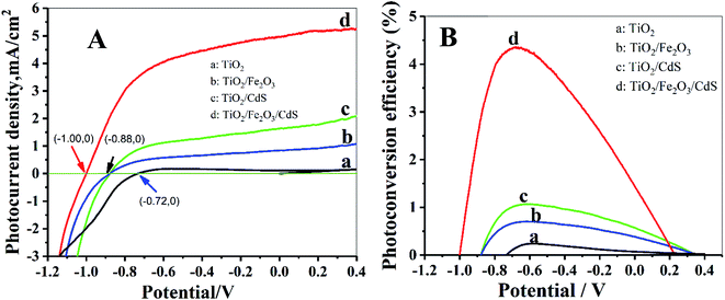
The photoelectric performance of the TiO2/Fe2O3/CdS is further investigated by the photocurrent–applied potential (J–V) relationship. As illustrated in Fig. 6A, the photocurrent response increases significantly on the TiO2/Fe2O3/CdS, even at a potential of 0 V. The open circuit potential, Voc, which corresponds to the difference between the apparent Fermi levels of the working electrode and the reference electrode, is around −1.00 V for the TiO2/Fe2O3/CdS, which is greater than that obtained with TiO2/Fe2O3 and TiO2/CdS (Voc ≈ −0.88 V) and pure TiO2 NTAs (Voc ≈ −0.72 V), demonstrating a shift in the Fermi level to a more negative potential in the TiO2/Fe2O3/CdS composite system, which can improve the photogenerated electron–hole separation and suppress the recombination of photogenerated charge carriers.28 Fig. 6B displays the corresponding photoconversion efficiency calculated using eqn (1):26
| | |
η (%) = jp[Eqrev − |Eapp|] × 100/(I0)
| (1) |
where
jp is the photocurrent density (mA cm
−2),
jpEqrev is the total power output,
jp|
Eapp| is the power input, and
I0 is the power density of incident light (100 mW cm
−2).
Eqrev equals 1.23 V, which is the standard potential for the water splitting reaction. The applied potential is
Eapp =
Emeas −
Eaoc, where
Emeas is the electrode potential (
vs. SCE) of the working electrode and
Eaoc is the electrode potential (
vs. SCE) of the same working electrode under open-circuit conditions. As expected, the TiO
2/Fe
2O
3/CdS photoelectrode achieves the highest efficiency of 4.36% at −0.68 V
vs. SCE which is about 20 times the efficiency of pure TiO
2 (0.22%) as shown in
Fig. 6B.
 |
| | Fig. 6 (A) J–V curves of photoelectrodes; (B) corresponding photoconversion efficiency. | |
The open-circuit voltage-decay measurements were conducted by monitoring the Voc transient during relaxation from an illuminated quasi-equilibrium state to the dark equilibrium, see Fig. 7A. When the AM 1.5G illumination on the TiO2/Fe2O3/CdS photoelectrode at open circuit is interrupted, the excess electrons are removed due to recombination with holes trapped in the composite and dissolved oxygen in the electrolyte. The photo-voltage decay rate directly relates to the electron lifetime by expression (2):26
| |
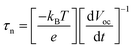 | (2) |
where
kBT is the thermal energy,
e is the positive elementary charge, and d
Voc/d
t is the derivative of the open-circuit voltage transient.
Fig. 7B is the plot of the response time obtained by applying
eqn (2) to the data in
Fig. 7A. At the same
Voc value, the response time of the photoelectrodes follows an order of TiO
2/Fe
2O
3/CdS > TiO
2/Fe
2O
3 > TiO
2 NTAs. Based on the above analyses, the TiO
2/Fe
2O
3/CdS NTA photoelectrode exhibits superior recombination characteristics, with the longer lifetimes indicating enhanced separation of the photogenerated charges in the structure.
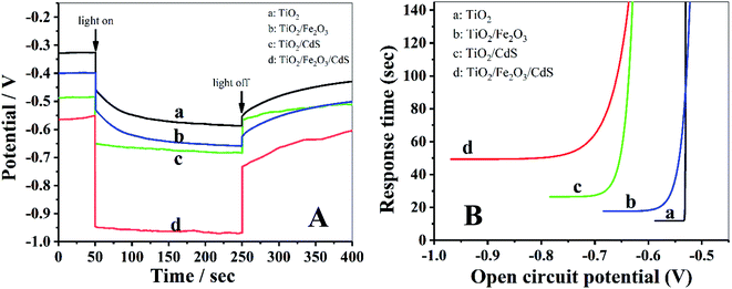 |
| | Fig. 7 (A) The open-circuit photovoltage responses of photoelectrodes. (B) Response time determined by open circuit potential decay for the corresponding photoelectrodes shown in (A). | |
The optical properties of the samples were characterized using the UV-vis diffuse reflectance spectra and PL spectra. Fig. 8A shows that the absorption in the visible range was significantly enhanced with the stepwise modifications of Fe2O3 and CdS nanoparticles (curves b and d). Fig. 8B displays a decrease in PL intensity. The photoluminescence is the result of the recombination of photogenerated electrons and holes.14 Lower photoluminescence intensity represents a lower recombination rate of photogenerated electron–hole pairs, and consequently a longer lifetime of photogenerated carriers, which implies higher photoelectric conversion efficiency.28 The TiO2/Fe2O3/CdS NTAs achieve the highest photoelectric conversion efficiency (Fig. 6B), which is consistent with their highest absorbance in visible light.
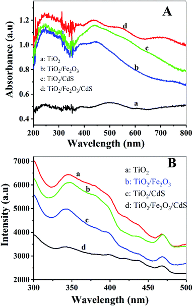 |
| | Fig. 8 (A) Diffuse reflectance absorption spectra of (a) TiO2 NTAs; (b) TiO2/Fe2O3; (c) TiO2/CdS and (d) TiO2/Fe2O3/CdS. (B) PL spectra of these electrodes. | |
3.4. Photocatalytic performance and mechanism of the TiO2/Fe2O3/CdS
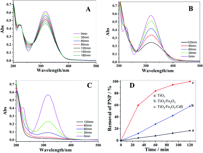
Photocatalytic degradation of PNP solution under visible light was performed to investigate the photocatalytic activities of TiO2 NTAs (Fig. 9A), TiO2/Fe2O3 (Fig. 9B) and TiO2/Fe2O3/CdS (Fig. 9C). The change in PNP concentration during the degradation process was characterized following the Beer–Lambert law by its characteristic absorption at 316 nm. After 120 min of illumination, the photocatalytic degradation of PNP on TiO2/Fe2O3/CdS shows the maximum efficiency; 100% removal is achieved (Fig. 9C), while only 17% and 57.8% removals are achieved on pure TiO2 NTAs and TiO2/Fe2O3 under identical conditions. The removal efficiency is calculated using formula (3):29,30| | |
Removal efficiency = (C0 − C)/C0 × 100%
| (3) |
where C is the PNP concentration obtained after various intervals of time and C0 is the initial concentration. As shown in Fig. 9D, the TiO2/Fe2O3/CdS photoelectrode shows the highest activity. Based on previous reports and the results mentioned above, we hypothesize the following photocatalytic degradation mechanism as illustrated in Fig. 10 with the following equations:30–34| | |
TiO2 → TiO2(h+ + e−); Fe2O3 → Fe2O3(h+ + e−); CdS → CdS(h+ + e−).
| (4) |
| | |
TiO2(h+ + e−) + Fe2O3(h+ + e−) + CdS(h+ + e−) → TiO2 + CdS(htotal+) + Fe2O3(etotal−)
| (5) |
| | |
Fe2O3(etotal−) + O2 → Fe2O3 + ˙O2−
| (6) |
| | |
˙O2H + ˙O2H → H2O2 + O2
| (8) |
| | |
H2O2 + H+ + e− → ˙OH + H2O
| (9) |
| | |
CdS(htotal+) + H2O → CdS + ˙OH + H+
| (10) |
| | |
˙OH + organic pollutants → degradation products
| (11) |
 |
| | Fig. 9 UV-vis spectra of photocatalytic degradation of PNP with different photoelectrodes: (A) TiO2 NTAs; (B) TiO2/Fe2O3; (C) TiO2/Fe2O3/CdS and corresponding photocatalytic performances of these electrodes (D). | |
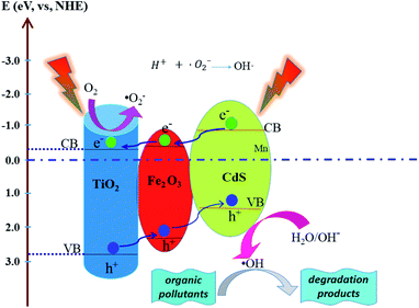 |
| | Fig. 10 Schematic mechanism of the possible photogenerated charge separation and transport in the TiO2/Fe2O3/CdS heterostructure. | |
Electron–hole pairs are produced in the Fe2O3, CdS and TiO2 (eqn (4)) under illumination. The band gap of TiO2 (3.2 eV), CdS (2.4 eV) and Fe2O3 (2.2 eV) reduces progressively with the CB and VB increasing progressively to form a stepwise heterostructure that can absorb visible light. The potentials of the conduction band (CB) and valence band (VB) edges of TiO2, CdS and Fe2O3 were determined using the following formulas:
| | |
EVB = X − E0 + 0.5Eg
| (12) |
where
EVB and
ECB are the VB and CB edge potentials and
X is the electronegativity of the semiconductor; the
X values for TiO
2, Fe
2O
3 and CdS are 5.81 eV, 4.78 eV and 5.18 eV, respectively.
E0 is a constant, about 4.5 eV. According to the formulas, the VB and CB values of CdS are calculated to be 1.45 and −0.89 eV, those of TiO
2 are 2.90 and −0.30 eV, and those of Fe
2O
3 are determined to be 2.54 and −0.35 eV, respectively.
35 Photo-excited electrons in the CB of CdS transfer to Fe
2O
3, and then migrate to TiO
2. On the contrary, the holes in the VB of TiO
2 are transferred to the VB of Fe
2O
3 and CdS stage by stage and eventually accumulate on the surface of CdS (
eqn (5)).
35–39 The separated electrons and the holes are captured by dissolved oxygen molecules and H
2O species respectively to form hydroxyl radicals (˙OH) (
eqn (6)–(10)), a strong oxidizing agent to decompose organic pollutants (
eqn (11)).
24,40
The PL technique was employed to help understand the degradation mechanism.41 TA and ˙OH formed on the photoelectrode surface under UV-vis irradiation readily react to produce a highly fluorescent product, 2-hydroxyterephthalic acid.42 When the TiO2/Fe2O3/CdS serves as the photoelectrode, the PL intensity increases gradually with the increasing irradiation time, indicating that ˙OH was produced indeed during the photocatalytic process (depicted in Fig. 11A). Fig. 11B shows the PL obtained after 20 min of irradiation for different photoelectrodes, and the TiO2/Fe2O3/CdS (curve c) shows the best photocatalytic performance.
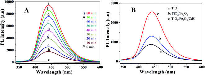 |
| | Fig. 11 (A) PL spectra measured during illumination of TiO2/Fe2O3/CdS and different photoelectrodes (B): (a) TiO2, (b) TiO2/Fe2O3 and (c) TiO2/Fe2O3/CdS. | |
4. Conclusions
A TiO2/Fe2O3/CdS heterostructure was prepared for the first time via annealing amorphous TiO2 NTAs which were pre-loaded with Fe(OH)3 by S-CBD and SILAR processes. The modification of TiO2 NTAs with Fe2O3 and CdS results in a negative shift of the zero-current potential from −0.72, −0.88 to −1.0 V, and a significant increase in photocurrent. The optimal sample demonstrates a solar spectrum photoconversion efficiency of approximately 4.36% and an excellent photocatalytic activity for the removal of PNP. A photodegradation mechanism was proposed on the basis of the matched energy band of TiO2/Fe2O3/CdS favoring the charge transfer and suppressing the photo-induced carrier recombination, leading to the enhanced photocatalytic activity. We believe that it is promising towards the low cost synthesis of high performance photocatalysts for the photodegradation of organic pollutants in aqueous solution.
Conflicts of interest
The authors declare no competing financial interest.
Acknowledgements
This work was financially supported by the National Science Foundation of China (Grant No. 21175038, 21235002 and 21502051), Natural Science Foundation of Hunan Province (2016JJ6101), and Dr Start-up Foundation (Grant No. 15BSQD14). We thank the editor and reviewers for helpful comments and suggestions.
References
- W. Li, J. Yang, Z. Wu, J. Wang, B. Li, S. Feng, Y. Deng, F. Zhang and D. Zhao, J. Am. Chem. Soc., 2012, 134, 11864–11867 CrossRef CAS PubMed.
- G. Cheng, F. Xu, J. Xiong, Y. Wei, F. J. Stadler and R. Chen, Adv. Powder Technol., 2017, 28, 665–670 CrossRef CAS.
- X. Lv, J. Deng and X. Sun, Appl. Surf. Sci., 2016, 369, 314–319 CrossRef CAS.
- X. Yin, P. Sheng, F. Zhong, V. Nguyen, Q. Cai and C. Grimes, New J. Chem., 2016, 40, 6675–6685 RSC.
- S. Kuang, L. Yang, S. Luo and Q. Cai, Appl. Surf. Sci., 2009, 255, 7385–7388 CrossRef CAS.
- H. B. Yang, J. Miao, S.-F. Hung, F. Huo, H. M. Chen and B. Liu, ACS Nano, 2014, 8, 10403–10413 CrossRef CAS PubMed.
- H. Yao, L. Liu, W. Fu, H. Yang and Y. Shi, FlatChem, 2017, 3, 1–7 CrossRef CAS.
- S. J. A. Moniz, S. A. Shevlin, X. An, Z.-X. Guo and J. Tang, Chem–Eur. J., 2014, 20, 15571–15579 CrossRef CAS PubMed.
- Y. Xia and L. Yin, Phys. Chem. Chem. Phys., 2013, 15, 18627–18634 RSC.
- Q. Sun, W. Leng, Z. Li and Y. Xu, J. Hazard. Mater., 2012, 229–230, 224–232 CrossRef CAS PubMed.
- X. Cao, S. Luo, C. Liu and J. Chen, Adv. Powder Technol., 2017, 28, 993–999 CrossRef CAS.
- W. Li, P. Sheng, H. Feng, X. Yin, X. Zhu, X. Yang and Q. Cai, ACS Appl. Mater. Interfaces, 2014, 6, 12353–12362 CrossRef CAS PubMed.
- H. Feng, W. Zhou, X. Zhang, S. Zhang, B. Liu and D. Zhen, Adv. Compos. Lett., 2019, 28, 1–10 Search PubMed.
- L. Wang, W. Gu, P. Sheng, Z. Zhang, B. Zhang and Q. Cai, Sens. Actuators, B, 2019, 281, 1088–1096 CrossRef CAS.
- M. Altomare, N. T. Nguyen, S. Hejazi and P. Schmuki, Adv. Funct. Mater., 2018, 28, 1704259 CrossRef.
- L. Cheng, Q. Xiang, Y. Liao and H. Zhang, Energy Environ. Sci., 2018, 11, 1362–1391 RSC.
- X. Ning and G. Lu, Nanoscale, 2020, 12, 1213–1223 RSC.
- S. G. Kumar, R. Kavitha and P. M. Nithya, J. Environ. Chem. Eng., 2020, 8, 104313 CrossRef CAS.
- R. Yin, M. Liu, R. Tang and L. Yin, Nanoscale Res. Lett., 2017, 12, 520 CrossRef PubMed.
- G. Larramona, C. Choné, A. Jacob, D. Sakakura, B. Delatouche, D. Péré, X. Cieren, M. Nagino and R. Bayón, Chem. Mater., 2006, 18, 1688–1696 CrossRef CAS.
- H. Feng, S. Zhang, X. Zhang, B. Liu and N. Tang, Anal. Methods, 2018, 10, 3462–3469 RSC.
- F. Sastre, A. V. Puga, L. Liu, A. Corma and H. García, J. Am. Chem. Soc., 2014, 136, 6798–6801 CrossRef CAS PubMed.
- S. Khanchandani, S. Kundu, A. Patra and A. K. Ganguli, J. Phys. Chem. C, 2012, 116, 23653–23662 CrossRef CAS.
- Z. Wu, X. Tong, P. Sheng, W. Li, X. Yin, J. Zou and Q. Cai, Appl. Surf. Sci., 2015, 351, 309–315 CrossRef CAS.
- J. Fu, Y. Tian, B. Chang, F. Xi and X. Dong, J. Mater. Chem., 2012, 22, 21159–21166 RSC.
- H. Feng, N. Tang, S. Zhang, B. Liu and Q. Cai, J. Colloid Interface Sci., 2017, 486, 58–66 CrossRef CAS PubMed.
- H. Feng, T. Tran T., L. Chen, L. Yuan and Q. Cai, Chem. Eng. J., 2013, 215–216, 591–599 CrossRef CAS.
- Q. Kang, Q. Z. Lu, S. H. Liu, L. X. Yang, L. F. Wen, S. L. Luo and Q. Y. Cai, Biomaterials, 2010, 31, 3317–3326 CrossRef CAS PubMed.
- H. Zhang, L. Zhao, F. Geng, L.-H. Guo, B. Wan and Y. Yang, Appl. Catal., B, 2016, 180, 656–662 CrossRef CAS.
- W. Li, L. Yao, Z. Zhang, H. Geng, C. Li, Y. Yu, P. Sheng and S. Li, Mater. Sci. Semicond. Process., 2019, 99, 106–113 CrossRef CAS.
- D. Liu, Z. Zheng, C. Wang, Y. Yin, S. Liu, B. Yang and Z. Jiang, J. Phys. Chem. C, 2013, 117, 26529–26537 CrossRef CAS.
- M. A. Mahadik, P. S. Shinde, M. Cho and J. S. Jang, J. Mater. Chem. A, 2015, 3, 23597–23606 RSC.
- X.-F. Gao, H.-B. Li, W.-T. Sun, Q. Chen, F.-Q. Tang and L.-M. Peng, J. Phys. Chem. C, 2009, 113, 7531–7535 CrossRef CAS.
- H. Zhang, X. Quan, S. Chen, H. Yu and N. Ma, Chem. Mater., 2009, 21, 3090–3095 CrossRef CAS.
- R. Lei, H. Ni, R. Chen, H. Gu, B. Zhang and W. Zhan, J. Colloid Interface Sci., 2018, 514, 496–506 CrossRef CAS PubMed.
- M. Tong, D. Sun, R. Zhang, H. Liu and R. Chen, J. Alloys Compd., 2021, 862, 158271 CrossRef CAS.
- S. Zhang, W. Xu, M. Zeng, J. Li, J. Xu and X. Wang, Dalton Trans., 2013, 42, 13417–13424 RSC.
- P. Kuang, L. Zhang, B. Cheng and J. Yu, Appl. Catal., B, 2017, 218, 570–580 CrossRef CAS.
- Y.-S. Lee, C. V. V. M. Gopi, A. Eswar Reddy, C. Nagaraju and H.-J. Kim, New J. Chem., 2017, 41, 1914–1917 RSC.
- C.-C. Hu, T.-C. Hsu and S.-Y. Lu, Appl. Surf. Sci., 2013, 280, 171–178 CrossRef CAS.
- J. Yu, W. Wang, B. Cheng and B.-L. Su, J. Phys. Chem. C, 2009, 113, 6743–6750 CrossRef CAS.
- Q. Xiao, Z. Si, J. Zhang, C. Xiao and X. Tan, J. Hazard. Mater., 2008, 150, 62–67 CrossRef CAS PubMed.
|
| This journal is © The Royal Society of Chemistry 2021 |
Click here to see how this site uses Cookies. View our privacy policy here. 
 Open Access Article
 This Open Access Article is licensed under a Creative Commons Attribution-Non Commercial 3.0 Unported Licence
 *a,
Siqi Fengb,
Niu Tangc,
Songbai Zhangd,
Xiangyang Zhangd and
Bo Liud
*a,
Siqi Fengb,
Niu Tangc,
Songbai Zhangd,
Xiangyang Zhangd and
Bo Liud