DOI:
10.1039/D1RA00031D
(Paper)
RSC Adv., 2021,
11, 9395-9402
Fe2O3 enhanced high-temperature arsenic resistance of CeO2–La2O3/TiO2 catalyst for selective catalytic reduction of NOx with NH3
Received
3rd January 2021
, Accepted 8th February 2021
First published on 2nd March 2021
Abstract
High-temperature arsenic resistance catalysts of CeLa0.5Fex/Ti (x = 0, 0.1, 0.2, 0.3, 0.4, 0.5) series were prepared and measured under a simulation condition of arsenic poisoning. The as-prepared catalysts were characterized by XRD, SEM, TEM, and XPS. The specific surface area and pore size of the catalysts were measured. At x = 0.2, the catalyst shows the best arsenic resistance and catalytic performance. The active temperature range of the CeLa0.5Fe0.2/Ti catalyst is 345–520 °C when the gas hourly space velocity is up to 225![[thin space (1/6-em)]](https://www.rsc.org/images/entities/char_2009.gif) 000 mL g−1 h−1. Compared with commercial vanadium-based catalysts, CeLa0.5Fe0.2/Ti shows much better catalytic performance. The introduction of Fe will improve the dispersion of CeO2 and increase the concentration of Ce3+ and unsaturated active oxygen on the surface. The NH3-TPD and H2-TPR results show that the CeLa0.5Fe0.2/Ti catalyst has more acidic sites and more excellent redox performance than CeLa0.5Fe0/Ti. The CeLa0.5Fe0.2/Ti catalyst might have application prospects in the field of selective catalytic reduction of NOx with NH3.
000 mL g−1 h−1. Compared with commercial vanadium-based catalysts, CeLa0.5Fe0.2/Ti shows much better catalytic performance. The introduction of Fe will improve the dispersion of CeO2 and increase the concentration of Ce3+ and unsaturated active oxygen on the surface. The NH3-TPD and H2-TPR results show that the CeLa0.5Fe0.2/Ti catalyst has more acidic sites and more excellent redox performance than CeLa0.5Fe0/Ti. The CeLa0.5Fe0.2/Ti catalyst might have application prospects in the field of selective catalytic reduction of NOx with NH3.
1. Introduction
Nitrogen oxides (NOx) are some of the main pollutants in the atmosphere, which can do great harm to the ecological environment and human health, such as, acid rain, photochemical smog, ozone depletion, etc.1 Selective catalytic reduction (SCR) of NOx with ammonia is the most effective method to reduce NOx in flue gas of stationary sources. Currently, the most widely used commercial SCR catalyst is V2O5–WO3(MoO3)/TiO2.2,3 The vanadium-based catalyst has many advantages as well as some unavoidable problems, such as, strong biological toxicity of vanadium, narrow temperature window (300–400 °C), easy oxidation of SO2 to SO3, and low N2 selectivity at high temperature.4 Recent reports have shown that CeO2 is the most powerful substitute for V2O5 because of its non-toxicity, high reactivity, and excellent oxygen storage and release capabilities.5–7 However, the adaptability and anti-inactivation ability of CeO2 in a complicated flue gas environment is still an urgent problem to be solved. Heavy metal arsenic, often existing in the form of volatile As2O3 or As2O5 in high-temperature flue gas, is toxic to commercial SCR catalysts.8 Early reports show that the arsenic poisoning of commercial catalysts is due to the coverage of the active sites on the surface of the catalyst by inactive As2O5 and the diffusion of arsenic oxides into the pores of the catalyst, which causes the blocking of the micropores in the catalysts.9–11 The current widely accepted view is that chemical deactivation is the main reason, because arsenic of high oxidation state, As(V), can interact with the active site of vanadium to reduce the surface acid sites.12–14 In order to improve the arsenic resistance, commercial vanadium-based catalysts often need many additives, such as WO3 and MoO3. It has been found that MoO3 has better resistance to arsenic poisoning than WO3 because MoO3 can further improve the dispersion of active sites of vanadium.15 Current literature on arsenic resistance mainly focuses on adding MoO3 to commercial vanadium-based catalysts. However the highest NO conversion of these catalysts after arsenic poisoning is less than 80%.16,17 It is also effective in improving the arsenic resistance of CeO2-based catalysts by adding WO3/MoO3.18–20 However the reported highest NO conversion of the CeO2-based catalysts after arsenic poisoning is only 75%. So far, there is no report on the CeO2-based catalyst by adding Fe2O3 as arsenic resistance catalyst. Recently, our research group has developed the CeO2–La2O3/TiO2 vanadium-free catalysts, which can be used at high temperature and are expected to replace commercial vanadium-based catalysts. Owing to its catalytic activity, sulfur resistance and porous properties, TiO2 is an excellent catalytic carrier. La2O3 is a good auxiliary component for active component of CeO2 because of the formation of Ce–O–La bond on the surface of CeO2, which increases the acidic sites of the catalyst and the adsorption of NH3 and NO. Because Fe-based catalysts have good deNOx performance21,22 as well as good adsorption of arsenic owing to the formation of strong Fe–O–As chemical bond in the removal of the arsenic in the water treatment,23–26 it is expected that Fe2O3 can be used as an arsenic resistance catalyst. In this paper, the Ce–La–Fe–Ti catalysts were obtained by an impregnation method, using anatase as the carrier and Ce–La–Fe oxides as the active component. The deNOx activity of the as-prepared catalysts was measured. The as-prepared catalysts were characterized by XRD, SEM, TEM, and XPS. The reason for the arsenic resistance was discussed.
2. Experimental
2.1 Reagents and preparation
The Ce–La–Fe–Ti composite catalysts were prepared by an impregnation method. First, a certain volume of deionized water was added to a stainless steel reactor and heated to 60 °C. Then ammonia (25–28 wt%) and citric acid (analytical purity) were added to adjust the pH to 3–4 with stirring. After that, anatase pigment (TiO2, industrial grade), Ce(NO3)3·6H2O (industrial grade), La(NO3)3·6H2O (industrial grade), and (NH4)2Fe(SO4)2·6H2O (analytical purity) were added according to the different weight ratios, CeLa0.5Fex/Ti (x = 0, 0.1, 0.2, 0.3, 0.4, 0.5), where 0.5 and x are the weight ratios of La (calculated as La2O3) and Fe (calculated as Fe2O3) to Ce (calculated as CeO2). In all the Ce–La–Fe–Ti composite catalysts, the weight ratio of Ce–La–Fe to Ti (calculated as TiO2) is 3![[thin space (1/6-em)]](https://www.rsc.org/images/entities/char_2009.gif) :
:![[thin space (1/6-em)]](https://www.rsc.org/images/entities/char_2009.gif) 7. The suspension was stirred continuously for 2–3 h and evaporated by vacuum distillation for 1 h. Then the mixture was cooled to room temperature, ripen for 2 hours, dried at 105 °C for 12 h, and calcined at 500 °C in a muffle furnace for 5 h. Finally, the samples were used for the SCR activity test. For comparison, commercial vanadium-based catalysts obtained from the market were also used.
7. The suspension was stirred continuously for 2–3 h and evaporated by vacuum distillation for 1 h. Then the mixture was cooled to room temperature, ripen for 2 hours, dried at 105 °C for 12 h, and calcined at 500 °C in a muffle furnace for 5 h. Finally, the samples were used for the SCR activity test. For comparison, commercial vanadium-based catalysts obtained from the market were also used.
2.2 Catalyst activity tests
First, 1 g as-prepared catalysts were ground in a planetary ball mill for 90 min and soaked in 25 mL 1 mg mL−1 arsenic standard solution (calculated as As2O3) for 3 h to simulate its arsenic poisoning. The water solvent was completely evaporated, thus the loading amount of As2O3 on the catalyst was calculated to be about 2.5 wt%. Then the catalyst was adhered to an industrial honeycomb-shaped cordierite cylinder with size of φ20 × L50. After drying at 105 °C, the loaded cylinder was calcined in a closed tube furnace at 450 °C for 3 h. Then the loaded cylinder was put into a quartz tube furnace to test the activity of the catalyst. The loading amount of the catalyst is 0.8 g. The gas composition is 500 ppm NO, 500 ppm NH3, 300 ppm SO2, 3% O2, 5% H2O, and N2 is used as the balance gas. The total gas flow is 3000 mL min−1, hence the corresponding gas hourly space velocity (GHSV) is calculated to be 225![[thin space (1/6-em)]](https://www.rsc.org/images/entities/char_2009.gif) 000 mL g−1 h−1. The outlet gas concentrations of NO, NO2, SO2 were detected by the Germany Ecom flue gas analyzer and the N2O concentration was detected by the KRM50 infrared flue gas analyzer. The temperature program was controlled by a computer. At each temperature, the experiment was kept for 30 min to stabilize before the data collection of the concentration of the outlet gas. The NO conversion and N2 selectivity were calculated according to the formula (1) and (2).27,28
000 mL g−1 h−1. The outlet gas concentrations of NO, NO2, SO2 were detected by the Germany Ecom flue gas analyzer and the N2O concentration was detected by the KRM50 infrared flue gas analyzer. The temperature program was controlled by a computer. At each temperature, the experiment was kept for 30 min to stabilize before the data collection of the concentration of the outlet gas. The NO conversion and N2 selectivity were calculated according to the formula (1) and (2).27,28| |
 | (1) |
| |
 | (2) |
2.3 Characterization
The Brunauer–Emmet–Teller (BET) specific surface area and pore volume of the samples were measured on the Micromeritics ASAP 2020 instrument. The morphology was observed on the Zeiss MERLIN compact field emission scanning electron microscope (FE-SEM) and a JEOL JEM 2100 plus transmission electron microscope (TEM). The X-ray diffraction (XRD) was performed on the Rigaku Ultima IV instrument, with a tube voltage of 40 kV, a tube current of 40 mA, and Cu Kα radiation. X-ray photoelectron spectroscopy (XPS) was performed on the Thermo ESCALAB 250XI electronic energy spectrometer, with C1s binding energy (284.8 eV) for energy calibration, X-ray source voltage of 16 kV, current of 14.9 mA, beam diameter of 650 μm. The temperature programmed chemical adsorption/reduction (TPD/TPR) was performed on the AutoChem1 II 2920 instrument. For NH3-TPD, the catalyst was pre-treated under argon atmosphere at 350 °C for 1 h, then cooled down to 50 °C and adsorbed NH3 to saturation. After that the temperature was raised to 100 °C and the catalyst was purged with Ar gas to desorb the physically adsorbed NH3. Finally the temperature was raised to 500 °C at a ramping rate of 10 °C min−1 and the outlet NH3 concentration was detected by the thermal conductivity detector (TCD). For H2-TPR, the catalyst was pre-treated under Ar atmosphere at 350 °C for 1 h to remove the adsorbed gas on the surface, then cooled to room temperature. Then the catalyst was reduced in 10% H2/Ar atmosphere from room temperature to 800 °C at a ramping rate of 10 °C min−1. The H2 consumption was detected by TCD.
3. Results and discussion
3.1 Catalytic performance
Fig. 1 shows the catalytic performance of catalysts with different components, in which all the catalysts were treated by arsenic as described in Section 2.2 except “Fresh” catalysts. It can be seen from Fig. 1(a) that the loading of Fe2O3 greatly improves the NO conversion. As temperature increases, the NO conversion first increases and then decreases. Influenced by the kinetics reason, the NO conversion will increase whereas the increasing trend will decrease with the increase of the temperature. If the temperature is too high (>450 °C for CeLa0.5Fe0.2/Ti), the NO conversion will decrease due to the decrease of the N2 selectivity. At the same temperature, the NO conversion first increases and then decreases with the increase of the Fe content. When the Fe2O3 content x is 0.2, the NO conversion of CeLa0.5Fex/Ti is the highest. The temperature range where the corresponding NO conversion is greater than 80% of CeLa0.5Fe0.2/Ti is 345–520 °C. Commercial vanadium-based catalyst shows much weaker arsenic resistance than CeLa0.5Fe0.2/Ti. On the one hand, Fe-based catalysts have good deNOx performance,4,5 on the other hand, Fe might form the bond of Fe–O–As6–9 with As, which makes Fe preferentially combine with As to protect the main active site of CeO2. However, excessive loading of Fe2O3 is detrimental to the deNOx performance of the catalyst, which can be attributed to the fact that excessive Fe2O3 will cover the active sites of the CeO2 on the catalyst surface. Above 350 °C, the NO conversion of the catalyst is maintained at a high level, which may be related to the enhanced oxidation of CeO2.29 The introduction of La increases the surface unsaturated oxygen on the surface and the dispersibility of CeO2.30,31 From Fig. 1(b), it can be found that the commercial vanadium-based catalyst is significantly poisoned in arsenic environment, while CeLa0.5Fe0.2/Ti catalyst is slightly affected in arsenic environment. The NO conversion of the CeLa0.5Fe0.2/Ti is obviously better than commercial vanadium-based catalyst with regard to the arsenic resistance. In Fig. 1(c), the N2 selectivity of the CeLa0.5Fex/Ti (x = 0, 0.1, 0.2, 0.3, 0.4, 0.5) catalysts is much better than that of commercial vanadium-based catalyst and CeLa0.5Fe0.2/Ti shows the best N2 selectivity (99.08–100%). In Fig. 1(d), the N2O concentration of vanadium-based catalysts increases quickly whereas the N2O concentrations of CeLa0.5Fex/Ti (x = 0, 0.1, 0.2, 0.3, 0.4, 0.5) increase slowly. This arsenic poisoning of vanadium-based catalysts is consistent with the results reported in the literature.4
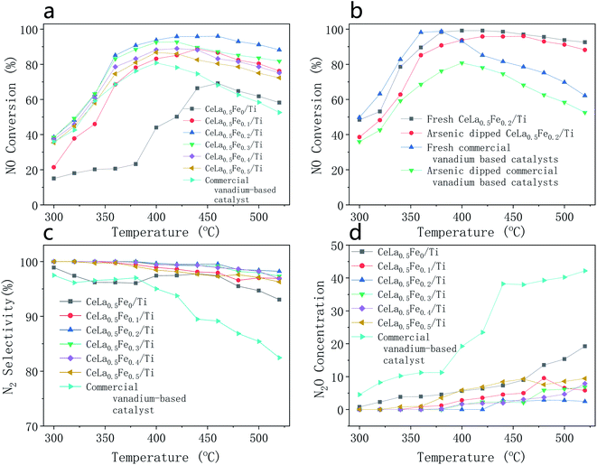 |
| | Fig. 1 Catalytic performance of catalysts with different components, all the catalysts were treated by arsenic as described in Section 2.2 except “Fresh” catalysts. (a) NO conversion of CeLa0.5Fex/Ti (x = 0, 0.1, 0.2, 0.3, 0.4, 0.5) and commercial vanadium-based catalysts; (b) NO conversion of CeLa0.5Fe0.2/Ti and commercial vanadium-based catalyst with and without arsenic solution dipping; (c) N2 selectivity of CeLa0.5Fex/Ti (x = 0, 0.1, 0.2, 0.3, 0.4, 0.5) and commercial vanadium-based catalyst; (d) N2O concentration of CeLa0.5Fex/Ti (x = 0, 0.1, 0.2, 0.3, 0.4, 0.5) and commercial vanadium-based catalyst. | |
3.2 XRD
Fig. 2 shows the XRD pattern of CeLa0.5Fex/Ti (x = 0, 0.1, 0.2) series. The main phase of the three catalysts is anatase TiO2 (JCPDS no. 99-0008). The broad diffraction peaks indicate that the anatase is a nano-particle, which is consistent with the following SEM and TEM results. There are weaker cubic fluorite CeO2 peaks (JCPDS no. 43-1002) near 28.6°, 33°, etc. The full width at half maximum (FWHM) of CeO2 is wider than that of anatase, showing that the grain size of CeO2 is much smaller than that of TiO2. However, there is no phase related to the La2O3, indicating that La2O3 is highly dispersed on the catalyst surface in an amorphous state, which is similar to the literature.32 The XRD peak of Fe2O3 (∼33.15°, JCPDS no. 33-0664) is very weak and very wide, which indicates the Fe2O3 is amorphous. The FWHM of the (111) peak of the CeO2 at 28.5° becomes wider with the increase of the Fe content, which means the addition of Fe decreases the CeO2 grain size. Since CeO2 is the main catalyst, small crystal size is beneficial to increase its catalytic activity. In addition, the peak of CeO2 at 28.5° (after Gaussian fitting) moves towards higher angle direction, which might be caused by the formation of the solid solution of CeO2–Fe2O3. This is because the radius of Ce4+ (eight-coordinated, 0.97 Å) is larger than that of Fe3+ (eight-coordinated, 0.78 Å). It is worth noting that although there are reports in the literature that anatase will transform into rutile at ∼500 °C,33 the rutile phase cannot be found in the catalysts, showing that the catalysts have good thermal stability.
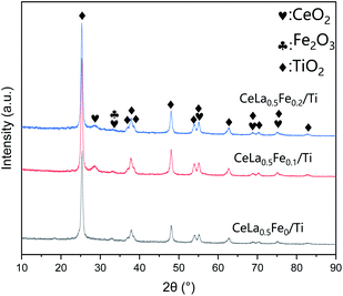 |
| | Fig. 2 XRD pattern of CeLa0.5Fex/Ti (x = 0, 0.1, 0.2) series. | |
3.3 SEM
Fig. 3 is the SEM images of the CeLa0.5Fex/Ti (x = 0, 0.1, 0.2) series. According to the reports, the catalysts with the size of nano-particles can show high catalytic activity.34 As can be seen, the active components are highly dispersed on the surface of the catalysts and the nano-particles form agglomerates with the size of sub-microns. The number of particles increases with the increase of the Fe content, which means that the addition of Fe may enhance the dispersion of CeO2 on the surface of TiO2. This is consistent with the XRD results.
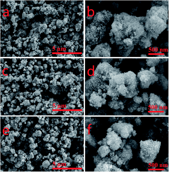 |
| | Fig. 3 SEM images of CeLa0.5Fex/Ti (x = 0, 0.1, 0.2) with different magnification. (a and b) CeLa0.5Fe0/Ti; (c and d) CeLa0.5Fe0.1/Ti; (e and f) CeLa0.5Fe0.2/Ti. | |
3.4 TEM
Fig. 4 shows the TEM image, elemental mapping, and energy dispersive spectra (EDS) of CeLa0.5Fe0.2/Ti. The morphology in Fig. 4(a) clearly shows that the crystal size of the catalyst is tens of nanometers. In the HR-TEM image (Fig. 4(b)), the stripe spacing of 0.357 nm corresponds to the (101) plane of anatase TiO2, and the stripe spacing about 0.318 nm corresponds to the (111) plane of CeO2. The elemental mapping pictures of Ti, Ce, Fe, La, and O (Fig. 4(d–h)) show that the La, Ce, Fe and Ti elements are uniformly distributed in the catalysts. The EDS result in Fig. 4(i) shows that the main elements are Ti, La, Ce, Fe, and Cu, where Cu is caused by the Cu grid used to support the sample.
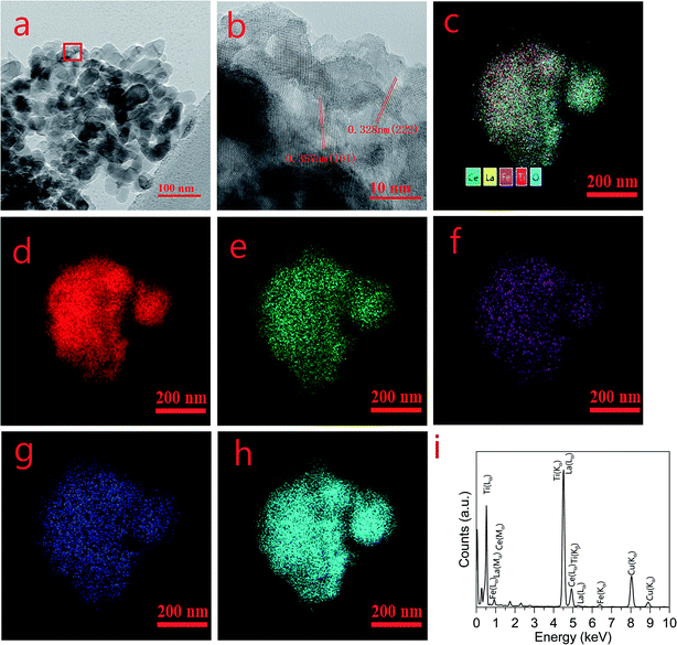 |
| | Fig. 4 TEM images, elemental mapping, and EDS of CeLa0.5Fe0.2/Ti. (a) TEM morphology, (b) HR-TEM, (c) all elements mapping, (d) Ti mapping, (e) Ce mapping, (f) Fe mapping, (g) La mapping, (h) O mapping. (i) EDS. | |
3.5 XPS
Fig. 5 is the XPS spectra of CeLa0.5Fex/Ti (x = 0, 0.1, 0.2). The peaks of Ce, La, Ti, Fe and C can be found in the survey spectra in Fig. 5(a). The Ce3d XPS spectra (Fig. 5(b)) can be fitted to nine peaks, named V1 (≈880.7 eV), V2 (≈882.3 eV), V3 (≈885.8 eV), V4 (≈888.6 eV), V5 (≈898.3 eV), U1 (≈900.8 eV), U2 (≈903 eV), U3 (≈907.3 eV), U4 (≈916.7 eV). All V peaks correspond to Ce3d5/2 spin orbits, and all U peaks correspond to Ce3d3/2 spin orbits. The peaks of V1, V3, and U2 correspond to Ce3+, while the peaks of V2, V4, V5, U1, U3, and U4 correspond to Ce4+.35 From the peak area, the Ce3+ content on the CeO2 surface increases significantly as the Fe content increases. Because of the different electrovalence of Fe3+ and Ce4+, in order to maintain charge balance, the oxygen vacancy defects on the CeO2 surface also increase as the Fe content increases, which are beneficial to the improvement of the catalytic activity.36 The XPS of O1s (Fig. 5(c)) can be fitted into two peaks: Oα (surface unsaturated oxygen, ≈530.6 eV) and Oβ (lattice oxygen, ≈528.7 eV). Calculated by the fitted peak area, the Oα/(Oα + Oβ) fractions of CeLa0.5Fe0Ti, CeLa0.5Fe0.1Ti, CeLa0.5Fe0.2/Ti catalysts are 43.30%, 43.73% and 43.78%, respectively. Because the surface unsaturated oxygen Oα of CeO2 has a higher mobility and a stronger catalytic performance than the lattice oxygen Oβ, CeLa0.5Fe0.2/Ti catalyst shows the best catalytic performance.37 In Fig. 5(d), the peaks of Fe2p correspond to Fe2p1/2 (724 eV), Fe2p3/2 (711 eV) and satellite peaks. The peaks of Fe2p3/2 are fitted by two peaks of Fe2+ (710.0 eV) and Fe3+ (712.8 eV).38 The CeLa0.5Fe0.2/Ti and CeLa0.5Fe0.1/Ti catalysts have no obvious differences in shape and positions, showing that the valances of Fe in the two samples are the same or similar. No obvious satellite peak and asymmetric peak are observed at ∼715 eV, and the peak positions of 2p3/2, satellite, and 2p1/2 are close to that of Fe3+. However the existence of Fe2+ must be considered because Fe2+ can be fitted in the curve. Therefore, it can be concluded that Fe3+ is the major valence while Fe2+ is the minor valence on the surface.39
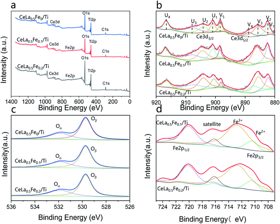 |
| | Fig. 5 XPS spectra of CeLa0.5Fex/Ti (x = 0, 0.1, 0.2). (a) Survey spectra; (b) Ce3d; (c) O1s; (d) Fe2p. | |
3.6 N2 adsorption and desorption
The BET specific surface area, pore volume and pore diameter of CeLa0.5Fex/Ti (x = 0, 0.1, 0.2) series were measured by N2 adsorption and desorption experiments. The results were shown in Table 1. Because the main components of the catalysts are TiO2, CeO2 and La2O3, and the content of Fe2O3 is very little, the change of Fe content has little effect on the specific surface area of the catalyst. The specific surface area increases and the pore size increases slightly. The reason may be that the introduction of Fe inhibits the growth rate of ceria grains and reduces the ceria grain size. This is consistent with the results of the XRD and SEM images.
Table 1 BET specific surface area, pore volume and pore diameter of CeLa0.5Fex/Ti (x = 0, 0.1, 0.2) series
| Catalyst |
SBET (m2 g−1) |
Vp (cm3 g−1) |
Dp (nm) |
| CeLa0.5Fe0/Ti |
78.1 |
0.040 |
3.25 |
| CeLa0.5Fe0.1/Ti |
79.7 |
0.039 |
3.28 |
| CeLa0.5Fe0.2/Ti |
79.9 |
0.041 |
3.32 |
3.7 NH3-TPD and H2-TPR
NH3-TPD result reflects the acidity of the catalysts. Fig. 6(a) shows the NH3-TPD curves of the CeLa0.5Fex/Ti (x = 0, 0.1, 0.2, 0.3) catalysts. As can be seen, the CeLa0.5Fe0/Ti catalyst has two desorption peaks at about 350 °C and 290 °C. It is generally believed that the peak above 450 °C is related to the Lewis acid site (strong acid site) associated with the NH3 molecule, and the peak near 300 °C is related to the Brønsted acid site (weak acid site) associated with NH4+ ions.40 From the peak area, the quantity of the Brønsted acid sites on the surface of the catalyst increases with the increase of Fe content up to x = 0.2, which helps to increase the catalytic activity. This is consistent with the catalytic performance in Fig. 1.
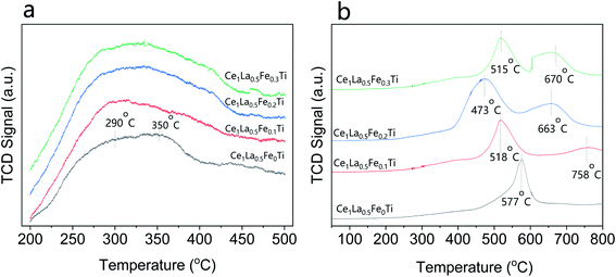 |
| | Fig. 6 (a) NH3-TPD curves of the CeLa0.5Fex/Ti (x = 0, 0.1, 0.2, 0.3) catalysts; (b) H2-TPR curves of the CeLa0.5Fex/Ti (x = 0, 0.1, 0.2, 0.3) catalysts. | |
H2-TPR result reflects the redox characteristics of the catalysts. Fig. 6(b) shows the H2-TPR curves of the CeLa0.5Fex/Ti (x = 0, 0.1, 0.2, 0.3) catalysts. The strong peaks of the four catalysts in the range of 450–580 °C correspond to the reduction process from Ce4+ to Ce3+, which are closely related to the catalytic activity of the catalysts.41 With the increase of Fe content x up to x = 0.2, the peak position shifts towards lower temperature direction from 577 °C to 473 °C, which means that the introduction of Fe makes the reduction of the surface oxygen on CeO2 by H2 more easy. However, when the Fe content increases to x = 0.3, the reduction peak changes from 473 °C to 515 °C, which means that the reduction of CeO2 on the catalyst surface becomes more difficult. From the peak area, the H2 consumption is CeLa0.5Fe0.2/Ti > CeLa0.5Fe0.3/Ti > CeLa0.5Fe0.1/Ti > CeLa0.5Fe0/Ti, showing that the surface oxygen on CeO2 increases with the increase of Fe content, which is consistent with the XPS results. Based on the NH3-TPD and H2-TPR curves, it can be concluded that CeLa0.5Fe0.2/Ti catalyst has the most acidic sites and strongest redox performance.
4. Conclusions
An anti-arsenic SCR denitration catalyst with anatase as the carrier, CeO2, as the main active components, and La2O3, Fe2O3 as the main auxiliary agent was prepared by the impregnation method. The optimized CeLa0.5Fe0.2/Ti catalyst exhibits better catalytic performance under arsenic environment than the commercial vanadium-based catalysts. After the introduction of the Fe2O3, the Ce3+ concentration, surface unsaturated oxygen, CeO2 dispersibility, specific surface area, and acidic sites are all improved, which improves the catalytic activity in the arsenic environment. CeLa0.5Fe0.2/Ti catalyst has high NO conversion efficiency, excellent N2 selectivity and arsenic resistance, which might be a candidate for SCR denitrification applications in the arsenic flue gas environment.
Conflicts of interest
There are no conflicts to declare.
Acknowledgements
The research was supported by the National Natural Science Foundation of China under grant no. 51708447, Key R&D Project of Shaanxi Province under grant no. 2019SF-250, and Major Scientific and Technological Innovation Projects of Shandong Province under grant no. 2019JZZY010343.
References
- S. Luo, W. Zhou, A. Xie, F. Wu and T. Liu, Effect of MnO2 polymorphs structure on the selective catalytic reduction of NOx with NH3 over TiO2-palygorskite, Chem. Eng. J., 2016, 286, 291–299 CrossRef CAS.
- Z. Liu, J. Zhu, S. Zhang, L. Ma and S. I. Woo, Selective catalytic reduction of NOx by NH3 over MoO3-promoted CeO2/TiO2 catalyst, Catal. Commun., 2014, 46, 90–93 CrossRef CAS.
- G. Busca, L. Lietti, G. Ramis and F. Berti, Chemical and mechanistic aspects of the selective catalytic reduction of NOx by ammonia over oxide catalysts: A review, Appl. Catal., B, 1998, 18, 1–36 CrossRef CAS.
- S. Brandenberger, O. Kröcher, A. Tissler and R. Althoff, The state of the art in selective catalytic reduction of NOx by ammonia using metal-exchanged zeolite catalysts, Catal. Rev., 2008, 50, 492–531 CrossRef CAS.
- P. Li, Y. Xin, Q. Li, Z. Wang, Z. Zhang and L. Zheng, Ce–Ti amorphous oxides for selective catalytic reduction of NO with NH3: Confirmation of Ce–O–Ti active sites, Environ. Sci. Technol., 2012, 46, 9600–9605 CrossRef CAS.
- R. Qu, X. Gao, K. Cen and J. Li, Relationship between structure and performance of a novel cerium-niobium binary oxide catalyst for selective catalytic reduction of NO with NH3, Appl. Catal., B, 2013, 142, 290–297 CrossRef.
- H. Li, C. Y. Wu, Y. Li and J. Zhang, Superior activity of MnOx CeO2/TiO2 catalyst for catalytic oxidation of elemental mercury at low flue gas temperatures, Appl. Catal., B, 2012, 111, 381–388 CrossRef.
- C. L. Senior, D. O. Lignell, A. F. Sarofim and A. Mehta, Modeling arsenic partitioning in coal-fired power plants, Combust. Flame, 2006, 147, 209–221 CrossRef CAS.
- E. Hums, Is advanced SCR technology at a standstill? A provocation for the academic community and catalyst manufacturers, Catal. Today, 1998, 42, 25–35 CrossRef CAS.
- Q. Lu, X. Q. Pei, Y. W. Wu, M. X. Xu, D. J. Liu and L. Zhao, Deactivation mechanism of the commercial V2O5–MoO3/TiO2 selective catalytic reduction catalyst by arsenic poisoning in coal-fired power plants, Energy Fuels, 2020, 34, 4865–4873 CrossRef CAS.
- M. Kong, Q. C. Liu, X. Q. Wang, S. Ren, J. Yang, D. Zhao, W. C. Xi and L. Yao, Performance impact and poisoning mechanism of arsenic over commercial V2O5–WO3/TiO2 SCR catalyst, Catal. Commun., 2015, 72, 121–126 CrossRef CAS.
- F. Hilbrig, H. E. Göbel, H. Knözinger, H. Schmelz and B. Lengeler, Interaction of arsenious oxide with DeNox-catalysts: An X-ray absorption and diffuse reflectance infrared spectroscopy study, J. Catal., 1991, 129, 168–176 CrossRef CAS.
- S. Pritchard, S. Kaneko and K. Suyama, Optimizing SCR catalyst design and performance for coal-fired boilers, EPA/EPRI 1995 Joint Symposium Stationary Combustion NOx Control, May 16-19, 1995 Search PubMed.
- I. Morita, M. Hirano and B. H. K. K. Kure, Development and commercial operating experience of SCR DeNOx catalysts for wet bottom coal fired boilers, Power-Gen International, Dec 9–11, 1998 Search PubMed.
- E. Hums, A catalytically highly-active, arsenic oxide resistant V-Mo-O phase — results of studying intermediates of the deactivation process of V2O5 -MoO3 -TiO2 (anatase) DeNOx catalysts, Res. Chem. Intermed., 1993, 19, 419–441 CrossRef CAS.
- Y. Peng, W. Si, X. Li, J. Luo, J. Li, J. Crittenden and J. Hao, Comparison of MoO3 and WO3 on arsenic poisoning V2O5/TiO2 catalyst: DRIFTS and DFT study, Appl. Catal., B, 2016, 181, 692–698 CrossRef CAS.
- Y. Peng, J. Li, W. Si, J. Luo, Q. Dai, X. Luo, X. Liu and J. Hao, Insight into deactivation of commercial SCR catalyst by arsenic: An experiment and DFT study, Environ. Sci. Technol., 2014, 48, 13895–13900 CrossRef CAS.
- X. Li, J. Li, Y. Peng, X. Li, K. Li and J. Hao, Comparison of the structures and mechanism of arsenic deactivation of CeO2–MoO3 and CeO2–WO3 SCR Catalysts, J. Phys. Chem. C, 2016, 120, 18005–18014 CrossRef CAS.
- X. Li, J. Li, Y. Peng, H. Chang, T. Zhang, S. Zhao, W. Si and J. Hao, Mechanism of arsenic poisoning on SCR catalyst of CeW/Ti and its novel efficient regeneration method with hydrogen, Appl. Catal., B, 2016, 184, 246–257 CrossRef CAS.
- X. Li, X. Li, J. Li and J. Hao, Identification of the arsenic resistance on MoO3 doped CeO2/TiO2 catalyst for selective catalytic reduction of NOx with ammonia, J. Hazard. Mater., 2016, 318, 615–622 CrossRef CAS.
- G. H. Yao, K. T. Gui and F. Wang, Low-temperature de-NOx by selective catalytic reduction based on iron-based catalysts, Chem. Eng. Technol., 2010, 33, 1093–1098 CrossRef CAS.
- M. Devadas, O. Kröcher, M. Elsener, A. Wokaun, G. Mitrikas, N. Söger, M. Pfeifer, Y. Demel and L. Mussmann, Characterization and catalytic investigation of Fe-ZSM5 for urea-SCR, Catal. Today, 2007, 119, 137–144 CrossRef CAS.
- Z. C. Li, X. M. Liu, W. Jin, Q. S. Hu and Y. P. Zhao, Adsorption behavior of arsenicals on MIL-101(Fe): The role of arsenic chemical structures, J. Colloid Interface Sci., 2019, 554, 692–704 CrossRef CAS.
- M. A. V. Ramos, W. Yan, X. Li and B. Koel, Simultaneous oxidation and reduction of arsenic by zero-valent iron nanoparticles: understanding the significance of the coreshell structure, J. Phys. Chem. C, 2009, 113, 14591–14594 CrossRef CAS.
- H. P. Feng, L. Tang, J. Tang, G. M. Zeng, H. Dong, Y. C. Deng, L. L. Wang, Y. N. Liu, X. Y. Ren and Y. Y. Zhou, Cu-doped Fe@Fe2O3 core-shell nanoparticle shifted oxygen reduction pathway for high-efficiency arsenic removal in smelting wastewater, Environ. Sci.: Nano, 2018, 5, 1595–1607 RSC.
- M. J. Uddin and Y. K. Jeong, Review: Efficiently performing periodic elements with modern adsorption technologies for arsenic removal, Environ. Sci. Pollut. Res., 2020, 27, 39888–39912 CrossRef CAS.
- Z. Liu, S. Zhang, J. Li and L. Ma, Promoting effect of MoO3 on the NOx reduction by NH3 over CeO2/TiO2 catalyst studied with in situ DRIFTS, Appl. Catal., B, 2014, 144, 90–95 CrossRef CAS.
- W. Shan, F. Liu, H. He, X. Shi and C. Zhang, A superior Ce-W-Ti mixed oxide catalyst for the selective catalytic reduction of NOx with NH3, Appl. Catal., B, 2012, 115–116, 100–106 CrossRef CAS.
- J. W. Shi, Y. Wang, R. B. Duan, C. Gao, B. R. Wang, C. He and C. M. Niu, The synergistic effects between Ce and Cu in CuyCe1−yW5Ox catalysts for enhanced NH3-SCR of NOx and SO2 tolerance, Catal. Sci. Technol., 2019, 9, 718–730 RSC.
- B. Zhang, D. Li and X. Wang, Catalytic performance of La–Ce–O mixed oxide for combustion of methane, Catal. Today, 2010, 158, 348–353 CrossRef CAS.
- Y. Dai, X. Y. Wang, D. Li and Q. G. Dai, Catalytic combustion of chlorobenzene over Mn-Ce-La-O mixed oxide catalysts, J. Hazard. Mater., 2011, 188, 132–139 CrossRef CAS.
- L. Gao, C. Li, P. Lu, J. Zhang, X. Du, S. Li, L. Tang, J. Chen and G. Zeng, Simultaneous removal of Hg0 and NO from simulated flue gas over columnar activated coke granules loaded with La2O3-CeO2 at low temperature, Fuel, 2018, 215, 30–39 CrossRef CAS.
- O. Carp, C. L. Huisman and A. Reller, Photoinduced reactivity of titanium dioxide, Prog. Solid State Chem., 2004, 32, 33–177 CrossRef CAS.
- Z. Yan, J. Wang, R. Zou, L. Liu, Z. Zhang and X. Wang, Hydrothermal synthesis of CeO2 nanoparticles on activated carbon with enhanced desulfurization activity, Energy Fuels, 2012, 26, 5879–5886 CrossRef CAS.
- A. Gupta, M. Hegde, K. Priolkar, U. Waghmare, P. Sarode and S. Emura, Structural investigation of activated lattice oxygen in Ce1-xSnxO2 and Ce1-x-ySnxPdyO2-δ by EXAFS and DFT calculation, Chem. Mater., 2009, 21, 5836–5847 CrossRef CAS.
- T. Montini, M. Melchionna, M. Monai and P. Fornasiero, Fundamentals and catalytic applications of CeO2-based materials, Chem. Rev., 2016, 116, 5987–6041 CrossRef CAS.
- F. Liu, H. He, Y. Ding and C. Zhang, Effect of manganese substitution on the structure and activity of iron titanate catalyst for the selective catalytic reduction of NO with NH3, Appl. Catal., B, 2009, 93, 3760–3769 Search PubMed.
- Z. H. Chen, F. R. Wang, H. Li, Q. Yang and L. F. Wang, Low-temperature selective catalytic reduction of NOx with NH3 over Fe–Mn mixed-oxide catalysts containing Fe3Mn3O8 phase, Ind. Eng. Chem. Res., 2012, 51, 202–212 CrossRef CAS.
- M. T. Van Dongen, D. Ng, L. V. Moura, D. Acharya, J. Wang, C. D. Easton, F. Wang and Z. Xie, Synthesis and characterisation of monolithic PTFE-modified MnOx/FeOx catalysts for selective catalytic reduction (SCR) of NOx at low temperature, J. Chem. Technol. Biotechnol., 2021 DOI:10.1002/jctb.6612.
- R. Zhang, W. Yang, N. Luo, P. Li, Z. Lei and B. Chen, Low-temperature NH3-SCR of NO by lanthanum manganite perovskites: Effect of A-/B-site substitution and TiO2/CeO2 support, Appl. Catal., B, 2014, 146, 94–104 CrossRef CAS.
- Z. Liu, J. Zhu, J. Li, L. Ma and S. I. Woo, Novel Mn-Ce-Ti mixed-oxide catalyst for the selective catalytic reduction of NOx with NH3, ACS Appl. Mater. Interfaces, 2016, 283, 1044–1050 CAS.
|
| This journal is © The Royal Society of Chemistry 2021 |
Click here to see how this site uses Cookies. View our privacy policy here.  Open Access Article
 *a,
Changfei Yea,
Huidong Xie*b,
Chang Yangc,
Jinhong Zhoud and
Chengmin Gee
![[thin space (1/6-em)]](https://www.rsc.org/images/entities/char_2009.gif) 000 mL g−1 h−1. Compared with commercial vanadium-based catalysts, CeLa0.5Fe0.2/Ti shows much better catalytic performance. The introduction of Fe will improve the dispersion of CeO2 and increase the concentration of Ce3+ and unsaturated active oxygen on the surface. The NH3-TPD and H2-TPR results show that the CeLa0.5Fe0.2/Ti catalyst has more acidic sites and more excellent redox performance than CeLa0.5Fe0/Ti. The CeLa0.5Fe0.2/Ti catalyst might have application prospects in the field of selective catalytic reduction of NOx with NH3.
000 mL g−1 h−1. Compared with commercial vanadium-based catalysts, CeLa0.5Fe0.2/Ti shows much better catalytic performance. The introduction of Fe will improve the dispersion of CeO2 and increase the concentration of Ce3+ and unsaturated active oxygen on the surface. The NH3-TPD and H2-TPR results show that the CeLa0.5Fe0.2/Ti catalyst has more acidic sites and more excellent redox performance than CeLa0.5Fe0/Ti. The CeLa0.5Fe0.2/Ti catalyst might have application prospects in the field of selective catalytic reduction of NOx with NH3.![[thin space (1/6-em)]](https://www.rsc.org/images/entities/char_2009.gif) :
:![[thin space (1/6-em)]](https://www.rsc.org/images/entities/char_2009.gif) 7. The suspension was stirred continuously for 2–3 h and evaporated by vacuum distillation for 1 h. Then the mixture was cooled to room temperature, ripen for 2 hours, dried at 105 °C for 12 h, and calcined at 500 °C in a muffle furnace for 5 h. Finally, the samples were used for the SCR activity test. For comparison, commercial vanadium-based catalysts obtained from the market were also used.
7. The suspension was stirred continuously for 2–3 h and evaporated by vacuum distillation for 1 h. Then the mixture was cooled to room temperature, ripen for 2 hours, dried at 105 °C for 12 h, and calcined at 500 °C in a muffle furnace for 5 h. Finally, the samples were used for the SCR activity test. For comparison, commercial vanadium-based catalysts obtained from the market were also used.
![[thin space (1/6-em)]](https://www.rsc.org/images/entities/char_2009.gif) 000 mL g−1 h−1. The outlet gas concentrations of NO, NO2, SO2 were detected by the Germany Ecom flue gas analyzer and the N2O concentration was detected by the KRM50 infrared flue gas analyzer. The temperature program was controlled by a computer. At each temperature, the experiment was kept for 30 min to stabilize before the data collection of the concentration of the outlet gas. The NO conversion and N2 selectivity were calculated according to the formula (1) and (2).27,28
000 mL g−1 h−1. The outlet gas concentrations of NO, NO2, SO2 were detected by the Germany Ecom flue gas analyzer and the N2O concentration was detected by the KRM50 infrared flue gas analyzer. The temperature program was controlled by a computer. At each temperature, the experiment was kept for 30 min to stabilize before the data collection of the concentration of the outlet gas. The NO conversion and N2 selectivity were calculated according to the formula (1) and (2).27,28


