DOI:
10.1039/D0RA10964A
(Review Article)
RSC Adv., 2021,
11, 6985-7014
Immobilization techniques of a photocatalyst into and onto a polymer membrane for photocatalytic activity
Received
31st December 2020
, Accepted 26th January 2021
First published on 10th February 2021
Abstract
This article reviews the various techniques of immobilizing a photocatalyst into and onto the polymer membrane for pollutant removal and as a problem solver in handling suspended photocatalyst issues from the previous literature. A particular focus is given to the preparation of mixed matrix membranes and deposition techniques for photocatalytic degradation in applications for wastewater treatment. Advantages and disadvantages in this application are evaluated. Various operating conditions during the process are presented. About 90 recently published studies (2008–2020) are reviewed. From the literature, it was found that TiO2 is the most favoured photocatalyst that is frequently used in photocatalytic water treatment. Dry–wet co-spinning and sputtering techniques emerged as the promising technique for immobilizing a uniformly distributed photocatalyst within the polymeric membrane, and exhibited excellence pollutant removal. In general, the technical applicability is the key factor in selecting the best photocatalyst immobilizing technique for water treatment. Finally, the scope of various techniques that have been reviewed may provide potential for future photocatalytic study.
1. Introduction
Recently, water pollution and wastewater problems have increasingly become a major concern, especially the leaching of organic pollutants that are not only found in industry and urban areas, but also in all surrounding environments, which can affect the health of mankind.1 Wastewater consists of various pollutants. In particular, the production of chemicals, pharmaceuticals and personal care products (PPCPs) and endocrine disrupting compounds (EDCs) has increased dramatically due to increasing scientific developments.2 Thus, all these chemicals can be considered as the contaminants of emerging concern (CEC). Despite this, the existence of metals and inorganic pollutants (such as nitrate, arsenic, chromium and mercury) in drinking water and wastewater has been given attention due to its environmental problems. Besides, the larger development of industries, especially in food processing, agriculture, and textiles and paper making, involves the excessive use of chemicals, which lead to the higher release of toxic compounds to the environment.3 These species enter water streams through rinsing, washing, processing, dilution, transportation and manufacturing cooling procedures, which lead to the discharge of these chemicals into water bodies, and can give adverse effects not only to human health, but also to the ecosystem.
Various techniques have been proposed for wastewater treatment, such as adsorption, photo-Fenton process,4 biodegradation, ozonation, electrochemical filtration, photocatalytic degradation and membrane technologies. Adsorption offers excellent removal of contaminants in water due to their abundant pore sites and larger surface area to trap pollutants, as well as their low operating cost and ability to reduce the by-product discharge.5 However, the synthesis of powdered adsorbents, such as activated carbon, or agricultural waste (such as date seeds, rice husk, coconut shells and nut shells) requires a higher amount of chemicals during operation,6 have poor selectivity and demonstrate unstable performance.7 Besides, the other technique in wastewater treatment is the Fenton process, which has been successfully implemented in the removal of water pollutants. It involves the use of sulfate radical from the decomposition of persulfate (PS) or peroxydisulfate (PDS) with UV, high temperature and metals.8 Even though this technique offers a low cost method, it limits the oxidizing capability in the degradation of pollutants.
Due to the demands of renewable energy and green environment to save the Earth, photocatalytic treatment using membrane technologies has been widely discussed among various researchers, and has been chosen as an attractive topic in the purification of water and wastewater by using UV or visible light.7 In this photocatalytic theory, the photocatalyst is needed due to the presence of a photogenerated active species that has the capability to activate the degradation process of various organic pollutants under the radiance of light.9 During the degradation process, a hydroxyl radical will be formed from the photoexcitation between light energy with electrons and holes present in the photocatalyst to degrade the pollutant in water. Numerous photocatalysts have been successfully synthesized, such as titanium dioxide (TiO2),10 silver oxide,7 graphitic carbon nitride,11 bismuth oxide,12 and copper oxide.13 Besides, other simple photocatalysts have also been successfully produced, such as phosphorus, boron, sulphur as well as their composites and polymers.14
In the meantime, photocatalytic membrane technology offers a cost-effective alternative as water treatment, which is composed of a flexible way for its usage and shows a powerful capacity of pollutant removal. Thus, it offers sustainable life with safe water. This process only uses a lower amount of energy and easy operation, which helps in saving the environment. In the past few research studies, membrane technologies have revealed its significance in various applications, such as in haemodialysis for blood purification,15 biotechnology, food processing,16 oil–water separation,17 filtration system for drinking water and wastewater treatment. Membranes can be prepared in the form of a polymer structure based on their pore sizes and features.
However, when particles, proteins or colloids are deposited on the surface or in the pores of membrane, it tends to experience membrane fouling, which leads to lower permeation flux and reduces the life span of the membrane. The most unexpected phenomenon is when the fouling is permanent due to the chemisorbance of the foulant on the surface and in the pores of the membrane. According to the researchers, the main cause of the fouling is because the nature of the membrane is hydrophobic. According to Bellardita et al.,9 coupling photocatalysis with a polymeric membrane shows better operation for the photodegradation process, and can minimize the fouling problems. Moreover, an immobilized photocatalyst with a polymeric membrane is better than a suspended photocatalyst to prevent any suspensions left behind in the water after filtration process. Most of the previous reviews only showed a general explanation about the polymeric membrane doped with certain nanoparticles for various wastewater treatments. As stated by Kim and Bruggen,18 the review explains more on the types of nanoparticles used with a polymeric membrane, instead of the immobilization method.
Compared to other previous reviews, this article explains a critical overview on the step-by-step preparation of functionalized photocatalysts incorporated with a polymeric membrane with various techniques that only focuses on the photocatalytic activity. To highlight their technical applicability, various parameters have been discussed, including the specific procedure, structure, pore size and surface area of the immobilized photocatalytic membrane for every technique.
This paper focuses only on the polymeric membrane, instead of the ceramic membrane, because the photocatalyst can be immobilized both into and onto the polymeric membrane. Meanwhile, the photocatalyst can only be deposited onto the surface of the ceramic membrane. This is because the photocatalyst is not recommended for immobilization into the ceramic membrane due to the higher temperature of the sintering process that may demolish the photocatalyst. This review also presents the best methods for immobilizing the photocatalyst into the polymeric membrane (mixed matrix membrane) and for deposition of the photocatalyst onto the polymeric membrane's surface (coating), which may provide a potential outlook for the future photocatalytic technology. The development of the photocatalytic membrane technology may lead to a sustainable environmental purification technology due to the purification without using fossil fuels or harmful chemicals. Not only for water treatment, this technology also can be implemented for wider applications, including air-purification, deodorization, antifouling, antifogging and freshness maintenance.19
2. Photocatalytic membrane
2.1 Photocatalysis
In the fundamentals of chemistry, the catalyst is referred to as a substance that is used to speed up the reaction in a chemical process. Photocatalysis has been known as one of the successful methods in water and wastewater treatment. The photocatalysis method is well known as ‘photoactivated’, and resembles the potentiality of the photocatalyst to perform under the radiance of light based on the active site available at the photocatalyst itself.20 The photocatalyst can be divided into two types, which are the homogenous photocatalyst and heterogeneous photocatalyst, as can be seen in Table 1. According to Baruah et al.,21 homogenous photocatalysis is when the photocatalyst and medium react in the same phase. In contrast, if the photocatalyst and reaction medium are not in the same phase, it can be called heterogeneous photocatalysis. Heterogeneous photocatalysis is better than homogenous photocatalysis due to the easier separation of the used catalyst after application. Moreover, the heterogeneous photocatalyst is more effective in the removal of pollutants because it employs a renewable solar energy that leads to green technology to solve environmental problems.22 For example, a photocatalyst in the solid phase and a reactant pollutant in the liquid phase will be easily adsorbed and degraded in heterogeneous photocatalysis. The significance of the photocatalytic reaction is how it harvests the solar energy to produce more charge carriers, and escalates the exploitation of the charge carriers in the redox reaction.23 In this technology, the ideal photocatalyst is needed to exhibit efficient photocatalytic behaviour, including good photogenerated charge carrier separation, broad light absorption and higher stability, as well as reusability.22 However, the charge carrier recombination ratio, lower reduction potential and photo-corrosion can affect the efficiency of the degradation process.24
Table 1 Difference between the homogenous and heterogeneous photocatalysts
| Homogenous photocatalyst |
Heterogeneous photocatalyst |
| Photocatalyst and medium reacted in same phase |
Photocatalyst and medium reacted in different phase |
| Difficult to separate from solution after reaction |
Easier separation after application |
| Absorb narrowly within solar spectrum |
High activity and non-toxicity |
| Photocatalytic ability and stability are limited |
Stability in aqueous phase |
| Examples: ruthenium and iridium polypyridyl complex |
Examples: semiconductor TiO2, Cu2O, Ag2O, ZnO |
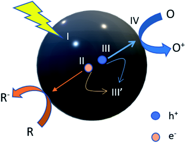
According to the photocatalytic reaction theory, there needs to be photoexcitation that occurs by visible light, UV light or infrared light, depending on the particular energy band gap through the redox reaction. An example of a fundamental theory of how the photocatalytic reaction occurs is revealed in eqn (1.1)–(1.8). When light energy penetrates the photocatalyst, the electrons (e−) in the valence band (VB) will be excited to the conduction band (CB), producing holes (h+) in VB. Thus, e− and h+ will be encountered in the redox reaction.10 During the process, water will dissociate into oxygen (O2) and hydrogen (H+) by photoexcitation of the electron, which leaves the holes. Then, the absorption of energy that is either greater than or equal to its band gap occurs by a semiconductor. There are three stages of water splitting, of which the first stage is the absorbance of energy and e−/h+ generated by photoexcitation. The second stage is the separation of charges at the opposite sides by minimal recombination, and the last stage consists of charge carriers triggering the oxidation and reduction at the VB and CB, respectively. The oxidation of holes towards the hydroxyl ion in water will produce a hydroxyl radical that will then degrade the pollutant, forming CO2 and H2O. The schematic diagram of the basic photocatalysis can be seen in Fig. 1 for further understanding. It indicates how the process of the photocatalyst reacts with light in order to degrade the pollutant, which results in the purification of water.
| | | e−(CB) + h+(VB) → energy | (1.1) |
| | | H2O + h+(VB) → ˙OH + H+ | (1.2) |
| | | ˙OH + pollutant → H2O + CO2 | (1.4) |
| | | ˙OOH + ˙OOH → H2O2 + O2 | (1.6) |
| | | O2˙− + pollutant → CO2 + H2O | (1.7) |
| | | ˙OOH + pollutant → CO2 + H2O | (1.8) |
 |
| | Fig. 1 Steps in the photocatalytic reaction process. R: chemicals in the reductive reaction, O: chemicals in the oxidative reactions. (I) Absorption of light to generate electron–hole pairs; (II) separation of excited charges; (III) holes (h+) and electron (e−) transfer to the photocatalyst surface; (III′) recombination of electrons and holes; (IV) utilization of charges on the surface for redox reactions. | |
The significant characteristics in determining a good photocatalyst that can react under light irradiation are their physical and chemical stability, inexpensiveness, availability, oxidative capability and non-toxic nature.25 The most outstanding photocatalyst that been used in the past literature is titanium dioxide (TiO2), whether in suspended form or immobilized into or onto the membrane. TiO2 has been chosen by most previous research groups as a photocatalyst due to the longer timespan of the electron–hole pairs, stability for a wide range of pH values, higher catalytic activity and known property as a cost-effective material. TiO2 can be confirmed as an effective photocatalyst under irradiation of UV light at wavelengths less than 400 nm due to its larger band gap of TiO2.26 However, TiO2 cannot be used under visible light irradiation due to its wide band gap. To overcome this problem, TiO2 must be doped with another narrow band gap photocatalyst, or the small band gap photocatalyst should be used alone in order to react effectively under visible light. There are photocatalysts with tunable band gaps that can be used, such as ZnO,27 Cu2O,28 Ag,29 Bi2O3,30 carbon nanotubes,31 and others.
Photocatalysis provides a good replacement for energy-saving treatment methods by using renewable and pollution-free solar energy. The process also offers the demolition of a variety of dangerous compounds, which lead to the formation of harmless products. In addition, the reaction condition requires less chemical input and minimal secondary waste generation. Not only for water treatment, photocatalysis can also be applied for the generation of hydrogen, gaseous phase and solid phase treatments.32 Photocatalysis also has challenges in terms of the inhibition of the charge carrier recombination, charge separation and interfacial charge transfer.
2.2 Polymeric membrane
The various materials that have been successfully used in the fabrication of polymeric membranes are polyvinylidene fluoride (PVDF), polysulfone (PSF), polyether sulfone (PES), polyacrylonitrile (PAN), polyvinyl alcohol (PVA) and polyethylene (PE). Table 2 summarizes the various types of polymer membranes with their physical–chemical properties. The polymer membrane is widely used in industry due to its outstanding features, such as low cost, high mechanical strength, stability and flexibility.33 In addition, the polymer membrane is also available in various configurations in order to achieve higher performance of the membrane filtration. These configurations include the flat sheet, spiral, and hollow membrane, which play significant roles in producing the structure and characteristics of efficient membranes. Among these configurations, the flat sheet is the easiest to be fabricated. However, it experiences a lower surface area. Apart from that, the spiral configuration gained interest due to the higher surface area. Unfortunately, it also faces drawbacks, such as its ease of being clogged by particulates. Apart from that, the hollow fibre membrane configuration offers higher mechanical stability, higher surface area and ease in fabrication, as well as suitability for photocatalyst support.6 The polymeric membrane can be formed for microfiltration (MF), ultrafiltration (UF), nanofiltration (NF), and reverse osmosis (RO).34 The pore size of MF is between 0.1–10 μm, while UF is between 0.01–0.1 μm.35 Besides, the pore size of NF is around 1 nm, which is capable of removing small particles, such as dyes.36 Usually, MF is used for the removal of suspended solids, organic colloids, and bacteria, while UF is capable of removing pathogens, viruses and colloids.37 The different characteristics between microfiltration, ultrafiltration and nanofiltration polymeric membranes that have been discussed is summarized in Table 3. There are various methods to fabricate polymer membranes, including electrospinning, sintering, template leaching, stretching, track-etching and phase inversion. Phase inversion is a simple technique, which can be used in fabricating various types of polymers with a variety of membrane configurations. Besides, various diameters and structures of membranes can be fabricated with easy operation by electrospinning. However, it possesses a slow speed yield of membrane. Other methods, namely sintering and stretching, are capable of producing stable microfiltration polymeric membranes with certain types of polymers, namely PE and PTFE. Although this method does not involve a solvent, it needs a higher temperature during the procedure. Besides, the track-etching method shows an advantage because it can produce both microfiltration and ultrafiltration polymeric membranes. However, it also encounters a drawback due to its costly method, which is the same as the template leaching method. Table 4 summarizes the advantages and disadvantages of these methods.
Table 2 Various types of polymer membranes
| Material |
Physical–chemical properties |
References |
| Polyvinylidene fluoride (PVDF) |
High thermal stability |
38
|
| Good chemical resistance |
| Excellent mechanical property |
| Polyacrylonitrile (PAN) |
Withstands corrosive environment |
39
|
| Polyethersulfone (PES) |
Better chemical & thermal stability |
40
|
| Less hydrophobic |
| Polypropylene (PP) |
Hydrophobicity |
41
|
| Good thermal evaporation |
| Better water flux |
| Polytetrafluoroethylene (PTFE) |
Hydrophobic |
22
|
| Narrow pore size |
| Better porosity |
| Excellent mechanical strength |
Table 3 Different characteristics of polymer membranes42
| |
Microfiltration (MF) |
Ultrafiltration (UF) |
Nanofiltration (NF) |
| Thickness of separating layer |
10–150 μm |
0.1–1.0 μm |
0.1–1.0 μm |
| Pore size |
0.1–10 μm |
0.01–0.1 μm |
1–10 nm |
| Molecular separation size |
Solids: >0.1 μm |
Solids: >0.5 μm |
Solids: >0.001 μm |
| Particle separation |
Macromolecule separation |
Low-MW solute separation |
| Operating pressure |
0.1–3 bar |
0.5–10 bar |
2–40 bar |
| Separating mechanism |
Separation based on particle size |
Separation based on difference in solubility and diffusivity |
| Module types |
Spiral-wound, hollow fibre, tube, plate or cushion module |
Spiral-wound, tube or cushion module |
Table 4 The various methods used for fabricating the polymer membrane
| Fabrication methods for membrane |
Advantages |
Disadvantages |
| Phase inversion |
• Increase speed yield |
• Solvent needed |
| • Better porosity |
| • Simple |
| • Flat-sheet and tubular membrane configuration |
| • Broad polymer variety fabrication |
| Electrospinning |
• Better versatility in controlling nanofiber diameter and structure |
• Slow speed yield |
| • Easy operation with additive |
| • Easy process |
| Sintering |
• Solvent not needed |
• Difficult to achieve smaller pores below 100 nm |
| • Produce 0.1–10 micrometre pore size |
• Lower porosity |
| • Chemically stable for polytetrafluoroethylene (PTFE) and polyethylene (PE) |
• High temperature needed |
| Stretching |
• Produces 0.1–3 micrometre pore size |
• High temperature needed |
| • Porosity (60–80%) with ladder-like slit shape |
| • Chemically stable for PTFE and PE |
| Track-etching |
• Produces 0.02–10 micrometre pore size |
• Low porosity |
| • Narrow pore size distribution |
• Expensive |
| • Produces cylindrical pore shape |
• Limited polymer |
| Template leaching |
• Produces 0.1–10 micrometre pore size |
• Difficult to obtain nano pores |
| • High flux |
• High cost |
| • Complex process |
2.3 Photocatalytic membrane
Recently, the photocatalytic membrane has become a promising technology to overcome the drawbacks of photocatalysis in terms of the suspended photocatalyst during the membrane separation process. According to Molinari et al.,43 the suspended photocatalyst shows advantages, such as a higher surface area, which lead to higher photocatalytic efficiency. However, the photocatalyst used in the suspended nanosized photocatalyst encountered drawbacks in the recovery process, and was left behind in water during the filtration process. Therefore, it can cause membrane fouling that reduces the permeate flux, which lowers the photocatalytic activity. Moreover, the recovery of the photocatalyst after the separation process may require high-cost treatment and be more time-consuming.
The photocatalyst comes with different structures, including fine particles, powders, granules and a solid metal target. For a photocatalyst immobilized into the polymer membrane, a powdered photocatalyst is preferred. The powdered photocatalyst can be obtained by purchasing a commercial photocatalyst or by synthesis process, such as co-precipitation and sol–gel method. The commercial or synthesized photocatalyst was dispersed inside the polymer dope solution, and mixed homogenously to prevent agglomeration of the particles. Usually, for the mixed matrix membrane, a mixture of the polymer and photocatalyst was used as the main materials for fabrication. From the structure, it was observed that small particles were distributed inside the polymer matrix. Different from the deposition method, the fabricated polymeric membrane became a substrate or support for photocatalyst landing. For the deposition method, powdered or metal (target) photocatalyst may be used. For example, the polymeric membrane will be used as a substrate to be coated with photocatalyst dope solution by dip coating and electrospraying. For the sputtering method, the metal target will be used as a photocatalyst and deposited on the surface of the polymeric membrane by ejection of metal atoms. Hence, a layer of photocatalyst will be formed on the surface of the polymeric membrane. Furthermore, the photocatalyst only attaches on the surface without entering the polymeric membrane matrix.
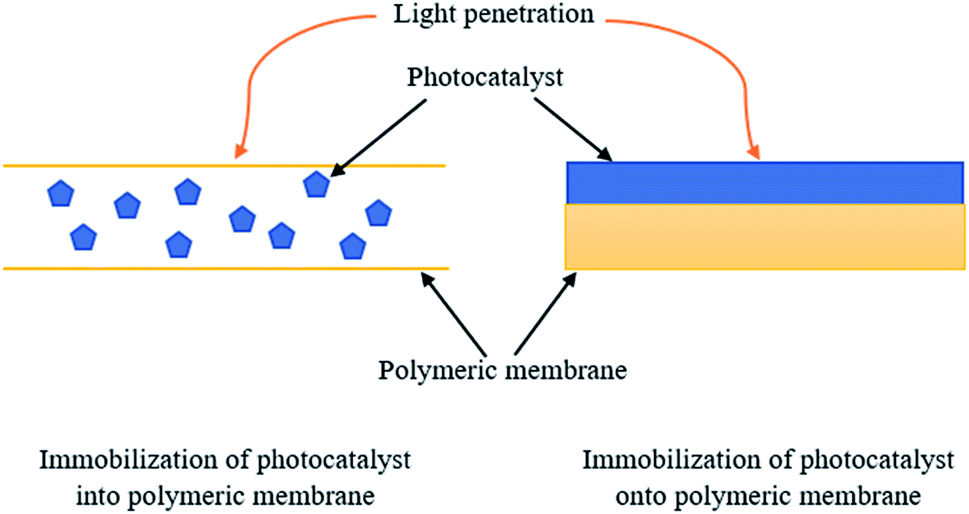
For immobilization of the photocatalyst into the polymeric membrane, light will reach the polymeric membrane first before entering and being absorbed by the photocatalyst. In contrast, for immobilization of the photocatalyst onto the polymeric membrane, light will directly penetrate the photocatalyst layer attached on the surface of the membrane without reaching and entering the membrane. Fig. 2 indicates the illustration of light penetration towards the photocatalyst immobilized into and onto the polymeric membrane.
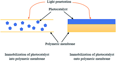 |
| | Fig. 2 Illustration of light penetration towards the photocatalyst immobilized into and onto the polymeric membrane. | |
The chemical and physical nature of the photocatalyst and membrane surfaces act as significant factors in the interaction between the photocatalyst and polymeric membrane.44 It is critical to know how the photocatalyst interacts with the polymeric membrane for the membrane-binding photocatalyst. Based on a previous study in the literature explained by Rasch et al.,45 the interaction between gold (Au) nanoparticles and the cell membrane has been studied. Au nanoparticles were observed to penetrate and embed the hydrophobic region (L-α-phosphatidylcholine). The accumulation and incorporation of nanoparticles at one side of the vesicle occurred due to the energy expended during this process, as can be seen in Fig. 3. Moreover, the larger number of embedded nanoparticles in the bilayer can be explained by considering the strong driving force that contributes to the nanoparticle insertion. The free energy change ΔGsolv to fit the hydrophobic modified Au nanoparticles into the hydrophobic cell membrane from the water phase was found to be πD2γ, where D and γ are the diameter of the nanoparticle and liquid–vapor surface tension of water, respectively. The accumulation of nanoparticles and the cell membrane may create voids around each individual nanoparticle. The voids form clusters by attracting other nanoparticles, and this clustering phenomenon may be known as the interparticle interaction.46 Moreover, it is stated that strong van der Waals forces is the cause of the clustering of the nanoparticle during the heating process. The repulsive force at the gel phase and attractive force at the fluid phase specify that the embedded nanoparticles undergo clustering spontaneously during the heating process, while declustering during the cooling process.
 |
| | Fig. 3 (i) Insertion of the hydrophobic nanoparticle into the lipid bilayer leads to membrane deformation. (ii) Two nanoparticles present in the bilayer, and (iii) aggregation of the nanoparticles. | |
Besides, adsorption or the particles' charge could also be one of the interaction modes between the photocatalyst and polymer membrane. For example, the photocatalyst and membrane must exhibit different charges, so that the electrostatic interaction can take place. Thus, the nanoparticles can embed inside the polymeric membrane or attach onto the membrane surface. According to Chen et al.,47 a positively charged polymer with negatively charged nanoparticle uses electrostatic attraction as the driving force, and tends to increase the rigidity and alter the permeability.
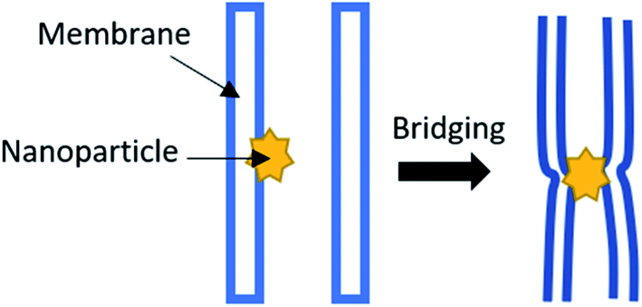
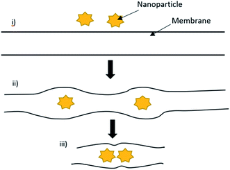
If there is an interaction between the nanoparticles and polymeric membrane, the morphology is strongly decided by the charge and size of the interacting components.48–52 Moreover, the higher loading of the nanoparticles by adsorption or incorporation into the polymeric membrane may be due to their higher stability.49 When the nanoparticles with a size up to 100 nm interact with the polymeric membrane, dissimilar behaviour may be observed. It is stated that hydrophilic nanoparticles are immobilized onto or into the membrane, while hydrophobic nanoparticles can only be immobilized into the membrane with difficulty, as the membrane is destroyed when a higher loading of nanoparticles has been applied.53–55 According to Krack et al.,56 the mass ratio r = mn/mp of the nanoparticles, where mn is the nanoparticle, while mp is the polymer. It needs to be less than the critical ratio r* ≈ 0.2 to 0.3; otherwise, agglomeration of the polymer/nanoparticles will occur. The nanoparticle decoration of the polymeric membrane interface can induce the bridge formation from one bilayer to an adjacent bilayer, resulting in bilayer pairing, as can be seen in Fig. 4 below.57 Furthermore, when the hydrophobic nanoparticles were introduced, it tended to increase the membrane thickness and enhance the mechanical strength.
 |
| | Fig. 4 Nanoparticle decorating the interface of the polymeric membrane, which induces the bridge formation. | |
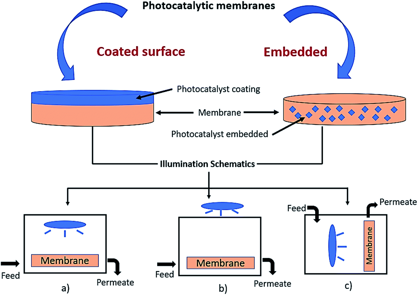
Incorporating the photocatalyst into the polymeric membranes has been widely implemented in previous studies due to their hydrophilicity to minimize fouling, provide strength, as well as increase the permeability.6 Previous research also concluded that by adding particles or a catalyst into the polymer matrix, the polymeric membrane became more stable due to the perm-selectivity and temperature changes. Moreover, by immobilising the photocatalyst onto the support (such as a polymeric membrane), it can prevent the post-separation obstacle correlated with the powdered photocatalyst.58 Therefore, the performance of the photocatalytic technology can be increased as the polymeric membrane becomes the support for the photocatalyst, and also act as a membrane barrier for the removal of pollutants.59 An illustration of the immobilized photocatalyst on the surface coated and embedded membrane with an illustration of the light illumination is shown in Fig. 5. The overview flow chart of the immobilized technique of the photocatalyst with a polymeric membrane in this study is revealed in Fig. 6. There are two techniques of deposition: either into or onto the substrate. Deposition into the membrane is called a mixed matrix membrane, while deposition onto the substrate membrane is referred to as coated membrane. This study will discuss the deposition of the photocatalyst into the polymeric membrane by dry–wet spinning, electrospinning, tape casting and spin coating. Meanwhile, deposition of the photocatalyst onto the surface of the membrane is composed of sputtering, dip coating, electrospraying and atomic layer deposition.
 |
| | Fig. 5 Illustration of the immobilized photocatalyst on the surface and embedded membrane. Illustration of light illumination of the: (a) light source inside the reactor, (b) light source outside the reactor, and (c) vertical light source and membrane inside the reactor. | |
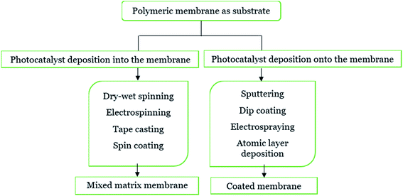 |
| | Fig. 6 Immobilization technique of the photocatalyst into/onto the polymeric membrane. | |
3. Photocatalyst immobilization method
3.1 Deposition into the membrane structure
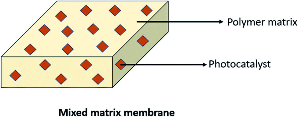
Basically, the polymer was mostly used as a support for the immobilized photocatalyst blended with the membrane or called as a mixed matrix membrane. By blending the photocatalyst into the membrane, it can be one of the efficient techniques in controlling the hydrophilicity of the membrane and prevent fouling.60 This technique can reduce photocatalyst leaching, which contributes to the benefit of this membrane. Moreover, this technique offers advantages, including the low use of energy and better reusability.61 However, some literature found that this technique also encountered a drawback, such as agglomeration of the photocatalyst inside the membrane. To obtain a mixed matrix membrane that blends with the photocatalyst, methods (including wet spinning, sintering and electrospinning) can be done.3 Prepared polymer mixed matrix membranes (MMMs) have been reported in past research studies for dye removal using N-doped polyvinylidene fluoride (PVDF) hollow fibre membranes62 and polysulfone (PSF)/N,Pd co-doped TiO2 composite membranes,63 ibuprofen degradation using a Cu2O/PSF membrane,28 pollutant removal using a polyether sulfone (PES)-fGo mixed matrix membrane,64 ammonium removal using the zeolite-doped PSF membrane,65 2,4-dichlorophenol degradation using the Co/TiO2-PES membrane66 and nonylphenol removal using the TiO2/PVDF dual layer hollow fibre membrane.67 A diagram of the mixed matrix membrane is illustrated in Fig. 7, while the SEM image of the photocatalyst dispersed in the polymeric membrane is shown in Fig. 8.
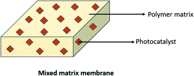 |
| | Fig. 7 Diagram of the ideal mixed matrix membrane. | |
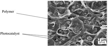 |
| | Fig. 8 SEM image of the photocatalyst dispersed in a polymeric membrane.68 | |
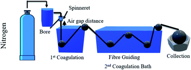
3.1.1 Dry–wet spinning and dry–wet co-spinning technique.
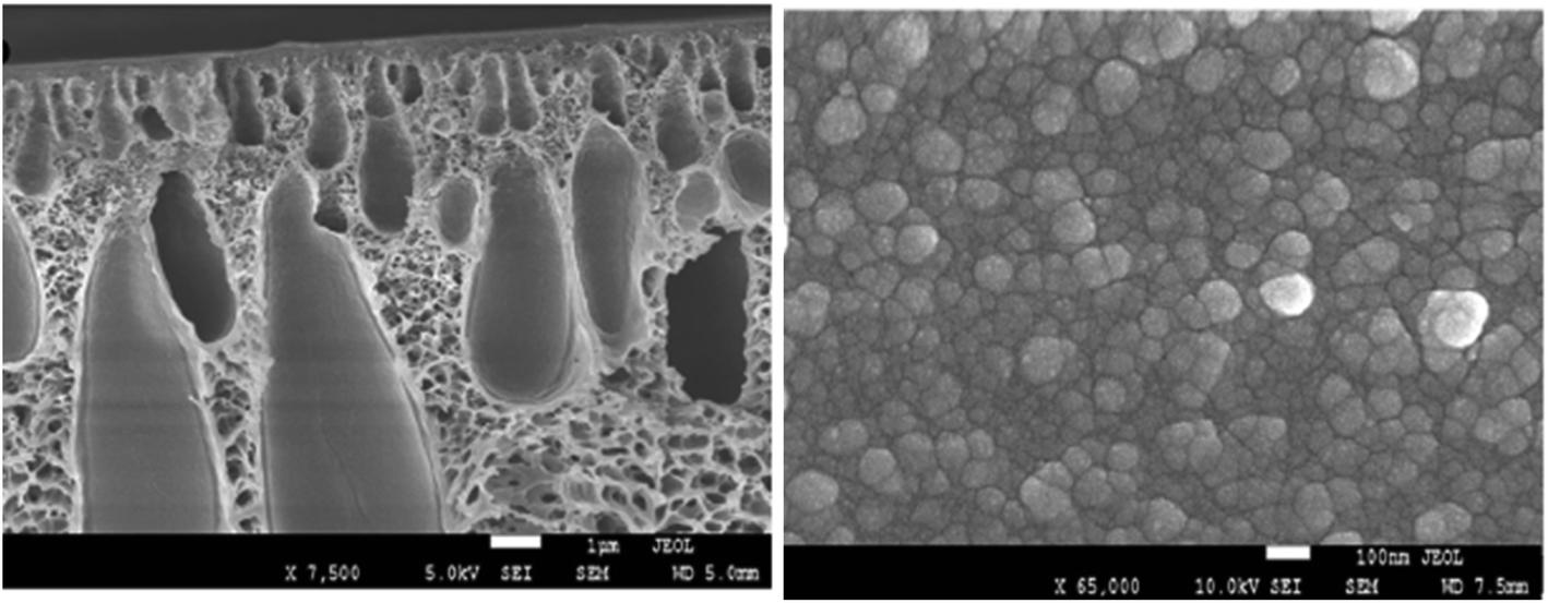
Titanium dioxide (TiO2) is a well-known metal oxide that has widely been used as a photocatalyst in photodegradation due to its outstanding characteristics, including good chemical stability,69 safe to the environment, and low cost. It also has excellent oxidation capability to enhance the pollutant's degradation efficiency.70 The polymeric membrane has gained much interest from the past literature as a landing support for TiO2 that acts as a photocatalytic membrane. The single layer photocatalytic polymeric hollow fibre membrane can be fabricated by dry–wet spinning technique using a single spinneret,71 as shown in Fig. 9, while the dual layer of the membrane can be fabricated by dry–wet co-spinning technique using a triple orifice spinneret, as shown in Fig. 10. In addition, the single layer membrane only needs one dope solution. In contrast, the dual layer membrane needs inner and outer dope solutions. The difference between the single layer and dual layer hollow fibre can be seen in Table 5.
 |
| | Fig. 9 Schematic diagram of the dry–wet spinning system for the single layer hollow fibre membrane. | |
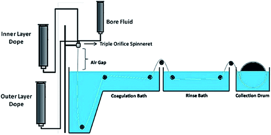 |
| | Fig. 10 Schematic diagram of the dry–wet-co spinning system for the dual layer hollow fibre membrane.62 | |
Table 5 Difference between the single layer and dual layer hollow fibre
| Type |
Single layer |
Dual layer |
| System |
Dry–wet co-spinning |
Dry–wet spinning |
| Spinneret |
Single |
Triple orifice |
| No. of dope |
One |
Two |
| Application |
Degradation |
Outer-degradation |
| Filtration |
Inner-filtration |
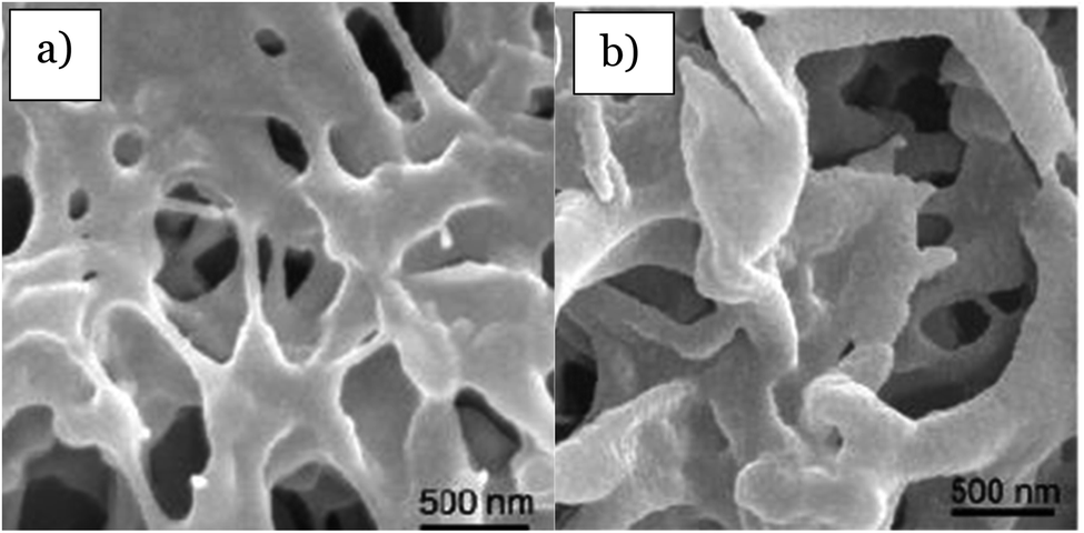
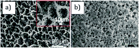
Otitoju et al.72 explained the fabrication of the single layer hollow fibre membrane. A mixture of the photocatalyst, namely CaCu3Ti4O12 (CT), with PVP, PES and DMAc was stirred for 24 hours as the dope solution, which was later used in the spinning system to produce the hollow fibre mixed matrix membrane. 18% of PES and a different percentage of CT were used as the dope composition. During the spinning process, the air gap used was 23.5 cm, distilled water as the bore fluid, 17 rpm for the gear pump, and the external diameter of spinneret was 0.6 mm. SEM images in Fig. 11 show the porous finger-like structure. A white cluster of CT nanoparticles can be seen on the surface of the membrane. The higher the amount of CT powder, the higher the white cluster of CT observed. Table 6 states the pore volume, pore diameter and surface area of the PES-CT membrane evaluated using N2 adsorption–desorption isotherms by BET analyzer. According to this study, the results show the increasing number of pore volume, pore diameter and surface area due to the increasing amount of CT powder. Thus, the photocatalytic activity was enhanced due to the larger surface area and high hydrophilicity. However, it might be different with other studies because the types of nanoparticles used are based on the nanoparticle size and other properties. A larger surface area of the membrane enhances the illumination of UV light, so that it improves the contaminant absorption. Besides, the porous membrane structure makes it easier for the contaminants to be entrapped in the pores. Therefore, there was a great chance for the photogenerated electron hole pairs to react with the contaminants. The photocatalytic mixed matrix membrane successfully degraded 74.83% of Rhodamine B under 360 W UV-C light irradiation.72 However, when the CT powder was 4 wt% in C4, the pore volume, pore diameter and surface area started to decrease due to the higher amount of CT, leading to the aggregation of particles in the pores. According to Naushad et al.,73 the undesirable light scattering or blocking of light may happen when the catalyst concentration used is too high. Moreover, the catalyst may be agglomerated at a higher concentration, which leads to the photocatalyst surfaces not being exposed completely during photocatalysis. Thus, there is a decrease in the degradation efficiency.
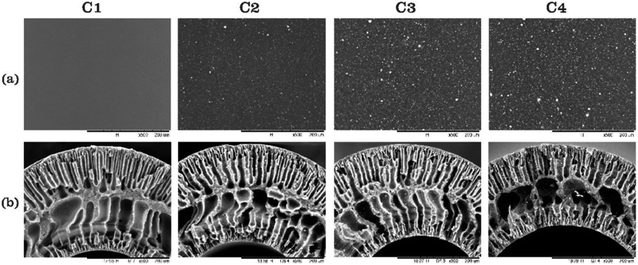 |
| | Fig. 11 SEM images of the (a) surface and (b) cross-section of the PES-CT composite membrane with a composition of CT powder at: (C1) 0 wt%, (C2) 1.25 wt%, (C3) 2.5 wt% and (C4) 4 wt%.72 | |
Table 6 The surface area, pore volume and pore diameter of the pristine and PES-CT composite membrane by BET isotherm72
| Membrane type |
Surface area (m2 g−1) |
Pore volume (cm3 g−1) |
Average pore diameter (nm) |
| C1 |
11.86 |
0.027 |
11.86 |
| C2 |
14.45 |
0.032 |
23.10 |
| C3 |
25.28 |
0.055 |
34.64 |
| C4 |
23.22 |
0.053 |
32.47 |
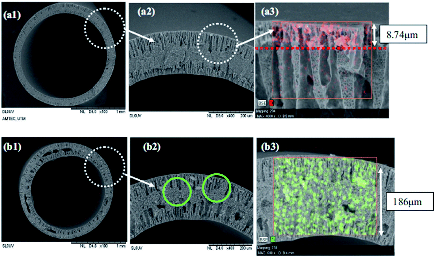
According to Dzinun et al.,67 TiO2 has been chosen as an effective photocatalyst to be deposited onto the single layer and dual layer of the PVDF hollow fibre membrane in the photodegradation of nonylphenol under UV light irradiation. The single layer polymeric membrane was fabricated when 7.5 wt% of TiO2 was mixed with PVDF and DMAc as the inner dope composition. From the SEM image in Fig. 12(b), the single layer hollow fibre membrane displays the agglomeration of TiO2 particles due to the higher loading of TiO2 that leads to less hydrophilic nature. For the dual layer photocatalytic polymeric membrane, a mixture of PVDF and DMAc acts as the inner dope composition, while the outer dope composition consists of TiO2, PVDF and DMAc. The mixture of the inner and outer dope compositions was stirred well using an overhead stirrer until it became homogeneous. This technique can optimize the TiO2 dispersion and reduce the agglomeration problem. According to Dzinun et al.,67 a lower amount of TiO2 particles was distributed well into the outer layer of the dual layer hollow fibre membrane than in the single layer, as shown in Fig. 12. Thus, no TiO2 diffusion into the inner layer was observed from the EDX analysis, as shown in this figure. As mentioned by Dzinun et al.,74 the extensive spread of the TiO2 particles in the membrane matrix provides higher affinity of the metal oxide to water, which lead to more hydrophilicity. With the increase in the addition of TiO2 that was entrapped in the membrane, the performance of the photocatalytic degradation of nonylphenol was around 85% using the dual layer, while 70% was achieved using the single layer under UV-A irradiation. Additionally, the uniform spread of TiO2 inside the polymer membrane led to the complete exposure of TiO2 towards light. This is due to the low amount of catalyst used that can prevent agglomeration, which can reduce the surface area.
 |
| | Fig. 12 The distribution of TiO2 particles in: (a) dual and (b) single layer of the PVDF hollow fibre membrane from SEM images.67 | |
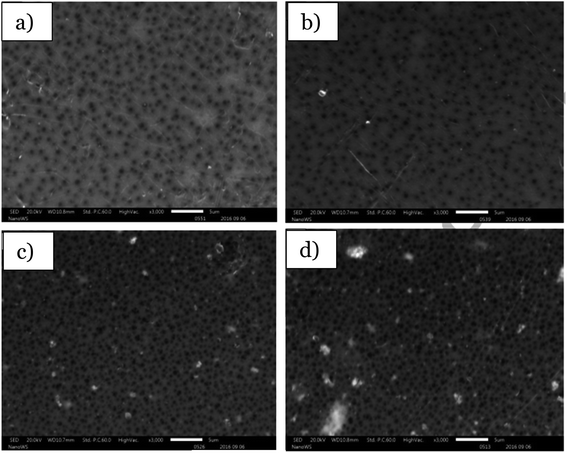
Besides, Kamaludin et al.62 stated in the paper that 75% of the Reactive Black 5 (RB5) dye was successfully degraded after 360 min using the N-doped TiO2-PVDF dual layer hollow fibre membrane, which had a photocatalyst embedded inside the hollow fibre membrane. To produce the fabricated photocatalytic membrane, N-doped TiO2 was mixed with PVDF and PEG 6000 as the outer dope composition, while only PVDF and PEG 6000 were used as the inner dope composition. Both dope compositions were then transferred into the stainless-steel dope reservoir pump to produce the dual hollow fibre membrane. The triple orifice spinneret was used in the spinning system to extrude the dual hollow fibre membrane that acted as the mixed matrix membrane. The SEM images in Fig. 13 shows that the N-doped TiO2 nanoparticles with different weight percentages were evenly distributed on both membrane surfaces. However, when a higher amount of N-doped TiO2 nanoparticles was added to the dope solution, it resulted in a higher amount of nanoparticles distributed in the membranes. Thus, this resulted in agglomeration of N-doped TiO2 due to the higher surface tension between the solvent and N-doped TiO2 during the dope solution preparation. Moreover, when there was less hydrophilic DMAc contact with the hydrophilic N-doped TiO2, it induced colloidal instability, which caused particle agglomeration. Agglomeration can cause the active site on the photocatalyst to be blocked from receiving light penetration, which leads to less photoabsorption of the catalyst. Thus, this change results in a reduction of the degradation rate of the pollutant.58 Furthermore, the N-dopant remains attached to the TiO2 lattice, which is not affected by the high calcination. This results in no leaching during the fabrication process. Thus, it will strongly influence the photocatalytic activity. Between the single layer and dual layer hollow fibre membrane, the dual layer hollow fibre membrane provides good dispersion of the nanoparticles compared to the single layer, which can minimize the problem of the nanoparticle agglomeration. Thus, it can increase the photocatalytic activity performance.
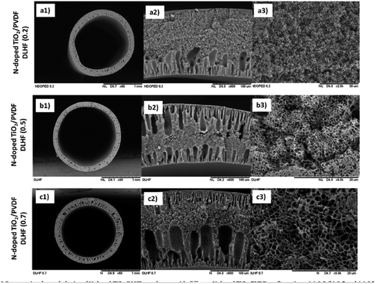 |
| | Fig. 13 SEM image of the: (a) 3.0, (b) 7.5, and (c) 10.5 wt% N-doped TiO2 in the PVDF dual layer hollow fibre membrane.62 | |
3.1.2 Electrospinning.
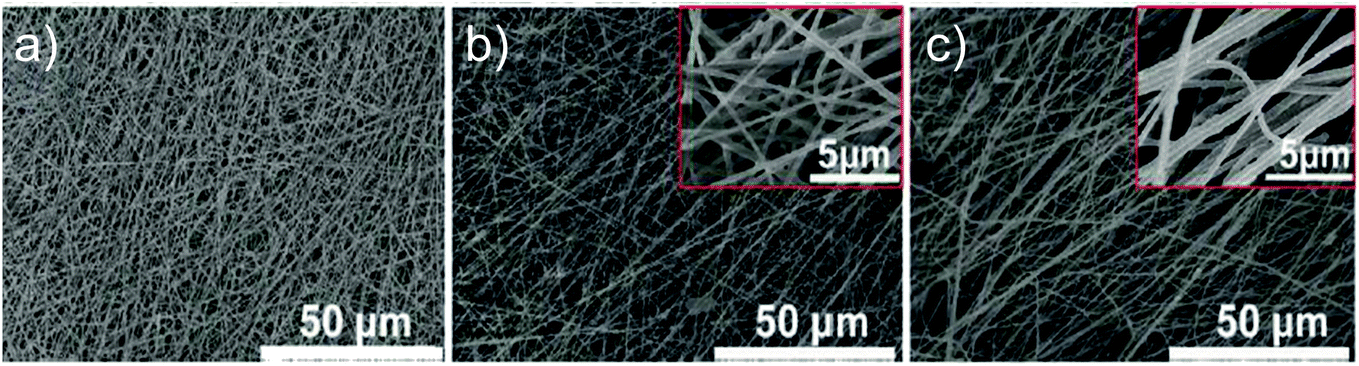
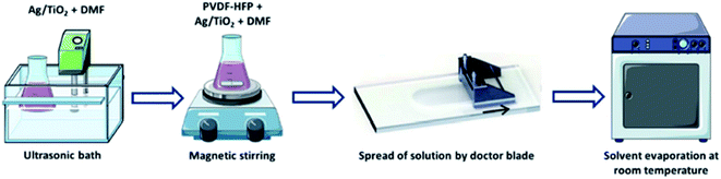
Previously, the membrane fabrication technology known as electrospinning had successfully fabricated an electrospun mixed matrix membrane consisting of a mixture of photocatalyst and polymer. According to the previous literature, the electrospinning method provides the membrane with higher porosity and a larger surface area.75 Therefore, it is stated that by electrospinning, the produced photocatalytic membrane will have better mechanical properties. The electrospinning system is illustrated in Fig. 14. A previous paper reported by Salazar et al.76 showed that Ag–TiO2/polyvinylidene fluoride-hexafluoropropylene (PVDF-HFP) electrospun membranes were prepared by electrospinning for the photocatalytic degradation of norfloxacin under UV and visible light. The degradation rate of norfloxacin was about 64.2% under UV light in 90 min, while it was 80.7% under visible light for 300 min. Norfloxacin was degraded well under visible light, as well as UV light irradiation. This is due to the higher band gap energy of TiO2 between 3.1–3.4 eV, which is suitable to be illuminated under UV light with a wavelength range of 100–400 nm.77 Besides, when Ag was doped with TiO2, the band gap tends to slightly decrease to 2.9–3.0 eV, where it allows the photocatalyst to be irradiated by visible light at a wavelength range between 400 nm to 700 nm. TiO2 nanocomposites were dispersed well in DMF, and PVDF-HFP was added afterwards. The prepared solution was poured into a syringe that was fitted with a 0.5 mm diameter steel needle. This procedure was operated by applying 14 kV voltage with a feed rate of 0.4 mL h−1. The electrospun product was collected in an aluminium plate with the distance between the needle and plate at 20 cm. By electrospinning, the membranes obtained were highly porous, non-woven fibres, and interconnected pores were formed. Fig. 15(a) indicates the smooth surface of PVDF-HFP without the presence of beads with an average diameter of 0.24 μm. In contrast, Fig. 15(b and c) show the wrinkled surface with a high average diameter of 0.32 μm due to the accumulation of nanoparticles at the fibre surface. Although the membranes with the photocatalyst show high porosity, the active photocatalytic sites for norfloxacin adsorption and light radiation exposure decreased due to the encapsulation and aggregation of the TiO2/Ag nanoparticles. This is due to the blocking of the active site, which did not receive enough light penetration for the formation of the radical to degrade the norfloxacin.
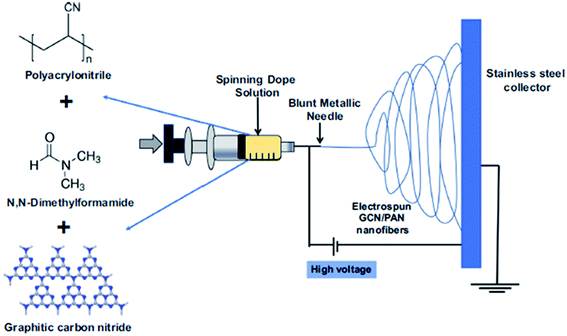 |
| | Fig. 14 Schematic diagram of the electrospinning method for the mixed matrix membrane.78 | |
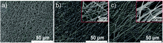 |
| | Fig. 15 SEM images of the electrospun (a) PVDF-HFP membrane, (b) TiO2-PVDF-HFP membrane, and (c) TiO2/Ag-PVDF-HFP membrane.76 | |
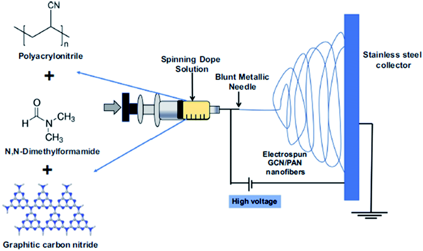
According to Alias et al.,78 graphitic carbon nitride (g-C3N4) powder was mixed with DMF and polyacrylonitrile (PAN) as a dope suspension. The dope suspension was then used in the electrospinning process with the voltage of 15 kV and flow rate at 1 mL h−1. The distance between the electrospinning needle and collector was 18 cm. The electrospun collector used in this study was a stainless steel plate coated with aluminum foil. A thin sheet of g-C3N4/PAN nanofibers was collected by peeling off the electrospun product at the collector by hand. The electrospun product was an interconnected open pore structure. The uniform distribution of g-C3N4 along PAN was observed due to the nodule-less structure formed with a mean diameter of synthesized bulk graphitic carbon nitride (bg-C3N4) equal to 207 nm, while the nanosheet graphitic carbon nitride (nsg-C3N4) was 262 nm. In addition, bg-C3N4 has numerous lumps due to the bulky shape embedded in the nanofibers. Therefore, nsg-C3N4 produced a uniform, smooth and straight length structure due to the lower number of lumps formed. The bulk properties are different from those of the nanosheet. The nano size of the photocatalyst shows better efficiency for water treatment and recycling ability due to their smaller size compared to the bulk photocatalyst. The smaller the catalyst size, the larger the numbers of atoms assembled, which lead to an increase in the surface to volume ratio. Moreover, it will enhance the number of active sites and interfacial charge carrier transfer rates. Thus, helps in increasing the catalytic efficiency.79
The other literature study that applied the electrospinning method in fabricating mixed matrix membranes can be seen through.80 A mixed matrix membrane containing a polyamide-6 (PA-6) nanofiber, and the commercial and colloidal TiO2 photocatalyst has been successfully fabricated by electrospinning procedure, and successfully degraded up to 99% of methylene blue after 6 hours of UV illumination. Before the electrospinning process took place, the solutions of 16 wt% of PA-6 and 0.07 wt%, 0.30 wt%, 0.12 M and 0.50 M of TiO2 nanoparticles mixture were prepared first. The solution was poured into the multi-nozzle fed by syringe in order to produce the various thicknesses of the electrospun fiber membranes. The electrospinning procedure was operated at 20 kV voltage with the distance between the needle and collector at 10 cm. However, the higher concentration of the TiO2 nanoparticle can contribute to the agglomeration in the polymer membrane. This give a bad effect on the blending of the mixed matrix membrane during the spinning procedure, as can be seen in Fig. 16. When the amount of TiO2 was increased beyond the optimum concentration, the light penetration depth into the active site was reduced and consequently diminished the scattering of light. It is an insufficient amount of electrons to excite from the valence band to the conduction band to form holes, which then reduces the redox reaction process. Thus, it reduces the photocatalytic activity.
 |
| | Fig. 16 SEM images of the: (A) 0.12 M colloidal TiO2–PA-6 electrospun and (B) 0.50 M commercial TiO2–PA-6 electrospun.80 | |
3.1.3 Tape casting.
Tape casting is one of the facile fabrications of the membrane, which produces the flat sheet membrane. The schematic diagram of this casting procedure is illustrated in Fig. 17. The immobilization of TiO2 in the PVDF membrane structures using the tape-casting method has attracted attention in recent studies as the photocatalytic membrane in the degradation of the methylene blue dye.58 The literature written by Dzinun et al.58 explains that the flat sheet configuration of the polymeric membrane was immobilized with TiO2 by using a knife-like tool in controlling the membrane thickness and dispersion of the polymer solution. SEM with 10k zoom images in Fig. 18 show the aggregation of 6 nm and 30 nm particle sizes of TiO2 at the outer membrane surface, causing the size of the membrane to become 385 nm and 568 nm. Thus, it reduces the surface area, resulting in the low performance of photodegradation due to the larger size of the TiO2 particle. When the size of the particles is larger, a small number of atoms accumulated, which then decreased the surface-to-volume ratio.79 In the other literature study by Zangeneh et al.,81L-histidine (C,N-doped TiO2–CdS) incorporated with a PES ultrafiltration membrane was fabricated by mixing the photocatalyst, PES and PVP as the casting solution. Then, the casting solution was cast onto a glass substrate with 150 μm thickness. The glass substrate was then soaked into the distilled water bath to obtain the thin membrane film by peeling the fabricated membrane. The fabricated mixed matrix membrane was reported to successfully remove 65.26% COD at 3 bar and 150 L h−1 conditions under the irradiation of visible light.
 |
| | Fig. 17 Schematic diagram of the casting method of the mixed matrix membrane.76 | |
 |
| | Fig. 18 SEM images of the tape casting membrane with: (a) 6 nm TiO2 and (b) 30 nm TiO2.58 | |
Another literature study reported the fabrication of the flat sheet PSF/N, co-doped TiO2 membrane using the tape casting method in the degradation of 92% of eosin yellow dye under visible light irradiation.63 Before casting the membrane, the photocatalyst was prepared using the sol–gel method. Ti(OC3H7)4 was mixed with 2-propanol to produce an isopropoxide/propanol solution, while Pd(NH3)2Cl2 was dissolved in ammonia to produce an ammoniacal solution. Then, the ammoniacal solution was mixed with the isopropoxide/propanol solution. After the sol was dried at 80 °C and calcined at 500 °C for 2 hours, the N,Pd co-doped TiO2 was obtained. The N,Pd co-doped TiO2 was then further used as the photocatalyst to be embedded with polysulfone, forming a photocatalytic polymeric membrane. The PSF pellet was dissolved in NMP, and N,Pd co-doped TiO2 was added and dispersed well in the dope solution. The dope solution was spread evenly on a clean glass plate by using a casting knife with a 250 μm air gap. Then, the membrane was immersed in a deionised water bath. The membrane was obtained by peeling from the glass plate. The mixed matrix membrane was immersed in an ethanol/deionised water bath to remove the excess solvent, and then dried in air for 48 hours. According to the EDS characterization of the mixed matrix membrane, the N,Pd co-doped TiO2/PSF mixed matrix membrane revealed that the photocatalyst embedded inside the membrane had a uniform dispersion without the formation of an agglomeration. However, nanomaterials have tendency to agglomerate in a medium of organic solvent or organic polymer body.82 From the observation, a higher loading of 4% and 7% wt. of the photocatalyst inside the membrane in Fig. 19 caused the agglomeration of the nanoparticles at the near-outer surface and within the membrane pores. This led to a higher surface roughness and increase in the contact angle of the membrane, as well as the low obtained surface area, which reduced the photodegradation performance. The concentration of the catalyst is one of the factors that influences the efficiency of the photocatalysis. If a very high concentration of photocatalyst was added, the photon blocking would occur and decrease the degradation rate.73
 |
| | Fig. 19 SEM images of the tape casting of the PSF membrane with: (a) 1.0 wt%, (b) 2.0 wt%, (c) 3.0 wt% and (d) 4.0 wt% of N, co-doped TiO2.63 | |
Besides, the Cu2O/PSF ultrafiltration mixed matrix membrane was fabricated for photocatalytic ibuprofen removal.28 This paper reported that 86% of ibuprofen was successfully removed under visible light irradiation. The mixed matrix membrane was prepared by dissolving the PSF, PEG and different amounts of Cu2O in NMP solution as the membrane casting. The casting was evenly spread on a clean glass plate and peeled off after immersion in distilled water. According to the FESEM micrograph, uniform pores were formed due to the significant role of the Cu2O photocatalyst allowing the shrinkage of the polymer generated from mechanical stress during the casting process. Furthermore, the addition of Cu2O inside the membrane enhanced the formation of a wider finger-like structure of mixed matrix membrane due to the hydrophilic nature of Cu2O that improved the mass transfer solvent and non-solvent during the phase inversion procedure.83 The intensity of the photons can have an impact on the degradation activity. When the intensity of the photons absorbed was higher, the reaction rate also increased. This is due to the greater photogenerated electron–hole pair concentration, which led to a greater radical formation and the occurrence of more photodegradation.73
The other literature study that explained this method was written by ref. 70, in which the paper indicates the fabrication of the TiO2/PVDF-HFP and Ag–TiO2/PVDF-HFP mixed matrix membrane using the casting procedure. The mixture between the photocatalyst and polymer was spread well on the glass substrate using a bar coater. Then, the solution was left at room temperature for 3 days to let the solvent evaporate and undergo the liquid–liquid phase separation process before the flat sheet membrane was crystallized. Smaller pores with a diameter between 1–8 μm and larger pores formed by a double porous structure after the TiO2 nanoparticles were added can be observed from the SEM images in Fig. 20. When Ag was added with TiO2 into the membrane, the morphology showed that the pore diameter was reduced to between 1–4 μm. Both morphologies did not show any agglomeration of nanoparticles formed in the membrane. From the photocatalytic study using UV light irradiation, norfloxacin was successfully degraded up to 45% and 64% for 3 wt% TiO2/PVDF-HFP and Ag–TiO2/PVDF-HFP flat sheet membranes, respectively. Comparing the TiO2 and Ag–TiO2 nanocomposites on the degradation performance, the Ag–TiO2 materials indicated higher degradation efficiency. This is due to the presence of Ag on the TiO2 surface reducing the electron/hole recombination rate.76 Moreover, by tape casting the membrane, it helps to spread the photocatalyst well, which allowed the light to easily penetrate the active site of the photocatalyst to form an electron and holes for the redox reaction during photocatalysis.
 |
| | Fig. 20 SEM images of the flat sheet PVDF-HFP membrane with (a) TiO2 and (b) Ag–TiO2 nanoparticles.76 | |
3.1.4 Spin coating (blended).
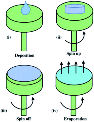
Spin coating is one of the methods in fabricating the thin sheet of membrane with high quality and uniform membrane film84 by applying a viscous liquid on a horizontal rotating disc. This method can be divided into four processes, including deposition, spin-up, spin-off and evaporation process. First, a polymer solution was deposited onto a centre of the spin coater, which is known as the substrate. This was then followed by rotating the substrate with high speed, leading to the liquid flow outwards due to the centrifugal force, or namely as spin-up stage. At the third stage or known as spin-off process, the excess polymer flowed outwards to the perimeter, and was ejected and formed accumulations. At the final stage, the polymer solution was evaporated, forming a thin solid membrane state. The spinning speed for the mass transfer kinetics during the spin coating procedure influences the membrane structure and photocatalytic performance. This method is visualized in Fig. 21.
 |
| | Fig. 21 Schematic diagram of the spin coating method.85 | |
Before this method was operated, the casting solution consisting of the photocatalyst and polymer was prepared first for further use in the spin coating procedure. The example of the preparation of the mixed matrix polymeric membrane using this method was explain by Dzinun et al.58 About 3 wt% of TiO2 nanoparticles powder was mixed with 82 wt% of DMAc and 15 wt% of PVDF in a Scott bottle with a stirring speed of 400 rpm for 1 day, which was labeled as the casting solution. After that, the casting solution was further used in the spin coating method by dropping 2 mL of casting solution on a Petri dish with a spin coater (Aiden) at various spinning speeds for 30 s. The membrane produced was immediately immersed into a water bath, and went through post treatment by immersing the membrane into 50% of diluted ethanol for 1 hour, followed by 100% concentrated ethanol for another 1 hour in order to improve the wettability and pore collapse.58 From this method, it is stated that the thickness of the membrane depends on different spinning speeds. The structure and outer surface of the produced membrane changes due to the process and solvent evaporation. The higher the spinning speed, the more the solvent evaporated, which led the film produced to become thinner. Moreover, by using this method, TiO2 was uniformly dispersed in the membrane through the centrifugal force produced by spinning effect. Therefore, the higher the spinning speed, the dispersion of the photocatalyst will be more uniform, as can be seen in Fig. 22. Furthermore, it is proved that by using the spin coating method, the membrane surface prepared was smoother than the tape casting method due to the liquid being spread evenly. In addition, the evaporation taking place is affected by the velocity of the rotating Petri dish. Besides, when the photocatalyst was evenly dispersed inside the polymer matrix, it would have a larger exposed area of photocatalyst to be irradiated with light. Hence, the light can penetrate the active site of the photocatalyst easily for the photodegradation process. The mixed matrix membrane prepared using this method has been successfully used to degrade 100% of methylene blue under UV light irradiation in 60 min.58
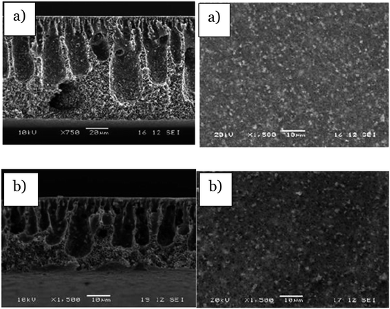 |
| | Fig. 22 SEM images of the cross-section and outer surface of the membrane via spin coating with a speed of (a) 500 rpm and (b) 1300 rpm.58 | |
The other previous literature also reported that the spin coating method has been successfully implemented to form a thin layer of ZnO/polymer resin for the photodegradation of methylene blue. To form the thin layer, citric acid and Zn(NO3)2·6H2O were first dissolved in water at 70 °C. Then, ethylene glycol was added and the temperature was increased to 90 °C to obtain the homogenous resin. Samarium nitrate was later added to the mixture to obtain the Zn/samarium resin. To fabricate the photocatalytic polymer resin, a silicon substrate was used as a support to be deposited by the mixture of Zn/samarium polymer resin solution during the spin coating. The mixture solution was then poured onto the silicon substrate by spin coating at 7000 rpm for 30 s. The thin layer composed of mix Zn/polymer resin was formed and further annealed at 350 °C for 1 hour, and then dried at 700 °C to obtain the thin solid layer.86 The photocatalytic membrane successfully degraded 90.4% of methylene blue under UV-Vis light irradiation. The FESEM image in Fig. 23 shows the formation of small and larger grains formed due to the high energy applied during spin coating. The growth of larger grains was due to the coalescence of smaller grains. Overall, the distribution of the photocatalyst was uniform due to the smaller photocatalyst being used. Hence, it increased the surface area and enhanced the photodegradation of methylene blue.
 |
| | Fig. 23 FESEM micrograph of ZnO: 4% samarium distribution on the membrane.86 | |
The active sites of the photocatalyst played an important role in determining the photocatalytic activity. According to Hsiung et al.,87 a few of the TiO2 active sites were detected, which influenced the photodegradation rate. The photoactive species of commercial TiO2 and synthesized TiO2 by sol gel method were studied using X-ray absorption near edge structural (XANES) spectroscopy. From the X-ray absorption near-edge structural (XANES) spectra, photocatalytic species such as A1 (4969.4 eV), A2 (4970.5 eV) and A3 (4972.3 eV) fit with the relative peaks at (101), (004) and (200) in the TiO2 photocatalyst, which are attributed to the three 1s–3d transition active sites, including for the four-(TiO4), five-((Ti![[double bond, length as m-dash]](https://www.rsc.org/images/entities/char_e001.gif) O)O4) and six-(TiO6) coordinated Ti structural species, respectively, as stated in Table 7. The synthesized TiO2 exhibited a higher surface area than the commercial TiO2. Thus, methylene blue was degraded up to 90% using the synthesized TiO2 in 20 min rather than commercial TiO2, which only shows 42%. Since the A2 species, ((TiO)O4), was enriched on the surface of the synthesized TiO2, it contributes as the main active site during the photocatalytic degradation of methylene blue.
O)O4) and six-(TiO6) coordinated Ti structural species, respectively, as stated in Table 7. The synthesized TiO2 exhibited a higher surface area than the commercial TiO2. Thus, methylene blue was degraded up to 90% using the synthesized TiO2 in 20 min rather than commercial TiO2, which only shows 42%. Since the A2 species, ((TiO)O4), was enriched on the surface of the synthesized TiO2, it contributes as the main active site during the photocatalytic degradation of methylene blue.
Table 7 Different active sites that enhance the photocatalytic degradation
| Photocatalyst |
Active sites |
XRD peaks |
Pollutant |
Time (min) |
Photocatalytic degradation using UV lamp (%) |
References |
| TiO2 |
TiO4 |
101 |
Methylene blue |
20 |
90 |
87
|
| (TiO)O4 (main) |
004 |
| TiO6 |
200 |
| ZnO |
Zn2+ |
002 |
Methylene blue |
120 |
77 |
88
|
Other literature reported that the active species of ZnO depends on the exposed lattice plane. From the XRD spectra, 2θ at 34.4° (002) shows the highest peak, which was enriched in the ZnO photocatalyst.88 It was stated that the 002 facet absorbed UV radiation, which scatters light beyond the optical path length due to the honeycomb network structure. Moreover, the electric dipole was produced from the 002 polar surface, consisting of positive Zn-terminated (002) facets and negative O-terminated (00-2) facet. Furthermore, the exposed (002) facet was attributed to the increase of interstitial O2 on this facet. From the XPS spectra, the highest peak with a binding energy of 1021.1 eV and 1044.2 eV confirmed that Zn2+ existed abundantly as Zn ions. The Zn2+ ionic sites on the (002) facets adsorbed the oxygen, resulting in a thin O2− layer that helped in the redox reaction. Thus, it acted as the active sites that enhance the photocatalytic reaction. This can be seen when methylene blue has been successfully degraded up to 77% in 120 min using UV light irradiation. The differences of the active sites are summarized in Table 7.
In summary for this section, a mixed matrix membrane containing a photocatalyst that has been fabricated by various methods influences the morphology and performance in the photocatalytic activity. Mostly, the mixed matrix membrane provides benefits for water treatment, as the membrane produced is robust and can reduce the leaching of the photocatalyst since it is embedded inside the polymer matrix. However, it also shows drawbacks when a higher amount of photocatalyst is used. The photocatalyst may not be spread well inside the polymer matrix, which leads the photocatalyst to lump together and reduce the surface area. Thus, it blocks the active site of the photocatalyst from receiving enough light penetration. Besides, other factors that affect the photodegradation activity are the size and structure of the photocatalyst being used. The smaller the size of the photocatalyst, the larger the surface area.73 Hence, it enhances the light penetration towards the active site of the photocatalyst, which increases the photocatalytic performance. The single and dual layer of the hollow fibre mixed matrix membrane can be fabricated using dry–wet spinning and dry–wet co-spinning, respectively. Between these two procedures, the dual layer shows a more promising membrane than the single layer due to the photocatalyst being well distributed in the membrane, which enhances the light passing through the active sites of the membrane, resulting in the high photocatalytic degradation of the pollutant. Moreover, the hollow fibre configuration provides a higher surface area and easy flow for water flux. Besides, the electrospinning shows advantages, in which the photocatalysts can spread well inside the membranes. However, when a higher amount of photocatalyst was added, there was a formation of lumps inside the membrane that restricted the penetration of light, resulting in the low removal of the pollutant. Other methods that can be used to fabricate the mixed matrix membrane are tape casting and spin coating. Both methods provide a uniform distribution of the photocatalyst inside the membrane. However, by using the tape casting method, agglomeration of the photocatalyst was obtained when a higher amount of photocatalyst was used. Besides, the spin coating needs the high energy of speed to ensure the uniform and good photocatalyst distribution. For the mixed matrix membrane, it can be concluded that the photocatalyst, CaCu3Ti4O12, blended with the PES hollow fibre membrane using the dry–wet co-spinning technique was the most promising method in the photodegradation of the dye.72 This is due to the faster degradation of rhodamine B under UV light irradiation up to 74.83% removal only within 40 min. Besides, the hollow fibre configuration provides a higher surface area for light penetration towards the active sites of the photocatalyst during photodegradation. The summary of the photocatalyst immobilized into the polymeric membrane is shown in Table 8.
Table 8 Summary of the mixed matrix polymer membrane methods for photocatalytic activity
| Photocatalyst |
Polymer type |
Method |
Configuration |
Light irradiation |
Time (min) |
Pollutant |
Photocatalytic factor |
Removal (%) |
References |
| N-doped TiO2 |
PVDF |
Dry–wet Co-spinning |
Hollow fibre membrane |
UV (30 W, 312 nm) |
360 |
Reactive Black 5 |
High concentration of photocatalyst |
100 |
62
|
| Visible |
75 |
| CaCu3Ti4O12 |
PES |
Dry–wet spinning |
Hollow fibre membrane |
UV-C (360 W) |
40 |
Rhodamine B |
High concentration of photocatalyst |
74.83 |
72
|
| Ag–TiO2 |
PVDF-HFP |
Electrospinning |
Electrospun mat |
UV |
90 |
Norfloxacin |
Suitable band gap for irradiation |
64.2 |
76
|
| Visible (xenon, 600 W m−2) |
300 |
57.6 |
| Graphitic carbon nitride (g-C3N4) |
PAN |
Electrospinning |
Electrospun mat |
Visible (white, 30 W, 420 nm) |
300 |
Methylene blue |
Small size of photocatalyst |
97.3 |
78
|
| TiO2 |
PA-6 |
Electrospinning |
Electrospun mat |
UV (300 W, 5 mW cm−2) |
360 |
Methylene blue |
High concentration of photocatalyst |
99 |
80
|
| C,N-doped TiO2–CdS |
PES |
Tape casting |
Flat sheet |
Visible (halogen, 500 W, 400 nm) |
120 |
COD |
Well dispersion of photocatalyst |
65.2 |
81
|
| N, co-doped TiO2 |
PSF |
Tape casting |
Flat sheet |
Visible (450 W, 1000 W m−2) |
180 |
Eosin yellow |
High amount of photocatalyst |
92 |
82
|
| TiO2 |
PVDF |
Tape casting |
Flat sheet |
UV |
60 |
Methylene blue |
Larger photocatalyst size |
95 |
58
|
| Cu2O |
PSF |
Tape casting |
Flat sheet |
Visible (250 W, 390–800 nm) |
60 |
Ibuprofen |
High intensity of photon |
86 |
28
|
| Ag–TiO2 |
PVDF-HFP |
Tape casting |
Flat sheet |
Visible (xenon, 600 W m−2) |
300 |
Norfloxacin |
Lower band gap |
80.7 |
76
|
| TiO2 |
PVDF |
Spin coating |
Flat sheet |
UV |
60 |
Methylene blue |
Well dispersion of photocatalyst |
100 |
58
|
| ZnO |
Polymer samarium resin |
Spin coating |
Flat sheet |
Visible |
420 |
Methylene blue |
Uniform dispersion of smaller photocatalyst due to high energy spin coating |
90.4 |
86
|
3.2 Deposition onto the membrane surface
Nowadays, the coating method is widely used in order to immobilize the photocatalyst onto the membrane structure, such as sputtering,89 dip coating,90 electrospraying,80 atomic layer deposition,91 and others. The attachment of the thin layer photocatalyst on the polymer membrane as a support plays a crucial role in minimizing the agglomeration of nanoparticles, and provides better performance in the photocatalytic degradation activity. Besides, the coating polymer with photocatalyst seems to provide a more promising technique, rather than immobilized into the membrane due to the easier accessibility of the photocatalyst particle incorporated with the polymer membranes, as well as one-step technique. In addition, the mixed matrix membranes can experience an agglomeration of the photocatalyst nanoparticle, which allows the obstacles to produce a uniform surface membrane. Besides, the agglomeration can clog the membrane pores, which can cause a surface defect that leads to the reduction of the surface area and photocatalytic activity.92 This section will list several coating techniques that have been reported in the previous literature.
3.2.1 Sputtering technique.
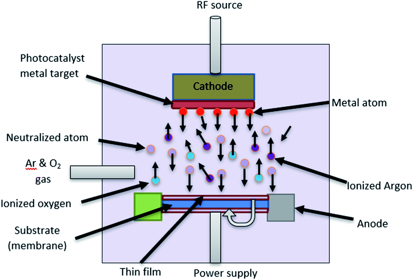
One of the coating techniques of the photocatalyst on the polymer support is sputtering technique. Sputtering is the process of the ionized ion from the target material (metal or metal oxide) bombarding the substrate (e.g., polymer, glass, silicon), which then forms a thin layer deposited on the surface of the polymer.25 This deposition process was carried out in a vacuum chamber by flow in the argon and oxygen gas, as well as working pressure to allow the ion bombardment to occur. Moreover, this technique is known as a cost-effective method because of the uniform sputtered layer formed, and less impurities are generated due to no chemicals being used.93 In addition, this is one of the promising techniques for photocatalyst coating in a larger area production due to its single-step coating. Fig. 24 shows the schematic illustration of the sputtering process.
 |
| | Fig. 24 Schematic diagram of the sputtering technique. | |
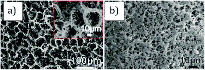
As mentioned by Tavakolmoghadam et al.,94 TiO2 was successfully sputtered on a commercial PVDF flat sheet membrane through the DC reactive sputtering technique. An electric field generated from a power source will ionize the argon gas to produce Ar+ ion, which then bombards the Ti target to eject the Ti atoms. The Ti atoms will then react with O2 to produce TiO2 and next bombard the PVDF surface, which results in a thin layer of TiO2. From this technique, it is proven in Fig. 25 that the uniform layer and small nanoparticles of TiO2 were successfully deposited, which can avoid the blockage of pores. Thus, it is easy for the light penetration to reach the active sites of the photocatalyst. However, by using this method, it is stated that the bond between the sputtered TiO2 and PVDF surface was not tightly attached together, which may cause TiO2 leaching during the cleaning process. Thus, it can reduce the capability and applicability for the long-term filtration process. The modification of the polymer membrane was needed to ensure the strong attachment of the sputtered photocatalyst on the surface of the membrane. Thus, this reduces the drawback of the photocatalyst leaching during the treatment.
 |
| | Fig. 25 SEM image of the modified PVDF membrane with the deposition of TiO2 (ref. 78). | |
Recently, Marcelino et al.95 reported on the good photocatalytic activity of TiO2 sputtered on polyethylene terephthalate (PET) in the removal of contaminants of emerging concern, specifically for the fungicide carbendazim (CBZ) and anthropogenic pollution tracer caffeine (CAF) up to 39% under a combination of UV and visible light irradiation. It is stated that TiO2 was successfully deposited onto the PET flat sheet surface by using the high power impulse magnetron sputtering (HiPIMS) technique. The argon and oxygen flow rate used in this sputtering procedure was fixed at 3.0 sccm and 50 sccm, respectively. The power supply was set at 700 Hz with a deposition time of 60 min, as well as the target substrate distance being equal to 100 cm. By using this method, the thin film deposited was smooth and exhibited denser surfaces, rather than the coating using a DC magnetron sputtering. This is because the power applied was high energetic pulses with frequency (<1.5 kHz), current density (0.2 A cm−2) and power density (>kW cm−2) on the target. Besides, the temperature sent to the substrate was also lower compared to the DC magnetron. Furthermore, the HiPIMS coatings can provide strong adhesion and higher crystallinity compared to the other magnetron sputtering.96
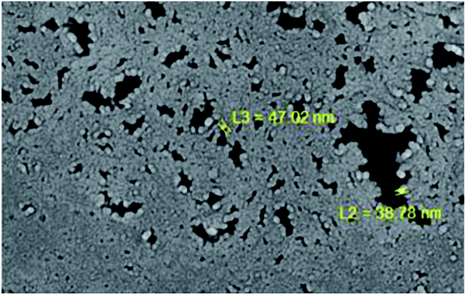
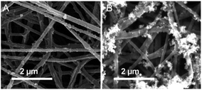
The sputtering technique of the material on the polymer surface is still lacking in the literature. Mostly, this technique was used to deposit the material or photocatalyst on the glass, silicon and quartz substrate. The sputtering technique has been proven to be successfully implemented in the sputtering of TiO2 and Cu2O thin film onto the substrate, namely n-type Si (100) wafers and glass plate composed of indium tin oxide (ITO). The TiO2/Cu2O thin film was deposited by DC magnetron sputtering using pure Cu and Ti target. The sputtering process took place by applying 120 W of DC power in 30 min with an argon flow rate of 4 cm3 s−1, while the oxygen flow rate was 1.5 cm3 s−1 for TiO2 sputtering.
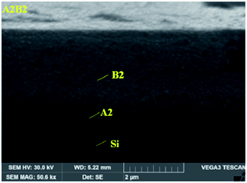
In contrast, Cu2O was deposited later above the TiO2 layer with 80 W power in 40 min by applying 3.0 cm3 s−1 for the oxygen flow rate, while the argon flow rate was 2.0 cm3 s−1. As mentioned in the paper, the closer the substrate was to the target, the higher the thickness of film deposited, as well as increasing the value of the grain sizes. Besides, by increasing the thickness of the thin film, the produced layer showed more uniformity, more roughness on the substrate surface and less deformation.97 The micrograph of TiO2 and the Cu2O coating on the membrane is shown in Fig. 26. The Cu2O layer was thicker than TiO2 due to the close distance between the substrate and target. The properties of the sputtered material depend on several factors, including power, argon–oxygen flow rate, time and target–substrate distance. In general, the higher the sputtering power, the higher the film formation rate. Besides, the longer the deposition time, the thicker the sputtered film on the substrate surface. Hence, this increases the size of the grains of the coating material. The argon and oxygen flow rates also play important roles in the sputtering procedure. The higher flow rate of argon helps to ionize the target to eject the target atoms more easily, while the oxygen flow rate acts as a helper to produce metal oxide. For example, titanium atoms from the target will react with oxygen, forming TiO2. The pressure of the sputtering system also affects the quality of the coating film on the substrate. From the previous literature, the high pressure during the sputtering procedure can lower the speed of the sputtered atoms that reach the substrates. Thus, it can cause the particles to collide with the gas, and unfortunately return back to the sputtered surface.98
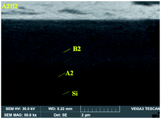 |
| | Fig. 26 SEM image of (A2) TiO2 and (B2) the Cu2O layer on the Si membrane.97 | |
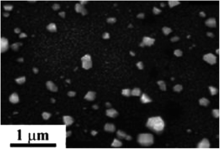
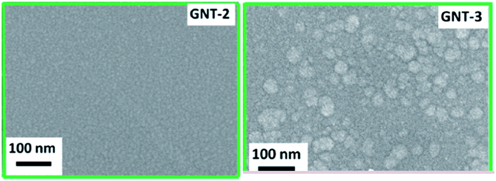
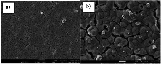
Other studies have also discovered the sputtering process of nickel oxide (NiO) on graphene oxide thin films using the direct current radio frequency sputtering technique, which is labeled as GNT. As mentioned by Jilani et al.,89 the NiO metal oxide pure target was used to sputter the NiO thin film with the distance between the target and substrate at 15 cm. The DC power of 200 W with an O2 flow rate was 40 sccm, and a base pressure equal to 9 × 10⁻⁷ torr were applied during the sputtering procedure. According to this paper, GNT exhibited good photocatalytic activity of 2-chlorophenol. The FESEM micrograph in Fig. 27 shows that the size of NiO in GNT-3 increased with increasing time deposition. In addition, the agglomeration of NiO occurred, which blocked the pores. When the deposition time was increased, the film became thicker and the grain size also increased. When the size of NiO increases, it may lump together and reduce the surface area of NiO. When the surface area of NiO is reduced, it causes less light penetration. Moreover, the charge carrier from the upper NiO layer to the inner GO layer became poorer when the deposited film was thicker. Moreover, a photoluminescence (PL) study stated that the thicker deposited film produced high PL intensity, which indicates the high rate of the recombination of the electron–hole.89 Hence, this reduces the photocatalytic activity.
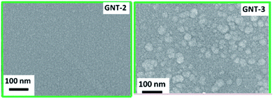 |
| | Fig. 27 FESEM micrograph of GNT-2 and GNT-3 with a deposition time of 800 s and 1200 s, respectively.89 | |
Another paper that mentions the sputtering process can be seen in the literature by Singh et al.99 The sputtering process was achieved by depositing the TiO2 onto silica glass substrates from the titanium metal target using the radio frequency (RF) magnetron sputtering technique. The deposition of TiO2 thin films was carried out at 2.5 × 10⁻³ torr, and the temperature of the substrate was maintained at 200 °С. The gas pressure, RF power and temperature of the substrate were optimized. The thickness of the TiO2 thin film deposited was varied at 20 nm, 40 nm, 80 nm and 100 nm, which referred to T2, T4, T8 and T10, respectively. From the Tauc plot, the band gap of T2, T4, T8 and T10 were 3.4 eV, 2.8 eV, 3.0 eV and 2.9 eV, respectively. This shows that the optical properties changed with increasing film thickness. Among these samples, T4 possesses the highest degradation percentage of methylene blue up to 83% under sun light irradiation only in 45 min due to the lower band gap, which indicates the excellent efficiency of the sputtered TiO2 in the photodegradation of the dye. The band gap of the catalyst is necessary for photocatalytic study. When a lower band gap was used, the wavelength between 380–750 nm was more desirable for photocatalytic applications (effective sunlight region). Basically, the lower band gap can absorb light at higher wavelengths due to the lower energy requirement for the electron transition from the valence band to the conduction band.73 Overall, to optimize the coating layer, the operational condition such as power supply, argon-oxygen flow rate, time and target–substrate distance need to be adjusted and considered.
3.2.2 Dip coating.
This technique is employed by immersing the support, such as a polymer, into a solution for coating it. This is then followed by the removal of the support from the solution at a slow speed. This technique will produce different thicknesses of the coating layer from thinner to thicker film of the photocatalyst. Before the deposition occurs, the supports must first be cleaned and dried to avoid any contamination. The photocatalyst solution needs to be sonicated first to avoid any agglomeration of the photocatalyst particle on the surface after the dip out.100 The schematic diagram of the dip coating is shown in Fig. 28.
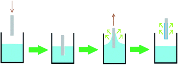 |
| | Fig. 28 Diagram of the dip coating method.100 | |
According to Luo et al.,90 the PVDF flat sheet membrane was modified by coating layer-by-layer with a 3D TiO2/poly (sodium styrenesufonate) (PSS) photocatalyst that had been successfully fabricated using the dip coating method. It was expected that by using this photocatalytic membrane, 91.42% Lanasol Blue 3R was successfully degraded under UV light irradiation. As mentioned in this paper, the PVDF membrane was dipped in 2 g L−1 TiO2 solution for 15 min, followed by dipping in PSS solution for another 15 min. Then, the membrane surface was dipped again in TiO2 solution to form the layer-by-layer film coated on the surface. For every deposition step between TiO2 and PSS, the membrane was first dipped in distilled water to obtain the solid film in order to avoid the two photocatalysts being mixed together. During the dip coating procedure, the photocatalyst solution needs to be stirred to avoid any sedimentation of particles at the bottom of the solution. For the last step, the layer-by-layer coating membrane experiences the post treatment with ethanol and distilled water, and is then further dried in the oven for 90 min at 60 °C. Moreover, before characterization and analysis, the membrane was stirred vigorously in distilled water to remove any unstable attached photocatalyst. SEM images in Fig. 29 indicate that the deposited granules increase with increasing layers, resulting in a porous structure of membranes that make it into the hydrophilic membrane. The porous nanostructures gained much attention due to the larger accessible surface morphology, which is easier for light absorption. Besides, the structure of the catalyst also plays a significant role in the photocatalytic performance. Basically, TiO2 has three phase structures, namely rutile, anatase and brookite. Among these three phases, anatase has high photocatalytic activity due to its structural stability. Moreover, the available vacancies in TiO2 make the photoexcited electron easy to be trapped. Hence, the hole and electron are separated.101 As a result, it is possible to reduce the charge recombination and enhance the photocatalytic efficiency.
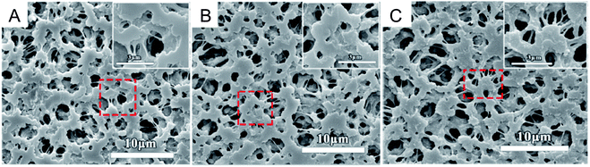 |
| | Fig. 29 SEM image of (A) 1 layer, (B) 3 layers and (C) 5 layers of the TiO2 PSS membrane.90 | |
The other paper that described the dip coating method can be seen through.102 The polypropylene (PP) hollow fibre membrane was modified by forming a thin layer on the membrane surface by dip coating into the mixture of PSF/PEG400/ZnO solution to improve the anti-organic fouling properties. In addition, these two-layer membranes were stated to be a promising membrane in removing 70% of humic substances from peat water. Besides, the dip-coating method can help in increasing the hydrophilicity of the hydrophobic membrane that is suitable for water treatment. Before the dip-coating procedure was applied, the coating solution needed to be prepared by dissolving the PSF, PEG400 and ZnO into the DMAc solution. Then, the polypropylene hollow fibre membrane was dipped into the coating solution for 2 s and 10 s. After that, the PP hollow fibre membrane was taken out and further dried at room temperature to remove the solvent and form a thin solid layer coating. Thus, this dip coating technique was declared as a simple technique to deposit a coating layer onto the polymer membrane surface. When 40% of ZnO was deposited on the membrane, the SEM image in this literature proves that the aggregation of the ZnO particles with larger pores decrease the interconnection of the polymer during the formation of the membrane, and creates voids in the polymeric layer. The time taken for the sample dip into the solution, type of solution and surface of the sample were the significant conditions that needed to be examined to obtain the optimized coating layer.
3.2.3 Electrospraying.
Electrospraying is one of the methods that is closely related to electrospinning. It comes out with benefits, such as low energy consumed, and provides the good potential in the fabrication of nanoparticle coatings. It seems that by electrospraying the photocatalyst nanoparticles onto the polymer substrates, it will produce the efficient performance of the photocatalytic activity. In addition, this technique possesses several advantages, such as a simple coating technique for large area deposition.100,103 The nanoparticles dispersed through the syringe needle will produce narrow nanoparticle size distributions. A substrate or collector will be placed horizontally to the needle. In contrast, a small motor with flexible speed is needed to rotate the collector so that it will spray uniformly.104 The previous problems related to the coating methods are nanoparticle leaching due to the unstable attachment of nanoparticles onto the polymer substrates. To overcome this disadvantage, electrospraying can become one of the promising methods.100 The schematic diagram of the electrospraying method is shown in Fig. 30.
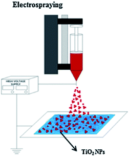 |
| | Fig. 30 The schematic diagram of the electrospraying method of the photocatalyst onto the substrate.105 | |
As mentioned by Ramasundaram et al.,105 TiO2 was dispersed inside the DMF solution, which was then electrosprayed onto both sides of the electrospun PVDF mats with the distance between the needle and PVDF mats at 100 mm by applying 15 kV power. The PVDF-TiO2 fibre coating was then dried overnight at 120 °C under vacuum. From the SEM images in Fig. 31, TiO2 droplets were deposited in a single spot on the PVDF mat. The individual and small aggregations of TiO2 accumulated, becoming circular clusters with an average size of the TiO2 clusters at approximately 20 nm. The number of clusters increased as the volume of TiO2 loading increased. By using this method, it was stated that the PVDF electrospun membrane coated with TiO2 using the electrospraying technique improved the photocatalytic activity, which completely degraded Bisphenol A, 4-chlorophenol and cimetidine in aqueous solution under UV irradiation within 100, 100 and 40 min, respectively. The clusters scattered on the overall surface of the electrospun PVDF mat, which helps in increasing the exposed area for TiO2 to be penetrated by light. This is due to the active surface area of the photocatalyst improving the light penetration during photodegradation.
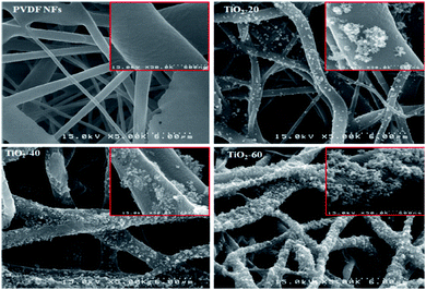 |
| | Fig. 31 SEM images of the TiO2 deposition of the PVDF mat.105 | |
Besides, the same technique has been successfully implemented in previous literature written by Ryu et al.106 Ag–TiO2 photocatalyst nanoparticles were electrosprayed onto the nylon 6,6 polymer electrospun surface for methylene blue degradation under visible light illumination. During the electrospraying procedure, the Ag–TiO2 solution was electrosprayed by following several parameters. The stainless-steel spinneret with an inner diameter of 0.51 mm, 12 kV power and 10 cm distance between the spinneret and collector was applied. Moreover, 2.5 mL h−1 flow rate of coating solution was performed in producing a thin film of photocatalyst onto the polymer electrospun surface. The prepared sample was then pressed for 2 min using a hydraulic press at 100 °C with pressure at 1000 psi to make the Ag–TiO2 strongly attached onto the polymer surface, as well as prevent leaching. For the last step, the sample was washed with a dilute methanol solution to remove any excess unbound photocatalyst, and dried at room temperature for 24 hours. This electrospraying method was revealed to coat a thin layer film on the polymer surface, and is a simple method that can be implemented to save time. The SEM micrograph in Fig. 32 showed that the electrosprayed Ag–TiO2 was evenly dispersed on the membrane surface without the formation of a large photocatalyst aggregation, resulting in it being tightly attached on the surface after heat-pressing treatment.
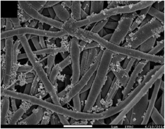 |
| | Fig. 32 SEM micrograph of the electrosprayed Ag–TiO2 on the membrane surface.106 | |
Furthermore, as mentioned in another past paper by Ramasundaram et al.,107 the TiO2 nanoparticles were electrosprayed onto the steel mesh/PVDF substrate. Steel mesh undergoes dip coating in PVDF solution to form a double layer substrate. The substrate was then further electrosprayed with TiO2 to be utilized in the photocatalytic degradation of methylene blue and methyl orange dyes. The TiO2 solution was electrosprayed on both sides of the prepared substrate with the conditions of 20 kV power, 6 mL h−1 flow rate, and the distance between the needle and collector gap was 10 cm. The sample obtained was further pressed under heat treatment with several temperatures by applying 100 MPa pressure. Lastly, the sample was immersed in stirred deionized water overnight to remove any unbound TiO2 nanoparticles, and dried under vacuum for 5 hours at 60 °C. The substrates were fully covered with aggregated TiO2. By implementing this promising technique, electrospraying offers easy control of the film thickness, an even distribution of the coating film, and faster time deposition because it did not require a calcination step. Overall, the voltage power and the distance between the sample and substrate were important in optimizing the process condition.
3.2.4 Atomic layer deposition.
A previously published paper has recorded the potential of the surface modification of polymer membranes with the immobilization of the photocatalyst onto the membrane surface using atomic layer deposition. Despite the polymer membrane, this technique also shows outstanding performance in depositing a thin film on another substrate surface. Moreover, the thin film produced was strongly attached to the surface, and can prevent the leaching of the photocatalyst during the water treatment analysis.108 Besides the water treatment, atomic layer deposition is also a promising technique in various applications, such as photovoltaics, energy conversion, and transistors, and is used in display devices that need a precise thickness of the film coating, conformity and uniformity.109 A chamber equipped with nitrogen flow and the precursor as the photocatalyst source to be deposited was needed in this study. The atomic layer deposition process is shown in Fig. 33, while the schematic diagram of the atomic layer deposition technique is illustrated in Fig. 34.
 |
| | Fig. 33 Atomic layer deposition process.110 | |
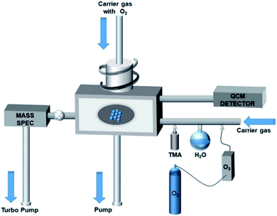 |
| | Fig. 34 Diagram of the atomic layer deposition technique.111 | |
The previous paper mentioned by Li et al.91 has successfully implemented the atomic layer deposition method by coating the flat sheet PVDF membrane with a 3D layer of TiO2/ZnO. Before the coating procedure can take place, the PVDF membrane must be dried in the ALD chamber at 110 °C for 30 min. During the deposition process, titanium tetraisopropoxide (TTIP) was used as a metal to eject TiO2 by maintaining the TTIP pulse at 100 ms with 10 s of exposure, and purged in the chamber for 30 s. Deionized water (DI) was also used in this process by maintaining the pulse at 15 ms with 10 s of exposure, and purged at 30 s. Nitrogen was used during the procedure by applying 20 sccm flow rate in order to purge the residual components after deposition. To deposit ZnO on the surface of the PVDF membrane, diethylzinc (DEZ) was used. The condition of the DEZ pulse was maintained at 20 ms, while DI water was pulsed at 15 ms. The exposure and purge condition for DEZ and DI water were the same as the coating of TiO2 from the previous one. TTIP was fixed at 80 °C, while DI water and DEZ were maintained at room temperature during the deposition procedure. FESEM micrographs indicate the surface of the TiO2/ZnO-PVDF membrane in Fig. 35. The deposited granules become larger with increasing ZnO content. According to this technique, the 3D layer of TiO2/ZnO was successfully deposited onto the PVDF membrane surface for the photodegradation of methylene blue up to 80% after 30 minutes irradiation by visible light. This is because the crystal planes of TiO2/ZnO at (101) act as an important factor in improving the photodegradation performance. The (101) planes of TiO2 are energetically high, and exhibit better photodegradation performance of the reduction of O2 to O2˙− than the (001) planes. Moreover, the hexagonal wurtzite ZnO that is formed by ALD helps in producing (100), (002), (101), (102) and (110) crystal planes. According to Wang et al.,112 the literature found that the rate of degradation is in the order of (100) > (110) > (111).
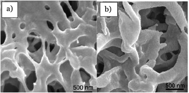 |
| | Fig. 35 FESEM images of (a) 1![[thin space (1/6-em)]](https://www.rsc.org/images/entities/char_2009.gif) :1 layer of TiO2/ZnO and (b) 1:5 layer of TiO2/ZnO deposited on the PVDF membrane by ALD.91 :1 layer of TiO2/ZnO and (b) 1:5 layer of TiO2/ZnO deposited on the PVDF membrane by ALD.91 | |
Furthermore, the previous literature indicates the atomic layer deposition method for the TiO2 coating on the surface of the flat sheet PES membrane by using a low-pressure flow type ALD reactor.108 This literature explained that the deposition process operated through a series of cyclic operations, which means that each cycle was divided into two half cycles. TiCL4 acting as the precursor was pulsed in the first half cycle using 99.9999% pure nitrogen carrier gas, and underwent the self-terminating reactions on the substrate. After that, the residual component and by-product were removed by purging the chamber. For the other remaining half cycle, a DI water pulse was used as the second precursor that was carried out in the chamber by nitrogen gas. The same action was taken, including the self-terminating reaction, and the residue was purged at the end of the procedure. The flow rate of DI water and TiCl4 were fixed at 200 sccm and 150 sccm, respectively. The pressures implemented for DI water and TiCl4 were 8 hPa and 9 hPa, respectively. In addition, the pulsing times of TiCl4/N2/H2O/N2 were 0.1 s/2 s/0.3 s/3 s, respectively, and the total cycles used to deposit the TiO2 film was 1000. The characterization result shows that the TiO2 deposited on the membrane surface was uniform, as can be seen in Fig. 36. Thus, it produced a rougher surface texture. Moreover, the atomic layer deposition is shown to be a promising technique due to increasing the mechanical strength of the membrane, and TiO2 tightly wrapped the PES membrane skeleton. Thus, it reduced the leaching of TiO2.
 |
| | Fig. 36 SEM images of the uniform distribution of TiO2 on the flat sheet PES membrane.108 | |
Another deposition of TiO2 on the polyvinyl alcohol (PVA) polymer flat thin layer using the atomic layer deposition method was reported.109 According to this study, the PVA layer was prepared by spin coating on the silicon substrate with 3000 rpm speed, and labeled as the substrate sample. During the atomic layer deposition, tetrakis (dimethylamido) titanium (TDMAT) was used as the precursor of the Ti source, while H2O acted as the reactant. Both TDMAT and H2O operated with the pulse and purge time equal to 20 ms and 20 s, respectively, in the chamber. Moreover, the temperature of TDMAT and H2O were set at 105 °C and 50 °C, respectively, while the chamber temperature was maintained at 150 °C. The pressure used in this study was 20 Pa, while the nitrogen flow rate was 20 sccm. This study implemented 100, 300, 500 and 1000 cycles to investigate the thickness of the film layer. The higher the number of cycles, the lesser the flexibility of the TiO2 nanosheet produced because different colours of the nanosheet can be seen from the optical interference at various regions. Besides, the higher the ALD cycles, the lower the surface area, which provides thicker nanosheets. Thus, it reduces the light penetration on the active sites of the photocatalyst to be reacted in the photodegradation procedure. Furthermore, the TiO2 produced by this technique shows better photodegradation of methyl orange under UV irradiation at fewer ALD cycles, which leads to an increase in its potentiality in photocatalysis applications. The structure of the nanosheet of TiO2 tends to have higher efficiency in photocatalytic study due to the smaller size of the material compared with other structures. When the size of the photocatalyst is smaller, a larger number of atoms accumulated on the surface of the catalyst, which leads to an increase of the surface volume ratio. Hence, it enhances the charge carrier transfer rates, and thereby increases the catalytic activities.113 Overall, many operational conditions, such as the nitrogen flow rate, precursor, pressure and pulsing time, are needed for operating the ALD system.
In summary for this section, the deposition of the photocatalyst on the polymeric membrane can be done with various methods. Many factors affect the photocatalytic degradation efficiency of the deposited photocatalyst, including the structure, size, band gap and crystal plane. For example, the anatase phase of TiO2 shows great photocatalytic activity due to its structural stability. Besides, the smaller size of the deposited photocatalyst also exhibited outstanding performance of the photocatalytic activity due to the exposed surface area being increased when the size decreased. Moreover, the larger and smaller band gaps of the photocatalyst were suitable to be irradiated under UV and visible light, respectively, according to their specific wavelength. The XRD crystal plane also played an important role in producing good photocatalytic activity. For example, the crystal plane of TiO2 at (101) is energetically high, which speeds up the reduction of O2 to O2˙− during the photocatalysis process. Sputtering is indicated as a promising method to sputter the photocatalyst onto the polymeric membrane due to the facile control of the film thickness, grain size and condition of the coating surface as either smooth or rough. However, the different types of polymers also affect the attachment of the photocatalyst on the membrane surface. This is important in order to avoid the leaching of the photocatalyst during the photodegradation of the pollutant in aqueous solution. Besides, the electrospraying method affected the performance of the photocatalytic activity. Although this method is faster, aggregation and larger photocatalyst clusters can be formed on the membrane surface when there is a higher amount of photocatalyst used for loading. Thus, it can block the pores and reduce the surface area for light penetration. Furthermore, the other deposition methods were dip coating and atomic layer deposition (ALD). Dip coating promotes the porous structure of the membrane due to the increasing granules from the increasing layer of excessive dip coating. Unfortunately, the aggregation of the photocatalyst occurred when a higher loading amount of photocatalyst was used. Moreover, having less ALD cycles was more favoured because it produces a higher surface area, as well as a thinner membrane that enhances the light penetration on the active sites of the photocatalyst. Thus, it provides outstanding performance of the photocatalytic activity. For depositing the photocatalyst onto the polymeric membrane, a previous article written by Singh et al.99 shows the best deposition technique. The sputtered TiO2 shows excellent photocatalytic result in that the methylene blue was degraded by 83% only within 45 min under sun light illumination. The summary of the immobilization techniques of the photocatalyst onto the polymeric membrane is revealed in Table 9.
Table 9 The summary of the immobilization techniques of the photocatalyst onto the polymeric membrane for photocatalytic activity
| Photocatalyst |
Support |
Method |
Pollutant |
Light source |
Time (min) |
Photocatalytic factor |
Removal (%) |
References |
| TiO2 |
PET flat sheet membrane |
HiPIMS sputtering |
Carbendazim |
UV-A/Vis (36 W, 370 nm) |
420 |
High energetic pulse of HiPIMS |
35 |
95
|
| Caffeine |
39 |
| NiO |
Graphene oxide flat sheet |
DC sputtering |
2-Chlorophenol |
Visible (104 W) |
210 |
High deposition time lead the increases of grains size |
40 |
89
|
| TiO2 |
Silica glass |
RF sputtering |
Methylene blue |
Sunlight (950 W m−2) |
45 |
Suitable band gap |
83 |
99
|
| TiO2/poly (sodium styrenesufonate) (PSS) |
PVDF flat sheet membrane |
Dip coating |
Lanasol Blue 3R |
UV (200 W, 385 nm) |
120 |
Stable anatase phase |
91.42 |
90
|
| TiO2 |
PVDF electrospun mat |
Electrospraying |
Bisphenol A |
UV |
100 |
Small cluster of photocatalyst |
100 |
105
|
| 4-Chlorophenol |
100 |
100 |
| Cimetidine |
40 |
100 |
| Ag–TiO2 |
Nylon 6,6 electrospun |
Electrospraying |
Methylene blue |
Visible (380–480 nm) |
720 |
Well dispersed of photocatalyst increase the surface area |
>90 |
106
|
| TiO2 |
Steel mesh/PVDF flat sheet |
Electrospraying |
Methylene blue |
UV (blacklight blue lamp, 24 W, 350–400 nm) |
120 |
Well dispersed of photocatalyst increase the surface area |
100 |
107
|
| Sulfamethoxazole |
120 |
100 |
| Microcystin LR |
70 |
100 |
| TiO2/ZnO |
PVDF flat sheet |
Atomic layer deposition |
Methylene blue |
Visible (xenon lamp, 200 W) |
30 |
Larger size of granules and energetically high crystal plane |
>80 |
91
|
| TiO2 |
PVA |
Atomic layer deposition |
Methyl orange |
UV (xenon lamp, 200 W) |
150 |
Lower ALD cycle, small size (nanosheet) photocatalyst |
80 (500 ALD cycle) |
109
|
4. Conclusions
The various modification methods for the polymeric membrane could be applied to enhance the efficiency of the photocatalytic activity under UV or visible light. This review paper has summarized the significant features of various techniques of the polymeric membrane immobilized with a photocatalyst either into or onto the membranes. From the previous review, it can be found that titanium dioxide is the most favoured photocatalyst that has been chosen by researchers to be immobilized with polymeric membranes. It is because TiO2 has great features, such as stability, availability and strong oxidation capability, to enhance the photocatalytic activity under UV light irradiation during the water treatment process. The blended and deposition techniques of the photocatalyst into and onto the polymeric membranes provide advantages and disadvantages. Mixed matrix membranes promote the strong attachment of the photocatalyst inside the membrane, which prevents the leaching of the photocatalyst during photodegradation in aqueous solution. However, a non-uniform dispersion of higher loading of the photocatalyst inside the membrane can cause photocatalyst agglomeration, which can block the pores and reduce the surface area. Thus, the lower the surface area, the lesser the light will penetrate into the active sites, resulting in low photocatalytic activity. Besides, deposition techniques of the photocatalyst (especially sputtering and atomic layer deposition) yield a uniform distribution of the photocatalyst due to the controllable deposition parameters. However, the leaching of the photocatalyst's problem might rise up depending on the condition of the polymeric membranes. Moreover, dip coating and electrospraying are simple methods, which can save time due to the easier procedure of the deposition method. However, these methods can cause aggregation and cluster formation of the photocatalyst on the membrane's surface, which reduce the photodegradation performance if the photocatalyst is not distributed evenly. Therefore, the preparation of the dope composition, stirring condition, speed, distance, concentration, pressure, flow rate and temperature should be stressed to ensure the uniform, strong attachment of the photocatalyst on the membrane, and high photocatalytic efficiency can be produced. Moreover, the suitable techniques that have been reviewed in this paper may be useful for the future study with other applications. The role of the photocatalytic study is expected to be an energy-saving technology that can contribute to global climate change mitigation by using renewable energy and less chemical input.
Conflicts of interest
There are no conflicts to declare.
Acknowledgements
The authors gratefully acknowledge the financial support from the Ministry of Higher Education Malaysia under the Fundamental Research Grant Scheme (FRGS) (Project Number: R.J130000.7809.5F161), Malaysia Research University Network (MRUN) Grant (Project number: R.J130000.7809.4L867), Higher Institution Centre of Excellence Scheme (Project Number: R.J090301.7809.4J430), and Universiti Teknologi Malaysia under the Transdisciplinary Research Grant (Project number: Q.J130000.3509.05G75) and UTM Grant Award (Project number: R.J130000.7709.5M003). The authors would also like to thank the Research Management Centre, Universiti Teknologi Malaysia, for technical support.
References
- R. C. Ding, Y. Z. Fan and G. S. Wang, High Efficient Cu2O/TiO2 Nanocomposite Photocatalyst to Degrade Organic Pollutant under Visible Light Irradiation, Chemistry Select, 2018, 3, 1682–1687, DOI:10.1002/slct.201702650
 .
.
- L. Joseph, B. M. Jun, M. Jang, C. M. Park, J. C. Muñoz-Senmache, A. J. Hernández-Maldonado, A. Heyden, M. Yu and Y. Yoon, Removal of contaminants of emerging concern by metal–organic framework nanoadsorbents: A review, Chem. Eng. J., 2019, 369, 928–946, DOI:10.1016/j.cej.2019.03.173 .
- P. Kumari, N. Bahadur and L. F. Dumée, Photo-catalytic membrane reactors for the remediation of persistent organic pollutants – A review, Sep. Purif. Technol., 2020, 230, 1–12, DOI:10.1016/j.seppur.2019.115878 .
- J. Yang, Y. Zhang, D. Zeng, B. Zhang, M. Hassan, P. Li, C. Qi and Y. He, Enhanced catalytic activation of photo-Fenton process by Cu0·5Mn0·5Fe2O4 for effective removal of organic contaminants, Chemosphere, 2020, 247, 1–8, DOI:10.1016/j.chemosphere.2019.125780 .
- W. Wang, W. Xiangxue, J. Xing, Q. Gong, H. Wang, J. Wang, Z. Chen, Y. Ai and W. Xiangke, Multi-heteroatom doped graphene-like carbon nanospheres with 3D inverse opal structure: A promising bisphenol-A remediation material, Environ. Sci.: Nano, 2019, 6, 809–819, 10.1039/C8EN01196F .
- M. Bassyouni, M. H. Abdel-Aziz, M. S. Zoromba, S. M. S. Abdel-Hamid and E. Drioli, A review of polymeric nanocomposite membranes for water purification, J. Ind. Eng. Chem., 2019, 73, 19–46, DOI:10.1016/j.jiec.2019.01.045 .
- D. Liu, Z. Huang, M. Li, X. Li, P. Sun and L. Zhou, Construction of magnetic bifunctional β-cyclodextrin nanocomposites for adsorption and degradation of persistent organic pollutants, Carbohydr. Polym., 2020, 1–3, DOI:10.1016/j.carbpol.2019.115564 .
- L. Lai, H. Zhou and B. Lai, Heterogeneous degradation of bisphenol A by peroxymonosulfate activated with vanadium-titanium magnetite: Performance, transformation pathways and mechanism, Chem. Eng. J., 2018, 1–50, DOI:10.1016/j.cej.2018.05.134 .
- M. Bellardita, G. Camera-Roda, V. Loddo, F. Parrino and L. Palmisano, Coupling of membrane and photocatalytic technologies for selective formation of high added value chemicals, Catal. Today, 2020, 340, 128–129, DOI:10.1016/j.cattod.2018.09.024 .
- J. You, Y. Guo, R. Guo and X. Liu, A review of visible light-active photocatalysts for water disinfection: Features and prospects, Chem. Eng. J., 2019, 373, 624–641, DOI:10.1016/j.cej.2019.05.071 .
- E. Jang, D. W. Kim, S. H. Hong, Y. M. Park and T. J. Park, Visible light-driven g-C3N4@ZnO heterojunction photocatalyst synthesized via atomic layer deposition with a specially designed rotary reactor, Appl. Surf. Sci., 2019, 487, 206–210, DOI:10.1016/j.apsusc.2019.05.035 .
- L. Meng, W. Xu, Q. Zhang, T. Yang and S. Shi, Study of nanostructural bismuth oxide films prepared by radio frequency reactive magnetron sputtering, Appl. Surf. Sci., 2018, 1–6, DOI:10.1016/j.apsusc.2018.02.017 .
- P. Sawicka-Chudy, G. Wisz, M. Sibiński, Z. Starowicz, Ł. Głowa, M. Szczerba and M. Cholewa, Performance Improvement of TiO2/CuO by Increasing Oxygen Flow Rates and Substrate Temperature Using DC Reactive Magnetron Sputtering Method, Optics, 2020, 1–10, DOI:10.1016/j.ijleo.2020.164297 .
- Q. Zhang, X. Liu, L. Tan, Z. Cui, X. Yang, Z. Li, Y. Liang, S. Zhu, K. W. K. Yeung, X. Wang, Y. Zheng and S. Wu, A near infrared-activated photocatalyst based
on elemental phosphorus by chemical vapor deposition, Appl. Catal., B, 2019, 258, 2–8, DOI:10.1016/j.apcatb.2019.117980 .
- S. Mansur, M. H. D. Othman, A. F. Ismail, S. H. S. A. Kadir, P. S. Goh, H. Hasbullah, B. C. Ng, M. S. Abdullah, F. Kamal, M. N. Z. Abidin and R. A. Lusiana, Synthesis and characterisation of composite sulphonated polyurethane/polyethersulfone membrane for blood purification application, Mater. Sci. Eng., C, 2019, 99, 491–504, DOI:10.1016/j.msec.2019.01.092 .
- L. Jin, T. Li, B. Wu, T. Yang, D. Zou, X. Liang, L. Hu, G. Huang and J. Zhang, Rapid detection of Salmonella in milk by nuclear magnetic resonance based on membrane filtration superparamagnetic nanobiosensor, Food Control, 2020, 110, 1–2, DOI:10.1016/j.foodcont.2019.107011 .
- Z. Li, Z. L. Xu, B. Q. Huang, Y. X. Li and M. Wang, Three-channel stainless steel hollow fiber membrane with inner layer modified by nano-TiO2 coating method for the separation of oil-in-water emulsions, Sep. Purif. Technol., 2019, 222, 75–84, DOI:10.1016/j.seppur.2019.03.102 .
- J. Kim and V. D. Bruggen, The use of nanoparticles in polymeric and ceramic membrane structures: Review of manufacturing procedures and performance improvement for water treatment, Environ. Pollut., 2010, 158, 2335–2349, DOI:10.1016/j.envpol.2010.03.024 .
- H. Taoda, Development and application of photocatalytic technology, Synthesiology, 2008, 1, 287–295 CrossRef CAS .
-
F. Imtiaz, J. Rashid and M. Xu, Semiconductor Nanocomposites for Visible Light Photocatalysis of Water Pollutants. Concepts of Semiconductor Photocatalysis. Intechopen, 2019, pp. 1–7, DOI:10.5772/intechopen.86542 .
-
A. Baruah, V. Chaudhary, R. Malik and V. K. Tomer, in Nanotechnology Based Solutions for Wastewater Treatment. Nanotechnology in Water and Wastewater Treatment: Theory and Applications, Elsevier Inc., 2018, pp. 337–350. DOI:10.1016/B978-0-12-813902-8.00017-4 .
- C. Li, H. Zhang, F. Wang, H. Zhu, Y. Guo and M. Chen, PVA and CS cross-linking combined with: In situ chimeric SiO2 nanoparticle adhesion to enhance the hydrophilicity and antibacterial properties of PTFE flat membranes, RSC Adv., 2019, 9, 19205–19216, 10.1039/C9RA02396H .
- Y. Li, C. Jin, Y. Peng, Q. An, Z. Chen, J. Zhang, L. Ge and S. Wang, Fabrication of PVDF hollow fiber membranes via integrated phase separation for membrane distillation, J. Taiwan Inst. Chem. Eng., 2018, 95, 487–494, DOI:10.1016/j.jtice.2018.08.036 .
- T. Cai, W. Zeng, Y. Liu, L. Wang, W. Dong, H. Chen and X. Xia, A promising inorganic-organic Z-scheme photocatalyst Ag3PO4/PDI supermolecule with enhanced photoactivity and photostability for environmental remediation, Appl. Catal., B, 2020, 263, 1–4, DOI:10.1016/j.apcatb.2019.118327 .
- P. Argurio, E. Fontananova, R. Molinari and E. Drioli, Photocatalytic membranes in photocatalytic membrane reactors, Processes, 2018, 6(9), 1–27, DOI:10.3390/pr6090162 .
- I. Ibrahim, A. Kaltzoglou, C. Athanasekou, F. Katsaros, E. Devlin, A. G. Kontos, N. Loannidis, M. Perraki, P. Tsakiridis, L. Sygellou, M. Antoniadou and P. Falaras, Magnetically separable TiO2/CoFe2O4/Ag nanocomposites for the photocatalytic reduction of hexavalent chromium pollutant under UV and artificial solar light, Chem. Eng. J., 2020, 381, 1–3, DOI:10.1016/j.cej.2019.122730 .
- G. K. Upadhyay, J. K. Rajput, T. K. Pathak, V. Kumar and L. P. Purohit, Synthesis of ZnO:TiO2 nanocomposites for photocatalyst application in visible light, Vacuum, 2019, 2–35, DOI:10.1016/j.vacuum.2018.11.026 .
- R. Singh, V. S. K. Yadav and M. K. Purkait, Cu2O photocatalyst modified antifouling polysulfone mixed matrix membrane for ultrafiltration of protein and visible light driven photocatalytic pharmaceutical removal, Sep. Purif. Technol., 2018, 2–33, DOI:10.1016/j.seppur.2018.11.029 .
- O. Ibukun and H. K. Jeong, Tailoring titanium dioxide by silver particles for photocatalysis, Curr. Appl. Phys., 2020, 20, 23–28, DOI:10.1016/j.cap.2019.10.009 .
- M. Ratova, L. Tosheva, P. J. Kelly and B. Ohtani, Characterisation and properties of visible light-active bismuth oxide-titania composite photocatalysts, Sustainable Mater. Technol., 2019, 17, 1–12, DOI:10.1016/j.susmat.2019.e00112 .
- A. M. Ahmed, F. Mohamed, A. M. Ashraf, M. Shaban, A. A. P. Khan and A. M. Asiri, Enhanced photoelectrochemical water splitting activity of carbon nanotubes@TiO2 nanoribbons in different electrolytes, Chemosphere, 2020, 238, 1–8, DOI:10.1016/j.chemosphere.2019.124554 .
-
R. Saravanan, F. Gracia and A. Stephen, Basic Principles, Mechanism, and Challenges of Photocatalysis, Nanocomposites for Visible Light-induced Photocatalysis, ed. M. M. Khan, et al., Springer Series on Polymer and Composite Materials, Springer International Publishing, 2017, pp. 19–32, DOI:10.1007/978-3-319- .
-
I. Rajender, B. Abdullah and M. Asiri, Self-standing Substrates' Materials and Applications, Springer, 2020, pp. 120–126, DOI:10.1007/978-3-030-29522-6 .
- C. Ursino, R. Castro-Muñoz, E. Drioli, L. Gzara, M. H. Albeirutty and A. Figoli, Progress of nanocomposite membranes for water treatment, Membranes, 2018, 8, 1–40, DOI:10.3390/membranes8020018 .
- W. J. Lau, P. S. Goh, A. F. Ismail and S. O. Lai, Ultrafiltration as a pretreatment for seawater desalination: A review, Membr. Water Treat., 2014, 5, 15–29, DOI:10.12989/mwt.2014.5.1.015 .
- A. W. Mohammad, Y. H. Teow, W. L. Ang, Y. T. Chung, D. L. Oatley-Radcliffe and N. Hilal, Nanofiltration membranes review: Recent advances and future prospects, Desalination, 2015, 356, 226–254, DOI:10.1016/j.desal.2014.10.043 .
- D. M. Warsinger, S. Chakraborty, E. W. Tow, M. H. Plumlee, C. Bellona, S. Loutatidou, L. Karimi, A. M. Mikelonis, A. Achilli, A. Ghassemi, L. P. Padhye, S. A. Snyder, S. Curcio, C. D. Vecitis, H. A. Arafat and J. H. Lienhard, A review of polymeric membranes and processes for potable water reuse, Prog. Polym. Sci., 2018, 81, 209–237, DOI:10.1016/j.progpolymsci.2018.01.004 .
- Z. Cui, W. Li, H. Zeng, X. Tang, J. Zhang, S. Qin, N. Han and J. Li, Fabricating PVDF hollow fiber microfiltration membrane with a tenon-connection structure via the thermally induced phase separation process to enhance strength and permeability, Eur. Polym. J., 2019, 111, 49–62, DOI:10.1016/j.eurpolymj.2018.12.009 .
- T. Z. Jia, J. P. Lu, X. Y. Cheng, Q. C. Xia, X. L. Cao, Y. Wang, W. Xing and S. P. Sun, Surface enriched sulfonated polyarylene ether benzonitrile (SPEB) that enhances heavy metal removal from polyacrylonitrile (PAN) thin-film composite nanofiltration membranes, J. Membr. Sci., 2019, 580, 214–223, DOI:10.1016/j.memsci.2019.03.015 .
- N. Nasrollahi, S. Aber, V. Vatanpour and N. M. Mahmoodi, Development of hydrophilic microporous PES ultrafiltration membrane containing CuO nanoparticles with improved antifouling and separation performance, Mater. Chem. Phys., 2019, 222, 338–350, DOI:10.1016/j.matchemphys.2018.10.032 .
- X. Chen, C. Boo and N. Y. Yip, Low-temperature heat utilization with vapor pressure-driven osmosis: Impact of membrane properties on mass and heat transfer, J. Membr. Sci., 2019, 588, 1–3, DOI:10.1016/j.seppur.2018.11.036 .
-
I. Koyuncu, R. Sengur, T. Turken, S. Guclu and M. E. Pasaoglu, Advances in water treatment by microfiltration, ultrafiltration, and nanofiltration, Advances in Membrane Technologies for Water Treatment: Materials, Processes and Applications,Elsevier Ltd, 2015, pp. 84–86, DOI:10.1016/B978-1-78242-121-4.00003-4 .
- R. Molinari, C. Lavorato and P. Argurio, Recent progress of photocatalytic membrane reactors in water treatment and in synthesis of organic compounds. A review, Catal. Today, 2017, 281, 144–164, DOI:10.1016/j.cattod.2016.06.047 .
-
H. Nabika, and K. Unoura, Interaction between nanoparticles and cell membrane, Surface Chemistry of Nanobiomaterials, Elsevier Inc., 2016, ch. 8, pp. 231–263, DOI:10.1016/b978-0-323-42861-3.00008-x .
- M. R. Rasch, E. Rossinyol, J. L. Hueso, B. W. Goodfellow, J. Arbiol and B. A. Korgel, Hydrophobic gold nanoparticle self-assembly with phosphatidylcholine lipid: membrane-loaded and janus vesicles, Nano Lett., 2010, 10, 3733–3739, DOI:10.1021/nl102387n .
- G. Von White, Y. Chen, J. Roder-Hanna, G. D. Bothun and C. L. Kitchens, Structural and thermal analysis of lipid vesicles encapsulating hydrophobic gold nanoparticles, ACS Nano, 2012, 6, 4678–4685, DOI:10.1021/nn2042016 .
- R. Chen, D. J. G. Pearce, S. Fortuna, D. L. Cheung, S. A. F. Bon and J. Am, Polymer Vesicles with a Colloidal Armor of Nanoparticles, Chem. Soc., 2011, 133, 2151–2153, DOI:10.1021/ja110359f .
- H. Li, R. Sachsenhofer, W. H. Binder, T. Henze, T. Thurn-Albrecht, K. Busse and J. Kressler, Hierarchical organization of poly(ethylene oxide)-block-poly(isobutylene) and hydrophobically modified Fe(2)O(3) nanoparticles at the air/water interface and on solid supports, Langmuir, 2009, 25, 8320–8329, DOI:10.1021/la900549h .
- W. H. Binder and R. Sachsenhofer, Polymersome/Silica Capsules by ‘Click’-Chemistry, Macromol. Rapid Commun., 2008, 29, 1097–1103, DOI:10.1002/marc.200800119 .
- S. Lecommandoux, O. Sandre, F. Checot, J. Rodriguez-Hernandez and R. Perzynski, Magnetic Nanocomposite Micelles and Vesicles, Adv. Mater., 2005, 17, 712–718, DOI:10.1002/adma.200400599 .
- S. Lecommandoux, C. M. Houga, J. Giermanska, R. Borsali, D. Taton, Y. Gnanou and J.-F. o. Le Meins, Micelles and Polymersomes Obtained by Self-Assembly of Dextran and Polystyrene Based Block Copolymers, Biomacromolecules, 2008, 10, 32–40, DOI:10.1021/bm800778n .
- S. Lecommandoux, C. Sanson, O. Diou, J. Thevenot, E. Ibarboure, A. Soum, A. Brulet, S. Miraux, E. Thiaudiere, S. Tan, A. Brisson, V. Dupuis and O. Sandre, Doxorubicin loaded magnetic polymersomes: theranostic nanocarriers for MR imaging and magneto-chemotherapy, ACS Nano, 2011, 5, 1122–1140, DOI:10.1021/nn102762f .
- R. Ranjan and W. J. Brittain, Synthesis of High Density Polymer Brushes on Nanoparticles by Combined RAFT Polymerization and Click Chemistry, Macromol. Rapid Commun., 2008, 29, 1104–1110, DOI:10.1002/marc.200800085 .
- W. H. Binder, R. Sachsenhofer, D. Farnik and D. Blaas, Guiding the location of nanoparticles into vesicular structures: a morphological study, Phys. Chem. Chem. Phys., 2007, 9, 6435–6441, 10.1039/B711470M .
- G. Gopalakrishnan, C. Danelon, P. Izewska, M. Prummer, P.-Y. Bolinger, I. Geissb€uhler, D. Demurtas, J. Dubochet and H. Vogel,
Angew. Chem., Int. Ed., 2006, 45, 5478–5483 CrossRef CAS PubMed .
- M. Krack, H. Hohenberg, H. Weller, A. Kornowski, S. F€orster and P. Lindner, Nanoparticle-loaded magnetophoretic vesicles, J. Am. Chem. Soc., 2008, 130, 7315–7320, DOI:10.1021/ja077398k .
- M. Schulz, A. Olubummo and W. H. Binder, Beyond the lipid-bilayer: interaction of polymers and nanoparticles with membranes, Soft Matter, 2012, 8, 4849, 10.1039/c2sm06999g .
- H. Dzinun, Y. Ichikawa, M. Honda and Q. Zhang, Efficient Immobilised TiO2 in Polyvinylidene fluoride (PVDF) Membrane for Photocatalytic Degradation of Methylene Blue, J. Membr. Sci. Res., 2020, 6(2), 188–195 CAS .
-
N. H. Alias, N. A. M. Nor, M. A. Mohamed, J. Jaafar and N. H. Othman, in Handbook of Smart Photocatalytic Materials, ed. C. M. Hussain and A. K. Mishra, Elsevier, Amsterdam-Oxford-Cambridge, 2020, pp. 209–230 Search PubMed .
- A. Karimi, A. Khataee, V. Vatanpour and M. Safarpour, High-flux PVDF mixed matrix membranes embedded with size-controlled ZIF-8 nanoparticles, Sep. Purif. Technol., 2019, 229, 1–15 CrossRef .
- K. Nikita, D. Ray, V. K. Aswal and C. N. Murthy, Surface modification of functionalized multiwalled carbon nanotubes containing mixed matrix membrane using click chemistry, J. Membr. Sci., 2020, 2–29, DOI:10.1016/j.memsci.2019.117710 .
- R. Kamaludin, A. S. Mohamad Puad, M. H. D. Othman, S. H. S. A. Kadir and Z. Harun, Incorporation of N-doped TiO2 into dual layer hollow fiber (DLHF) membrane for visible light-driven photocatalytic removal of reactive black 5, Polym. Test., 2019, 78, 1–10, DOI:10.1016/j.polymertesting.2019.105939 .
- A. T. Kuvarega, N. Khumalo, D. Dlamini and B. B. Mamba, Polysulfone/N,Pd co-doped TiO2 composite membranes for photocatalytic dye degradation, Sep. Purif. Technol., 2018, 191, 122–133, DOI:10.1016/j.seppur.2017.07.064 .
- A. Giwa and S. W. Hasan, Novel polyethersulfone-functionalized graphene oxide (PES-fGO) mixed matrix membranes for wastewater treatment, Sep. Purif. Technol., 2020, 2–4, DOI:10.1016/j.seppur.2020.116735 .
- P. Ahmadiannamini, S. Eswaranandam, R. Wickramasinghe and X. Qian, Mixed-matrix membranes for efficient ammonium removal from wastewaters, J. Membr. Sci., 2017, 526, 147–155, DOI:10.1016/j.memsci.2016.12.032 .
- S. N. Hoseini, A. K. Pirzaman, M. A. Aroon and A. E. Pirbazari, Photocatalytic degradation of 2,4-dichlorophenol by Co-doped TiO2 (Co/TiO2) nanoparticles and Co/TiO2 containing mixed matrix membranes, J. Water Process. Eng., 2017, 17, 124–134, DOI:10.1016/j.jwpe.2017.02.015 .
- H. Dzinun, M. H. D. Othman, A. F. Ismail, M. H. Puteh, M. A. Rahman and J. Jaafar, Photocatalytic degradation of nonylphenol by immobilized TiO2 in dual layer hollow fibre membranes, Chem. Eng. J., 2015, 269, 255–261, DOI:10.1016/j.cej.2015.01.114 .
- E. V. Perez, C. Karunaweera, I. H. Musselman, K. J. Balkus and J. P. Ferraris, Origins and evolution of inorganic-based and MOF-based mixed-matrix membranes for gas separations, Processes, 2016, 4, 1–48, DOI:10.3390/pr4030032 .
- R. Fatima, M. N. Afridi, V. Kumar, J. Lee, I. Ali, K. H. Kim and J. O. Kim, Photocatalytic degradation performance of various types of modified TiO2 against nitrophenols in aqueous systems, J. Cleaner Prod., 2019, 231, 899–912, DOI:10.1016/j.jclepro.2019.05.292 .
- J. Song, X. Wu, M. Zhang, C. Liu, J. Yu, G. Sun, Y. Si and B. Ding, Highly flexible, core-shell heterostructured, and visible-light-driven titania-based nanofibrous membranes for antibiotic removal and E. coil inactivation, Chem. Eng. J., 2020, 379, 1–10, DOI:10.1016/j.cej.2019.122269 .
- S. C. Kumbharkar, Y. Liu and K. Li, High performance polybenzimidazole based asymmetric hollow fibre membranes for H2/CO2 separation, J. Membr. Sci., 2011, 375, 231–240, DOI:10.1016/j.memsci.2011.03.049 .
- T. A. Otitoju, Y. Li, R. Liu, J. Wang, Y. Ouyang, D. Jiang and S. Li, Polyethersulfone- CaCu3Ti4O12 hollow fiber membrane with enhanced photocatalytical activity and water permeability, J. Water Process. Eng., 2020, 33, 1–5, DOI:10.1016/j.jwpe.2019.101072 .
-
M. Naushad, S. Rajendran and E. Lichtfouse. Green Photocatalysts. Environmental Chemistry for a Sustainable World, 2020, ch. 9, pp. 214–220, DOI:10.1007/978-3-030-15608-4_9 .
- H. Dzinun, M. H. D. Othman, A. F. Ismail, M. H. Puteh, M. A. Rahman and J. Jaafar, Morphological study of co-extruded dual-layer hollow fiber membranes incorporated with different TiO2 loadings, J. Membr. Sci., 2015, 479, 123–131, DOI:10.1016/j.memsci.2014.12.052 .
- Y. Gao, N. Yan, C. Jiang, C. Xu, S. Yu, P. Liang, X. Zhang, S. Liang and X. Huang, Filtration-enhanced highly efficient photocatalytic degradation with a novel electrospun rGO@TiO2 nanofibrous membrane: Implication for improving photocatalytic efficiency, Appl. Catal., B, 2020, 1–43, DOI:10.1016/j.apcatb.2020.118737 .
- H. Salazar, P. M. Martins, B. Santos, M. M. Fernandes, A. Reizabal, V. Sebastián, G. Botelho, C. J. Tavares, J. L. Vilas-Vilela and S. Lanceros-Mendez, Photocatalytic and antimicrobial multifunctional nanocomposite membranes for emerging pollutants water treatment applications, Chemosphere, 2020, 1–30, DOI:10.1016/j.chemosphere.2020.126299 .
- Y. Zou, Y. Zhang, Y. Hu and H. Gu, Ultraviolet Detectors Based on Wide Bandgap Semiconductor Nanowire: A Review, Sensors, 2018, 18, 1–25, DOI:10.3390/s18072072 .
- N. H. Alias, J. Jaafar, S. Samitsu, A. F. Ismail, M. A. Mohamed, M. H. D. Othman, M. A. Rahman, N. H. Othman, N. A. M. Nor, N. Yusof and F. Aziz, Mechanistic insight of the formation of visible-light responsive nanosheet graphitic carbon nitride embedded polyacrylonitrile nanofibers for wastewater treatment, J. Water Process. Eng., 2020, 33, 1–8, DOI:10.1016/j.jwpe.2019.101015 .
-
R. Saravanan, F. Gracia and A. Stephen, Nanocomposites for Visible Light-induced Photocatalysis, Springer, 2017, ch. 2, vol. 19, DOI:10.1007/978-3-319-62446-4_2 .
- N. Daels, M. Radoicic, M. Radetic, S. W. H. Van Hulle and K. De Clerck, Functionalisation of electrospun polymer nanofibre membranes with TiO2 nanoparticles in view of dissolved organic matter photodegradation, Sep. Purif. Technol., 2019, 133, 282–290, DOI:10.1016/j.seppur.2014.06.040 .
-
H. Zangeneh, Z. Rahimi, A. A. Zinatizadeh, S. H. Razavizadeh and S. Zinadini, L-Histidine doped-TiO2-CdS nanocomposite blended UF membranes with photocatalytic and self-cleaning properties for remediation of effluent from a local waste stabilization pond (WSP) under visible light, Process Safety and Environmental Protection, 2020, pp. 2–34, DOI:10.1016/j.psep.2020.01.022 .
- S. Zinadini, S. Rostami, V. Vatanpour and E. Jalilian, Preparation of antibiofouling polyethersulfone mixed matrix NF membrane using photocatalytic activity of ZnO/MWCNTs nanocomposite, J. Membr. Sci., 2017, 529, 133–141, DOI:10.1016/j.memsci.2017.01.047 .
- V. Vatanpour, S. S. Madaeni, R. Moradian, S. Zinadini and B. Astinchap, Fabrication and characterization of novel antifouling nanofiltration membrane prepared from oxidized multiwalled carbon nanotube/polyethersulfone nanocomposite, J. Membr. Sci., 2011, 375, 284–294, DOI:10.1016/j.memsci.2011.03.055 .
-
R. Das and A. Chanda, in Fabrication and properties of spin-coated polymer films, Nano-size polymers: Preparation, properties, applications, ed. S. Fakirov, Springer, International Publishing Switzerland, 2016, pp. 1–399, DOI:10.1007/978-3-319-39715-3_10 .
-
B. S. Yilbas, A. Al-Sharafi and H. Ali, Surfaces for Self-Cleaning, Self-Cleaning of Surfaces and Water Droplet Mobility, Elsevier Inc, 2019, pp. 50–53, DOI:10.1016/B978-0-12-814776-4.00003-3 .
- N. F. D. A. Neto, R. G. de Carvalho, L. M. P. Garcia, R. M. Nascimento, C. A. Paskocimas, E. Longo, M. R. B. Delmonte and F. V. da Motta, Influence
of doping with sm3+ on photocatalytic reuse of ZnO thin films obtained by spin coating, Rev. Mater., 2019, 24, 1–5, DOI:10.1590/S1517-707620190004.0814 .
- T. L. Hsiung, H. Paul Wang and H. P. Lin, Chemical structure of photocatalytic active sites in nanosize TiO2, J. Phys. Chem. Solids, 2008, 69, 383–385, DOI:10.1016/j.jpcs.2007.07.009 .
- L. Roza, V. Fauzia and M. Y. A. Rahman, Tailoring the active surface sites of ZnO nanorods on the glass substrate for photocatalytic activity enhancement, Surf. Interfaces, 2019, 15, 117–124, DOI:10.1016/j.surfin.2019.02.009 .
- A. Jilani, M. H. D. Othman, M. O. Ansari, R. Kumar, I. U. Khan, M. S. Abdel-wahab, A. Alshahrie, M. A. Barakat and T. A. Kurniawan, Structural, optical, and photocatalytic investigation of nickel oxide@graphene oxide nanocomposite thin films by RF magnetron sputtering, J. Mater. Sci., 2018, 53, 15034–15050, DOI:10.1007/s10853-018-2692-7 .
- J. Luo, W. Chen, H. Song and J. Liu, Fabrication of hierarchical layer-by-layer membrane as the photocatalytic degradation of foulants and effective mitigation of membrane fouling for wastewater treatment, Sci. Total Environ., 2020, 699, 1–12, DOI:10.1016/j.scitotenv.2019.134398 .
- N. Li, Y. Tian, J. Zhang, Z. Sun, J. Zhao, J. Zhang and W. Zuo, Precisely-controlled modification of PVDF membranes with 3D TiO2/ZnO nanolayer: enhanced anti-fouling performance by changing hydrophilicity and photocatalysis under visible light irradiation, J. Membr. Sci., 2017, 1–34, DOI:10.1016/j.memsci.2017.01.048 .
- F. Galiano, X. Song, T. Marino, M. Boerrigter, O. Saoncella, S. Simone, M. Faccini, C. Chaumette, E. Drioli and A. Figoli, Novel photocatalytic PVDF/Nano-TiO2 hollow fibers for Environmental remediation, Polymers, 2018, 10, 1–20, DOI:10.3390/polym10101134 .
- P. G. Jamkhande, N. W. Ghule, A. H. Bamer and M. G. Kalaskar, Metal nanoparticles synthesis: An overview on methods of preparation, advantages and disadvantages, and applications, J. Drug Delivery Sci. Technol., 2019, 53, 1–8, DOI:10.1016/j.jddst.2019.101174 .
- M. Tavakolmoghadam, T. Mohammadi, M. Hemmati and F. Naeimpour, Surface modification of PVDF membranes by sputtered TiO2: fouling reduction potential in membrane bioreactors, Desalin. Water Treat., 2014, 57, 3328–3338, DOI:10.1080/19443994.2014.984635 .
- R. B. P. Marcelino, C. C. Amorim, M. Ratova, B. Delfour-Peyrethon and P. Kelly, Novel and versatile TiO2 thin films on PET for photocatalytic removal of contaminants of emerging concern from water, Chem. Eng. J., 2019, 370, 1251–1261, DOI:10.1016/j.cej.2019.03.284 .
-
L. Cvrček and M. Horáková, Plasma Modified Polymeric Materials for Implant Applications, Elsevier Inc., 2019, ch. 14, pp. 378–381, DOI:10.1016/B978-0-12-813152-7.00014-7 .
- P. Sawicka-Chudy, M. Sibiński, R. Pawełek, G. Wisz, B. Cieniek, P. Potera, P. Szczepan, S. Adamiak, M. Cholewa and L. Głowa, Characteristics of TiO2, Cu2O, and TiO2/Cu2O thin films for application in PV devices, AIP Adv., 2019, 9, 1–12, DOI:10.1063/1.5093037 .
-
J. Colligon and V. Vishnyakov, Thin Films: Sputtering, PVD Methods, and Applications, ed. K. Wandelt, Wiley-VCH Verlag GmbH & Co. KGaA, 2020, ch. 61, pp. 3–16 Search PubMed .
- J. Singh, S. A. Khan, J. Shah, R. K. Kotnala and S. Mohapatra, Nanostructured TiO2 thin films prepared by RF magnetron sputtering for photocatalytic applications, Appl. Surf. Sci., 2017, 422, 953–961, DOI:10.1016/j.apsusc.2017.06.068 .
-
R. Goutham, R. Badri Narayan, B. Srikanth and K. P. Gopinath, Supporting Materials for Immobilisation of Nano-photocatalysts, Nanophotocatalysis and Environmental Applications, ed. Inamuddin, G. Sharma, A. Kumar, E. Lichtfouse and A. M. Asiri, Springer Nature, Switzerland, 2019, pp.
50–74, DOI:10.1007/978-3-030-10609-6_2 .
- X. Chen, S. Shen, L. Guo and S. Mao, Semiconductor-based photocatalytic hydrogen generation, Chem. Rev., 2010, 110, 6503, DOI:10.1021/cr1001645 .
- I. G. Wenten, K. Khoiruddin, A. K. Wardani, P. T. P. Aryanti, D. I. Astuti and A. A. I. A. S. Komaladewi, Preparation of antifouling polypropylene/ZnO composite hollow fiber membrane by dip-coating method for peat water treatment, J. Water Process. Eng., 2020, 34, 1–5, DOI:10.1016/j.jwpe.2020.101158 .
- M. A. Mahadik, S. S. Shinde, V. S. Mohite, S. S. Kumbhar, A. V. Moholkar, K. Y. Rajpure, V. Ganesan, J. Nayak, S. R. Barman and C. H. Bhosale, Visible light catalysis of rhodamine B using nanostructured Fe2O3, TiO2 and TiO2/Fe2O3 thin films, J. Photochem. Photobiol., B, 2014, 133, 90–98, DOI:10.1016/j.jphotobiol.2014.01.017 .
- S. Chakraborty, S. Loutatidou, G. Palmisano, J. Kujawa, M. O. Mavukkandy, S. Al-Gharabli, E. Curcio and H. A. Arafat, Photocatalytic hollow fiber membranes for the degradation of pharmaceutical compounds in wastewater, J. Environ. Chem. Eng., 2017, 5, 5014–5024, DOI:10.1016/j.jece.2017.09.038 .
- S. Ramasundaram, A. Son, M. G. Seid, S. Shim, S. H. Lee, Y. C. Chung, C. Lee, J. Lee and S. W. Hong, Photocatalytic applications of paper-like poly(vinylidene fluoride)-titanium dioxide hybrids fabricated using a combination of electrospinning and electrospraying, J. Hazard. Mater., 2015, 285, 267–276, DOI:10.1016/j.jhazmat.2014.12.004 .
- S. Y. Ryu, J. W. Chung and S. Y. Kwak, Dependence of photocatalytic and antimicrobial activity of electrospun polymeric nanofiber composites on the positioning of Ag-TiO2 nanoparticles, Compos. Sci. Technol., 2015, 117, 9–17, DOI:10.1016/j.compscitech.2015.05.014 .
- S. Ramasundaram, M. G. Seid, J. W. Choe, E. J. Kim, Y. C. Chung, K. Cho, C. Lee and S. W. Hong, Highly reusable TiO2 nanoparticle photocatalyst by direct immobilization on steel mesh via PVDF coating, electrospraying, and thermal fixation, Chem. Eng. J., 2016, 306, 344–351, DOI:10.1016/j.cej.2016.07.077 .
- J. Alam, M. Alhoshan, L. A. Dass, A. K. Shukla, M. R. Muthumareeswaran, M. Hussain and A. S. Aldwayyan, Atomic layer deposition of TiO2 film on a polyethersulfone membrane: separation applications, J. Polym. Res., 2016, 23(9), 1–4, DOI:10.1007/s10965-016-1063-9 .
- R. Edy, Y. Zhao, G. S. Huang, J. J. Shi, J. Zhang, A. A. Solovev and Y. Mei, TiO2 nanosheets synthesized by atomic layer deposition for photocatalysis, Prog. Nat. Sci.: Mater. Int., 2016, 1–3, DOI:10.1016/j.pnsc.2016.08.010 .
-
N. Asim, S. Ahmadi, M. A. Alghoul, F. Y. Hammadi, K. Saeedfar and K. Sopian, Research and development aspects on chemical preparation techniques of photoanodes for dye sensitized solar cells, Hindawi Publishing Corporation, 2014, p. 21. DOI:10.1155/2014/518156 .
- H. Wang, Y. Liu, H. Liu, Z. Chen, P. Xiong, X. Xu, F. Chen, K. Li and Y. Duan, Effect of Various Oxidants on Reaction Mechanisms, Self-Limiting Natures and Structural Characteristics of Al2O3 Films Grown by Atomic Layer Deposition, Adv. Mater. Interfaces, 2018, 1–7, DOI:10.1002/admi.201701248 .
- G. Wang, Controlled synthesis of Ag2O microcrystals with facet-dependent photocatalytic activities, J. Mater. Chem., 2012a, 22, 21189–21194, 10.1039/C2JM35010F .
- G. Cernuto, N. Masciocchi, A. Cervellino, G. M. Colonna and A. Guagliardi, Size and shape dependence of the photocatalytic activity of TiO2 nanocrystals: a total scattering Debye function study, J. Am. Chem. Soc., 2011, 133, 3114–3119, DOI:10.1021/ja110225n .
|
| This journal is © The Royal Society of Chemistry 2021 |
Click here to see how this site uses Cookies. View our privacy policy here. 
 Open Access Article
 This Open Access Article is licensed under a Creative Commons Attribution-Non Commercial 3.0 Unported Licence
 *a,
Roziana
Kamaludin
a,
Siti Hamimah
Sheikh Abdul Kadir
b,
Tonni Agustiono
Kurniawan
*a,
Roziana
Kamaludin
a,
Siti Hamimah
Sheikh Abdul Kadir
b,
Tonni Agustiono
Kurniawan