 Open Access Article
Cathode/gel polymer electrolyte integration design based on continuous composition and preparation technique for high performance lithium ion batteries†
Feng Yu‡
 *ab,
Lingzhu Zhao‡a,
Hongbing Zhanga,
Zhipeng Suna,
Yuli Lic,
Qing Hud and
Yong Chen
 *a
*a
aState Key Laboratory of Marine Resource Utilization in South China Sea, Hainan Provincial Key Laboratory of Research on Utilization of Si-Zr-Ti Resources, College of Materials Science and Engineering, Hainan University, Haikou, 570228, PR China. E-mail: yuf@hainanu.edu.cn; ychen2002@163.com
bKey Laboratory of Advanced Energy Materials Chemistry (Ministry of Education), College of Chemistry, Nankai University, Tianjin, 300071, PR China
cInstitution of Plastic Surgery, Weifang Medical University, Weifang 261042, P. R. China
dSchool of Material Science and Engineering, Jingdezhen Ceramic Institute, Jingdezhen 333001, P. R. China
First published on 19th January 2021
Abstract
Gel polymer electrolytes (GPEs) combine the high ionic conductivity of liquid electrolytes and good safety assurance of solid electrolytes. However, the poor interfacial contact between electrode materials and electrolyte is still a big obstacle to the high performance of solid-state batteries. Herein, an integrated cathode/GPE based on continuous composition and preparation technic is obtained by simple UV curing. The improved interfacial contact between cathode and GPE helps to facilitate the fast ions transfer at the interface. Compared with cells assembled with separated cathode and GPE, the cells with integrated cathode-GPE showed much lower interfacial impedance, lower potential polarization and more stable cycling property. This work provided a low-cost natural material gelatin and a simple UV irradiation method to prepare an integrated cathode and gel polymer electrolyte for solid-state lithium batteries. The capacity retention of the cells assembled from integrated structure was 91.4% which was much higher than that of the non-integrated cells (80.9%) after 200 cycles.
1 Introduction
With increasing demands for electronic devices (i.e. portable computers, mobile phones or cameras), electric vehicles and smart power grids, rechargeable lithium ion batteries have been widely applied due to their high energy density and long cycle lives.1–4 However, the leakage or ignition of flammable liquid electrolyte and the short-circuits caused by the growth of lithium dendrites are still major safety issues for lithium ion batteries.1,2 In recent decades, solid state electrolytes (SSEs) especially polymer electrolytes, have been reported to solve the safety problems of lithium ion batteries by suppression of the lithium dendrites owing to their mechanical flexibility.5–8 However, the lower ionic conductivity and the poor interface compatibility of the solid-state electrolytes are two main obstacles to their application in lithium batteries.9,10 In recent years, many researchers are aiming at improving the ionic conductivity of solid electrolyte to be comparable to liquid electrolyte.11–13 For instance, Yuan Yang's group has reported a PEO-SiO2 composite polymer electrolyte via in situ hydrolysis of tetraethyl orthosilicate (TEOS) in PEO solution. The crystallinity of PEO decreased rapidly through the strong interaction between PEO and SiO2 particles, and the ionic conductivity reached up to 1.2 × 10⁻³ S cm−1 at 60 °C.11 Wei Liu et al. have designed a composite polymer electrolytes with well-aligned ceramic nanowires to increase the ionic conductivity.14 They displayed that polymer electrolyte with well-aligned nanowires had a higher ionic conductivity than that of polymer electrolyte with randomly aligned nanowires.In additional, compared with liquid–solid interface, the solid–solid interface impedance between cathode and electrolyte is not negligible at all. The poor interface contact could result in the slow ion transfer at the interface, larger polarization of battery and the degradation of electrochemical performances.15,16 Furthermore, in some cases, volumetric expansion effect of electrodes such as silicon during repeated charge-recharge process could also lead to the degradation of the interface contact within solid-state electrolytes and anode or cathode materials.2,17,18 Therefore, designing a strategy to modify the interfacial issue is the efficient way to improve the electrochemical properties of solid-state electrolytes in lithium ion batteries. So far, the popular strategy to obtain a solid-state batteries with relatively good interface contact is to use a gel polymer membrane by in situ thermal or irradiation-induced cross-linking method.19–23 The crosslinked gel polymer electrolyte (GPE) usually possessed a high ionic conductivity and an intimate interfacial contact with cathodes and anodes due to the high uptake of liquid electrolyte and the flexibility of polymers. For example, Dong Zhou has reported a cyanethyl polyvinyl alcohol (PVA–CN)–based GPE in situ with less resistance and better electrochemical properties for lithium-ion batteries (LIBs).24 Meanwhile, an in situ cross-linked GPE based on PVDF and PS–PEO–PS triblock copolymers were prepared with a low interface impedance and a high ionic conductivity of 1.38 × 10⁻³ S cm−1 at room temperature.25 However, due to the compositional incompatibility between cathodes and GPE, it's very hard for the solid-state electrolytes to diffuse and permeate into the pores of cathode particles in contrast to liquid electrolyte even in the in situ method. That could be the main reason for the poor interfacial contact, high interface resistance and large polarization of solid-state lithium ion battery.24,26 At the same time, the in situ polymerization methods including the complicated monomers and initiators are usually uncertain. The most obvious drawback of in situ system is that the separator or non-woven fabric membrane is still indispensable in order to avoid short circuit of anode and cathode materials.
It's well known that the continuous structure between solid electrolyte and cathode can not only provide unintermittent transporting channels for lithium ions, but also facilitate the charge transfer at the interface to decrease the interface impedance.27,28 Therefore, in this work, an integrated cathode/gel polymer electrolyte was designed by using a crosslinked polymer network replacing both the cathode binder PVDF, liquid electrolyte and separator. The integrated cathode/gel polymer electrolyte structure can totally discard the commercial separator. In this case, the integrated design is low-cost and environment friendly compared with the in situ polymerization method. The methacrylate-modified gelatin was mixed with a crosslinker dimethacrylate polyethylene glycol (PEGDA) to form a crosslinked polymer network through the UV solidification. The crosslinked structure can not only adhere the LiFePO4 active particles to current collectors with stable performances but also can be utilized as a GPE with satisfactory ionic conductivity. The continuous composition and crosslinked network in integrated cathode-solid electrolyte accelerated the fast transfer of lithium ion at the interface and largely reduce the polarization, decrease the interface impedance.
2 Experimental
2.1 The synthesis of methacrylamide-modified gelatin
The methacrylamide-modified gelatin (GelMA) was synthesized according to Van Den Bulcke.29 Typically, gelatin (5 g) was dissolved in PBS (100 ml, pH = 7.0) at 60 °C. Methacrylic anhydride, namely MA (4 ml) was added dropwise. The mixture was stirred at 50 °C for 6 h reaction. Then, the solution was dialyzed by deionized water for 3 days. Subsequently, the product was lyophilized and stored at −20 °C for the experiments.2.2 Preparation of UV curing GelMA/PEGDA electrolyte films
GelMA (10 g) was dissolved into deionized water (100 ml) at 40 °C. The PEGDA was then added into the GelMA solution with photoinitiator Ir2959 (0.5 wt% with respect to the total mass of GelMA and PEGDA). The above mixed solution was used as electrolyte precursor and the mass ratio of GelMA/PEGDA was 1![[thin space (1/6-em)]](https://www.rsc.org/images/entities/char_2009.gif) :
:![[thin space (1/6-em)]](https://www.rsc.org/images/entities/char_2009.gif) 1 here. The mixed solution was casted into Teflon template and photo-crosslinked by exposure upon UV-lamp for 120 s. The crosslinked gel was further dried at 50 °C in an air oven to get a dry film. The GelMA/PEGDA dry film was immerged in liquid electrolyte in order to obtain the gel polymer electrolyte.
1 here. The mixed solution was casted into Teflon template and photo-crosslinked by exposure upon UV-lamp for 120 s. The crosslinked gel was further dried at 50 °C in an air oven to get a dry film. The GelMA/PEGDA dry film was immerged in liquid electrolyte in order to obtain the gel polymer electrolyte.
2.3 Preparation of the cathode slurry
GelMA/PEGDA (1![[thin space (1/6-em)]](https://www.rsc.org/images/entities/char_2009.gif) :
:![[thin space (1/6-em)]](https://www.rsc.org/images/entities/char_2009.gif) 1) aqueous solution, containing 10 wt% GelMA, was used as cathode binder solution. The cathode slurry comprised 80 wt% lithium iron phosphate (LiFePO4), 10 wt% KB carbon and 10 wt% binder, in which LiFePO4 and KB carbon were added into the GelMA/PEGDA aqueous solution and blended to homogeneous mixture.
1) aqueous solution, containing 10 wt% GelMA, was used as cathode binder solution. The cathode slurry comprised 80 wt% lithium iron phosphate (LiFePO4), 10 wt% KB carbon and 10 wt% binder, in which LiFePO4 and KB carbon were added into the GelMA/PEGDA aqueous solution and blended to homogeneous mixture.
2.4 Battery assembly
Two types of lithium battery structures based on gel polymer electrolyte (GPE), non-integrated LiFePO4//GPE//Li and integrated LiFePO4-GPE//Li, were assembled to investigate the effect of different battery assembly methods on battery performances, especially on the interfacial compatibility between cathode and gel polymer electrolyte.2.5 Characterization of materials
The functional groups and chemical structures of GelMA before and after modifying were investigated by 1H-NMR spectrum (Bruker AV 400). 1H-NMR spectrum was obtained using deuteroxide oxide (D2O) as solvent. TGA curves of prepared GelMA/PEGDA film were obtained by thermogravimetric analysis (TGA, Netzsch STA 449C) with a heating rate of 10 °C over the range of 35 –500 °C in nitrogen (N2) flow. Scanning Electron Microscope (SEM, PHENOM, PROX) was used to observed the morphology of the prepared GelMA/PEGDA film and cathode. The liquid electrolyte absorbing rate (η) of GelMA/PEGDA film was done in a glove box and calculated by the eqn (1):
 | (1) |
2.6 Electrochemical measurements
The ionic conductivities of GelMA/PEGDA electrolyte films were measured by electrochemical impendence spectroscopy (EIS) using a Biologic VSP-300 electrochemical workstation. The GelMA/PEGDA electrolyte film was sealed between two symmetric stainless steels (diameter is 16 mm) for ionic conductivity test, with an amplitude of 5 mV from 106 Hz to 0.01 Hz and temperature range from 15 °C to 85 °C. The samples were treated at each temperature for 1 h before testing. Then, the ionic conductivity was obtained based on the eqn (2), where R (Ω) and l (cm) are the bulk resistance and thickness of the electrolyte film, respectively; S (cm2) is the actual contact area of the electrolyte and stainless steel.
 | (2) |
The electrochemical stability window of GelMA/PEGDA electrolyte films was measured by cyclic voltammetry (CV) using electrochemical workstation with Li/GPE/SS coin cell. The CV was tested in the range of −0.5 V to 6 V (vs. Li+/Li) at a scan rate of 1 mV s−1 at 25 °C.
Symmetric Li//GPE//Li cells were assembled to obtain lithium ion transference number (tLi+) and assess interfacial compatibility between metal lithium sheet and GelMA/PEGDA electrolyte films. The lithium ion transference number was tested by chronoamperometry, and tLi+ was calculated by the eqn (3), where I0 and ISS are the initial and steady state current, respectively. R0 and RSS are the resistance of initial and steady state, respectively. The impedance spectra was obtained before and after polarization at 25 °C (frequency ranging from 106 Hz to 0.1 Hz with a amplitude of 5 mV). ΔV is the applied voltage (ΔV = 10 mV).
 | (3) |
The battery performances of LiFePO4//GPE//Li and LiFePO4-GPE//Li cells were performed on a multichannel battery testing system (LAND CT2001A) with cut-off voltages of 2.5 V (discharge)–4.2 V (charge) at various current densities for galvanostatic cycling measurements.
3 Results and discussion
3.1 Fabrication of the GelMA/PEGDA crosslinked gel film
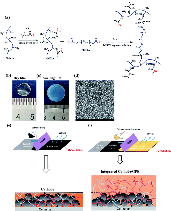
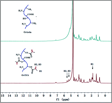
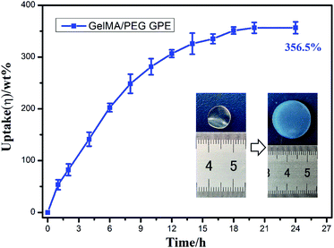
As showed in Fig. 1a, the gelatin was first modified by methacrylic anhydride via amidation and the reaction was characterized by 1H-NMR in Fig. 2. The hydrogen atoms of methacrylamide (H1, H2 and H3) were carefully labeled in the 1H-NMR spectrum. It's obvious to observe that the chemical shifts at 5.3 and 5.5 ppm are assigned to the H2 and H3 (the hydrogen atoms at the carbon–carbon double bond), respectively. And the chemical shift at 1.78 ppm demonstrated the hydrogen atoms H1 of methyl. The spectra clearly displayed that methacrylic groups were successfully grafted on the backbone of gelatin.Then, the crosslinked structure of GelMA/PEGDA (GP) was formed through the UV initiation. The crosslinked film GP was compared with gelatin (G) to demonstrated the thermal stability. The Fig. S1† showed the TG curves of G and GP. It was obviously observed that the degradation temperature of GP (345 °C) was higher than that of G (285 °C). The crosslinking process improved the thermal resistance. The pictures of dry and gel state of GelMA/PEGDA film were displayed in Fig. 1b and c. The dry film was soaked into liquid electrolyte to evaluate the uptake capacity at room temperature. Fig. 3 exhibited the electrolyte uptake capacity of GelMA/PEGDA films at different immersing time. The results showed that the equilibrium swelling ratio could reach up to about 356.5% after immersing 24 hours. The surface morphology of film was also provided here in Fig. 1d. The fibrous network structure on the surface of the film was clearly observed and porous network structure played a key role in liquid electrolyte uptake.
The design scheme of integrated cathode-gel polymer electrolyte was showed in Fig. 1e and f. In brief, the cathode material mixed with GelMA/PEGDA precursor solution to get the cathode slurry and then coated on the current collector under UV radiation. Here, the GelMA/PEGDA precursor solution was utilized as the binder to adhere the LiFePO4 cathode particles which was already reported in our previous work.30 Subsequently, the GelMA/PEGDA precursor solution was blading on cathode layer to obtain the integrated cathode-GPE structure.
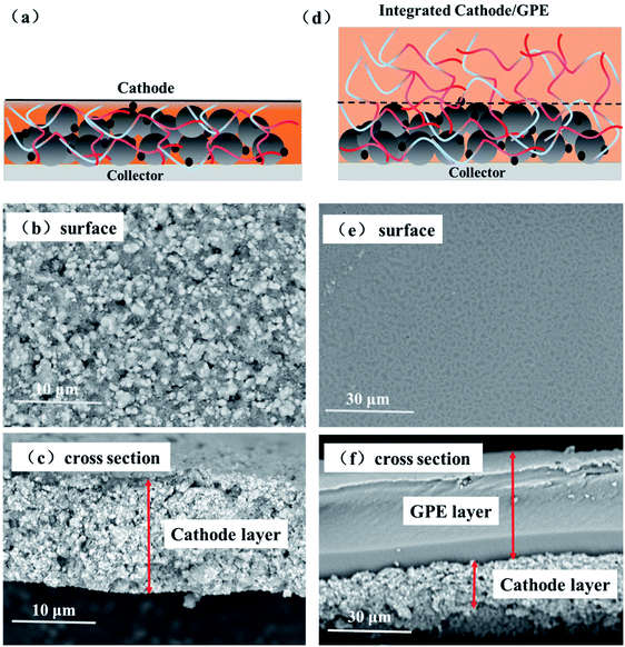
The surface and interface morphology images of cathode-GPE integrated cells were provided in Fig. 4. The surface and cross-section structure of cathode layer was provided here in Fig. 4b and c. It's obvious to find the rough surface and cross section of LiFePO4 particles. After blading the GPE precursor solution on the cathode layer (Fig. 4a), the integrated cathode-GPE structure was formed via UV curing (Fig. 4d). The surface morphology and the cross section of cathode-GPE layer was demonstrated in Fig. 4e and f. The surface became smooth because LiFePO4 particles were coated with a GPE layer. There was no gap was observed between cathode and GPE layer and the interface structure was intimate and void-free. This compact interface structure could be ascribed to two reasons. Firstly, the GelMA/PEGDA precursor solution could gradually infiltrate into the pores of cathode during the solidification process.26 Secondly, the compositional compatibility between GPE layer and cathode layer was another important factor to improve the interface contact. The thickness of cathode layer was about 15–20 μm and the thickness of GPE layer was about 30–40 μm. The thin film of GPE was beneficial for the penetrating of liquid electrolytes and the transporting of lithium ions.
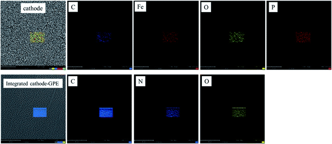
In order to analyze the difference of each layer clearly, the EDX mapping of cathode (LiFePO4) and integrated cathode-GPE were provided in Fig. 5. From the result showed below, it could be found that the element Fe and P in cathode was clear. But it was totally covered up after coating by GelMA/PEGDA film. By contrast, the element N in GelMA obviously appeared in integrated cathode-GPE. Therefore, it further verified the difference of each layer and guaranteed the success of integration design.
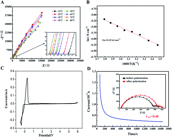
The electrochemical performances of gel polymer electrolyte (GPE) was carefully characterized in Fig. S2† and 6. Firstly, the interfacial compatibility between GPE and lithium metal sheet was characterized in Fig. S2.† Due the formation of passivation layer at the interface, the impedance of Li//GPE//Li cell was gradually increased from about 580 Ω to 900 Ω. The interface resistance of GPE was satisfactory to meet the requirements of cell coins. Then, temperature dependence of ionic conductivity for GPE sample was tested and shown in Fig. 6A and B. It can be seen that along with the increase of the temperature, ionic conductivity of GPE film increased gradually. This could be ascribe to the faster motion of polymer chains at higher temperature to promote faster migration of lithium ions. Based on the eqn (2) above, the ionic conductivity of GPE film at 25 °C could reach up to 2.32 × 10⁻³ S cm−1. When the temperature increased to 85 °C, the ionic conductivity could increase to 5.63 × 10⁻³ S cm−1 showed in Table S1,† which was relatively higher than other reported GPE films.31–33 The high ionic conductivity of GPE was attributed to the high uptake of liquid electrolyte and the ether linkages in the PEG chains which coordinated with lithium ions to facilitate the ions transport.34 In Fig. 6C, the electrochemical stability window of GelMA/PEGDA GPE film was exhibited by the linear sweep voltammetry. The cell assembled with GelMA/PEGDA GPE film was shown to have stable currents at a high voltage of 5.2 V. It meant that there was no appreciable decomposition of any components of GPE over a wider voltage range. The GelMA/PEGDA GPE films possessed better electrochemical stability even compared with the liquid electrolyte (no more than 4.5 V).35 Therefore, this kind of GelMA/PEGDA GPE films provided a promising alternative for high voltage LIBs. It's well known that a high lithium ion transference number could improve the rate and cycle stability, since the concentration gradient at the GPE surface and potential polarization could be avoid at a high Li+ transference number. In Fig. 6D, the Li+ transference number was calculated based on the eqn (3) above. We found that the GelMA/PEGDA GPE has a higher Li+ transference number of 0.48 than liquid electrolyte at room temperature. The high Li+ transference number was probably ascribed to the high liquid electrolyte uptake of GPE and the hydrogen-bond interaction between functional groups (e.g. –NH2 and –COOH) of GPE and anion part of lithium salts (TFSI−). The anion part of lithium salt was trapped in the network of GPE, which limited the transport the anion.36,37
The electrochemical properties of the GelMA/PEGDA gel film was carefully evaluated, and the results guaranteed the suitability of GelMA/PEGDA films as a gel polymer electrolyte. Then, the integrated and non-integrated cathode-GPE structure was designed to further investigate the interface compatibility and the cycle performances. In Fig. 7A and B, the impedance of non-integrated LiFePO4//GPE//Li cells and integrated LiFePO4-GPE//Li at first and 50th cycle respectively were tested to display the interface stability between GPE and LiFePO4 cathode. The single semicircle in high frequency region represented charge transfer resistance (Rct). As shown in Fig. 7A, the Rct of the non-integrated cell was about 1000 Ω at the first cycle and slightly decreased to 900 Ω at 50th cycle. However, the integrated cells in Fig. 7B displayed a much lower Rct of about 700 Ω compared with non-integrated cells, and the Rct decreased to about 600 Ω after 50th cycle. In addition, the intercept of x-axis in high frequency represents the bulk resistance of electrolyte (Rbulk). It is shown that the bulk resistance of the two cells were about 8.2 Ω that was negligible. The low interfacial impedance of integrated LiFePO4-GPE//Li cells could enable higher performance during cycling.
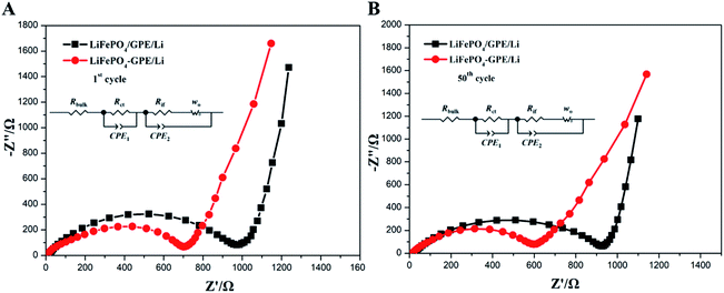 | ||
| Fig. 7 Nyquist plots of (A) non-integrated LiFePO4/GPE/Li and (B) integrated LiFePO4-GPE/Li coin cells at 0.2C. | ||
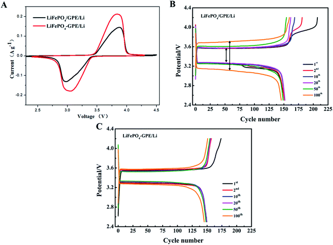
Furthermore, the electrochemical properties of the two kinds of cells (LiFePO4//GPE//Li and LiFePO4-GPE//Li) were compared to demonstrate the effect of integrated solidification method. Fig. 8A exhibited the CV curves of the two different assembled cells between 2.3 and 4.5 V (vs. Li/Li+) at a scan rate of 0.1 mV s−1 at room temperature. From the curves, it was found that LiFePO4//GPE//Li and LiFePO4-GPE//Li cells both exhibited obvious redox peaks. But the integrated LiFePO4-GPE//Li cells showed sharper anodic and cathodic peaks than that of non-integrated cells LiFePO4//GPE//Li. Meanwhile, the interval between oxidation peak and reduction peak in integrated cells were smaller than non-integrated cells. At the same time, curves of the charge and discharge voltage platforms at 0.2C at different cycles were shown in Fig. 8B. It could be found that the potential gap of non-integrated LiFePO4//GPE//Li cell was 0.30 V at first cycle. After 100 cycles, the potential gap increased to 0.54 V. In contrast, the potential gap of integrated LiFePO4-GPE//Li cell was 0.24 V at first cycle and there was no significant voltage interval increase after 100 cycles showed in Fig. 8C. It demonstrated that the cells prepared by integrated method exhibited stable potential plateaus, which strongly decrease the polarization effect during the repeated charging and discharging processes. Therefore, the integrated construction of GPE-cathode could not only efficiently improve the interfacial contact, but also improved the cycle stability and reversibility solid-state batteries.
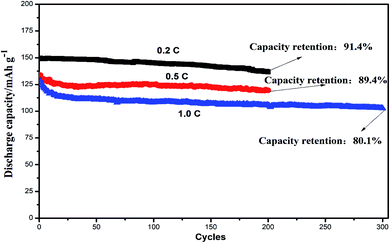
Fig. 9 showed the cycling performances of two different assembled batteries. The discharge capacity of integrated LiFePO4-GPE//Li cell was 136.7 mA h g−1 and had a high capacity retention of 91.4% after 200 cycles at 0.2C. In contrast, the discharge capacity of LiFePO4//GPE//Li maintained only at 122.1 mA h g−1 after 200 cycles and the capacity retention was only 80.9%, which were both lower than that of the integrated cells. Moreover, the coulombic efficiency of integrated LiFePO4-GPE//Li cell maintained above 95.2%, which was much higher than that of non-integrated cells (only 81.2%). It could be found that the coulombic efficiency of LiFePO4//GPE//Li cell gradually decreased starting from the 100th cycle, which was consistent with the results of potential polarization in the Fig. 8B. Therefore, the good interfacial contact and low potential polarization of LiFePO4-GPE//Li cell endowed the good cycling stability. Meanwhile, the rate property of the non-integrated and integrated cells was also compared in Fig. S3.† It demonstrated that there was no significant difference at the discharge capacity within the two kinds of cells at 0.2C. But at the high rate of 0.5C and 1C, the integrated cells maintained higher discharge capacity than the non-integrated cells. Furthermore, the long cycle performance of integrated cells at high rate were also evaluated in Fig. 10. It could be seen that the discharge capacity of cell at 0.5C was 119.5 mA h g−1 after 200 cycles. And the capacity retention was 89.4%. It maintained a high capacity of 102.7 mA h g−1 with a good retention of 80.1% at 1C even after 300 cycles. It could be concluded that the integrated cathode-GPE structure based on crosslinked GelMA/PEGDA gel possessed superior long cycling and rate performances compared with other reported gel polymer electrolytes.31,33,38–40 It meant that the continuous composition and fabrication method design was a prospective strategy to get integrated cathode-GPE lithium ion batteries with lower interface impedance, faster charge transfer, lower polarization and more stable cycling property.
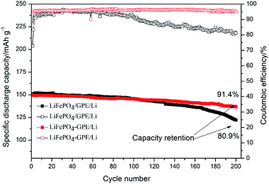 | ||
| Fig. 9 Cycling performance of the non-integrated cathode/GPE/Li and integrated cathode-GPE/Li coin cells at 0.2C. | ||
4 Conclusion
As a conclusion, a crosslinked polymer network GelMA/PEGDA was utilized both as the cathode binder and polymer electrolyte by simply UV solidification method. Because of the continuous composition and crosslinked network in the integrated cathode-GPE, the interfacial contact was dramatically improved and the charge transfer at the interface was faster than the non-integrated structure. And the assemble coin cells based on integrated LiFePO4 cathode-GPE displayed lower interfacial impedance, smaller polarization and excellent cycling stability.Conflicts of interest
There are no conflicts to declare.Acknowledgements
This work was financially support by National Science Foundation of China (Grant No. 21965012), Basic and Applying Basic Research Project of Hainan Province for High-level Talent (Grant No. 2019RC038), the Hainan Provincial Natural Science Foundation of China (2018CXTD332 and HD-SYSZX-201802), Science and Technology Development Special Fund Project (ZY2019HN09), and the Key Project of Jiangxi Natural Science Foundation (2020ACBL214008).References
- J. B. Goodenough and Y. Kim, Chem. Mater., 2010, 22, 587–603 CrossRef CAS.
- J. B. Goodenough and K.-S. Park, J. Am. Chem. Soc., 2013, 135, 1167–1176 CrossRef CAS.
- E. M. Erickson, C. Ghanty and D. Aurbach, J. Phys. Chem. Lett., 2014, 5, 3313–3324 CrossRef CAS.
- K. M. Abraham, J. Phys. Chem. Lett., 2015, 6, 830–844 CrossRef CAS.
- W. H. Meyer, Adv. Mater., 1998, 10, 439–448 CrossRef CAS.
- J. Y. Song, Y. Y. Wang and C. C. Wan, J. Power Sources, 1999, 77, 183–197 CrossRef CAS.
- A. M. Stephan, Eur. Polym. J., 2006, 42, 21–42 CrossRef.
- T. Dong, J. Zhang, G. Xu, J. Chai, H. Du, L. Wang, H. Wen, X. Zang, A. Du, Q. Jia, X. Zhou and G. Cui, Energy Environ. Sci., 2018, 11, 1197–1203 RSC.
- P.-L. Kuo, C.-A. Wu, C.-Y. Lu, C.-H. Tsao, C.-H. Hsu and S.-S. Hou, ACS Appl. Mater. Interfaces, 2014, 6, 3156–3162 CrossRef CAS.
- D. Zhou, X. Mei and J. Ouyang, J. Phys. Chem. C, 2011, 115, 16688–16694 CrossRef CAS.
- D. Lin, W. Liu, Y. Liu, H. R. Lee, P.-C. Hsu, K. Liu and Y. Cui, Nano Lett., 2016, 16, 459–465 CrossRef CAS.
- Y. Kim, S. J. Kwon, H.-k. Jang, B. M. Jung, S. B. Lee and U. H. Choi, Chem. Mater., 2017, 29, 4401–4410 CrossRef CAS.
- H. Zhai, P. Xu, M. Ning, Q. Cheng, J. Mandal and Y. Yang, Nano Lett., 2017, 17, 3182–3187 CrossRef CAS.
- W. Liu, S. W. Lee, D. Lin, F. Shi, S. Wang, A. D. Sendek and Y. Cui, Nat. Energy, 2017, 2, 17035–17042 CrossRef CAS.
- X. Cheng, J. Pan, Y. Zhao, M. Liao and H. Peng, Adv. Energy Mater., 2018, 8, 1702184–1702200 CrossRef.
- D. Santhanagopalan, D. Qian, T. McGilvray, Z. Wang, F. Wang, F. Camino, J. Graetz, N. Dudney and Y. S. Meng, J. Phys. Chem. Lett., 2014, 5, 298–303 CrossRef CAS.
- G. P. Pandey, S. A. Klankowski, Y. Li, X. S. Sun, J. Wu, R. A. Rojeski and J. Li, ACS Appl. Mater. Interfaces, 2015, 7, 20909–20918 CrossRef CAS.
- R. Chen, W. Qu, X. Guo, L. Li and F. Wu, Mater. Horiz., 2016, 3, 487–516 RSC.
- Y.-G. Cho, C. Hwang, D. S. Cheong, Y. o. Kim and H. o. Song, Adv. Mater., 2019, 31, 1970144 CrossRef.
- J. Xu, Q. Xia, F. Chen, T. Liu, L. Li, X. Cheng, W. Lu and X. Wu, Electrochim. Acta, 2016, 191, 687–694 CrossRef CAS.
- C. Wang, Q. Sun, Y. Liu, Y. Zhao, X. Li, X. Lin, M. N. Banis, M. Li, W. Li, K. R. Adair, D. Wang, J. Liang, R. Li, L. Zhang, R. Yang, S. Lu and X. Sun, Nano Energy, 2018, 48, 35–43 CrossRef CAS.
- Z. Wei, S. Chen, J. Wang, Z. Wang, Z. Zhang, X. Yao, Y. Deng and X. Xu, J. Power Sources, 2018, 394, 57–66 CrossRef CAS.
- X. Chen, W. He, L.-X. Ding, S. Wang and H. Wang, Energy Environ. Sci., 2019, 12, 938–944 RSC.
- D. Zhou, Y.-B. He, Q. Cai, X. Qin, B. Li, H. Du, Q.-H. Yang and F. Kang, J. Mater. Chem. A, 2014, 2, 20059–20066 RSC.
- Q. Xiao, C. Deng, Q. Wang, Q. Zhang, Y. Yue and S. Ren, ACS Omega, 2019, 4, 95–103 CrossRef CAS.
- S. Z. Zhang, X. H. Xia, D. Xie, R. C. Xu, Y. J. Xu, Y. Xia, J. B. Wu, Z. J. Yao, X. L. Wang and J. P. Tu, J. Power Sources, 2019, 409, 31–37 CrossRef CAS.
- S.-H. Kim, K.-H. Choi, S.-J. Cho, S. Choi, S. Park and S.-Y. Lee, Nano Lett., 2015, 15, 5168–5177 CrossRef CAS.
- W. Zhou, S. Wang, Y. Li, S. Xin, A. Manthiram and J. B. Goodenough, J. Am. Chem. Soc., 2016, 138, 9385–9388 CrossRef CAS.
- A. I. Van Den Bulcke, B. Bogdanov, N. De Rooze, E. H. Schacht, M. Cornelissen and H. Berghmans, Biomacromolecules, 2000, 1, 31–38 CrossRef CAS.
- L. Zhao, Z. Sun, H. Zhang, Y. Li, Y. Mo, F. Yu and Y. Chen, RSC Adv., 2020, 10, 29362–29372 RSC.
- D. Xu, J. Jin, C. Chen and Z. Wen, ACS Appl. Mater. Interfaces, 2018, 10, 38526–38537 CrossRef CAS.
- M. Y. Zhang, M. X. Li, Z. Chang, Y. F. Wang, J. Gao, Y. S. Zhu, Y. P. Wu and W. Huang, Electrochim. Acta, 2017, 245, 752–759 CrossRef CAS.
- J. Wan, J. Zhang, J. Yu and J. Zhang, ACS Appl. Mater. Interfaces, 2017, 9, 24591–24599 CrossRef CAS.
- Q. Lu, L. Dong, L. Chen, J. Fu, L. Shi, M. Li, X. Zeng, H. Lei and F. Zheng, Chem. Eng. J., 2020, 393, 124708 CrossRef CAS.
- G. Xu, P. Han, X. Wang, X. Zhou, X. Han, D. Lu, H. Liu, J. Zhao, J. Ma and G. Cui, ACS Appl. Mater. Interfaces, 2020, 12, 9468–9477 CrossRef CAS.
- K. Deng, Q. Zeng, D. Wang, Z. Liu, Z. Qiu, Y. Zhang, M. Xiao and Y. Meng, J. Mater. Chem. A, 2020, 8, 1557–1577 RSC.
- D. M. Shin, J. E. Bachman, M. K. Taylor, J. Kamcev, J. G. Park, M. E. Ziebel, E. Velasquez, N. N. Jarenwattananon, G. K. Sethi, Y. Cui and J. R. Long, Adv. Mater., 2020, 32, e1905771 CrossRef.
- T. C. Nirmale, I. Karbhal, R. S. Kalubarme, M. V. Shelke, A. J. Varma and B. B. Kale, ACS Appl. Mater. Interfaces, 2017, 9, 34773–34782 CrossRef CAS.
- D. Xu, B. Wang, Q. Wang, S. Gu, W. Li, J. Jin, C. Chen and Z. Wen, ACS Appl. Mater. Interfaces, 2018, 10, 17809–17819 CrossRef CAS.
- S. Wang, L. Zhang, Q. Zeng, X. Liu, W.-Y. Lai and L. Zhang, ACS Sustainable Chem. Eng., 2020, 8, 3200–3207 CrossRef CAS.
Footnotes |
| † Electronic supplementary information (ESI) available. See DOI: 10.1039/d0ra10743c |
| ‡ Feng Yu and Lingzhu Zhao make an equal contribution to this paper. |
| This journal is © The Royal Society of Chemistry 2021 |

