 Open Access Article
Solvent-assisted strongly enhanced light-emitting electrochemiluminescent devices for lighting applications
Joo Yeon Kim *ab,
Sanghoon Cheona,
Dae Kyom Kimc,
Sooji Nam
 d,
Jisu Han
 b,
Chi-Sun Hwanga,
Yuanzhe Piao
 ce and
Jeong-Ik Leef
aReality Display Research Lab., Reality Device Research Division, Electronics and Telecommunications Research Institute (ETRI), 34129 Daejeon, Korea. E-mail: jooyeon.kim@etri.re.kr; Fax: +82-42-860-6216; Tel: +82-42-860-6216
bICT-Advanced Device Technology, University of Science and Technology, 217 Gajeong-ro, Yuseong-gu, Daejeon 34113, Republic of Korea
cProgram in Nano Science and Technology, Graduate School of Convergence Science and Technology, Seoul National University, 16229 Suwon-si, Gyeonggi-do, Korea
dFlexible Electronic Device Research Lab., Electronics and Telecommunications Research Institute (ETRI), 34129 Daejeon, Korea
eAdvanced Institutes of Convergence Technology, Seoul National University, 16229 Suwon-si, Gyeonggi-do, Korea
fReality Device Research Division, Electronics and Telecommunications Research Institute (ETRI), 34129 Daejeon, Korea
First published on 25th January 2021
Abstract
Rubrene-based electrochemiluminescence (r-ECL) cells with two different solvent systems is prepared, one in a co-solvent system with a mixture of 1,2-dichlorobenzene and propylene carbonate (DCB![[thin space (1/6-em)]](https://www.rsc.org/images/entities/char_2009.gif) :
:![[thin space (1/6-em)]](https://www.rsc.org/images/entities/char_2009.gif) PC, v/v 3
PC, v/v 3![[thin space (1/6-em)]](https://www.rsc.org/images/entities/char_2009.gif) :
:![[thin space (1/6-em)]](https://www.rsc.org/images/entities/char_2009.gif) 1) and another in a single solvent system of tetrahydrofuran (THF), as the medium to form a liquid-electrolyte (L-El). By simply changing the solvent systems, from the co-solvent DCB
1) and another in a single solvent system of tetrahydrofuran (THF), as the medium to form a liquid-electrolyte (L-El). By simply changing the solvent systems, from the co-solvent DCB![[thin space (1/6-em)]](https://www.rsc.org/images/entities/char_2009.gif) :
:![[thin space (1/6-em)]](https://www.rsc.org/images/entities/char_2009.gif) PC (v/v 3
PC (v/v 3![[thin space (1/6-em)]](https://www.rsc.org/images/entities/char_2009.gif) :
:![[thin space (1/6-em)]](https://www.rsc.org/images/entities/char_2009.gif) 1) to the single solvent THF, with the same amount of electrochemiluminescent rubrene (5 mM) and Li-based salt, a dramatically enhanced brightness of over 30 cd m−2 is observed for the r-ECL cell in L-ElTHF which is approximately 7-times higher than the brightness of 5 cd m−2 observed for the r-ECL in L-ElDCB:PC(v/v 3:1).
1) to the single solvent THF, with the same amount of electrochemiluminescent rubrene (5 mM) and Li-based salt, a dramatically enhanced brightness of over 30 cd m−2 is observed for the r-ECL cell in L-ElTHF which is approximately 7-times higher than the brightness of 5 cd m−2 observed for the r-ECL in L-ElDCB:PC(v/v 3:1).
1. Introduction
Low-cost, thin, and lightweight devices such as inorganic light-emitting diodes (LEDs) and organic lighting-emitting diodes (OLEDs) are highly popular today because of their emissive lighting applications.1,2 However, both LEDs and OLEDs have remaining challenges, especially with their processability, because they require multiple fabrication steps involving vacuum evaporation processes, which result in high production costs affecting their wide-spreading range of applications. For example, fabrication requires the deposition of several layers, such as n-type and p-type diffusion layers in LEDs, and hole, electron, and emissive layers in OLEDs.3–5 As a result, there is significant interest in new light-emitting devices that could be adopted as alternatives to LEDs and/or OLEDs, which have simple device structures and can potentially be fabricated without any vacuum process, resulting in simpler processability as well as lower production cost.6 To achieve these requirements, other types of light-emitting devices can be suggested. One promising approach is the electrochemiluminescence (ECL)-based light-emitting device. An ECL device usually consists of an electrochemiluminescent material and electrolytes dissolved in a liquid or solid medium, placed between a fixed gap, sandwiched between two electrodes, allowing an electrochemical reaction to occur near the electrode surface.7–9 To be able to emit visible light, the electrochemiluminescent materials are reversibly oxidized and reduced in supporting electrolyte systems under an applied direct current (DC) and/or alternating current (AC) at a certain frequency.10–12 Compared to LEDs and OLEDs, ECL devices have a very simple structure which can effectively reduce processing costs. In our previous paper, four different ECL materials producing red, yellow, green and blue visible light were reported and demonstrated for potential lighting application. Among these four different ECL materials, rubrene, which is the ECL material emitting yellow light, showed the highest luminance of 12 cd m−2 in a square-wave AC bias voltage, and exhibited reversible redox-reaction during operation.13–17 However, its low luminance was a limitation to be improved. In its present composition, rubrene has low solubility into the co-solvent system DCB![[thin space (1/6-em)]](https://www.rsc.org/images/entities/char_2009.gif) :
:![[thin space (1/6-em)]](https://www.rsc.org/images/entities/char_2009.gif) PC (v/v 3
PC (v/v 3![[thin space (1/6-em)]](https://www.rsc.org/images/entities/char_2009.gif) :
:![[thin space (1/6-em)]](https://www.rsc.org/images/entities/char_2009.gif) 1). To address this, in this work, rather than using a co-solvent system, the ECL performance of a single solvent-assisted rubrene material was investigated.18 The intensity of the single solvent-assisted ECL dramatically increased, by approximately 7-times, and this is the first quantitatively reported value of this scale.
1). To address this, in this work, rather than using a co-solvent system, the ECL performance of a single solvent-assisted rubrene material was investigated.18 The intensity of the single solvent-assisted ECL dramatically increased, by approximately 7-times, and this is the first quantitatively reported value of this scale.
2. Results and discussion
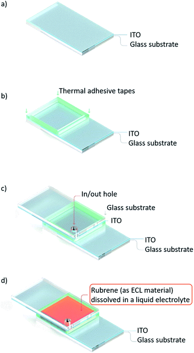
The schematic of the overall process flow for preparing the emitting ECL cell is illustrated in Fig. 1. In the first step, an ITO glass substrate with an active area of 1.0 × 1.0 cm2 was cleaned (Fig. 1a). A 100 μm-thick thermal adhesive tape was placed between face-to-face ITO glass substrates in order to bond them tightly by thermal treatment. In and out holes were punched in the upper ITO side (Fig. 1b and c). Finally, two rubrene-based ECL solutions, one containing liquid electrolyte (r-ECL L-El) dissolved in a co-solvent system of DCB and PC (v/v 3![[thin space (1/6-em)]](https://www.rsc.org/images/entities/char_2009.gif) :
:![[thin space (1/6-em)]](https://www.rsc.org/images/entities/char_2009.gif) 1) and one with a single solvent system of THF, were injected into two prepared ECL cells through the in/out hole (Fig. 1d).
1) and one with a single solvent system of THF, were injected into two prepared ECL cells through the in/out hole (Fig. 1d).
The operation of the prepared ECL cell is described in Fig. 2, which also shows the yellow visible light emission mechanism of the rubrene molecules.5–7,19,20 The ECL material, here designated R, indicates rubrene which mainly consists of C (carbon) and H (hydrogen). When the square-wave AC voltage is applied between the two electrodes of the ECL cell, it forms reversible oxidation state on the cathode (R˙+) and reduction state on the anode (R˙−) due to electrochemical redox reactions. When a collision occurs between the reduced and oxidized ECL materials at the near electrode surface, they are recombined, resulting in the forming of both annihilation and excitation states (R and *R). This excited state leads to the emission of yellow visible light (*R → R + hν) when the excited state falls to the ground state.
 | ||
| Fig. 2 Illustrated description of the prepared r-ECL L-El cell structure, and ECL mechanism which occurs due to the electrochemical redox reaction under the applied square-wave AC voltage. | ||
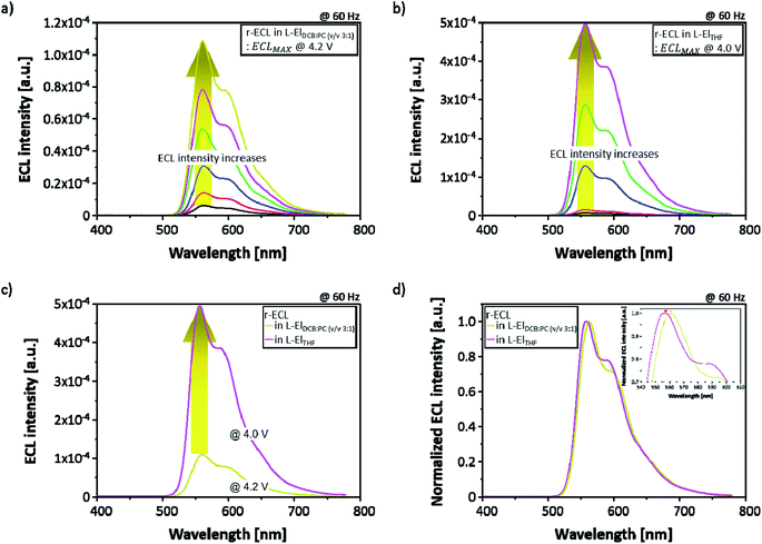
In order to compare the ECL performance of the two solvent systems, two different types of 5 mM rubrene-based ECL cell (r-ECL) were prepared. One was prepared with a liquid electrolyte-based co-solvent system (referred to as L-ElDCB:PC(v/v 3:1)) and another one was prepared with a single solvent system (referred to as L-ElTHF). Then, r-ECL spectra and current density–voltage characteristics were measured as a function of applied square-wave AC voltages ranging from 0 V to 5.0 V at a fixed frequency of 60 Hz. As presented in Fig. 3a and b, the r-ECL spectra form the two different solvent systems of L-ElDCB:PC(v/v 3:1) and L-ElTHF show a strong dependence on the applied square-wave AC voltages, resulting in significantly increased ECL intensities. The maximum ECL intensity around 560 nm wavelength with the second peak around 600 nm wavelength was obtained at 4.2 V for r-ECL in L-ElDCB:PC(v/v 3:1) and 4.0 V for r-ECL in L-ElTHF. Moreover, when the maximum r-ECL intensity in L-ElTHF was compared to L-ElDCB:PC(v/v 3:1), the r-ECL in L-ElTHF was dramatically enhanced, by approximately 5-times even applied at a slightly lower voltage (Fig. 3c). In addition, when the normalized ECL spectra of the maximized ECL intensity (Fig. 3d) were compared, the main peak of r-ECL spectrum in L-ElTHF was slightly blue-shifted, by around 6 nm from the 561 nm wavelength to 556 nm, and the second peak of it was slightly increased showing little dependence on solvent which is well known as vibronic-band peak coming from normal-motions related with atoms on the aromatic backbone. From the measured normalized-spectra comparison, it was demonstrated that the both phenomena did not affecting the visible color.21
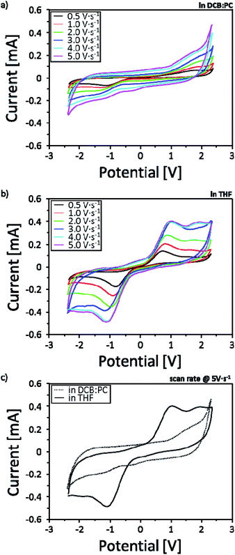
In order to investigate the solvent effect showing different ECL intensities based on the two-different solvent systems, reduction–oxidation (redox) behaviors were measured by potentiostatic cyclic voltammetry (CV) in the potential range of −2.4 V to +2.4 V with various scan rates of 0.5, 1.0, 2.0, 3.0, 4.0 and 5.0 V s−1 (Fig. 4). To reflect the effectiveness of the solvent effect into real r-ECL cells, two-electrode system is introduced for the CV measurement. In this case, one electrode is referred to as working electrode and the other electrode is referred to as (counter + reference) electrode. As evident from the CVs, r-ECL cells both in L-ElDCB:PC(v/v 3:1) and r-ECL in L-ElTHF showed increased current density with the increases in scan rates affecting to the diffusion kinetics. Although, both systems reveal the reversible redox reaction, it is difficult to observe distinguishable clear redox reactions for the for r-ECL in L-ElDCB:PC(v/v 3:1), which is ascribed to a weak redox reactivity in solution (Fig. 4a). However, r-ECL cells in L-ElTHF showed clear redox peaks indicating effectively generating rubrene radical cation (R˙+) and radical anion (R˙−) which is attributed to the formation of both annihilation and excitation states (R and *R), resulting in the light emission from the excited rubrene species (Fig. 4b). By the comparison of the each CV of r-ECL cells measured at a scan rate of 5.0 V s−1 (Fig. 4c), the strong redox peak both in −1 V and +1 V is observed in L-ElTHF. Therefore, this result indicates the THF based solvent system is dramatically enhanced the ECL intensity because it effectively generating redox species enhancing the redox reaction.
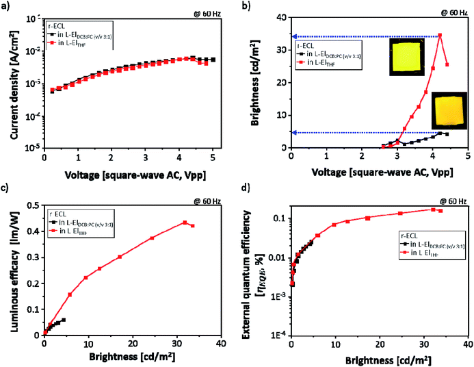
With the same r-ECL cells, the current density (mA cm−2) was also measured for the r-ECL in both L-ElDCB:PC(v/v 3:1) and in L-ElTHF during r-ECL spectra recording, and the brightness of the yellow emission from the r-ECL cell was evaluated using the known brightness (cd m−2) value for lighting applications under continuously applied square-wave AC voltages up to 5.0 V at a fixed frequency of 60 Hz. As shown in Fig. 5a, interestingly, a constant current behavior is observed, and there are no differences between the two systems, for the r-ECL cells prepared in L-ElDCB:PC(v/v 3:1) and in L-ElTHF. This demonstrates that similar amount of redox species are generated and are involved in the redox reaction for both. However, the measured brightness did show different behaviours. Fig. 5b shows the voltage-dependent brightness of both r-ECL in L-ElDCB:PC(v/v 3:1) and L-ElTHF. The emitted yellow colours indicate strongly enhanced brightness in the applied voltage ranges, especially for the prepared r-ECL in L-ElTHF. The voltage turn-on is 2.4 V, and the brightness increases continuously until reaching around 4.0 V. Although the corresponding turn-on voltages to get maximum brightness for both systems were recorded to be around 4.0 V, the r-ECL in L-ElTHF exhibited dramatically enhanced brightness of over 30 cd m−2, which was approximately 7-times higher than the brightness of 5 cd m−2 for the r-ECL in L-ElDCB:PC(v/v 3:1). However, when the square-wave AC voltage was more than 4.0 V, the r-ECL intensities dramatically decreased, affected by the loss of electroactive substance, rubrene, resulting from the reduced stability of the redox reaction.22
In order to correlate the luminous efficacy (LE, lm W−1) and external quantum efficiency (ηEQE, %), LE and ηEQE were calculated and plotted versus brightness (cd m−2) of two different solvent r-ECL systems both in L-ElDCB:PC(v/v 3:1) and in L-ElTHF. As seen in Fig. 5c, the LE value of r-ECL in L-ElTHF was dramatically enhanced approximately 10-times higher than in L-ElDCB:PC(v/v 3:1). Moreover, the similar behavior has also displayed in the ηEQE value with the around 8 times increases in L-ElTHF, which can also be affected by the dissociation effect.
3. Conclusion
The influence of such solvent effect on electrochemiluminescence (ECL) cell performance was investigated. ECL cells were prepared in two different solvent systems, one in a co-solvent system with a mixture of 1,2-dichlorobenzene and propylene carbonate (DCB![[thin space (1/6-em)]](https://www.rsc.org/images/entities/char_2009.gif) :
:![[thin space (1/6-em)]](https://www.rsc.org/images/entities/char_2009.gif) PC, v/v 3
PC, v/v 3![[thin space (1/6-em)]](https://www.rsc.org/images/entities/char_2009.gif) :
:![[thin space (1/6-em)]](https://www.rsc.org/images/entities/char_2009.gif) 1), and another one in a single solvent system of tetrahydrofuran (THF). When the ECL performances were compared, dramatically enhanced brightness, approximately 7-times more, was achieved by simply changing the solvent system from the co-solvent of DCB
1), and another one in a single solvent system of tetrahydrofuran (THF). When the ECL performances were compared, dramatically enhanced brightness, approximately 7-times more, was achieved by simply changing the solvent system from the co-solvent of DCB![[thin space (1/6-em)]](https://www.rsc.org/images/entities/char_2009.gif) :
:![[thin space (1/6-em)]](https://www.rsc.org/images/entities/char_2009.gif) PC (v/v 3
PC (v/v 3![[thin space (1/6-em)]](https://www.rsc.org/images/entities/char_2009.gif) :
:![[thin space (1/6-em)]](https://www.rsc.org/images/entities/char_2009.gif) 1) to the single solvent of THF indicating the reactivity of the generated redox species was affected by the solvent systems. Although the brightness still needs improvement, considering the simple device system and easy enhancement of brightness, the ECL device can be used as alternative to OLEDs for lighting applications.
1) to the single solvent of THF indicating the reactivity of the generated redox species was affected by the solvent systems. Although the brightness still needs improvement, considering the simple device system and easy enhancement of brightness, the ECL device can be used as alternative to OLEDs for lighting applications.
4. Experimental section
4.1. Materials
For the ECL materials, sublimed graded 5,6,11,12-tetraphenylnaphthacene (rubrene) was purchased from Luminescence Technology Corp. (Taiwan) and used as received. 1,2-Dichlorobenzene (DCB, 99.0% anhydrous), propylene carbonate (PC, 99.7% anhydrous), tetrahydrofuran (THF, 99.9% anhydrous), tetrabutylammonium hexafluorophosphate (TBAPF6, 99.0%), and lithium trifluoromethanesulfonate (LiCF3SO3, 96.0%) were supplied by Sigma-Aldrich (USA) and used without further purification. Indium tin oxide (ITO)-deposited glass substrates with a sheet resistance (Rs) of 25 Ω sq−1 were used.4.2. Preparation of ECL lighting cell
The ECL cells were prepared using cleaned ITO glass substrates that were arranged with a sandwich-type configuration, face-to-face, and it were sealed using a 100 μm-thick thermal adhesive tape, in order to keep the gap constant and to prevent leaks of the rubrene-based ECL liquid electrolyte (r-ECL L-El) solution during device testing. r-ECL L-El solutions were prepared for a co-solvent system of DCB and PC (v/v 3![[thin space (1/6-em)]](https://www.rsc.org/images/entities/char_2009.gif) :
:![[thin space (1/6-em)]](https://www.rsc.org/images/entities/char_2009.gif) 1), and a single solvent system of THF. The r-ECL solution contained 5 mM of dissolved rubrene in order to emit ECL lighting, as well as 10 mM of dissolved LiCF3SO3 and 100 mM of TBAPF6 in order to generate the redox reaction in both solvent systems. Before injection into the ECL cell, all the prepared r-ECL solution were deoxygenated probably presenting in r-ECL solutions by nitrogen gas purging procedure. Then, the r-ECL L-El solution was injected into the prepared ECL cell, which was filled by capillary force. In order to compare the ECL performance quantitatively, the active area of the ECL cell was kept at 1.0 × 1.0 cm2. The final structure of the ECL cell simply prepared in ambient air was ITO//r-ECL L-El//ITO.
1), and a single solvent system of THF. The r-ECL solution contained 5 mM of dissolved rubrene in order to emit ECL lighting, as well as 10 mM of dissolved LiCF3SO3 and 100 mM of TBAPF6 in order to generate the redox reaction in both solvent systems. Before injection into the ECL cell, all the prepared r-ECL solution were deoxygenated probably presenting in r-ECL solutions by nitrogen gas purging procedure. Then, the r-ECL L-El solution was injected into the prepared ECL cell, which was filled by capillary force. In order to compare the ECL performance quantitatively, the active area of the ECL cell was kept at 1.0 × 1.0 cm2. The final structure of the ECL cell simply prepared in ambient air was ITO//r-ECL L-El//ITO.
4.3. Characterization
Electrochemistry measurements were performed with a potentiostat (CHI660E, CH Instrument Inc., USA). Potentiostatic cyclic voltammetry was conducted with a two-electrode system in which ITO (with an active area of about 1 cm × 1 cm) was used as a working and counter electrodes. The current–voltage–luminance (I–V–L) characteristics of the emitted light of the ECL cells were measured using a current–voltage source unit (Keithley 238, Keithley Instruments Inc., USA). The front side ECL spectra were recorded using a goniometer-equipped spectroradiometer (Konica Minolta CS-2000, Japan) as a function of alternatively applied AC voltage at a constant frequency of 60 Hz.Conflicts of interest
There are no conflicts to declare.Acknowledgements
This work was supported by Institute for Information & Communications Technology Promotion (IITP) grant funded by the Korea Government (MSIT) (B0101-16-0133, the core technology development of light and space adaptable energy-saving I/O platform for future advertising service).References
- V. C. Bender, T. B. Marchesan and J. M. Alonso, IEEE Ind. Electron. Mag., 2015, 9, 6–16 Search PubMed.
- A. Khazanchi, A. Kanwar, L. Saluha, A. Damara and V. Damara, Int. J. Eng. Comput. Sci., 2012, 1, 75–84 Search PubMed.
- N. Guan, X. Dai, A. V. Babichev, F. H. Julien and M. Tchernycheva, Chem. Sci., 2017, 8, 7904–7911 RSC.
- Y.-S. Tyan, J. Photonics Energy, 2011, 1, 011009 CrossRef.
- J. Y. Kim, C. W. Joo, J. Lee, J.-C. Woo, J.-Y. Oh, N. S. Baek, H. Y. Chu and J.-I. Lee, RSC Adv., 2015, 5, 8415–8421 RSC.
- T. Nobeshima, M. Nakakomi, K. Nakamura and N. Kobayashi, Adv. Opt. Mater., 2013, 1, 144–149 CrossRef.
- L. Hu and G. Xu, Chem. Soc. Rev., 2010, 39, 3275–3304 RSC.
- Z. Liu, W. Qi and G. Xu, Chem. Soc. Rev., 2015, 44, 3117–3142 RSC.
- R. J. Forster, P. Bertoncello and T. E. Keyes, Annu. Rev. Anal. Chem., 2009, 2, 359–385 CrossRef CAS.
- J. Li, S. Guo and E. Wang, RSC Adv., 2012, 2, 3579–3586 RSC.
- M. M. Richter, Chem. Rev., 2004, 104, 3003–3036 CrossRef CAS.
- A. J. Bard and M. Dekker, Electrogenerated Electrochemiluminescence, 2004 Search PubMed.
- J. Y. Kim, S. Cheon, H. Lee, J.-Y. Oh, J.-I. Lee, H. Ryu, Y.-H. Kim and C.-S. Hwang, J. Mater. Chem. C, 2017, 5, 4214–4218 RSC.
- R. Nishimura and E. Nihei, Jpn. J. Appl. Phys., 2016, 55, 042101 CrossRef.
- T. Nobeshima, K. Nakamura and N. Kobayashi, Jpn. J. Appl. Phys., 2013, 52, 05DC18 CrossRef.
- T. Daimon and E. Nihei, J. Mater. Chem. C, 2013, 1, 2826–2833 RSC.
- Q. Pei, G. Yu, C. Zhang, Y. Yang and A. J. Heeger, Science, 1995, 269, 1086–1088 CrossRef CAS.
- H. Tachikawa and A. J. Bard, Chem. Phys. Lett., 1974, 26, 246–251 CrossRef CAS.
- F. E. Beideman and D. M. Hercules, J. Phys. Chem., 1979, 83, 2203–2209 CrossRef CAS.
- N. E. Tokel and A. J. Bard, J. Am. Chem. Soc., 1972, 94, 2862–2863 CrossRef CAS.
- Y. Hu, C.-W. Wang, C. Zhu, F. Gu and S.-H. Lin, RSC Adv., 2017, 7, 12407–12418 RSC.
- D. Laser and A. J. Bard, J. Electrochem. Soc., 1975, 122, 632–640 CrossRef CAS.
| This journal is © The Royal Society of Chemistry 2021 |


