 Open Access Article
Enhanced high voltage performance of LiNi0.5Mn0.3Co0.2O2 cathode via the synergistic effect of LiPO2F2 and FEC in fluorinated electrolyte for lithium-ion batteries
Rui Lia,
Pan Zhanga,
Jian Huanga,
Boyu Liua,
Mingjiong Zhou *a,
Bizheng Wen*b,
Yu Luoc and
Shigeto Okadad
aSchool of Materials Science and Chemical Engineering, Ningbo University, Fenghua Road 818, Jiangbei District, Ningbo 315211, Zhejiang Province, People's Republic of China. E-mail: zhoumingjiong@nbu.edu.cn
bNingbo Procutivity Promotion Center, Yangfan Road 999, Hi-tech Zone, Ningbo 315100, Zhejiang Province, People's Republic of China
cNingbo Nanomicro Energy Technology Co., Ltd., Ningbo 315800, Zhejiang Province, People's Republic of China
dInstitute for Materials Chemistry and Engineering, Kyushu University, 6-1 Kasuga-koen, Kasuga 816-, 8580, Japan
First published on 18th February 2021
Abstract
LiNi0.5Mn0.3Co0.2O2 can achieve high energy density due to its merits of high theoretical capacity and a relatively high operating voltage, but the LiNi0.5Mn0.3Co0.2O2 battery suffers from capacity decay because of the unstable solid electrolyte interface on the cathode. Herein, we investigate the application of a fluorinated electrolyte composed of fluoroethylene carbonate (FEC) as a cosolvent and lithium difluorophosphate (LiPO2F2) as a salt-type additive extending the life span of the LiNi0.5Mn0.3Co0.2O2 cathode. LiNi0.5Mn0.3Co0.2O2 can achieve and maintain a capacity of 157.7 mA h g−1 over 200 cycles at a 1C rate between 3.0 and 4.4 V, as well as a reversible capacity of 132.7 mA h g−1 even at the high rate of 10C. The enhanced performance can be ascribed to the formation of the robust and protective fluorinated organic–inorganic film on the cathode, which derives from the FEC cosolvent and LiPO2F2 additive and ensures facile lithium-ion transport. The synergistic effect of the cosolvent and additive to boost the electrochemical performance of LiNi0.5Mn0.3Co0.2O2 cathode will pave a new pathway for high-voltage cathode materials.
1. Introduction
Lithium-ion batteries (LIBs) have been perceived as suitable power sources for portable electronic devices and have emerged remarkably in our daily lives.1 Cathode materials that operate at high voltages have been developed to increase the energy density of LIBs.2–4 However, the overcharged cathode also accelerates the decomposition of the electrolytes at high potential,5,6 resulting in the formation of an unstable solid electrolyte interphase (SEI) film composed of organic carbonate and inorganic lithium salts on the cathode surface.7,8 It is well known that the conventional organic electrolyte results in a poor and thick SEI layer, which contains a large number of the resistive decomposition products of LiF and Li2CO3,9 as well as other inorganic and organic by-products.10 To achieve the high energy density, LIBs are operated at high voltage accompanied by the decomposition of the electrolyte11–14 and the collapse of the structure of the electrode,13,15 which ultimately leads to poor electrochemical performance. Therefore, new electrolyte components, especially solvents and additives, must be developed to accommodate those high-potential applications.Recently, fluorinated SEI film generated by the decomposition of fluorinated solvents or anions was reported as a stable film that can regulate the diffusion behavior of lithium ions and extend the life of LIBs.16,17 A fluoroethylene carbonate (FEC) has been developed to effectively improve the electrochemical performances and change the nature of the SEI layer of electrodes in LIBs.18 Aurbach et al. demonstrated the excellent cycling stability of Li|Li symmetric cells and Li|NCM cells in the FEC-based electrolyte, because of the formation of a stable SEI on the electrode surface.19,20 Replacing EC with FEC in the electrolyte for high-voltage LIBs showed dramatically improved cycling behavior of LiCoPO4/Li cells due to the formation of an effective protective film on the cathode.21 Sun et al. reported that the prominent cycling stability and high coulombic efficiency under the high areal loading conditions of LiNi0.6Mn0.2Co0.2O2/Li batteries were achieved by combining traditional ethyl methyl carbonate (EMC) with FEC solvents.10 Cryo-electron microscopy as a powerful analytical technique was used to reveal the nanostructure of SEI influenced by FEC; unlike a mosaic film in an electrolyte without FEC, the SEI formed in the FEC-containing electrolyte was a multilayer nanostructure film.22,23
The resultant SEI interface generated from the organic film-forming electrolyte is less ionically conductive than those generated from the decomposition of inorganic salt. Lithium difluorophosphate (LiPO2F2) as a new salt-type additive has attracted a lot of attention and participated in the formation of a film on graphite with high ionic conductivity and stable surface to enhance the high rate performance of graphite electrodes.24,25 LiPO2F2 can also improve the performance of LIBs under high voltages due to a stable SEI film formed on the cathode surface.26–28 The stable SEI film can effectively prevent direct contact between the cathode material and the electrolyte, thus suppressing the detrimental interfacial reactions. Even though LiPO2F2 has been reported before, it is usually studied alone, or in combination with other additives. The cooperation of the organic cosolvent and inorganic additive in an electrolyte has multiple benefits that can play a synergistic role, neutralize their drawbacks and improve the comprehensive performance of LIBs. The resultant organic–inorganic SEI film derived from organic cosolvent and inorganic lithium salts exhibits high ionic conductivity, which not only decreases the interfacial resistance, it also enhances the stability of the electrode/electrolyte interface, resulting in the suppression of the oxidation of the electrolyte and the dissolution of transition metal ions. To the best of our knowledge, the effectiveness of LiPO2F2 in an EC-free FEC-based electrolyte has not been reported for high-voltage LIBs. In this work, LiPO2F2 as an additive was applied in 1 M LiPF6/FEC/DMC solution for LIBs. The electrochemical performance of the LiNi0.5Mn0.3Co0.2O2 cathode in a LiPO2F2-containing FEC-based electrolyte was investigated and the effect of the LiPO2F2-containing FEC-based electrolyte was clarified under high voltage.
2. Experimental
The EC-based electrolyte consists of 1.0 M LiPF6 in the solvent mixture of ethylene carbonate (EC) and dimethyl carbonate (DMC) (3![[thin space (1/6-em)]](https://www.rsc.org/images/entities/char_2009.gif) :
:![[thin space (1/6-em)]](https://www.rsc.org/images/entities/char_2009.gif) 7 by volume). The FEC-based electrolyte was prepared by dissolving 1.0 M LiPF6 in a solvent mixture of fluoroethylene carbonate (FEC) (98%, Macklin Co., Ltd.) and DMC (3
7 by volume). The FEC-based electrolyte was prepared by dissolving 1.0 M LiPF6 in a solvent mixture of fluoroethylene carbonate (FEC) (98%, Macklin Co., Ltd.) and DMC (3![[thin space (1/6-em)]](https://www.rsc.org/images/entities/char_2009.gif) :
:![[thin space (1/6-em)]](https://www.rsc.org/images/entities/char_2009.gif) 7 by volume) in the glove box filled with Ar gas. Hybrid electrolytes were prepared by the addition of 1 wt% LiPO2F2 (Ningbo Nanomicro Energy Technology Co., Ltd.) to the FEC-based electrolyte. The viscosities and conductivities of the electrolyte were measured by a DV-2T viscometer (Brookfield, USA) and FE38 standard conductivity meter (Mettler-Toledo, Switzerland) at temperatures ranging from 298 K to 338 K. The color changes and acidities of the samples before and after storage were monitored by photographs and pH paper (Sinopharm Chemical Reagent Co. Ltd.), respectively. The solvent molecules (EC, FEC and DMC), lithium salt (LiPF6) and additive (LiPO2F2) in the electrolyte were geometrically optimized and the relative energy calculated using the Gaussian 09 software. In addition, the B3LYP density functional theory with 6-311+G(d, p) basis set was used to calculate the highest unoccupied molecular orbital energy and the lowest unoccupied molecular orbital energy (EHOMO and ELUMO).
7 by volume) in the glove box filled with Ar gas. Hybrid electrolytes were prepared by the addition of 1 wt% LiPO2F2 (Ningbo Nanomicro Energy Technology Co., Ltd.) to the FEC-based electrolyte. The viscosities and conductivities of the electrolyte were measured by a DV-2T viscometer (Brookfield, USA) and FE38 standard conductivity meter (Mettler-Toledo, Switzerland) at temperatures ranging from 298 K to 338 K. The color changes and acidities of the samples before and after storage were monitored by photographs and pH paper (Sinopharm Chemical Reagent Co. Ltd.), respectively. The solvent molecules (EC, FEC and DMC), lithium salt (LiPF6) and additive (LiPO2F2) in the electrolyte were geometrically optimized and the relative energy calculated using the Gaussian 09 software. In addition, the B3LYP density functional theory with 6-311+G(d, p) basis set was used to calculate the highest unoccupied molecular orbital energy and the lowest unoccupied molecular orbital energy (EHOMO and ELUMO).
Slurries were prepared containing 80 wt% active materials, 10 wt% super P and 10 wt% PVdF in N-methyl-2-pyrrolidone. The slurries were coated onto aluminum foil and dried at 110 °C for 12 h in a vacuum oven, and then punched into 12 mm diameter disks for testing. The electrochemical properties were investigated using CR2032 coin-type half-cells, which were assembled in a glove-box filled with argon. A lithium-foil and a polypropylene film (Celgard 3501) were used as the counter electrode and separator, respectively. The galvanostatic charge/discharge tests were carried out at a constant current density between 3.0 and 4.4 V using a LAND battery system (Wuhan, China). The electrochemical window of electrolytes was studied by linear sweep voltammetry (LSV) between 3.0 and 6.0 V vs. Li/Li+ with a scan rate of 5 mV s−1. Cyclic voltammetry (CV) measurements were performed in the potential range of 3.0–4.4 V at a scan rate of 1 mV s−1. Electrochemical impedance spectroscopy (EIS) studies were conducted using an AC amplitude of 5 mV in a frequency range of 0.01–100 kHz. LSV, CV and EIS tests were collected by a CHI-660E workstation at 25 °C. LSV was taken on stainless steel/Li cells, while the LiNi0.5Mn0.3Co0.2O2/Li cells were used for CV and EIS tests.
To analyze the surface component and morphology of the LiNi0.5Mn0.3Co0.2O2 cathodes, the cells before and after cycling were disassembled in a glove box. The electrodes were soaked in DMC for 1 h to remove the residual electrolyte, and dried under vacuum at room temperature. The morphology of the electrodes was observed by scanning electron microscopy (SEM, Hitachi, Japan) and transmission electron microscopy (TEM, Tecnai F30, Netherlands). The chemical analysis of surface compositions was characterized by X-ray photoelectron spectroscopy (XPS, Thermo Scientific K-Alpha).
3. Results and discussion
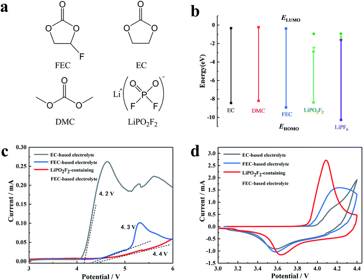
The chemical structure and molecular orbital energies of the electrolyte components, as well as the electrochemical stabilities of the electrolytes are shown in Fig. 1. Fig. 1a and b show the chemical structure of the electrolyte components, the highest occupied molecular orbital (HOMO) energies, and the lowest unoccupied molecular orbital (LUMO) energies, respectively. For the molecule with higher HOMO energy, the electron in the outermost layer has higher energy and tends to be lost more easily at high voltage, resulting in the oxidization of the molecule at a lower voltage. It was found that FEC has lower HOMO energy than other solvents (EC and DMC). Hence, the FEC replacing the EC as the cosolvent in the electrolyte can broaden the electrochemical window. For the molecule with a lower LUMO energy, the foreign electrons are more likely to occupy this orbital, and thus the molecule is reduced at a higher voltage. It can be seen that LiPO2F2 had a lower LUMO energy, reflecting stronger electron affinity.The electrochemical stabilities of the electrolytes were investigated by linear sweep voltammetry (LSV), as shown in Fig. 1c. The oxidation current of the cosolvent EC-based electrolyte appeared at around 4.1 V (vs. Li/Li+) and increased above 4.2 V (vs. Li/Li+), while the decomposition voltage of the FEC-based electrolyte was around 4.3 V (vs. Li/Li+). After the addition of LiPO2F2 to the FEC-based electrolyte, the starting oxidation potential of the FEC-based electrolyte increased to approximately 4.4 V (vs. Li/Li+). Furthermore, the oxidation current of the LiPO2F2-containing FEC-based electrolyte was relatively small and remained stable in the voltage range of 4.3–6.0 V, suggesting that the combination of the FEC cosolvent and the LiPO2F2 additive can increase the anodic limiting potential. Fig. 1d shows the CV curves of the first cycle of the LiNi0.5Mn0.3Co0.2O2 cathode in various electrolytes. A pair of oxidation/reduction peaks accompanied by Ni2+/Ni4+ and Co3+/Co4+ were observed during the Li+ extraction and insertion.29,30 Among them, the oxidation and reduction peaks of the FEC-based electrolyte containing LiPO2F2 were more obvious and the distance between these two peaks was closer. These results indicated that the FEC cosolvent and LiPO2F2 additive can significantly alleviate the electrochemical polarization, and the Li+ insertion/extraction process became much more reversible.
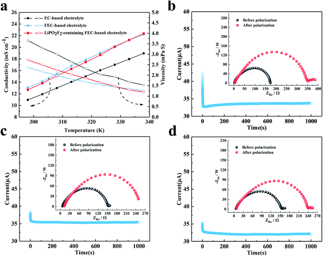
The conductivity and viscosity of the electrolyte play an important role in the performance of a battery. Fig. 2 shows the conductivity, viscosity and lithium-ion transference number of the electrolytes. As shown in Fig. 2a, the FEC-based electrolytes exhibited higher conductivity and lower viscosity than the EC-based electrolyte. However, the addition of 1 wt% LiPO2F2 to the FEC-based electrolyte resulted in a slight decrease in the conductivity and an increase in the viscosity, due to the dissociation energy of LiPO2F2 being higher than that of LiPF6. Fig. 2b–d show the dc polarization current responses, and the corresponding impedance spectra before and after the dc polarization of the Li/Li symmetric cells. The Li+ migrations were calculated according to eqn (1),31–35 and are summarized in Table 1:
 | (1) |
| Sample | I0 (μA) | ISS (μA) | R0 (Ω) | RSS (Ω) | ΔV (mV) | tLi+ |
|---|---|---|---|---|---|---|
| EC-based electrolyte | 42.32 | 33.56 | 173.9 | 358.8 | 10 | 0.48 |
| FEC-based electrolyte | 38.37 | 35.34 | 148.2 | 262.2 | 10 | 0.56 |
| LiPO2F2-containing FEC-based electrolyte | 35.32 | 32.03 | 150.1 | 240.2 | 10 | 0.62 |
Io and Is are the initial state and steady-state currents. Ro and Rs are the initial resistance and stable resistance of the passivation layer, respectively. ΔV is the voltage applied across the Li/Li cell. The EIS measurements of the symmetric cell were carried out before and after polarization, and an interval of an hour between the tests was needed to reach a quasi-equilibrium state. The polarization measurements were applied a 10 mV dc voltage to a symmetrical battery, and a stable current was obtained after 1000 s. The respective values of tLi+ for the EC-based electrolyte, FEC-based electrolyte and LiPO2F2-containing FEC-based electrolyte at 25 °C were 0.48, 0.56 and 0.62, respectively. It was demonstrated that the O2− electron cloud of LiPO2F2 had a strong attraction to Li+ and caused anion deformation due to the strong anion coordination effect.26 Hence, this effect enhanced the dissociation effect of the Li+ and PF6− ion-pair, and then made Li+ easier to move in the electrolyte, resulting in a high lithium-ion transference number (tLi+).36
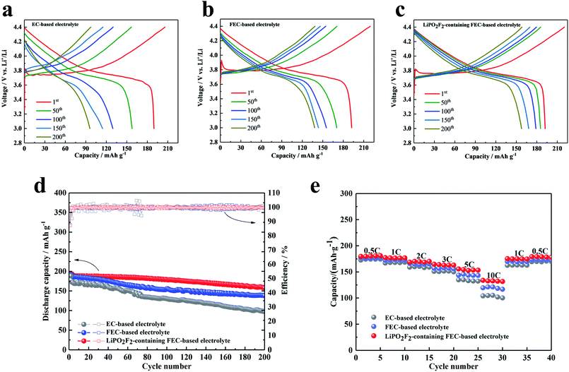
Fig. 3 shows the electrochemical properties of Li/LiNi0.5Mn0.3Co0.2O2 cells cycled in different electrolytes between 3.0 and 4.4 V at 1C rate (three activated cycles with 0.1C rate). Fig. 3a–c present the voltage profiles of the Li/LiNi0.5Mn0.3Co0.2O2 cell in various electrolytes for the 1st, 50th, 100th, 150th and 200th cycles, respectively. The initial charge and discharge capacities of the cell with the EC-based electrolyte were 205.9 mA h g−1 and 189.9 mA h g−1, respectively, which corresponded to an initial coulombic efficiency of 92.2%. The cell cycled in FEC-based electrolyte without additive exhibited a lower initial coulombic efficiency of 87.5% (discharge and charge capacities were 192.3 mA h g−1 and 219.6 mA h g−1, respectively). Similar to the FEC-based electrolyte, the cell cycled with the LiPO2F2-containing FEC-based electrolyte also showed a coulombic efficiency of 87.2%. This low initial coulombic efficiency was attributed to the electrolyte decomposition with the formation of the SEI film on the cathode. After the second cycle, the charge and discharge process proceeded reversibly, although the capacity generally decreased for all samples. Fig. 3d compares the cyclic stability of batteries with various electrolytes at 1C rate (three activated cycles with 0.1C rate). It can be seen that the cells in the FEC-based electrolyte showed better cyclic stability than that in the EC-based electrolyte, due to a more stable SEI film formed in the FEC-based electrolyte.19 Furthermore, with the addition of LiPO2F2 in the FEC-based electrolyte, the cyclic stability was remarkably improved, and the capacity decreased from 192.2 mA h g−1 to 157.7 mA h g−1 for up to 200 cycles, corresponding to a capacity retention of 82.1%. This phenomenon can be attributed to an excellent film on the cathode surface modified by the LiPO2F2, which can suppress the further decomposition of the solvents, resulting in enhanced interfacial stability of the cathode/electrolyte and the cyclic stability of the LiNi0.5Mn0.3Co0.2O2 cathode.26–28
The rate capability of the LiNi0.5Mn0.3Co0.2O2 cells with various electrolytes was also compared. Fig. 3e shows the specific capacities of the LiNi0.5Mn0.3Co0.2O2 cathode at current densities of 0.5C, 1C, 2C, 3C, 5C, and 10C (1C = 170 mA h g−1) in the voltage range of 3.0–4.4 V. Because of the higher lithium-ion transference number, the FEC-based electrolytes exhibited a better rate performance than the EC-based electrolyte. Moreover, the battery with the LiPO2F2-containing FEC-based electrolyte can reach a specific capacity of 132.7 mA h g−1, even at the high rate of 10C. This observation added evidence for the extremely stable SEI film formed on the cathode surface with high ionic conductivity, accompanied by the electrochemical decomposition of the FEC cosolvent and LiPO2F2 additive.
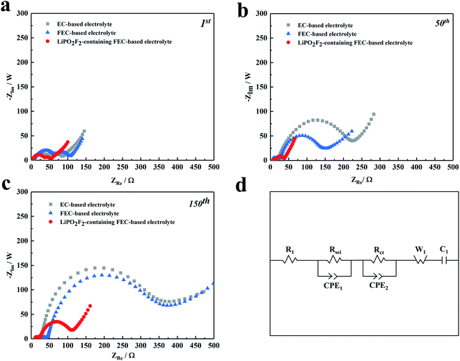
The synergistic effectiveness of LiPO2F2 and FEC in the fluorinated electrolyte on the performance of LiNi0.5Mn0.3Co0.2O2 cells was further investigated by EIS measurements. Fig. 4 shows Nyquist plots for the LiNi0.5Mn0.3Co0.2O2 cells before and after 1, 50, and 150 cycles, respectively, together with the corresponding equivalent circuit model. The values of interface resistance and electrolyte resistance estimated from the impedance spectra are illustrated in Table 2. All the EIS spectra consist of two semicircles in the high-medium frequency region and a sloped line in the low-frequency region. The high-frequency semicircle is associated with the electrode surface film resistance (Rsei), while the mid-frequency semicircle represents the charge transfer resistance (Rct) between the electrodes. The straight line in the low-frequency region is ascribed to the Warburg impedance (W1, relating to Li+ diffusion within the electrode).37–39 It was noted that the semicircles of samples increased continuously with cycling at high-medium frequency, which was ascribed to the progressive growth of SEI on the cathode surface and the increased thickness of the SEI film caused by the electrolyte decomposition. Both resistances, Rsei and Rct, increased from the 1st to the 150th cycle in the following order: LiPO2F2-containing FEC-based electrolyte < FEC-based electrolyte < EC-based electrolyte. It was implied that the surface film formed on the cathode in the EC-based solution was thicker than that in the FEC-based solution. The replacement of EC by FEC could change the composition of the SEI film, making it easier for Li+ to pass through the interface layer.19 More importantly, the increase in Rct slowed down significantly with cycling for cells after the addition of LiPO2F2 in the electrolyte, which confirmed that a relatively stable SEI film was formed on the cathode surface by the FEC cosolvent and LiPO2F2 additive, resulting in the mitigation of the internal impedance increase and suppressing the continuous decomposition of the electrolyte.
| Sample | After 1 cycle | After 50 cycles | After 150 cycles | |||
|---|---|---|---|---|---|---|
| Rsei (Ω) | Rct (Ω) | Rsei (Ω) | Rct (Ω) | Rsei (Ω) | Rct (Ω) | |
| EC-based electrolyte | 67.24 | 57.64 | 29.26 | 219 | 33.78 | 330.1 |
| FEC-based electrolyte | 44.35 | 55.32 | 10.4 | 125.5 | 14.8 | 325.3 |
| LiPO2F2-containing FEC-based electrolyte | 35.33 | 26.78 | 7.25 | 22.74 | 11.51 | 90.1 |
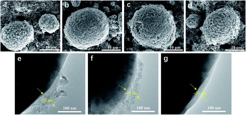
SEM and TEM were used to obtain more insightful information on the morphology of the LiNi0.5Mn0.3Co0.2O2 cathode before and after cycling. Fig. 5 shows the surface morphology of the LiNi0.5Mn0.3Co0.2O2 electrodes before and after 100 cycles in various electrolytes. It was found that the LiNi0.5Mn0.3Co0.2O2 composite had spherical particles with a rough surface, composed of small primary crystals. However, morphology changes were observed for the electrodes after 100 cycles. As shown in Fig. 5b, the LiNi0.5Mn0.3Co0.2O2 composite cycled in EC-based electrolyte showed a smooth topography on the particle surface. The smooth surface was attributed to the consequent growth of SEI on the exposed surface of the LiNi0.5Mn0.3Co0.2O2 composite, accompanied by the decomposition of electrolyte at high voltage. For the electrode cycled in the FEC-based electrolyte (Fig. 5c), LiNi0.5Mn0.3Co0.2O2 particles together with carbon black were relatively uniformly dispersed in the matrix, and a small but detectable morphology change was found. In comparison, neither the obviously detectable morphology change nor the microstructural failure was observed for the LiNi0.5Mn0.3Co0.2O2 composite cycled in LiPO2F2-containing FEC-based electrolyte, even after 100 cycles (Fig. 5d). The thickness of the SEI films of the cycled cathodes in various electrolytes was characterized by TEM. The cathode cycled in the EC-based electrolyte was covered with a non-uniform and agglomerated SEI layer with a thickness of ∼65 nm (Fig. 5e). With the addition of FEC, a slightly thinner SEI film (∼45 nm) was formed on the cathode (Fig. 5f). As shown in Fig. 5g, significant improvements were observed for the cathode cycled in LiPO2F2-containing FEC-based electrolyte. The cathode was coated with a uniform and dense SEI film with a thickness of ∼20 nm, which can ensure facile lithium-ion transport and mitigate the decomposition of the electrolyte. The SEI film formed in the LiPO2F2-containing FEC-based electrolyte was thinner and more stable than that of other electrolytes. Therefore, both FEC and LiPO2F2 should be responsible for the formation of a stable/durable SEI film that can protect the LiNi0.5Mn0.3Co0.2O2 cathode from the erosion of electrolyte.
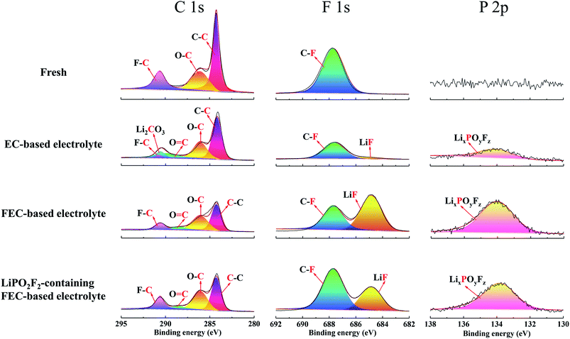
The chemical composition of the cathode surface was studied by X-ray photoelectron spectroscopy (XPS), as shown in Fig. 6. For the C 1s spectra, three peaks were observed for the fresh electrode, C–C (284.8 eV), C–O (286.1 eV) and C–F (290.6 eV), corresponding to conductive carbon, polyether carbon (–CH2CH2O–)n and PVDF binder.40,41 After cycling in EC-based electrolyte, the peak for C–F tended to be small, accompanied by the appearance of two new peaks of C![[double bond, length as m-dash]](https://www.rsc.org/images/entities/char_e001.gif) O (288.5 eV) and Li2CO3 (289.9 eV). These two peaks were caused by the decomposition of electrolyte during long-term cycling under high voltage.42 However, the Li2CO3 peak disappeared and the C
O (288.5 eV) and Li2CO3 (289.9 eV). These two peaks were caused by the decomposition of electrolyte during long-term cycling under high voltage.42 However, the Li2CO3 peak disappeared and the C![[double bond, length as m-dash]](https://www.rsc.org/images/entities/char_e001.gif) O peak weakened for the electrode cycled in FEC-based electrolytes, which suggested that FEC-based electrolytes decomposed less than EC-based electrolytes at high voltages.43 Combined with SEM, TEM, EIS and XPS results, the presence of many decomposition segments such as carbonyl groups can hardly protect the LiNi0.5Mn0.3Co0.2O2 cathode from sustained electrochemical side reactions with the electrolyte. Meanwhile, the thicker SEI layer generated in the EC-based electrolyte seemed to be difficult for Li+ migration.
O peak weakened for the electrode cycled in FEC-based electrolytes, which suggested that FEC-based electrolytes decomposed less than EC-based electrolytes at high voltages.43 Combined with SEM, TEM, EIS and XPS results, the presence of many decomposition segments such as carbonyl groups can hardly protect the LiNi0.5Mn0.3Co0.2O2 cathode from sustained electrochemical side reactions with the electrolyte. Meanwhile, the thicker SEI layer generated in the EC-based electrolyte seemed to be difficult for Li+ migration.
Besides the carbonyl-based organic components, inorganic species also played a crucial role to stabilize the SEI film on the cathode. For the F 1s spectra, the fresh electrode showed the C–F (687.7 eV) peak of PVDF, and this C–F peak was found to be smaller after cycling in the EC-based electrolyte, followed by a small LiF peak (684.8 eV).44 It is well known that LiF is important to form a stable SEI film;19 thus, a SEI formed on the cathode surface in EC-based electrolyte should not be stable. Compared with the EC-based electrolyte, the intensities of both C–F and LiF peaks tended to be larger after cycling in the FEC-based electrolyte. Therefore, in FEC-containing solutions, the SEI on the cathode was enriched with FEC and salt-reduction products, especially for LiF.45 This composition of the surface film ensured long-term stable cycling of the battery in the FEC-based electrolyte. However, LiF has a lower conductivity, and the increase in LiF will result in weak Li+ transmission, which is consistent with the results of the EIS spectra. The excessive LiF was derived from the hydrolysis of LiPF6 (LiPF6 + H2O → POF3 + HF + LiF)46,47 and the defluorination and ring opening of FEC by PF5.45,48,49 In constrast, the LiF peak significantly decreased for the electrode cycled in the LiPO2F2-containing FEC-based electrolyte. It was supposed that LiPO2F2 suppressed the hydrolysis of LiPF6 and the side reaction between FEC and PF5 produced by LiPF6;44,50,51 thus, the amount of LiF can be controlled within a reasonable range,25 which not only reduced the electrochemical impedance of the SEI layer, but also ensured the cycling performance under high voltage.
For the P 2p spectra, the EC-based electrolyte exhibited a small LixPOyFz peak, which originated from the decomposition of LiPF6 during cycling. The FEC-based electrolyte without LiPO2F2 showed the highest LixPOyFz peak, because of the decomposition of LiPF6 and the ring-opening reaction of FEC. However, the LixPOyFz peak became smaller after the addition of LiPO2F2 in the FEC-based electrolyte. Therefore, the decomposition of LiPF6 and the ring-opening reaction of FEC can be effectively inhibited by LiPO2F2, which agreed with the former result of the F 1s spectra.
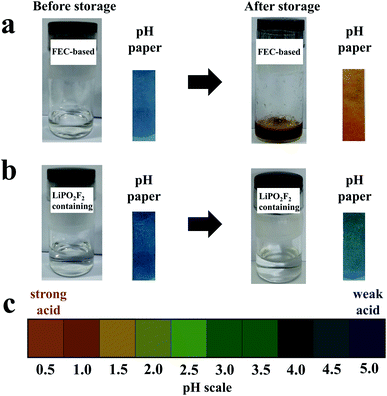
To clarify the suppression of side reactions between FEC and products generated by LiPF6, FEC-based electrolytes with and without LiPO2F2 were stored for several days, respectively. Deionized water (300 ppm) was added to each electrolyte sample before and after introducing LiPO2F2 into the electrolyte to confirm the reactivity of LiPO2F2 toward the products of LiPF6. The changes in the color and pH before and after storage at room temperature for three days are shown in Fig. 7. Before storage, the appearances of the electrolytes with and without LiPO2F2 were similar and the electrolytes were transparent. However, the color of the electrolyte without LiPO2F2 changed from colorless to brown after storage, while almost no change happened for the electrolyte with LiPO2F2. In addition, the pH paper dipped in the electrolyte without LiPO2F2 became red, indicating a strong acid. In contrast, a slight color change was observed for the pH paper dipped in the electrolyte with LiPO2F2. As previously reported,46,47 this was ascribed to the hydrolysis reaction of LiPF6 to form PF5, HF, and POF3, which can react with the FEC solvent to form a colored substance. By adding the LiPO2F2, the hydrolysis of LiPF6 can be suppressed due to the higher promoters of ion-paired LiPF6 dissociation,26,47 resulting in the great stability and ionic conductivity of the electrolyte. Moreover, the PO2F2− as a reaction product may have inhibited the progress of the reaction (POF3 + H2O → PO2F2− + H+ + HF).
4. Conclusion
The electrochemical properties of LiNi0.5Mn0.3Co0.2O2 were investigated under high voltage in EC-based, FEC-based and LiPO2F2-containing FEC-based electrolytes, respectively. The LiNi0.5Mn0.3Co0.2O2 in LiPO2F2-containing FEC-based electrolyte exhibited excellent cycling stability with a reversible capacity of 157.7 mA h g−1 over 200 cycles at 1C rate. The morphology and component analysis of the SEI film on the cathode were characterized by SEM, TEM and XPS, respectively. Based on SEM, TEM and XPS results, the component of SEI was optimized by using the FEC and LiPO2F2 to form a thin and stable SEI layer, which dramatically suppressed the decomposition of the electrolyte. Furthermore, the SEI layer formed in LiPO2F2-containing FEC-based electrolyte had great ionic conductivity, resulting in a significant improvement of the electrochemical performances, including enhanced capacity retention, and superior rate capability. LiPO2F2 can also effectively suppress the side reaction between FEC and products generated by LiPF6 in the electrolyte. These findings will encourage more empirical investigations into the synergistic effect between cosolvents and additives for Li-ion batteries.Conflicts of interest
There are no conflicts to declare.Acknowledgements
This work was financially supported by the National Natural Science Foundation of China (21606135), the Science Technology Innovation Research Program of Ningbo (2019B10113). This work was also sponsored by K. C. Wong Magna Fund in Ningbo University.References
- A. Kraytsberg and Y. Ein-Eli, Adv. Energy Mater., 2012, 2, 922–939 CrossRef CAS.
- M. S. Whittingham, Chem. Rev., 2004, 104, 4271–4301 CrossRef CAS.
- M. M. Thackeray, S.-H. Kang, C. S. Johnson, J. T. Vaughey, R. Benedek and S. A. Hackney, J. Mater. Chem., 2007, 17, 3112–3125 RSC.
- Z. Lu, D. D. MacNeil and J. R. Dahn, Electrochem. Solid-State Lett., 2001, 4, A191–A194 CrossRef CAS.
- L. Yang, B. Ravdel and B. L. Lucht, Electrochem. Solid-State Lett., 2010, 13, A95–A97 CrossRef CAS.
- K. Xu, Chem. Rev., 2014, 114, 11503–11618 CrossRef CAS.
- L. Hu, Z. Zhang and K. Amine, J. Power Sources, 2013, 236, 175–180 CrossRef CAS.
- D. Lu, M. Xu, L. Zhou, A. Garsuch and B. L. Lucht, J. Electrochem. Soc., 2013, 160, A3138–A3143 CrossRef CAS.
- A. Ramasubramanian, V. Yurkiv, T. Foroozan, M. Ragone, R. Shahbazian-Yassar and F. Mashayek, J. Phys. Chem. C, 2019, 123, 10237–10245 CrossRef CAS.
- S. J. Park, J. Y. Hwang, C. S. Yoon, H. G. Jung and Y. K. Sun, ACS Appl. Mater. Interfaces, 2018, 10, 17985–17993 CrossRef CAS.
- J. M. Tarascon, C. Delacourt, A. S. Prakash, M. Morcrette, M. S. Hegde, C. Wurm and C. Masquelier, Dalton Trans., 2004, 19, 2988–2994 RSC.
- T. Achiha, T. Nakajima, Y. Ohzawa, M. Koh, A. Yamauchi, M. Kagawa and H. Aoyama, J. Electrochem. Soc., 2010, 157, A707–A712 CrossRef CAS.
- M. Hu, X. Pang and Z. Zhou, J. Power Sources, 2013, 237, 229–242 CrossRef CAS.
- Z. Zhang, L. Hu, H. Wu, W. Weng, M. Koh, P. C. Redfern, L. A. Curtiss and K. Amine, Energy Environ. Sci., 2013, 6, 1806–1810 RSC.
- A. O. Kondrakov, H. Geßwein, K. Galdina, L. de Biasi, V. Meded, E. O. Filatova, G. Schumacher, W. Wenzel, P. Hartmann, T. Brezesinski and J. Janek, J. Phys. Chem. C, 2017, 121, 24381–24388 CrossRef CAS.
- T. Li, X. Q. Zhang, P. Shi and Q. Zhang, Joule, 2019, 3, 2647–2661 CrossRef CAS.
- P. Verma, P. Maire and P. Novák, Electrochim. Acta, 2010, 55, 6332–6341 CrossRef CAS.
- M. He, L. Hu, Z. Xue, C. C. Su, P. Redfern, L. A. Curtiss, B. Polzin, A. von Cresce, K. Xu and Z. Zhang, J. Electrochem. Soc., 2015, 162, A1725–A1729 CrossRef CAS.
- E. Markevich, G. Salitra, F. Chesneau, M. Schmidt and D. Aurbach, ACS Energy Lett., 2017, 2, 1321–1326 CrossRef CAS.
- G. Salitra, E. Markevich, M. Afri, Y. Talyosef, P. Hartmann, J. Kulisch, Y. K. Sun and D. Aurbach, ACS Appl. Mater. Interfaces, 2018, 10, 19773–19782 CrossRef CAS.
- X. Fan, L. Chen, O. Borodin, X. Ji, J. Chen, S. Hou, T. Deng, J. Zheng, C. Yang, S. C. Liou, K. Amine, K. Xu and C. Wang, Nat. Nanotechnol., 2018, 13, 715–722 CrossRef CAS.
- Y. Li, Y. Li, A. Pei, K. Yan, Y. Sun, C. L. Wu, L. M. Joubert, R. Chin, A. L. Koh, Y. Yu, J. Perrino, B. Butz, S. Chu and Y. Cui, Science, 2017, 358, 506–510 CrossRef CAS.
- Y. Li, W. Huang, Y. Li, A. Pei, D. T. Boyle and Y. Cui, Joule, 2018, 2, 2167–2177 CrossRef CAS.
- K. E. Kim, J. Y. Jang, I. Park, M.-H. Woo, M.-H. Jeong, W. C. Shin, M. Ue and N.-S. Choi, Electrochem. Commun., 2015, 61, 121–124 CrossRef CAS.
- B. Yang, H. Zhang, L. Yu, W. Fan and D. Huang, Electrochim. Acta, 2016, 221, 107–114 CrossRef CAS.
- W. Zhao, G. Zheng, M. Lin, W. Zhao, D. Li, X. Guan, Y. Ji, G. F. Ortiz and Y. Yang, J. Power Sources, 2018, 380, 149–157 CrossRef CAS.
- S. Hong, B. Hong, W. Song, Z. Qin, B. Duan, Y. Lai and F. Jiang, J. Electrochem. Soc., 2018, 165, A368–A370 CrossRef CAS.
- C. Wang, L. Yu, W. Fan, R. Liu, J. Liu, L. Ouyang, L. Yang and M. Zhu, J. Alloys Compd., 2018, 755, 1–9 CrossRef CAS.
- G. Cherkashinin, M. Motzko, N. Schulz, T. Spath and W. Jaegermann, Chem. Mater., 2015, 27, 2875–2887 CrossRef CAS.
- B. J. Hwang, Y. W. Tsai, D. Carlier and G. Ceder, Chem. Mater., 2003, 15, 3676–3682 CrossRef CAS.
- D. Zhou, A. Tkacheva, X. Tang, B. Sun, D. Shanmukaraj, P. Li, F. Zhang, M. Armand and G. Wang, Angew. Chem., Int. Ed., 2019, 58, 6001–6006 CrossRef CAS.
- K. Karuppasamy, P. A. Reddy, G. Srinivas, A. Tewari, R. Sharma, X. S. Shajan and D. Gupta, J. Membr. Sci., 2016, 514, 350–357 CrossRef CAS.
- X. Pan, T. Liu, D. J. Kautz, L. Mu, C. Tian, T. E. Long, P. Yang and F. Lin, J. Power Sources, 2018, 403, 127–136 CrossRef CAS.
- K. Karuppasamy, P. A. Reddy, G. Srinivas, R. Sharma, A. Tewari, G. H. Kumar and D. Gupta, J. Solid State Electrochem., 2016, 21, 1145–1155 CrossRef.
- H.-B. Han, K. Liu, S. W. Feng, S.-S. Zhou, W.-F. Feng, J. Nie, H. Li, X.-J. Huang, H. Matsumoto, M. Armand and Z. B. Zhou, Electrochim. Acta, 2010, 55, 7134–7144 CrossRef CAS.
- X. Sun, H. S. Lee, X. Q. Yang and J. McBreen, Electrochem. Solid-State Lett., 2002, 5, A248–A251 CrossRef CAS.
- H. Zhang, G. Cao, Y. Yang and Z. Gu, J. Am. Chem. Soc., 2008, 46, 30–34 CAS.
- P. L. Taberna, P. Simon and J. F. Fauvarque, J. Electrochem. Soc., 2003, 150, A292–A300 CrossRef CAS.
- R. de Levie, Electrochim. Acta, 1963, 8, 751–780 CrossRef.
- R. Dedryvère, D. Foix, S. Franger, S. Patoux, L. Daniel and D. Gonbeau, J. Phys. Chem. C, 2010, 114, 10999–11008 CrossRef.
- H. Bouayad, Z. Wang, N. Dupré, R. Dedryvère, D. Foix, S. Franger, J. F. Martin, L. Boutafa, S. Patoux, D. Gonbeau and D. Guyomard, J. Phys. Chem. C, 2014, 118, 4634–4648 CrossRef CAS.
- K. Ushirogata, K. Sodeyama, Y. Okuno and Y. Tateyama, J. Am. Chem. Soc., 2013, 135, 11967–11974 CrossRef CAS.
- G. Yan, X. Li, Z. Wang, H. Guo, W. Peng, Q. Hu and J. Wang, J. Solid State Electrochem., 2017, 21, 1589–1597 CrossRef CAS.
- J. Cha, J. G. Han, J. Hwang, J. Cho and N.-S. Choi, J. Power Sources, 2017, 357, 97–106 CrossRef CAS.
- K. Kim, I. Park, S. Y. Ha, Y. Kim, M. H. Woo, M. H. Jeong, W. C. Shin, M. Ue, S. Y. Hong and N.-S. Choi, Electrochim. Acta, 2017, 225, 358–368 CrossRef CAS.
- L. Q. Zheng, S. J. Li, H. J. Lin, Y. Y. Miao, L. Zhu and Z. J. Zhang, Russ. J. Electrochem., 2014, 50, 904–907 CrossRef CAS.
- J. G. Han, K. Kim, Y. Lee and N. S. Choi, Adv. Mater., 2019, 31, 1804822 CrossRef.
- C. Xu, F. Lindgren, B. Philippe, M. Gorgoi, F. Björefors, K. Edström and T. Gustafsson, Chem. Mater., 2015, 27, 2591–2599 CrossRef CAS.
- X. Chen, X. Li, D. Mei, J. Feng, M. Y. Hu, J. Hu, M. Engelhard, J. Zheng, W. Xu, J. Xiao, J. Liu and J. G. Zhang, ChemSusChem, 2014, 7, 549–554 CrossRef CAS.
- C. K. Kim, D. S. Shin, K. E. Kim, K. Shin, J. J. Woo, S. Kim, S. Y. Hong and N.-S. Choi, ChemElectroChem, 2016, 3, 913–921 CrossRef CAS.
- G. Yang, J. Shi, C. Shen, S. Wang, L. Xia, H. Hu, H. Luo, Y. Xia and Z. Liu, RSC Adv., 2017, 7, 26052–26059 RSC.
| This journal is © The Royal Society of Chemistry 2021 |

