 Open Access Article
Edge length-dependent interlayer friction of graphene
Hongwei Zhang *a,
Yanwei Lia,
Jinfeng Qub and
Jingnan Zhanga
aSchool of Urban Planning and Municipal Engineering, Xi'an Polytechnic University, Xi'an 710048, China. E-mail: zhanghongwei@xpu.edu.cn
bSchool of Science, Xi'an Shiyou University, Xi'an 710065, China
First published on 23rd December 2020
Abstract
Edge effects have significant implications in friction at the nanoscale. Despite recent progress, a detailed understanding of the relationship between nanoscale friction and contact edges is still sorely lacking. Here, using molecular dynamics simulations, we investigate the intrinsic effect of the edge size on the nanoscale friction between graphene layers in the incommensurate case based on the model of graphene flakes on a supported graphene substrate. An original rectangular graphene sheet is cut and divided into two independent parts, namely, the inside and outside zones, according to a certain path with a hexagonal boundary. The friction of the inside and the outside flakes placed on a substrate is calculated. The results interestingly reveal that the sum of the friction forces on the inside and outside of flakes, termed the “equivalent friction force”, is substantially greater than that of the original rectangular graphene sheet because the additional edge friction of the former two systems is more than that of the latter system. More importantly, the equivalent friction force is linearly proportional to the edge size due to the larger cropped edge size having more edge friction. This work demonstrates the intrinsic dependence of friction on the contact edge size of incommensurate graphene layers.
1. Introduction
The classical Amontons–Coulomb law of friction has shown that the friction between two solid surfaces is linearly proportional to the applied load and independent of the nominal contact area.1 However, the friction behavior at the nanoscale may be quite different from that at the macroscale, indicating the more complicated nature of friction.2–5 New nanoscale friction phenomena, such as the unique sheet thickness dependence,6–9 negative friction coefficient10,11 and commensurability effect,12–16 are reported. Recent studies have also revealed that nanoscale friction is sensitive to contact edges, especially in the incommensurate contact case.17–22 A fundamental understanding of the relationship between friction and contact edges is very important for various technological applications, including nanoelectromechanical systems (NEMS).Two-dimensional materials, such as graphene, exhibit high edge-to-surface ratios, so contact edge effects are generally not negligible and must be included in the description of friction.17–20,23–26 Contact edges provide an additional edge-related potential barrier, which leads to substantial friction energy dissipation between two contacting surfaces, indicating significant edge effects on nanoscale friction.23 Therefore, it is essential to reveal the friction–contact area relationship and how it relates to edge effects for the design of nanometer devices with optimal mechanical performances.
As an intrinsic “defect”, contact edges are especially influential on the interlayer friction behavior of layered materials and are also dependent on the interlayer commensurability, contact size and shape of sheets.14,19,25,27 In the incommensurate case, friction primarily originates from the atoms of the contact edge region, while the inside atoms contribute less to friction dissipation.17,20,24,26 Recent studies have shown that friction is weakly dependent on the contact area in the incommensurate contact (i.e., lattice mismatch) because friction is dominated primarily by the contact edge.17,21,28,29 For example, molecular dynamics simulations of incommensurate double-walled carbon nanotube oscillators showed that friction is independent of the tube length (i.e., area).17 In contrast, for the commensurate case, the enhancement of the friction force is attributed to the larger contact size because each of the interfacial atoms dissipates significant friction energy, and thus, the friction force increases approximately linearly with the number of contacting atoms.14,17,30 In addition, the related study indicated that commensurability has only a small effect on friction energy dissipation, while the primary source of friction comes from the ends of the nanotubes.18 Despite the great progress made in recent years, many key issues regarding the influence of edge effects on friction behaviors are still unclear. For example, whether and how the intrinsic friction depends on the edge size has not been determined, which is important to obtain an in-depth understanding of the contact area-related nanoscale friction behavior.25 There are still significant challenges and opportunities in this important field, and further research is needed to establish a possible correlation between friction and contact edge size.
In this work, we used molecular dynamics simulations based on a novel computational model of graphene flakes on a supported graphene substrate to investigate the intrinsic dependence of friction on the contact edge length. An original rectangular graphene sheet was cut along a certain hexagonal route and was divided into two parts, hexagonal inside and outside zones, and then, the inside and outside flakes were placed onto a supported graphene substrate surface. Two independent computational systems were constructed. The friction forces of the inside and the outside flakes and the friction of the equivalent flake (i.e., the sum of the inside and the outside flake friction) were calculated. The results interestingly reveal that the equivalent flake friction increased linearly with increasing the edge length of the cutting hexagon, indicating that the contact edge plays a significant role in friction. Our results provide a fundamental understanding of edge-related nanoscale friction.
2. Simulation methods
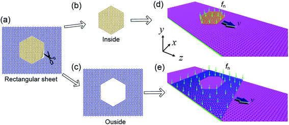
A novel calculational model was constructed as shown in Fig. 1. A defect-free rectangular graphene sheet with a certain size was cut along the boundary of a hexagon as illustrated in Fig. 1(a) and divided into two independent parts: hexagonal inside (Fig. 1(b)) and outside (with a hexagonal hole) zones (Fig. 1(c)). The original rectangular graphene sheet has a lateral dimension of 17.16 nm × 16.73 nm and includes 11![[thin space (1/6-em)]](https://www.rsc.org/images/entities/char_2009.gif) 360C atoms. In the calculations, we chose the original rectangular graphene sheet without a hexagonal hole as the reference sheet. Based on the reference sheet, the inside and the outside areas were cropped with different hexagonal edges, and they were placed on the surface of the substrate. Therefore, two independent computational systems were constructed as shown in Fig. 1(d) and (e), and the relationship between the friction and the hexagonal edge size was investigated. The substrate was composed of double-layered graphene sheets (the bottom layer was fixed), and the front and the rear ends of the substrate layers along the x-axis were all oriented in the armchair direction. Each layer contained 36
360C atoms. In the calculations, we chose the original rectangular graphene sheet without a hexagonal hole as the reference sheet. Based on the reference sheet, the inside and the outside areas were cropped with different hexagonal edges, and they were placed on the surface of the substrate. Therefore, two independent computational systems were constructed as shown in Fig. 1(d) and (e), and the relationship between the friction and the hexagonal edge size was investigated. The substrate was composed of double-layered graphene sheets (the bottom layer was fixed), and the front and the rear ends of the substrate layers along the x-axis were all oriented in the armchair direction. Each layer contained 36![[thin space (1/6-em)]](https://www.rsc.org/images/entities/char_2009.gif) 080C atoms and had a lateral dimension of 17.22 nm × 30.12 nm, which is large enough to ensure the reliability of the results. The flake was in incommensurate contact with the substrate, i.e., the edge of the flake along the x-axis was oriented in the zigzag direction.
080C atoms and had a lateral dimension of 17.22 nm × 30.12 nm, which is large enough to ensure the reliability of the results. The flake was in incommensurate contact with the substrate, i.e., the edge of the flake along the x-axis was oriented in the zigzag direction.
In the simulation, the centers of masses of substrate layers along the in-plane direction were fixed to prevent lateral sliding of the substrate. In addition, rotation of the flake around the normal (y-axis) direction and translation along the x-axis direction were restricted. A non-periodic boundary condition was used in the y-direction, and the periodic boundary conditions were applied in the x- and z-directions. Because the outside flake had the same width as the substrate, its two sides parallel to the z-axis direction could be perfectly connected by the periodic boundary. The graphene flakes had only a hexagonal edge, and the front and rear edges were oriented with respect to the motion direction. We modeled the load as a constant normal force fn on each of the flake atoms, and the total load Nfn on the flake is given by the sum of the loads on all atoms. Under the load, the flake was displaced toward the substrate, and the distance between the flake and the substrate layers was reduced. In all calculations, a constant speed of v = 30 m s−1 was applied to the center of mass of the graphene flake, and then, the flake slid across the substrate surface along the z-axis positive direction. The lateral force (i.e., instantaneous friction) on the flake along the sliding direction was recorded for each time step. The mean friction force was obtained by averaging the value of the lateral force.
The multibody AIREBO potential was used to demonstrate the intralayer covalent C–C bond interaction in graphene,31 and the interlayer interaction between the graphene sheets was described by the Lennard-Jones 12–6 potential, in which the potential well depth ε = 2.968 meV, and the equilibrium distance σ = 3.407 Å.32 The simulation was performed with the NVT ensemble by using a Nosé–Hoover thermostat to keep the simulation system at a room temperature of 300 K, and the time step was set to 1 fs. All the calculations were implemented in the molecular dynamics code LAMMPS.33
3. Results and discussion
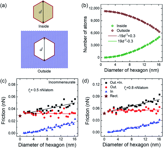
We first investigated the dependence of friction on the size of the cutting hexagon boundary. The friction of the inside and the outside flakes (Fig. 2(a)) on the double-layered graphene substrate were calculated, respectively. Unless otherwise specified, the friction behavior at certain loads of 0.5 and 0.8 nN per atom were considered, and these load values were in agreement with the load applied in previous experimental and computational studies.20,30,34,35 Fig. 2(c) and (d) show that the friction force of the inside flake increased linearly with the increasing diameter of the hexagon d, whereas that of the outside flake was almost constant. Obviously, the number of atoms (or flake area) and edge size of the inside flake all increased with the diameter of the hexagon (Fig. 2(b)). Note that the nanoscale friction behavior for incommensurate graphene layers was dominated by edge atoms, thus increasing the friction as the hexagonal diameter (i.e., edge length) increased.29 In contrast, for the outside flake, the edge size also increased linearly with the increasing diameter of the hexagonal hole, whereas the number of atoms decreased significantly with the increasing diameter (Fig. 2(b)) so that the friction force remained a constant.We defined the sum of the areas of the inside and the outside flakes, termed “equivalent flake”, to analyze the intrinsic dependence of the friction of the equivalent flake (i.e., the sum of friction in the inside and the outside flakes) on the diameter of the hexagon. Interestingly, as the diameter of the hexagon increased, the friction force of the equivalent flake increased linearly (as shown by the “Out.+ In.” dots in Fig. 2(c) and (d)). Note that the equivalent flake area remained constant, which is the exact same size as the original rectangular graphene sheet; however the edge length of the former was 6d larger than that of the latter. Therefore, additional friction energy dissipated on edge atoms, which led to an equivalent flake with more friction. We calculated the friction of the original rectangular graphene sheet (as shown by the five-pointed stars in Fig. 2(c) and (d)). The results show that the friction force of the original rectangular graphene sheet was substantially smaller than that of the equivalent fake.
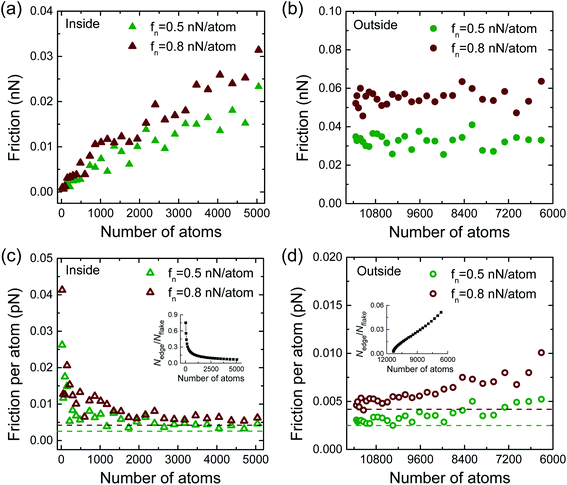
To better understand the dependence of friction on edge length, we considered the variation in friction with various numbers of flake atoms. The results show that the friction force of the inside flake increased significantly with increasing its number of atoms (Fig. 3(a)), whereas the friction force of the outside flake was almost constant (Fig. 3(b)). Comparing the inside flake and the outside flake shows that their friction mechanisms were slightly different. The edge length of the inside flake increased as its number of atoms increased, increasing the friction force on the corresponding edge portion. Although the friction force on each of the inner region atoms was much smaller than that of the edge region atoms for the incommensurate case,20,24,26,36 the friction of the interior portion dissipated moderately, which is likely due to the number of inner atoms increasing rapidly. This suggests that the friction force for the ensemble of the inside flake atoms will increase with increasing its number of atoms (Fig. 3(a)).
For the outside flake, the number of edge atoms also increased with increasing the diameter of the hexagonal hole, increasing the friction force on the edge portion. However, the number of flake inner atoms was reduced, and hence, the friction force of the inner portion atoms deceased. In addition, although the friction dissipated on each of the inner atoms was significantly less than that dissipated on each of the edge atoms,20,24,26,36 the more significant reduction rate of the number of inner portion atoms had considerable frictional variation. Therefore, when the number of the outside flake atoms decreased, the friction force on the edge portion increased, while the inner portion exhibited a corresponding reduction in the friction. Ultimately, the friction force value for the ensemble of the outside flake was likely a constant (Fig. 3(b)).
Furthermore, we considered the average friction force on each atom of the flake, namely, the friction per atom. For the inside flake, apparent friction weakening could be observed, and then, friction dropped rapidly to a relatively steady state (Fig. 3(c)). Actually, the smaller flakes with higher edge-to-surface ratios, for example, flakes comprising 24, 54, 96 and 150 atoms whose proportions of edge atoms amount to 3/4, 5/9, 11/24, and 9/25, respectively (see inset of Fig. 3(c)), would lead to the friction dissipation of the edge atoms, which plays a dominant role in determining the friction.20,23,29,37 Integration of the friction forces on the inner and the edge regions shows that the friction per atom of the small flake was higher than that of the large flake. As the edge-to-surface ratio decreased with the flake size, edge effects gradually weakened,20 and thereby, the friction force on each atom of the flake was gradually reduced because the number of flake atoms always increased. For the outside flake, the friction per atom gradually increased as the number of flake atoms decreased or as the diameter of the hexagon hole increased (Fig. 3(d)). The main reason is that the proportion of flake edge atoms increased almost linearly except for the small flakes (inset of Fig. 3(d)), while the number of flake atoms decreased. Therefore, the friction per atom increased as the number of the outside flake atoms decreased.
We can see also from Fig. 3(c) and (d) that the friction per atom of the inside (outside) flake was always higher than that of the original rectangular sheet (as shown by the dashed lines in Fig. 3(c) and (d)). The friction per atom on the original rectangular flake was 0.0025 and 0.0042 pN per atom (green and red dashed lines, respectively) when the load was 0.5 and 0.8 nN per atom, respectively. We see clearly that the friction per atom of the small flakes (i.e., the inside flake with small diameters and the outside flake with large hole diameters) was significantly larger than that of the original rectangular sheet. However, the friction per atom of the larger flakes (i.e., the inside flake with large diameters and the outside flake with small hole diameters) was comparable to that of the original rectangular sheet.
The distribution of the lateral force acting on the different flake atoms is shown in Fig. 4(a). We believe that the opposite sides of the atoms of the flake are subjected to opposite interactions. Fig. 4(b) shows a snapshot of the lateral force distribution of the flake moving on the substrate. It is clearly shown that a significant resistant force was applied on the front edge, while a driving force was exerted on the rear edge of the flake. The hexagonal diameter of the flake is likely to be reduced by the in-plane squeezing force,9,14,36 indicating the stronger friction interaction of the edge atoms. However, the inner region of the flake will withstand weak interactions from the surrounding substrate atoms. Fig. 4(c) shows a snapshot of the interlayer potential energy between both the flake and the substrate. The results show that the edge atoms had a greater potential energy than the inner region atoms, which also plays a crucial role in determining the friction of the flake edge atoms.
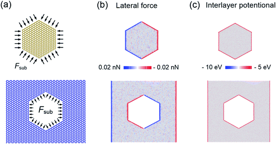 | ||
| Fig. 4 (a) Schematic diagram of the lateral force on the flakes. (b) Lateral force distribution on the flakes. (c) Interlayer potential of the inside and the outside flakes. | ||
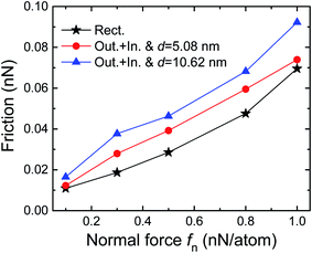
Next, we investigated the dependence of the friction force on the normal load for the inside and the outside flakes with certain hexagonal diameters. Fig. 5 shows that the friction force gradually increased with the increasing load, and this trend is in agreement with the previous reports.24,30,34,38 The friction force of the equivalent flake at each load was higher than that of the original rectangular graphene sheet at the same load in the simulations. Moreover, the equivalent flake with a smaller diameter (d = 5.08 nm) showed a relatively lower frictional value than that of a larger diameter case (d = 10.62 nm). This result further confirms the influence of the cutting boundary on the friction behavior, which indicates that the larger the edge size is, the greater the friction.
We showed that the friction behavior of the graphene flakes was in commensurate contact with the double-layered graphene substrate, where the flake and the substrate layers with edges along the x-direction were all oriented in the zigzag direction. As indicated in Fig. 6(a) and (b), the friction force of the inside flake increased linearly with the diameter of the hexagon, which is consistent with the previous studies, i.e., the friction force is proportional to the flake size.22,30,39 However, the friction of the outside flake exhibited a non-monotonic edge size dependence. The non-monotonic friction force of the outside flake dependence on the edge size originates from two factors: the friction for the commensurate contact layers is positively related to the contact area so that the friction force decreased with the decreasing contact area,17,20 and the nanoscale friction force increased caused by enhancing edge effect.24,25,29 We noted that the number of outside flake atoms is always larger than that of the inside flake atoms, the friction force of the former is always higher than that of the latter. In addition, the friction of the equivalent flake is more affected by the outside flake than the inside flake. Therefore, the equivalent flake reveals the nonmonotonic area dependence of the friction.
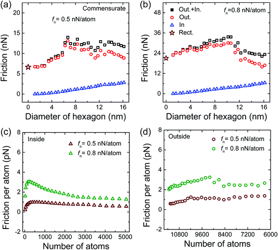 | ||
| Fig. 6 (a) and (b) Friction versus the diameter of the hexagon in the commensurate state. Friction per atom of the inside (c) and the outside flakes (d). | ||
We obtained the friction per atom of the inside and the outside flakes, as shown in Fig. 6(c) and (d). We can see that the friction per atom for the small-sized inside flake changed significantly, which is likely due to its unstable interaction with the substrate layer, which dissipated much more energy; however, the friction per atom of the larger sized flake changed smoothly (Fig. 6(c)). The outside flake contains a larger number of atoms, causing the interlayer interaction to be in a relatively stable state, and therefore, the change trend of the friction per atom is not obvious (Fig. 6(d)).
4. Conclusions
In this study, we investigated the interlayer friction of cut graphene flakes placed on a double-layered graphene substrate and reported a direct correlation between the nanoscale friction and the contact edge length. The results interestingly show that for the incommensurate case, the friction force of the equivalent graphene flake is always greater than that of the original rectangular graphene sheet. Importantly, as the cutting boundary size increases, the friction of the equivalent flake gradually increases linearly. However, for the commensurate case, the friction force of the equivalent flake is a nonmonotonic function of the edge length. In addition, we focus mainly on the fundamental issues of the effect of edge size based a typical hexagonal geometry, which could be the first step to further understanding of the effect of complex edge configurations. The present findings reflect an interesting phenomenon of nanoscale friction, and the friction law will provide theoretical guidance for the design of nanodevices.Conflicts of interest
There are no conflicts to declare.Acknowledgements
The authors would like to acknowledge the support of the National Natural Science Foundation of China (Grant No. 11602139), the Natural Science Basic Research Program of Shaanxi (Grant No. 2019JQ-334), the Scientific Research Program Funded by Shaanxi Provincial Education Department (Grant No. 20JK0849) and the PhD Research Start-up Fund of Xi’an Polytechnic University (Grant No. BS201821).References
- D. Dowson, History of tribology, London, Longman Ltd, 1979 Search PubMed.
- O. Hod, E. Meyer, Q. S. Zheng and M. Urbakh, Nature, 2018, 563, 485–492 CrossRef CAS.
- W. Zhai and K. Zhou, Adv. Funct. Mater., 2019, 29, 1806395 CrossRef.
- S. Zhang, T. Ma, A. Erdemir and Q. Li, Mater. Today, 2019, 26, 67–86 CrossRef CAS.
- Y. Ma, Z. Liu, L. Gao, Y. Yan and L. Qiao, RSC Adv., 2020, 10, 10888–10896 RSC.
- T. Filleter and R. Bennewitz, Phys. Rev. B, 2010, 81, 155412 CrossRef.
- C. G. Lee, Q. Y. Li, W. K. Kalb, X. Z. Liu, H. Berger, R. W. Carpick and J. Hone, Science, 2010, 328, 76–80 CrossRef CAS.
- X. Zeng, Y. Peng and H. Lang, Carbon, 2017, 118, 233–240 CrossRef CAS.
- S. Z. Li, Q. Y. Li, R. W. Carpick, P. Gumbsch, X. Z. Liu, X. Ding, J. Sun and J. Li, Nature, 2016, 539, 541–545 CrossRef CAS.
- Z. Deng, A. Smolyanitsky, Q. Y. Li, X.-Q. Feng and R. J. Cannara, Nat. Mater., 2012, 11, 1032–1037 CrossRef CAS.
- D. Mandelli, W. Ouyang, O. Hod and M. Urbakh, Phys. Rev. Lett., 2019, 122, 076102 CrossRef CAS.
- M. Dienwiebel, G. S. Verhoeven, N. Pradeep, J. W. M. Frenken, J. A. Heimberg and H. W. Zandbergen, Phys. Rev. Lett., 2004, 92, 126101 CrossRef.
- X. Lin, H. W. Zhang, Z. R. Guo and T. C. Chang, Tribol. Int., 2019, 131, 686–693 CrossRef CAS.
- K. Wang, C. Qu, J. Wang, W. Ouyang, M. Ma and Q. Zheng, ACS Appl. Mater. Interfaces, 2019, 11, 36169–36176 CrossRef CAS.
- C. Zhu, P. M. Shenai and Y. Zhao, Nanotechnology, 2012, 23, 015702 CrossRef.
- R. Tong, Z. Quan, Y. Zhao, B. Han and G. Liu, Nanomaterials, 2019, 9, 1617 CrossRef CAS.
- W. L. Guo, Y. F. Guo, H. J. Gao, Q. S. Zheng and W. Y. Zhong, Phys. Rev. Lett., 2003, 91, 125501 CrossRef.
- P. Tangney, S. G. Louie and M. L. Cohen, Phys. Rev. Lett., 2004, 93, 065503 CrossRef.
- P. Liu and Y. W. Zhang, Mol. Simul., 2011, 37, 84–89 CrossRef CAS.
- M. M. van Wijk, M. Dienwiebel, J. W. M. Frenken and A. Fasolino, Phys. Rev. B, 2013, 88, 235423 CrossRef.
- D. Dietzel, M. Feldmann, U. D. Schwarz, H. Fuchs and A. Schirmeisen, Phys. Rev. Lett., 2013, 111, 235502 CrossRef.
- D. Dietzel, C. Ritter, T. Monninghoff, H. Fuchs, A. Schirmeisen and U. D. Schwarz, Phys. Rev. Lett., 2008, 101, 125505 CrossRef.
- Z. R. Guo, T. C. Chang, X. M. Guo and H. J. Gao, Phys. Rev. Lett., 2011, 107, 105502 CrossRef.
- H. W. Zhang, Z. R. Guo, H. Gao and T. C. Chang, Carbon, 2015, 94, 60–66 CrossRef CAS.
- H. W. Zhang and T. C. Chang, Nanoscale, 2018, 10, 2447–2453 RSC.
- K. Wang, W. Ouyang, W. Cao, M. Ma and Q. Zheng, Nanoscale, 2019, 11, 2186–2193 RSC.
- Z. J. Ye, A. Otero-de-la-Roza, E. R. Johnson and A. Martini, Appl. Phys. Lett., 2013, 103, 081601 CrossRef.
- D. Dietzel, T. Mönninghoff, C. Herding, M. Feldmann, H. Fuchs, B. Stegemann, C. Ritter, U. D. Schwarz and A. Schirmeisen, Phys. Rev. B, 2010, 82, 035401 CrossRef.
- C. Qu, K. Wang, J. Wang, Y. Gongyang, R. W. Carpick, M. Urbakh and Q. Zheng, Phys. Rev. Lett., 2020, 125, 126102 CrossRef CAS.
- H. M. Yoon, S. Kondaraju and J. S. Lee, Tribol. Int., 2014, 70, 170–178 CrossRef CAS.
- S. J. Stuart, A. B. Tutein and J. A. Harrison, J. Chem. Phys., 2000, 112, 6472–6486 CrossRef CAS.
- L. A. Girifalco, M. Hodak and R. S. Lee, Phys. Rev. B, 2000, 62, 104–110 CrossRef.
- S. Plimpton, J. Comput. Phys., 1995, 117, 1–19 CrossRef CAS.
- W. Ouyang, I. Azuri, D. Mandelli, A. Tkatchenko, L. Kronik, M. Urbakh and O. Hod, J. Chem. Theory Comput., 2020, 16, 666–676 CrossRef.
- M. Dienwiebel, N. Pradeep, G. S. Verhoeven, H. W. Zandbergen and J. W. M. Frenken, Surf. Sci., 2005, 576, 197–211 CrossRef CAS.
- Y. Peng, J. Li, X. Tang, B. Liu, X. Chen and L. Bai, Tribol. Lett., 2020, 68, 22 CrossRef CAS.
- F. Bonelli, N. Manini, E. Cadelano and L. Colombo, Eur. Phys. J. B, 2009, 70, 449–459 CrossRef CAS.
- Y. F. Guo, W. L. Guo and C. F. Chen, Phys. Rev. B, 2007, 76, 155429 CrossRef.
- Y. Mo, K. T. Turner and I. Szlufarska, Friction laws at the nanoscale, Nature, 2009, 457, 1116–1119 CrossRef CAS.
| This journal is © The Royal Society of Chemistry 2021 |

