
Nickel selenide from single-molecule electrodeposition for efficient electrocatalytic overall water splitting†
Dandan
Chen
,
Yingdong
Chen
,
Wei
Zhang
 * and
Rui
Cao
*
* and
Rui
Cao
*
Key Laboratory of Applied Surface and Colloid Chemistry, Ministry of Education and School of Chemistry and Chemical Engineering, Shaanxi Normal University, Xi’an 710119, China. E-mail: zw@snnu.edu.cn; ruicao@ruc.edu.cn
First published on 17th November 2020
Abstract
The preparation of highly active, low cost and stable electrocatalysts via simple and mild methods for overall water splitting is significant for energy conversion and storage. Herein, we used a nickel selenite complex [{Ni(TMEDA)SeO3}2] to obtain NiSe nanospheres on three-dimensional carbon cloth via electrodeposition. The performance of the as-prepared electrodes (NiSe-TMEDA/CC) was investigated in alkaline solution for water splitting, exhibiting bifunctional OER and HER activity with small overpotentials of 226 and 30.8 mV to achieve a current density of 100 mA cm−2, respectively. Using this bifunctional electrode, a water electrolyzer only required a cell voltage of 1.52 V to deliver a current density of 100 mA cm−2 with excellent long term stability. Compared with the traditional separate Ni and Se sources, the single-molecule precursor is beneficial to form uniform NiSe on the substrate. This work provides a reference for the preparation of bifunctional electrocatalysts for water splitting via single molecule electrodeposition.
1 Introduction
Due to the depletion of traditional fossil energy and the increasing environmental pollution, the search for clean and renewable green energy sources such as solar, wind, tide, and hydrogen has increased.1 However, the use of these new energy sources still has some restrictions. Therefore, the development of efficient, pollution-free and renewable new energy sources to replace traditional fossil fuels has become a hot research topic for researchers. Compared with other new energy sources, hydrogen energy has many advantages (cleanness, high energy density, abundant reserve, high energy conversion efficiency, pollution-free combustion products, feasibility in storage and transportation and recyclability). It is considered to be the most ideal energy carrier in the future energy pattern.2 Electrocatalytic water splitting is an efficient and environmentally friendly hydrogen production technology.3–5 It can be used to prepare high-purity hydrogen through the use of renewable energy or excess electric energy generated by power plants. In water electrolysis, the anodic oxygen evolution reaction (OER) has become the bottleneck6,7 since it is a challenging four-electron and four-proton process. Thus, the development of OER electrocatalysts is urgent for water splitting technology. Meanwhile, to simplify the water electrolyzer and reduce its overall price, it is important to develop bifunctional electrocatalysts for both the hydrogen evolution reaction (HER) and OER.8Owing to the high price and limited reserve of noble metals, precious metal catalysts cannot be used in large-scale production. Therefore, researchers have targeted the first row transition metal elements with low cost and abundant reserves, such as Co,9,10 Ni,11 Cu,12 Fe,13 Mn,14 and Mo.15,16 Various compounds of these elements, such as oxides,17 (oxy)hydroxides,18 chalcogenides,19 phosphides,20 carbides21 and nitrides22 have been studied as electrocatalysts. Among them, nickel-based materials have attracted wide attention due to their characteristic efficiency and low cost.23 In alkaline medium, nickel compounds including oxides and (oxy)hydroxides have proven to exhibit excellent OER activity.24–26 Correspondingly, nickel nitride, phosphide, nitride and chalcogenide have proven to be catalysts with excellent HER activity in acid medium.27 Among the nickel-based electrocatalysts, the chalcogenides have been widely used in the field of overall water splitting due to their good electrocatalytic performance.28,29 In addition, selenides have better conductivity because Se has relatively higher metallicity than S.
The main methods for the preparation of nickel selenides include solid-phase synthesis,30 chemical vapor deposition,31 chemical bath deposition,32 solvothermal methods,33,34 solid–liquid solution methods,35 and hydrothermal methods.36,37 However, these methods usually require high temperature conditions and toxic precursors, and the preparation cost is high. Accordingly, in recent years, electrodeposition38,39 has been widely used to prepare nanomaterials for electrocatalysis. Compared with other synthetic methods, the equipment and operation involved in the electrodeposition method are simple and it can be carried out at ambient temperature and pressure. In addition, the material from electrodeposition can effectively avoid the use of polymer binder in loading electrocatalysts synthesized from other chemical methods. Thus, the simple electrodeposition method can replace the traditional complicated high temperature selenization process and effectively avoid the release of toxic hydrogen selenide gas (H2Se).40 The traditional electrodeposition method for the synthesis of nickel selenide materials generally requires two materials to provide a nickel source and selenium source independently. Alternatively, they can be synthesized through a two-step process (a combination of electrodeposition and other methods). For instance, Zhu et al.41 successfully synthesized nickel selenide nanostructures on Ni foam via a facile electrodeposition route by employing NiCl2 and SeO2 as the Ni and Se sources, respectively. Similarly, an Fe-doped NiSe2/NF electrode was successfully fabricated by Hu et al.42 through a two-step process (an electrodeposition process and a solvothermal selenylation process). Compared with the common methods mentioned above, nickel selenide materials obtained via single-molecule electrodeposition show some advantages. Specifically, the single-molecule complex provides selenium and nickel sources, simultaneously, and then a one-step electrodeposition method can be used to obtain nickel selenides on substrates.
Herein, we demonstrate a simple and fast electrochemical deposition method to deposit a layer of nickel selenide film on a three-dimensional carbon fiber cloth using a nickel–selenium molecular complex [{Ni(TMEDA)SeO3}2]. This green method replaces the traditional complex selenization process and effectively avoids the release of toxic gases. Compared with traditional separate Ni and Se sources, the single molecular precursor is helpful to form uniform NiSe on the substrate. The NiSe-TMEDA/CC electrode exhibited excellent electrocatalytic activity and stability for both the OER (226 mV at 100 mA cm−2) and HER (30.8 mV at 100 mA cm−2) in alkaline electrolyte. When the bifunctional electrode was employed as the cathode and anode for overall water splitting, a low cell voltage of 1.52 V was required to reach a current density of 100 mA cm−2.
2 Results and discussion
After electrodeposition, the surface of the carbon fiber cloth was light green, indicating that the catalyst film was successfully deposited on the CC (Fig. S1a, ESI†). The crystalline phase of the deposited NiSe-TMEDA film on the CC and blank CC were evaluated via powder X-ray diffraction (XRD) (Fig. 1). The evident peaks marked with asterisks correspond to orthorhombic NiSe (JCPDS 29-0935) and the other diffraction peaks are ascribed to the CC and the characteristic peaks of Ni 2p, O 1s and Se 3d, as shown in Fig. S2 (ESI†). The Ni 2p1/2 and Ni 2p3/2 peaks centered at 874.1 and 856.5 eV indicate the Ni2+ state in the deposited film, respectively.43–45 The broad peak near 59.5 eV for Se 3d indicates the presence of surface-oxidized Se species.46,47 In addition, the surface physical properties of the NiSe-TMEDA/CC electrode were analyzed via Raman spectroscopy. The Raman peaks (black line, Fig. S3, ESI†) located at 251, 468, 815 cm−1 indicate the formation of surface NiSeOx species, which is due to the fact that the surface layers of the NiSe species can be easily oxidized. The peak located at 468 cm−1 may arise from the v2 bending mode of the same (SeOx)2− unit, further indicating the formation of surface oxidized species.48 All these observations support the successful preparation of the NiSe film on the CC with the formation of high-valent selenium species on the surface. It is believed that nickel selenite is firstly formed on the surface of the electrode, followed by its reduction into selenide under the applied negative potential. The amine capping ligand can control the release of nickel cation from the electrolyte on the electrode surface to form uniform deposits. | ||
| Fig. 1 XRD patterns of the blank CC and NiSe-TMEDA/CC electrodes compared to that of orthorhombic NiSe (JCPDS 29-0935). | ||
The morphologies of the blank CC and the as-deposited films of NiSe-TMEDA/CC were investigated via scanning electron microscopy (SEM). It is clear that the blank CC showed a three-dimensional cross-linked rod-like structure with a smooth surface (Fig. 2a). After electrochemical deposition, the surface was fully covered with a layer of densely arranged nanospheres (Fig. 2b–e). Moreover, these nanospheres are composed of nanosheets and possess a diameter of about 100–200 nm (Fig. 2e and f). This staggered and closely-aligned structure is conducive to providing abundant catalytically active sites and promoting charge transfer. Energy dispersive X-ray spectroscopy (EDX) analysis was performed to measure the elemental composition of Ni and Se in the electrodes. The EDX analysis (Fig. S4a, ESI†) for the NiSe-TMEDA nanospheres revealed that the atomic ratio of Ni to Se is 1.19![[thin space (1/6-em)]](https://www.rsc.org/images/entities/char_2009.gif) :1, which is close to the expected stoichiometry of NiSe. The EDX spectrum of the blank CC demonstrated the absence of selenium or nickel (Fig. S5, ESI†). The elemental mapping images show that the Ni and Se elements are uniformly distributed throughout the film (Fig. S4c and d, ESI†). The surface species was exfoliated and dispersed on a copper grid for the transition electron microscopy (TEM) analysis. Nano-sized materials with a morphology of flower-like aggregates of nanosheets was observed, as shown in Fig. 2g, which are favourable for mass diffusion during the electrocatalytic process. In addition, it can be seen that the nanosheet of NiSe is thin enough to allow plentiful surface sites for catalysis. The high-resolution TEM (HRTEM) image taken from the sphere (Fig. 2h) shows well-resolved lattice fringes with an interplanar distance of 0.259 nm, which corresponds to the (130) crystal plane of NiSe. All the results support the successful electrochemical deposition of the NiSe sphere film on the CC.
:1, which is close to the expected stoichiometry of NiSe. The EDX spectrum of the blank CC demonstrated the absence of selenium or nickel (Fig. S5, ESI†). The elemental mapping images show that the Ni and Se elements are uniformly distributed throughout the film (Fig. S4c and d, ESI†). The surface species was exfoliated and dispersed on a copper grid for the transition electron microscopy (TEM) analysis. Nano-sized materials with a morphology of flower-like aggregates of nanosheets was observed, as shown in Fig. 2g, which are favourable for mass diffusion during the electrocatalytic process. In addition, it can be seen that the nanosheet of NiSe is thin enough to allow plentiful surface sites for catalysis. The high-resolution TEM (HRTEM) image taken from the sphere (Fig. 2h) shows well-resolved lattice fringes with an interplanar distance of 0.259 nm, which corresponds to the (130) crystal plane of NiSe. All the results support the successful electrochemical deposition of the NiSe sphere film on the CC.
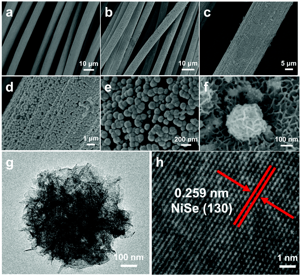 | ||
| Fig. 2 SEM images of the (a) blank CC and (b)–(f) NiSe-TMEDA/CC electrodes. (g) and (h) TEM images of an NiSe sphere exfoliated from the NiSe-TMEDA/CC electrode. | ||
For comparison, we used a traditional synthetic method to deposit a layer of NiSe film (denoted hereafter as NiSe/CC) on the carbon fibre cloth substrate. We used nickel nitrate hexahydrate (Ni(NO3)2·6H2O) as the nickel source and sodium selenite (Na2SeO3) as the selenium source. The SEM image clearly shows that the entire surface of the carbon fibre cloth substrate is unevenly covered with a layer of nickel selenide film of different sizes and agglomerations (Fig. 3a–c). The TEM images clearly show that the exfoliated NiSe from the NiSe/CC film has a random morphology and polycrystals within a particle with lattice fringes of NiSe (Fig. 3d and e). The EDX analysis for these NiSe particles reveals that the atomic ratio between Ni and Se is 1.23:1 (Fig. S6a, ESI†). Both the prepared NiSe and NiSe-TMEDA are Ni-rich. It is believed that the nickel cations can be reduced into metallic form under the strong negative potential during electrodeposition, resulting in Ni-rich NiSe. The elemental mapping images indicate that nickel and selenium elements are evenly distributed on the surface of the substrate (Fig. S6c and d, ESI†). All these results prove that catalyst films with the same composition but different morphologies can be obtained from a physical mixed solution of sodium selenite and nickel nitrate. The use of the single molecule precursor is helpful for the synthesis of uniform nanospheres to provide abundant catalytic sites and efficient mass diffusion.
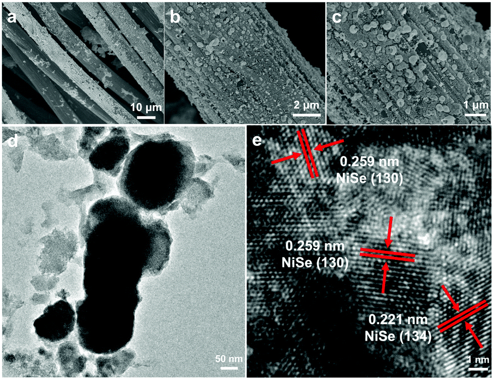 | ||
| Fig. 3 (a)–(c) SEM images of the NiSe/CC electrode. (d) TEM and (e) HRTEM images of the NiSe particles exfoliated from the NiSe/CC electrode. | ||
The OER activity of the NiSe-TMEDA/CC and NiSe/CC (NiSe loading: 3 mg cm−2) electrodes was measured in 1.0 M KOH at a scan rate of 5 mV s−1 using a typical three-electrode system (Fig. 4a). For comparison, similar measurements for blank CC and 20 wt% Ir/C deposited on blank CC were also performed. It should be noted that all the potentials were iR compensated and are against the reversible hydrogen electrode (RHE). The current densities are based on the projected geometric area of the electrodes. Compared with the larger catalytic current density of the NiSe-TMEDA/CC and NiSe/CC films, the blank CC electrode showed extremely weak catalytic current density. In contrast, the NiSe-TMEDA/CC electrode prepared via electrodeposition exhibited a much higher current density and earlier onset potential than the commercial Ir/C catalyst. In addition, the mass loading was also optimized by adjusting the electrodeposition time, and the catalytic results of a series of electrodes are shown in Fig. S7 (ESI†). The oxidation peaks at 1.37 V of NiSe-TMEDA/CC and NiSe/CC can be attributed to the oxidation of Ni2+ to Ni3+.49 Compared with NiSe/CC, NiSe-TMEDA/CC showed higher activity. Small overpotentials of 226, 265 and 282 mV were required to achieve current densities of 100, 200 and 300 mA cm−2, respectively. The non-faradaic currents in electrolysis on electrodes with large surface areas are usually significant. Nevertheless, it is acceptable to report overpotentials based on the LSV results. We also measured the cathodic sweep curve and calculated the overpotential of OER. When the current density reached 100 mA cm−2, the overpotential of the NiSe-TMEDA/CC electrode for the OER was 245 mV, which is 19 mV higher than the value tested in LSV (Fig. S8, ESI†). The Tafel slopes of NiSe-TMEDA/CC and NiSe/CC are 84 and 120 mV dec−1, respectively, implying a more rapid OER rate for the NiSe-TMEDA/CC electrode (Fig. 4c). The turnover frequency (TOF) was calculated to evaluate the intrinsic OER activities of NiSe-TMEDA/CC. The TOF value at the overpotential of 400 mV was estimated to be 0.97 s−1. We further tested the long-term electrochemical stability of the electrodes in 1 M KOH. As observed, the potential required to reach a current density of 100 mA cm−2 stabilized at 1.63 V within the first 20 h, and then stabilized at 1.66 V within the last 40 hours of electrolysis for NiSe-TMEDA/CC during 60 h of reaction (Fig. S9, ESI†). Notably, the potential in the electrolysis was higher than that in the LSV studies under a similar current density. The higher potential in the electrolysis occurred because of the following two reasons. Firstly, the electrolysis experiments were recorded without iR compensation of the cell. The actual potential of the anode would be less than 1.66 V. Secondly, in the long-term electrolysis process, the amount of gas generated was large. Even under stirring conditions, there was still a large amount of bubbles accumulated on the substrate that could not be released in time. Due to the mass/charge-diffusion limitation, this resulted in an intrinsically lower current density. Specifically, the voltage required to reach a certain current density is larger than in the LSV test. The SEM images in Fig. 5a and b show the morphology of the electrode after the OER electrolysis, which still maintained the full coverage of NiSe on substrate with negligible change.
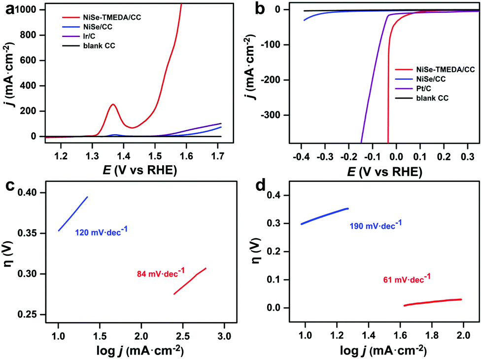 | ||
| Fig. 4 (a) OER and (b) HER polarization curves of the blank CC, NiSe/CC, NiSe-TMEDA/CC and Ir (or Pt)/CC electrodes. The Tafel plots of the NiSe/CC (blue line) and NiSe-TMEDA/CC (red line) electrodes for the (c) OER and (d) HER. | ||
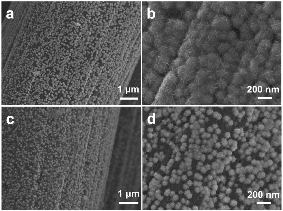 | ||
| Fig. 5 SEM images of the NiSe-TMEDA/CC electrode after 20 h of OER (a) and (b) and HER (c) and (d) electrolysis. | ||
In the process of the OER, the surface species of metal selenides were reconstructed to form the actual active species.49 As shown in Fig. S10 (ESI†), the composition of the post-OER NiSe-TMEDA/CC electrode was studied via XPS measurement. A new peak appeared at the binding energy of 857.2 eV in the Ni 2p spectrum, revealing the formation of high-valent nickel species of NiOOH.49 After OER electrolysis, the XPS peak of Ni 2p3/2 shifted slightly from 856.5 eV (Fig. S10b, ESI†) to 855.7 eV, which is consistent with the literature on the Ni 2p binding energies of nickel oxyhydroxide and selenite species.46,47,50 In addition, the peak intensity of (SeOx)2− in the Se 3d spectrum increased, while the peak of Se2− at 54.9 eV disappeared, indicating that the surface of NiSe-TMEDA/CC was oxidized. The surface Raman spectrum analysis (Fig. S3, ESI† red line) after OER electrolysis also confirms the formation of nickel oxyhydroxide species, with Raman peaks ranging from 444 to 630 cm−1.51 All these results suggest the evolution of oxidized species during the OER process.40 According to the previous research, the effect of the Fe impurities from the electrolyte or the material cannot be ruled out since a trace amount of Fe can significantly enhance the OER activity of NiOOH species.51–55
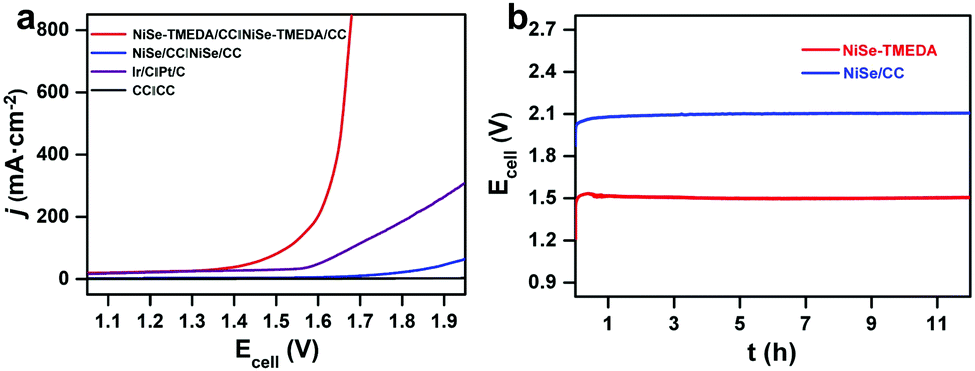
The electrocatalytic HER performance of NiSe-TMEDA/CC, NiSe/CC, blank CC and Pt/C (20 wt%) deposited on CC were also studied in 1.0 M KOH solution via LSV at a scan rate of 5 mV s−1. As shown in Fig. 4b, similarly, the blank CC electrode displayed negligible HER catalytic activity, while Pt/C exhibited high activity with a small onset potential but poor performance at large currents. Compared with NiSe/CC, NiSe-TMEDA/CC exhibited much better activity toward the HER with an earlier onset potential. The overpotentials were only 31, 33, and 36 mV to achieve HER current densities of 100, 200, and 400 mA cm−2. The Tafel slope for NiSe-TMEDA/CC was as low as 61 mV dec−1, which is smaller than that of NiSe/CC (190 mV dec−1), indicating favourable HER kinetics for NiSe-TMEDA/CC (Fig. 4d) and suggesting a Volmer–Heyrovsky mechanism.56 The TOF value at the overpotential of 250 mV was estimated to be 1.93 s−1. In Fig. S9 (ESI†), the potential required for the NiSe-TMEDA/CC electrode to maintain a stable current density of 100 mA cm−2 stabilized at −0.25 V during 60 h electrolysis. The SEM images in Fig. 5c and d show that the CC surface still maintained its coverage of NiSe with little morphological change after the HER electrolysis. All these results prove that the NiSe-TMEDA/CC electrode has strong stability in a strong alkaline solution under HER conditions. The surface composition of the post-HER NiSe-TMEDA/CC electrode was also studied by XPS measurement (Fig. S11, ESI†). The Ni 2p spectrum (Fig. S11b, ESI†) suggests the absence of Ni3+.39 In addition, the Se 3d spectrum (Fig. S11d, ESI†) reveals a decrease in the surface (SeOx)2− species and increased in the Se2− species at 55.8 eV. The long-term HER electrolysis applied a reduction potential to the catalyst and reduced the high-valent Se species into NiSe. The surface Raman spectrum (Fig. S3, ESI† blue line) also indicates that the amount of surface high-valent Se species decreased. To reflect the real catalytic activity, the electrochemical active surface area (ECSA) and roughness factor (RF) of NiSe-TMEDA/CC and NiSe/CC were evaluated using the double-layer capacitance (Cdl), which was estimated by the CV at different scan rates in the non-faradaic regions (Fig. S12, ESI†). The slope of the charging current (ic) versus the scan rate (ν) represents the Cdl of NiSe-TMEDA/CC and NiSe/CC, which is 347 μF and 252 μF, respectively. The ECSA and RF of NiSe-TMEDA/CC were calculated to be 14.96 cm2 and 59.84, while they are 10.08 cm2 and 40.32 for NiSe/CC, respectively. These results show that NiSe-TMEDA/CC has a larger specific surface area and more active sites. Considering that the NiSe-TMEDA/CC electrode is efficient and stable toward both the OER and HER in strongly basic medium, we used NiSe-TMEDA/CC as both the anode and cathode to test its performance in electrocatalytic overall water splitting performance in a two-electrode cell. For comparison, we also tested the overall water splitting performance of two-electrode systems consisting of blank CC (CC‖CC), NiSe/CC (NiSe/CC‖NiSe/CC) and Ir/C and Pt/C (Ir/C‖Pt/C) under the same conditions, and Fig. 6a shows the polarization curves of the corresponding electrodes, with a scan rate of 5 mV s−1. The NiSe/CC‖NiSe/CC, Ir/C‖Pt/C and CC‖CC cells delivered a poor water-splitting current, while the NiSe-TMEDA/CC‖NiSe-TMEDA/CC cell showed a high performance with a cell voltage of only 1.52 V to reach a current density of 100 mA cm−2. The comparison of the overall alkaline water splitting performance of NiSe-TMEDA/CC with that of other bifunctional catalysts is summarized in Table S1 (ESI†). The results affirmed that NiSe-TMEDA/CC prepared via electrodeposition with a single molecular complex exhibits excellent activity for overall water splitting. Fig. 6b shows the stability test for the NiSe-TMEDA/CC‖NiSe-TMEDA/CC cell in 1 M KOH solution. The results show that for the NiSe-TMEDA/CC‖NiSe-TMEDA/CC cell, the voltage was basically stable at 1.5 V to reach a current density of 50 mA cm−2, while the voltage of the NiSe/CC‖NiSe/CC cell gradually increased. The faradaic efficiencies of the HER and OER were recorded by analysing the experimental (gas chromatography) and theoretical (from the quantity of passed charge) amounts of generated gasses, showing average values of 97.13% and 96.18%, respectively (Fig. S13, ESI†).
 | ||
| Fig. 6 Water electrolysis performance of the cells with different electrodes in terms of (a) LSV and (b) electrolysis at a current density of 50 mA cm−2. | ||
3 Experimental section
3.1 General materials
All chemicals were commercially available and were used without further purification. Ni(NO3)2·6H2O (99.999%) and TMEDA were purchased from Energy Chemical. Na2SeO3 (99.999%) was purchased from Alfa Aesar. Ethanol (99.5%) was purchased from Sigma-Aldrich. KOH (98%) and HCl were purchased from Sinopharm Group Chemical Reagent Co., Ltd. Ir/C (20 wt% Ir) and Pt/C (20 wt% Pt) on Vulcan XC-72R were purchased from Premetek Co. Nafion (5 wt%) was purchased from DuPont. In all the experiments, Milli-Q water of 18.2 MΩ cm was used.3.2 Synthesis of [Ni(TMEDA)(SeO3)] complex (Ni-TMEDA)
An aqueous solution (10 mL) of Na2SeO3 (0.173 g, 1 mmol) was added to an ethanol solution (15 mL) of TMEDA (0.150 mL, 1 mmol) and Ni(NO3)2·6H2O (0.290 g, 1 mmol). A small amount of light-green NiSeO3 precipitated, while stirring at room temperature. After 30 min, the green mixture of Ni-TMEDA complex was filtered and washed with ethanol three times. Finally, green crystals were obtained by slow evaporation of the solvent, and then dried at 60 °C for 10 h.3.3 Electrodeposition of NiSe on carbon cloth
NiSe was grown on carbon cloth (CC) substrates via electrodeposition. Prior to the electrodeposition, the CC (0.5 cm × 2 cm) was washed with acetone for 30 min to ensure surface pollutants were removed, and subsequently rinsed with ethanol several times to clean it well. The electrodeposition was performed in a typical three-electrode cell configuration, where the working electrode was the CC (0.5 cm × 0.5 cm), the reference electrode was saturated Ag/AgCl and the counter electrode was a graphite rod. NiSe was electrodeposited on the CC in an Ni-TMEDA complex aqueous solution (10 mL, 3 mmol) using a CHI 660E electrochemical analyzer. The experiment was performed at room temperature without stirring. The pH was maintained at 3.0 using HCl, which also prevented the formation of hydroxyl species and insoluble compounds. Electrodeposition was carried out by controlled potential electrolysis of −1.4 V (vs. Ag/AgCl) on the CC under ambient atmosphere for 40 min. After deposition, the electrode was removed from the cell and washed with deionized water several times and then dried at room temperature. The prepared electrode was denoted as NiSe-TMEDA/CC. The loading of NiSe on the carbon cloth was determined to be 3 mg cm−2. The NiSe/CC electrode was prepared using a similar method with minor modifications from an electrolyte bath comprised of nickel nitrate hexahydrate (3 mmol) and sodium selenite (3 mmol). The pH of the mixture was also maintained at 3.0 using HCl.3.4 Preparation of Pt/C- and Ir/C-loaded electrodes
To prepare the Pt/C- and Ir/C-loaded electrodes, 5 mg Pt/C and Ir/C were dispersed in 1 mL of water–ethanol solution at a volume ratio of 2:1 by ultrasonication for 1 h to form a homogeneous suspension. The loading of Pt/C and Ir/C catalyst on the CC was performed through a drop casting method. 150 μL of the mixture was loaded onto the CC electrode working area.
3.5 Characterization
The XRD patterns of the as-prepared electrodes were acquired on a X-ray diffractometer (Rigaku D/Max 2550VB+/PC, Cu Kα, λ = 1.5406 Å, 40 kV and 100 mA). Raman spectra were recorded on a Renishaw inVia Reflex confocal Raman microscope. X-Ray photoelectron spectroscopy (XPS) was carried out on a Kratos AXIS ULTRA XPS. Corrections of the binding energy were carried out using the C 1s peak at 284.8 eV. The morphologies of the as-prepared electrodes surfaces were observed with a scanning electron microscope (SEM, Hitachi, TM3000; SEM, FEI, Quanta 200; SEM, Hitachi, SU8020). TEM images of the surface NiSe on the CC were obtained with a transmission electron microscope (TEM, JEOL, JEM-2100). Energy-dispersive X-ray analysis (EDX) was conducted on an AMETEK Materials Analysis EDX equipped on the TEM.3.6 Electrochemical studies
Electrochemical experiments were performed with a CHI 660E electrochemical analyzer (CH Instruments, Inc., Shanghai) at room temperature. A standard three-electrode system, which consisted of saturated Ag/AgCl as the reference electrode, a graphite rod as the counter electrode, and NiSe-TMEDA/CC as the working electrode (0.5 cm × 0.5 cm), was used for the electrochemical experiments. The Ag/AgCl reference electrode was calibrated by CV tests in a K3Fe(CN)6/K4Fe(CN)6 aqueous solution. All potentials in this study are reported against the reversible hydrogen electrode (RHE) based on the equation: ERHE = EAg/AgCl + (0.197 + 0.0591 × pH) V. Linear sweep voltammograms (LSVs), at a scan rate of 5 mV s−1, were recorded in 15 mL of 1 M KOH aqueous solution. Controlled potential electrolysis was recorded under the same experimental setup without iR drop compensation. The Tafel plots were derived from the steady state currents. The current density was calculated based on the geometric area of the electrodes. The two-electrode setup for alkaline water electrolysis was fabricated using the NiSe-TMEDA/CC electrode as both the anode and cathode. The two-electrode LSV and electrolysis were performed in 1 M KOH solution at room temperature. The electrochemical active surface area (ECSA) and roughness factor (RF) of NiSe-TMEDA/CC and NiSe/CC were evaluated using the double layer capacitance (Cdl), which was estimated from CV at different scan rates in the non-faradaic regions. Firstly, different scan rates were set to measure the cyclic voltammetry curve of the sample. Then, the current densities at a given potential were plotted against the scan rates to fit a linear curve. The slope of the curve obtained from the linear fitting is the double layer capacitance (Cdl) of the corresponding catalyst material. The ECSA was obtained according to formula ECSA = Cdl/Cs (the value of Cs for the studied catalysts is 25 μF cm−2) and RF was obtained based on RF = ECSA/Sg (Sg is the geometric area of the electrode, 0.25 cm−2).3.7 TOF calculation
TOF was calculated according to the following eqn (1). | (1) |
4 Conclusions
In summary, NiSe-TMEDA nanospheres grown on carbon cloth via single-molecule electrodeposition showed excellent electrocatalytic activity and durability toward both the OER and HER in alkaline medium. The NiSe-TMEDA/CC electrode was employed in a two-electrode alkaline electrolyzer for overall water splitting, achieving a current density of 100 mA cm−2 with a small cell voltage of 1.52 V. This high performance is attributed to the unique morphology of the NiSe species as a result of the novel single-molecule electrodeposition. The nanospheres were composed of thin nanosheets, which could provide abundant catalytic sites and efficient mass diffusion. Meanwhile, the electrodeposited film consisted of uniform nanospheres due to the single-molecule precursor. The electrode displayed a superior OER and HER performance compared with NiSe obtained via traditional electrodeposition. Therefore, this study provides a novel method for the preparation of efficient and cheap bifunctional electrocatalysts for water splitting.Conflicts of interest
There are no conflicts to declare.Acknowledgements
We are grateful for the Starting Research Funds of Shaanxi Normal University and the National Natural Science Foundation of China (Grant No. 21773146 and 21872092).Notes and references
- Q. Wang and K. Domen, Chem. Rev., 2020, 120, 919–985 CrossRef CAS.
- W. Zhang, W. Lai and R. Cao, Chem. Rev., 2017, 117, 3717–3797 CrossRef CAS.
- S. Dou, L. Tao, R. Wang, S. El Hankari, R. Chen and S. Wang, Adv. Mater., 2018, 30, 1705850 CrossRef.
- Y. Yan, T. He, B. Zhao, K. Qi, H. Liu and B. Xia, J. Mater. Chem. A, 2018, 6, 15905–15926 RSC.
- Z. Zhang, S. Liu, J. Xiao and S. Wang, J. Mater. Chem. A, 2016, 4, 9691–9699 RSC.
- R. A. Hussain and I. Hussain, J. Solid State Chem., 2019, 277, 316–328 CrossRef CAS.
- Y. Yang, Y. Kang, H. Zhao, X. Dai, M. Cui, X. Luan, X. Zhang, F. Ni, Z. Ren and W. Song, Small, 2019, 16, 1905083 CrossRef.
- X. Wang, T. Ouyang, L. Wang, J. Zhong, T. Ma and Z. Liu, Angew. Chem., Int. Ed., 2019, 58, 13291–13296 CrossRef CAS.
- S. Wan, J. Qi, W. Zhang, W. Wang, S. Zhang, K. Liu, H. Zheng, J. Sun, S. Wang and R. Cao, Adv. Mater., 2017, 29, 1700286 CrossRef.
- J. Tian, Q. Liu, A. M. Asiri and X. Sun, J. Am. Chem. Soc., 2014, 136, 7587–7590 CrossRef CAS.
- W. Zhou, X. Wu, X. Cao, X. Huang, C. Tan, J. Tian, H. Liu, J. Wang and H. Zhang, Energy Environ. Sci., 2013, 6, 2921–2924 RSC.
- M. Zhang, Z. Chen, P. Kang and T. J. Meyer, J. Am. Chem. Soc., 2013, 135, 2048–2051 CrossRef CAS.
- M. Li, T. Liu, X. Bo, M. Zhou, L. Guo and S. Guo, Nano Energy, 2017, 33, 221–228 CrossRef CAS.
- H. Liu, X. Gao, X. Yao, M. Chen, G. Zhou, J. Qi, X. Zhao, W. Wang, W. Zhang and R. Cao, Chem. Sci., 2019, 10, 191–197 RSC.
- X. Xue, J. Zhang, I. A. Saana, J. Sun, Q. Xu and S. Mu, Nanoscale, 2018, 10, 16531–16538 RSC.
- I. S. Amiinu, Z. Pu, X. Liu, K. A. Owusu, H. G. R. Monestel, F. O. Boakye, H. Zhang and S. Mu, Adv. Funct. Mater., 2017, 27, 1702300 CrossRef.
- H. Jin, J. Wang, D. Su, Z. Wei, Z. Pang and Y. Wang, J. Am. Chem. Soc., 2015, 137, 2688–2694 CrossRef CAS.
- X. Gao, Y. Chen, T. Sun, J. Huang, W. Zhang, Q. Wang and R. Cao, Energy Environ. Sci., 2020, 13, 174–182 RSC.
- A. Sivanantham, P. Ganesan and S. Shanmugam, Adv. Funct. Mater., 2016, 26, 4661–4672 CrossRef CAS.
- Y. Li, H. Zhang, M. Jiang, Q. Zhang, P. He and X. Sun, Adv. Funct. Mater., 2017, 27, 1702513 CrossRef.
- L. Liao, S. Wang, J. Xiao, X. Bian, Y. Zhang, M. D. Scanlon, X. Hu, Y. Tang, B. Liu and H. H. Giraultb, Energy Environ. Sci., 2014, 7, 387–392 RSC.
- M. NShalom, D. Ressnig, X. Yang, G. Clavel, T. P. Fellinger and M. Antonietti, J. Mater. Chem. A, 2015, 3, 8171–8177 RSC.
- C. C. L. McCrory, S. Jung, I. M. Ferrer, S. M. Chatman, J. C. Peters and T. F. Jaramillo, J. Am. Chem. Soc., 2015, 137, 4347–4357 CrossRef CAS.
- J. A. Bau, E. J. Luber and J. M. Buriak, ACS Appl. Mater. Interfaces, 2015, 7, 19755–19763 CrossRef CAS.
- Z. Zhang, S. Liu, F. Xiao and S. Wang, ACS Sustainable Chem. Eng., 2016, 5, 529–536 CrossRef.
- Z. Zhang, Z. Yi, J. Wang, X. Tian, P. Xu, G. Shi and S. Wang, J. Mater. Chem. A, 2017, 5, 17064–17072 RSC.
- P. Luo, H. Zhang, L. Liu, Y. Zhang, J. Deng, C. Xu, N. Hu and Y. Wang, ACS Appl. Mater. Interfaces, 2017, 9, 2500–2508 CrossRef CAS.
- X. Luo, P. Ji, P. Wang, R. Cheng, D. Chen, C. Lin, J. Zhang, J. He, Z. Shi, N. Li, S. Xiao and S. Mu, Adv. Energy Mater., 2020, 10, 1903891 CrossRef CAS.
- H. C. Tsai, B. Vedhanarayanan and T. W. Lin, ACS Appl. Energy Mater., 2019, 2, 3708–3716 CrossRef CAS.
- H. Sun, Z. Liang, K. Shen, M. Luo, J. Hu, H. Huang, Z. Zhu, Z. Li, Z. Jiang and F. Song, Appl. Surf. Sci., 2018, 428, 623–629 CrossRef CAS.
- A. Panneerselvam, M. A. Malik, M. Afzaal, P. O’Brien and M. Helliwell, J. Am. Chem. Soc., 2008, 130, 2420–2421 CrossRef CAS.
- P. A. Nwofe, R. A. Chikwen, P. E. Agbo and H. U. Igwe, Asian J. Sci. Res., 2016, 10, 43–49 CrossRef.
- X. Shi, J. Key, S. Ji, V. Linkov, F. Liu, H. Wang, H. Gai and R. Wang, Small, 2018, 15, 1802861 CrossRef.
- Q. Jiang, R. Chen, H. Chen, J. Jiang, X. Yang, Y. Ju, R. Ji and Y. Zhang, J. Mater. Sci., 2018, 53, 7672–7682 CrossRef CAS.
- K. Xu, H. Ding, K. Jia, X. Lu, P. Chen, T. Zhou, H. Cheng, S. Liu, C. Wu and Y. Xie, Angew. Chem., Int. Ed., 2016, 55, 1710–1713 CrossRef CAS.
- V. Murugadoss, J. Lin, H. Liu, X. Mai, T. Ding, Z. Guo and S. Angaiah, Nanoscale, 2019, 11, 17579–17589 RSC.
- S. Wang, P. He, L. Jia, M. He, T. Zhang, F. Dong, M. Liu, H. Liu, Y. Zhang, C. Li, J. Gao and L. Bian, Appl. Catal., B, 2019, 243, 463–469 CrossRef CAS.
- Y. Wang, G. Zhang, W. Xu, P. Wan, Z. Lu, Y. Li and X. Sun, ChemElectroChem, 2014, 1, 1138–1144 CrossRef CAS.
- P. Liu, L. Zhang, L. Zheng and H. Yang, Mater. Chem. Front., 2018, 2, 1725–1731 RSC.
- Z. Gao, J. Qi, M. Chen, W. Zhang and R. Cao, Electrochim. Acta, 2017, 224, 412–418 CrossRef CAS.
- J. Zhu and Y. Ni, CrystEngComm, 2018, 20, 3344–3352 RSC.
- X. Hu, Q. Zhou, P. Cheng, S. Su, X. Wang, X. Gao, G. Zhou, Z. Zhang and J. Liu, Appl. Surf. Sci., 2019, 488, 326–334 CrossRef CAS.
- Y. Wen, S. Peng, Z. Wang, J. Hao, T. Qin, S. Lu, J. Zhang, D. He, X. Fan and G. Cao, J. Mater. Chem. A, 2017, 5, 7144–7152 RSC.
- Z. Zou, X. Wang, J. Huang, Z. Wu and F. Gao, J. Mater. Chem. A, 2019, 7, 2233–2241 RSC.
- B. Zhang, Y. Lui, L. Zhou, X. Tang and S. Hu, J. Mater. Chem. A, 2017, 5, 13329–13335 RSC.
- M. C. Biesinger, B. P. Payne, L. W. M. Lau, A. Gersonb and R. S. C. Smart, Surf. Interface Anal., 2009, 41, 324–332 CrossRef CAS.
- C. Tang, Z. Pu, Q. Liu, A. M. Asiri, X. Sun, Y. Luo and Y. He, ChemElectroChem, 2015, 2, 1903–1907 CrossRef CAS.
- R. L. Frost and E. C. Keeffe, J. Raman Spectrosc., 2009, 40, 509–512 CrossRef CAS.
- D. Song, H. Wang, X. Wang, B. Yu and Y. Chen, Electrochim. Acta, 2017, 254, 230–237 CrossRef CAS.
- C. Tang, N. Cheng, Z. Pu, W. Xing and X. Sun, Angew. Chem., Int. Ed., 2015, 54, 9351–9355 CrossRef CAS.
- M. W. Louie and A. T. Bell, J. Am. Chem. Soc., 2013, 135, 12329–12337 CrossRef CAS.
- D. A. Corrigan and R. M. Bender, J. Electrochem. Soc., 1989, 136, 723–727 CrossRef CAS.
- D. Friebel, M. W. Louie, M. Bajdich, K. E. Sanwald, Y. Cai, A. M. Wise, M. J. Cheng, D. Sokaras, T. C. Weng, R. Alonso-Mori, R. C. Davis, J. R. Bargar, J. K. Norskov, A. Nilsson and A. T. Bell, J. Am. Chem. Soc., 2015, 137, 1305–1313 CrossRef CAS.
- H. S. Ahn and A. J. Bard, J. Am. Chem. Soc., 2016, 138, 313–318 CrossRef CAS.
- S. Anantharaj and S. Noda, Int. J. Hydrogen Energy, 2020, 45, 15763–15784 CrossRef CAS.
- Y. Li, H. Wang, L. Xie, Y. Liang, G. Hong and H. Dai, J. Am. Chem. Soc., 2011, 133, 7296–7299 CrossRef CAS.
Footnote |
| † Electronic supplementary information (ESI) available. See DOI: 10.1039/d0nj04966b |
| This journal is © The Royal Society of Chemistry and the Centre National de la Recherche Scientifique 2021 |