Noble-metal-free hexagonal wurtzite CdS nanoplates with exposed (110) and (112) crystal facets for efficient visible-light H2 production†
Chao
Zhang
 abc,
Xi
Cheng
a,
Baoquan
Liu
a,
Zhenmei
Guo
a,
Guangxiang
He
 *b and
Zhiguo
Lv
 *a
*a
aKey Laboratory of Multiphase Flow Reaction and Separation Engineering of Shandong Province, State Key Laboratory Base for Eco-chemical Engineering, College of Chemical Engineering, Qingdao University of Science and Technology, Qingdao 266042, China. E-mail: lvzhiguo@qust.edu.cn; hgx@bipt.edu.cn
bBeijing Key Laboratory of Fuel Cleanliness and Efficient Catalytic Emission Reduction Technology, School of Chemical Engineering, Beijing Institute of Petrochemical Technology, Beijing 102617, China
cKey Laboratory of Advanced Energy Materials Chemistry (Ministry of Education), College of Chemistry, Nankai University, Tianjin 300071, China
First published on 24th November 2020
Abstract
Hexagonal wurtzite CdS has been regarded as one of the most promising semiconductors for photocatalysis. However, its water splitting performance under visible-light irradiation is seriously limited due to the high charge carrier recombination. In order to solve this limitation, we facilely prepared 2D hexagonal wurtzite CdS nanoplates (HWCs) with exposed (110) and (112) crystal facets via a water bath strategy. The visible-light responsivity of the HWCs exhibited an obvious red shift and, accordingly, the band gap was narrowed from 2.31 to 2.12 eV. Besides, the HWCs showed an excellent visible-light H2 evolution rate of ca. 6214.5 μmol h−1 g−1 without cocatalysts due to the enhanced charge carrier separation between the (110) and (112) crystal facets. Finally, a possible photocatalytic mechanism for HWCs was tentatively proposed. This work will be beneficial for designing and fabricating powerful mono-component photocatalysts.
1. Introduction
In recent years, researchers have continued to exploit various renewable energy carriers and, among them, hydrogen may be one of the most promising candidates due to its sustainable, environmental and low-cost features.1 Since Fujishima and Honda found the photocatalytic water splitting phenomenon in 1972, photocatalysis has been considered as a prospective strategy to produce H2.2 To achieve high H2 production performance, numerous photocatalysts (mainly divided into mono-component catalysts and heterostructure catalysts) have been developed.3,4 Among them, preparing mono-component catalysts (e. g. CdS, MoS, g-C3N4, TiO2, and ZnO, etc.) could avoid complex fabrication processes and multitudinous influencing factors.5–7 However, up to now, the visible-light H2 production activities of these mono-component catalysts have generally been low (ca. 0–2000 μmol h−1 g−1).8–10 Noble metal nanoparticles (e. g. Pt, Au, Ag and Pd, etc.) may be the most efficient mono-component catalysts for water splitting. But the limited reserves and high cost seriously prohibit their application. Therefore, fabricating mono-component catalysts with low cost and high H2 evolution performance would be the most challenging and meaningful task in the water splitting research area.Cadmium sulfide (CdS) possesses a narrow band gap (∼2.4 eV) and strong photo response ability, which is suitable for visible-light H2 production.11 According to previous work, exposing various crystal facets in mono-component catalysts is an efficient strategy to improve charge carrier separation and, thus, H2 production.12,13 The specially constructed various facets exhibit different transmission properties and reactivity for photoexcited electron–hole pairs. This concept has been successfully proved in several systems, including TiO2 nanobelts with co-exposed (001) and (101) facets (ca. 670 μmol h−1 g−1),14 Bi4O5X2 (X = Br, and I) nanosheets with dominant {101} facets (ca. 6.81 μmol h−1 g−1),13 CdS micro/nano leaves with {0001} facets (ca. 2469.7 μmol h−1 g-1)15 and single-crystalline AgIn5S8 octahedrons with exposed {111} facets (ca. 6.97 μmol h−1 g−1).16 More recently, Zhang and co-workers reported a zinc-blende CdS nano-cube with exposed {100} and {111} facets.17 But the two-step PbS assisted fabrication process was too complicated and, during H2 production, heterogeneous Ni (OH)2 must be deposited on the CdS nano-cube surface to act as a cocatalyst. Cocatalyst-free mono-component CdS catalysts with exposed crystal facets have not been synthesized. Furthermore, various CdS preparation methods have been reported (mainly including a hydrothermal method and solvent method). But, the as-synthesized CdS generally exhibited a poor H2 production rate (ca. 500 μmol h−1 g−1). Thus, it is still urgent to construct efficient mono-component CdS catalysts facilely.
Herein, we reported a facile one-pot synthesis tactic to fabricate hexagonal wurtzite CdS nanoplates (HWCs) with exposed (110) and (112) crystal faces. More importantly, the as-obtained HWCs exhibit distinguished visible-light H2 evolution activity (ca. 6214.5 μmol h−1 g−1) without any cocatalysts (lots of rising H2 bubbles can be observed clearly, Supporting Information movie). As shown in Fig. 1, the Cd and S source (chromium chloride and thioacetamide, respectively) were added into the solution of diethylenetriamine (DETA) and deionized water (VDETA![[thin space (1/6-em)]](https://www.rsc.org/images/entities/char_2009.gif) :
:![[thin space (1/6-em)]](https://www.rsc.org/images/entities/char_2009.gif) Vdeionized water = 4
Vdeionized water = 4![[thin space (1/6-em)]](https://www.rsc.org/images/entities/char_2009.gif) :
:![[thin space (1/6-em)]](https://www.rsc.org/images/entities/char_2009.gif) 1). Under a low temperature water bath (80 °C) and drastic stirring, the HWCs were prepared successfully.
1). Under a low temperature water bath (80 °C) and drastic stirring, the HWCs were prepared successfully.
2. Experimental
2.1. Materials
Cadmium chloride (CdCl2, 99%) was purchased from Shanghai Aladdin Bio-Chem Technology Co., LTD, thioacetamide and diethylenetriamine were purchased from Shanghai Macklin Biochemical Co., Ltd.2.2. Materials synthesis
![[thin space (1/6-em)]](https://www.rsc.org/images/entities/char_2009.gif) :
:![[thin space (1/6-em)]](https://www.rsc.org/images/entities/char_2009.gif) Vdeionized
Vdeionized![[thin space (1/6-em)]](https://www.rsc.org/images/entities/char_2009.gif) water = 4
water = 4![[thin space (1/6-em)]](https://www.rsc.org/images/entities/char_2009.gif) :
:![[thin space (1/6-em)]](https://www.rsc.org/images/entities/char_2009.gif) 1). Then the as-obtained solution was heated at 80 °C and kept for twenty-four hours under magnetic stirring conditions. Next, the yellow slurry was isolated by centrifugation, after that the precipitates were washed three times with ethanol and dried overnight. Finally, the HWCs were obtained.
1). Then the as-obtained solution was heated at 80 °C and kept for twenty-four hours under magnetic stirring conditions. Next, the yellow slurry was isolated by centrifugation, after that the precipitates were washed three times with ethanol and dried overnight. Finally, the HWCs were obtained.
2.3. Photocatalytic test
Typically, a 10 mg catalyst was added into the mixed solution of 10 ml triethanolamine and 50 ml deionized water. The reaction vessel is about 100 ml. Then the obtained solution was removed in a reaction vessel (100 ml) and evacuated for 0.5 h under a 300 W Xe-lamp with a UV-light cutoff filter (λ > 420nm) and the produced H2 was investigated by an online gas chromatograph (GC-7920, Beijing CEAULIGHT).3. Results and discussion
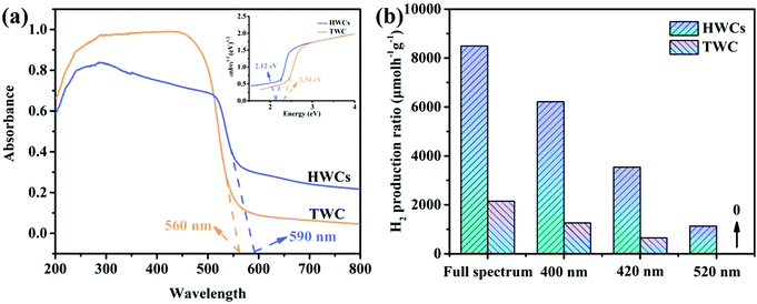
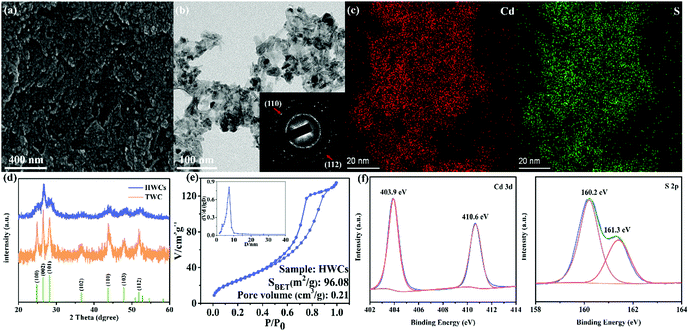
The first step in this project was to investigate the morphological structure of the HWCs. From Fig. 2a, the as-obtained HWCs look like accumulated leaves. Some nanosheets appear to be transparent (Fig. 2b) and the selected area electron diffraction (SAED) pattern (inset of Fig. 2b) demonstrated that the HWCs were polycrystalline and many crystal facets of CdS (e.g. (002), (110), (113) and (112) lattice planes) could be observed clearly. Besides, the element mapping analysis of the HWCs confirmed the uniform distribution of Cd and S elements in the nanosheets (Fig. 2c). The crystalline structures of the HWCs were studied by XRD. From Fig. 2d, the HWCs exhibit few classical hexagonal wurtzite CdS diffraction peaks (JCPDS card No. 41-1049).18 Notably, the peak intensity of the (100) and (101) facets in the HWCs was much lower than traditional wurtzite CdS (TWC), which might due to the fact that the N element in DETA could resist the formation of (100) and (101) facets.19 The porous structure of the HWCs was analyzed by N2 adsorption–desorption measurements (Fig. 2e). The HWCs showed a type IV isotherm with an evident H3 hysteresis loop, indicating the accumulated lamellar structure.20 The HWCs possessed an obviously larger specific surface area (ca. 96.08 m2 g−1) than TWC (ca. ∼6.69 m2 g−1, Fig. S1, ESI†) and a narrow pore size distribution occurred at ca.6.5 nm (inset of Fig. 2e). Thus, it may be concluded that the high surface area of the HWCs could expose more active sites and, to some extent, enhance mass transfer rate during water splitting.21 The chemical state of the HWCs was examined by XPS in Fig. 2f. The Cd 3d spectrum could be deconvoluted into two peaks at 403.9 and 410.6 eV, relating to Cd 3d5/2 and Cd 3d3/2 of Cd2+, respectively.22 The S 2p spectrum presented two peaks at 160.2 eV and 161.3 eV,23 which corresponded to S 2p3/2 and S 2p1/2 of S2− in the HWCs. So far, it can be confirmed that hexagonal wurtzite phase CdS nanoplates have been successfully constructed.In order to study the photoelectric properties of HWCs, UV-Vis diffuse reflectance spectra were carried out. From Fig. 3a, the basal absorption edge of the HWCs occurred at ca. 590 nm, which was slightly wider than TWC (ca. 560 nm). Accordingly, compared with TWC, the energy band of the HWCs was narrowed from ca. 2.31 to 2.12 eV (inset of Fig. 3a). Even though the visible-light response ability of the HWCs was improved slightly, their water splitting performance was enhanced remarkably. Just as shown in Fig. 3b, the HWCs possessed a high H2 evolution of ca. 6214.5 and 3537.8 μmol h−1 g−1 at λ ≥ 400 and 420 nm, respectively. Comparing the water splitting rate with other CdS-based photocatalysts reported previously from Table 1, it can be observed that the H2 evolution rate of the HWCs in our experiment is much higher than that of most reports and even higher than some of the Pt supported CdS samples. Besides, compared with these reports, TWC also showed an enhanced H2 production due to the solvent effect of DETA. During the fabrication of CdS, DETA can accelerate the aggregation of tiny CdS crystalline grains and improve its photoelectric properties. Additionally, in order to demonstrate the extended visible-light response ability of HWCs, the H2 evolution performances of HWCs at visible-light of λ ≥ 520 nm and full spectrum light were studied as well (ca. 1130.2 and 8495.5 μmol h−1 g−1, respectively). However, the performance of TWC was 1257.1 μmol h−1 g−1, which was only about one sixth of HWCs at λ ≥ 400 nm and there was no H2 production trace under the irradiation of λ ≥ 520 nm.
 | ||
| Fig. 3 (a) UV-visible absorbance spectrum, (b) photocatalytic H2 production activities under different light irradiation of HWCs and TWC. | ||
Furthermore, the apparent quantum yield (AQY) of HWCs could reach up to 27.1% under single wavelength light at 420 ± 10 nm. All these results provided solid evidence to demonstrate that HWCs indeed exhibit a high light utilization ability during water splitting. Generally, the enhanced H2 production related to efficient charge carrier separation.24,25
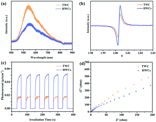
The steady-state photoluminescence (PL) quenching effect related to charge carrier transfer and recombination. Thus it is an efficient method to study the recombination rate of electron–hole pairs. As proved in Fig. 4a, the PL peak intensity of the HWCs was much lower than that of TWC at around 550 nm, indicating the inhibited charge carrier recombination and prolonged electron lifetime. The average fluorescence lifetime in HWCs was ca. 1.93 ns (Fig. S2, ESI†). Additionally, from Fig. 4b, EPR presented a higher paramagnetic signal than TWC, thereby directly confirming its excellent electron–hole pair separation ability.30 The photocurrent response was performed to study the electron generation ability of CdS. As displayed in Fig. 4c, the HWCs showed an obviously enhanced photocurrent intensity compared to TWC when the visible light source was turned on and off, which indicated that the exposed crystal facets of the HWCs could accelerate photoinduced electron and hole separation.31 The electrochemical impedance spectra (EIS) were also introduced to investigate the interfacial electron transportability of HWCs and TWC. The smaller semicircle arc radius suggested a higher charge carrier separation.32 In Fig. 4d, the HWCs presented a smaller semicircle than TWC, suggesting the lower charge transfer resistance. From the above results, it could be concluded that the exposed (110) and (112) facets in HWCs could remarkably improve their photoelectric properties.
 | ||
| Fig. 4 (a) Steady-state photoluminescence (PL) spectra, (b) electron spin resonance (EPR) spectra, (c) photocurrent response and (d) electrochemical impedance spectra (EIS) of HWCs and TWC. | ||
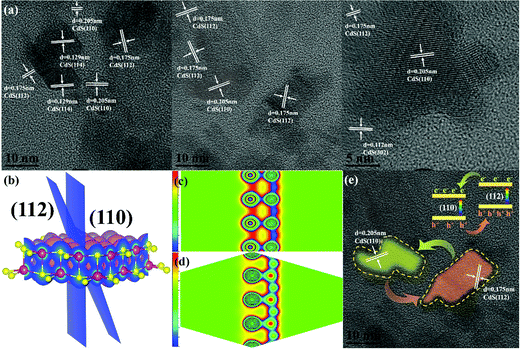
The enhanced photocatalytic efficiency of the HWCs can be ascribed to the exposed (110) and (112) crystal faces in the HWCs. HRTEM was employed to study its crystal facet structure. From Fig. 5a and Fig. S3 (ESI†), the fringe spaces in randomly selected regions were 0.205, 0.175, 0.129 and 0.112 nm, corresponding to the (110), (112), (114) and (302) lattice planes, respectively. It is worth noting that all these regions both contain abundant (110) and (112) lattice planes, inspiring us that the enhanced charge carrier separation of the HWCs was related to the exposed (110) and (112) lattice planes. To explore the electron transfer mechanism between the (110) and (112) facets of the HWCs, density functional theory (DFT) calculations were employed. From the 3D charge distribution in Fig. 5b, compared with the (112) facets, abundant charge accumulation occurred in the (110) facets. Besides, it can be observed that the charge accumulation in the (110) facets was higher than in the (112) facets (Fig. 5c and d) in the deformation charge density maps, thereby it might suggest that the (110) facets could serve as an electron reservoir during H2 evolution.
So, based on previous experiments and DFT calculation results, we proposed a possible photocatalytic mechanism for H2 production. First, to some extent, the exposed (110) and (112) facets could narrow the band gap of CdS from 2.31 to 2.12 eV (inset of Fig. 3a) and then enhance the visible-light responsibility of HWCs, which is more beneficial for generating H2 from water. Second, as shown in Fig. 5e, under visible-light irradiation, the photoexcited e− in the (112) facets would be transformed to (110) facets automatically due to its abundant charge accumulation. Meanwhile, h+ migrates in the reverse direction. Therefore, the especially exposed (112) and (110) facets significantly promoted charge separation and H2 production eventually.
4. Conclusions
In summary, HWCs with exposed (110) and (112) crystal facets have been successfully prepared. Compared with TWC, the basal absorption edge of the HWCs was extended to ca. 590 nm and the band gap of the HWCs was narrowed to ca. 2.12 eV, proving their enhanced visible-light response ability. Accordingly, the HWCs possessed a high H2 evolution of ca. 6214.5 μmol h−1 g−1, which is about six-fold higher than TWC (1257.1 μmol h−1 g−1), directly confirming the unique photoelectric ability. In addition, the DFT calculation results indicated that the charge accumulation in the (110) facets was higher than in the (112) facets. Based on the above results, a possible charge transformation mechanism of the HWCs was proposed. The photoexcited e− in the (112) facets would migrate to the (110) facets, thereby enhancing the photo-charge carrier separation process and thus H2 evolution. This work might give a new perspective for designing cocatalyst-free mono-component CdS catalysts and the specially prepared HWCs might replace noble metals as a cocatalyst in the future.Conflicts of interest
There are no conflicts to declare.Acknowledgements
This work was supported by a grant from the doctor foundation of Shandong province (No. ZR2019BB010), Qingdao Applied Basic Research Program (19-6-2-81-cg), the China Postdoctoral Science Foundation funded project (2020M672015), Shandong Key Laboratory of Reactions and Isolations of Muti-phase Liquid (2019MFRSE-B03), the Natural Science Foundation of National (NSFC21978141), the Open Project of Nankai University Key Laboratory of Advanced Energy Materials Chemistry (Ministry of Education), the special fund of Beijing Key Laboratory of Clean Fuels and Efficient Catalytic Emission Reduction Technology, and Qingdao Postdoctoral Applied Research Program.References
- C. Zhang, Y. Zhou, Y. Zhang, S. Zhao, J. Fang and X. Sheng, New J. Chem., 2017, 41, 11089–11096 RSC.
- Y. Li, X. Feng, Z. Lu, H. Yin, F. Liu and Q. Xiang, J. Colloid Interface Sci., 2018, 513, 866–876 CrossRef CAS.
- Y. Li, Z. Jin, H. Wang, Y. Zhang and H. Liu, J. Colloid Interface Sci., 2019, 537, 629–639 CrossRef CAS.
- Q. Xiang, X. Ma, D. Zhang, H. Zhou, Y. Liao, H. Zhang, S. Xu, I. Levchenko and K. Bazaka, J. Colloid Interface Sci., 2019, 556, 376–385 CrossRef CAS.
- J. Fu, Q. Xu, J. Low, C. Jiang and J. Yu, Appl. Catal., B, 2019, 243, 556–565 CrossRef CAS.
- H. Zhao, Y. Dong, P. Jiang, G. Wang, H. Miao, R. Wu, L. Kong, J. Zhang and C. Zhang, ACS Sustainable Chem. Eng., 2015, 3, 969–977 CrossRef CAS.
- Q. Xiang, J. Yu and M. Jaroniec, J. Am. Chem. Soc., 2012, 134, 6575–6578 CrossRef CAS.
- W.-K. Jo and N. C. S. Selvam, Chem. Eng. J., 2017, 317, 913–924 CrossRef CAS.
- Q. Li, B. Guo, J. Yu, J. Ran, B. Zhang, H. Yan and J. R. Gong, J. Am. Chem. Soc., 2011, 133, 10878–10884 CrossRef CAS.
- T.-D. Nguyen-Phan, S. Luo, D. Vovchok, J. Llorca, J. Graciani, J. F. Sanz, S. Sallis, W. Xu, J. Bai, L. F. J. Piper, D. E. Polyansky, E. Fujita, S. D. Senanayake, D. J. Stacchiola and J. A. Rodriguez, ACS Catal., 2016, 6, 407–417 CrossRef CAS.
- Q. Xiang, B. Cheng and J. Yu, Appl. Catal., B, 2013, 138–139, 299–303 CrossRef CAS.
- M. Liu, D. Jing, Z. Zhou and L. Guo, Nat. Commun., 2013, 4, 2278 CrossRef.
- Y. Bai, T. Chen, P. Wang, L. Wang and L. Ye, Chem. Eng. J., 2016, 304, 454–460 CrossRef CAS.
- S. Sun, P. Gao, Y. Yang, P. Yang, Y. Chen and Y. Wang, ACS Appl. Mater. Interfaces, 2016, 8, 18126–18131 CrossRef CAS.
- C. Li, L. Han, R. Liu, H. Li, S. Zhang and G. Zhang, J. Mater. Chem., 2012, 22, 23815–23820 RSC.
- S. Song, Z. Liang, W. Fu and T. Peng, ACS Appl. Mater. Interfaces, 2017, 9, 17013–17023 CrossRef CAS.
- Y. Zhang, L. Han, C. Wang, W. Wang, T. Ling, J. Yang, C. Dong, F. Lin and X.-W. Du, ACS Catal., 2017, 7, 1470–1477 CrossRef CAS.
- L. Xi, W. X. W. Tan, C. Boothroyd and Y. M. Lam, Chem. Mater., 2008, 20, 5444–5452 CrossRef CAS.
- J. Yu, Y. Yu, P. Zhou, W. Xiao and B. Cheng, Appl. Catal., B, 2014, 156-157, 184–191 CrossRef CAS.
- Y. Liu, S. Shen, J. Zhang, W. Zhong and X. Huang, Appl. Surf. Sci., 2019, 478, 762–769 CrossRef CAS.
- J. Yu, H. Yu, B. Cheng, M. Zhou and X. Zhao, J. Mol. Catal. A: Chem., 2006, 253, 112–118 CrossRef CAS.
- S. Xiong, X. Zhang and Y. Qian, Cryst. Growth Des., 2009, 9, 5259–5265 CrossRef CAS.
- X. Yao, T. Liu, X. Liu and L. Lu, Chem. Eng. J., 2014, 255, 28–39 CrossRef CAS.
- C. Zhang, Y. Zhou, J. Bao, J. Fang, S. Zhao, Y. Zhang, X. Sheng and W. Chen, Chem. Eng. J., 2018, 346, 226–237 CrossRef CAS.
- C. Zhang, Y. Zhou, J. Bao, X. Sheng, J. Fang, S. Zhao, Y. Zhang and W. Chen, ACS Appl. Mater. Interfaces, 2018, 10, 18796–18804 CrossRef CAS.
- C. C. Chan, C. C. Chang, C. H. Hsu, Y. C. Weng, K. Y. Chen, H. H. Lin, W. C. Huang and S. F. Cheng, Int. J. Hydrogen Energy, 2014, 39, 1630–1639 CrossRef CAS.
- J. Jin, J. Yu, G. Liu and P. K. Wong, J. Mater. Chem. A, 2013, 1, 10927–10934 RSC.
- N. Bao, L. Shen, T. Takata, K. Domen, A. Gupta, K. Yanagisawa and C. A. Grimes, J. Phys. Chem. C, 2007, 111, 17527–17534 CrossRef CAS.
- S. W. Cao, Y. P. Yuan, J. Fang, M. M. Shahjamali, F. Y. C. Boey, J. Barber, S. C. Joachim Loo and C. Xue, Int. J. Hydrogen Energy, 2013, 38, 1258–1266 CrossRef CAS.
- W. Xue, W. Chang, X. Hu, F. Jun and E. Liu, Chin. J. Catal., 2021, 42, 152–163 CrossRef CAS.
- C. Zhang, B. Liu, X. Cheng, Z. Guo, T. Zhuang and Z. Lv, ACS Appl. Energy Mater., 2019, 852–860 Search PubMed.
- Z. Lv, X. Cheng, B. Liu, Z. Guo and C. Zhang, Appl. Surf. Sci., 2020, 504, 144486 CrossRef CAS.
Footnote |
| † Electronic supplementary information (ESI) available. See DOI: 10.1039/d0nj04778c |
| This journal is © The Royal Society of Chemistry and the Centre National de la Recherche Scientifique 2021 |


![[greater than or equal, slant]](https://www.rsc.org/images/entities/char_2a7e.gif) 400 nm 300W Xe
400 nm 300W Xe