
 Open Access Article
 This Open Access Article is licensed under a Creative Commons Attribution-Non Commercial 3.0 Unported Licence
Boron vacancy: a strategy to boost the oxygen reduction reaction of hexagonal boron nitride nanosheet in hBN–MoS2 heterostructure†
Dipayan
Roy‡
a,
Karamjyoti
Panigrahi‡
 a,
Bikram K.
Das
b,
Uday K.
Ghorui
d,
Souvik
Bhattacharjee
b,
Madhupriya
Samanta
ac,
Sourav
Sarkar
a and
Kalyan K.
Chattopadhyay
*ab
a,
Bikram K.
Das
b,
Uday K.
Ghorui
d,
Souvik
Bhattacharjee
b,
Madhupriya
Samanta
ac,
Sourav
Sarkar
a and
Kalyan K.
Chattopadhyay
*ab
aSchool of Materials Science and Nanotechnology, Jadavpur University, Kolkata-700032, India. E-mail: kalyan_chattopadhyay@yahoo.com
bDepartment of Physics, Jadavpur University, Kolkata-700032, India
cDepartment of Electronics and Telecommunication Engineering, Jadavpur University, Kolkata 700032, India
dIndian Institute of Engineering Science and Technology, Shibpur, Howrah-711103, India
First published on 14th June 2021
Abstract
The incorporation of vacancies in a system is considered a proficient method of defect engineering in general catalytic modulation. Among two-dimensional materials, the deficiency of surface active sites and a high band gap restrict the catalytic activity of hexagonal boron nitride (hBN) material towards the oxygen reduction reaction (ORR), which hinders its applicability in fuel cells. A bane to boon strategy has been introduced here by coupling two sluggish ORR materials (hBN & MoS2) by a probe-sonication method to form a heterostructure (termed HBPS) which fosters four electron pathways to assist the reduction of oxygen. Theoretical and experimental studies suggest the kinetically and thermodynamically favorable formation of boron vacancies (B-vacancies) in the presence of MoS2, which act as active sites for oxygen adsorption in HBPS. B-vacancy induced uneven charge distribution together with band gap depression promote rapid electron transfer from the valance band to the conduction band which prevails over the kinetic limitation of pure hBN nanosheets towards ORR kinetics. The formed B-vacancy induced HBPS further exhibits a low Tafel slope (66 mV dec−1), and a high onset potential (0.80 V vs. RHE) with an unaltered electrochemically active surface area (ESCA) after long-term cycling. Thus, vacancy engineering in hBN has proved to be an efficient approach to unlock the potential of catalytic performance enhancement.
1. Introduction
Defect engineering is considered a competent skill in the catalyst field because defect induced high distortion energy and diverse atomic rearrangements significantly improve the overall performance of catalysts by providing higher active-site exposure or modulating the electronic band structure.1 A variety of defect engineering strategies, i.e., plasma treatment,2 heteroatom functionalization,3 template-based synthesis,4 controllable solvothermal growth,5 chemical etching,6etc. have been effectively utilized for achieving a desired catalytic performance. A plethora of recent reports exhibit interesting electrocatalytic activities of layered materials, such as MoS2, WS2, and MXenes which are considered two-dimensional (2D) materials “beyond graphene”.7–9 Although different protocols are extensively used to promote the reaction kinetics of layered materials, their stand-alone performance in the oxygen reduction reaction (ORR) is found to trail behind that of benchmark metallic counterparts.10 Hence, recent research has focused on the electrochemical and chemical protection of metals with atomic layers while keeping the superior electrochemical activity of the underlying metal intact. In this regard, electrically non-conducting, thermally and chemically highly stable hexagonal boron nitride (hBN) is considered to be a prominent candidate, although pristine hBN is photo-/electro-catalytically inactive due to its high band gap and insufficient active sites.11 However, manipulation of its electronic properties via orbital mixing (dz2–pz) with incorporated transition metals can largely tailor the catalytic activity of hBN.12 Theoretically, the band gap of an hBN monolayer can be significantly reduced by introducing B- and N-vacancies or impurity defects via heteroatom doping uplifting its electrocatalytic activity.13 However, most heteroatom doping approaches are restricted by high-temperature annealing or harsh reaction conditions. To avoid this processing gridlock, Patil et al. combined rGO with hBN to elucidate the synergetic advantages of a carbon network and a B–N interface. In their work, minimization of surface functional groups along with effective charge distribution in the heterostructure framework enhanced the active interface, which boosted the catalytic activity of the as-prepared heterostructure towards ORR.10 As previously mentioned, band gap engineering by vacancy formation could theoretically play a pivotal role in uplifting hBN's performance towards ORR activity; herein we have integrated MoS2 nanosheets with hBN nanosheets to investigate the catalytic activity towards ORR of the as-prepared heterostructure. Similar to hBN nanosheets, the ORR performance of few-layer MoS2 nanosheets is also hindered by two electron transfer pathways involving an inactive basal plane which can only be stimulated by fruitful defect engineering, i.e. proper surface modification,14 lower particle size,15 the development of an effective edge center16, and the incorporation of foreign elements.17–19Herein, hBN and MoS2 nanosheets are successfully integrated (HBPS) via a facile probe-sonication mediated liquid exfoliation method, as depicted in Fig. 1(a). An electrochemical study clearly manifests the superior electrocatalytic performance of exfoliated HBPS, with four electron transfer pathways compared to the toxic peroxide formation mediated two electron pathways exhibited by individually prepared hBN and MoS2 sheets from their bulk counterparts. Integration of MoS2 with the prepared hBN sheets via a prolonged sonication time largely facilitates B-vacancy formation in HBPS, which acts as an activation centre for oxygen adsorption in ORR kinetics. Further, theoretical investigations clearly demonstrate that the formation energy of a B-vacancy of pristine hBN is much higher than that of the hBN–MoS2 heterostructure (Bvac–hBN–MoS2) which is mainly attributed to MoS2 integration. Moreover, the MoS2 induced B-vacancy not only provides facile charge transfer towards oxygen, it also reduces the band gap of HBPS, enabling facile electron transfer from the valance band to the conduction band. The enhanced electron density in the conduction band accelerates the electron transfer towards the adsorbed oxygen in ORR kinetics, exhibiting favourable aspects compared to other hBN and MoS2 based composites/heterostructures (Table S7†). This strategy enables the intuitive design of highly active hBN based catalysts by tailoring their activity towards ORR via modulating the amount of B-vacancies in them. This study opens a new avenue in the development of ORR active materials from individual inactive materials.
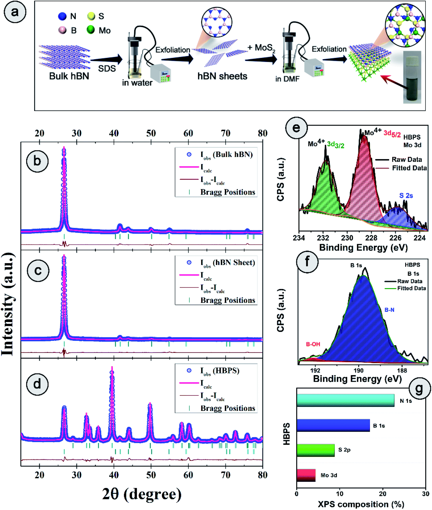 | ||
| Fig. 1 (a) Schematic of the synthesis process of the hBN–MoS2 heterostructure (HBPS). Powder X-ray diffraction patterns and associated Rietveld refinement for (b) bulk hBN, (c) hBN nanosheets, and (d) hBN–MoS2 heterostructure (HBPS). The pink curve is the best fit obtained for the experimental diffraction traces (open blue circles). The green vertical lines represent the positions of the Bragg peaks and the brown curve indicates the difference between the experimentally obtained intensities and calculated values. High resolution X-ray photoelectron spectroscopy (XPS) spectra of (e) Mo 3d and (f) B 1s. (g) Different atomic percentages of HBPS from XPS survey analysis. | ||
2. Results and discussion
2.1 Phase purity, composition, structure, and morphological investigations
The detailed synthesis procedure of the hBN sheets and HBPS has been discussed in ESI (S1 Experimental†). For clarity of synthesis, a schematic has been provided in Fig. 1(a). Details of the characterization techniques, theoretical calculations, electrochemical measurements, and other necessary calculations are provided in the Characterization section of ESI.† X-ray diffraction and Rietveld refinement (Fig. 1(b–d)) was carried out on commercial hBN powder, hBN sheets, and HBPS to determine phase purity, crystallinity, atomic positions, degree of stoichiometry, and detailed lattice parameters. For, better clarity the diffraction pattern of virgin MoS2 synthesized via probe sonication (MS) was also carried out. HBPS produced major XRD peaks at 14.39°, 39.67°, 41.72°, corresponding to the reflection planes (002), (100), (105) of 2H type MoS2, respectively (Fig. S1†). Moreover, the (002) plane originating from hBN was positioned at 2θ ∼26.74° (d 3.33 Å) in the case of HBPS, which confirms the formation of an hBN–MoS2 heterostructure. The obtained atomic occupancies (Table S1†) from the Rietveld refinement clearly reveal the presence of point defects in all three systems, viz. bulk hBN, hBN sheets, and HBPS heterostructure.20,21 From Table S1,† the estimated off-stoichiometry parameter (δ) for hB1−δN follows an incremental tendency from hBN bulk (0.0570), to hBN sheet (0.0765), to HBPS (0.2884). An MoS2 assisted prolonged sonication time triggers more point-defects in HBPS compared to hBN sheets, manifesting a large number of B-vacancies which play a pivotal role in the formation of a highly non-stoichiometric heterostructure. Thus, the boron deficiency has been significantly enhanced for hBN sheets (∼7%) from bulk counterparts (5%) and maximized in HBPS (28%). The deficiency in boron atoms commensurately inflicts a rise in the micro-strain levels of HBPS (Table S1†). Nevertheless, the stoichiometry remains unaltered for Mo and S (1![[thin space (1/6-em)]](https://www.rsc.org/images/entities/char_2009.gif) :2) in HBPS. From XPS analysis, the Mo 3d core level spectrum can be well resolved with two spin–orbit doublets corresponding to Mo4+ 3d5/2 (228.6 eV) and Mo4+ 3d3/2 (231.7 eV) of HBPS (Fig. 1(e)). Similarly, the S 2p core level spectrum was deconvoluted into two peaks positioned at S 2p3/2 (161.7 eV) and S 2p1/2 (163 eV), attributed to intrinsic sulfur.22 The absence of any peaks around 162.2 and 161.2 eV clearly nullifies any trace of the 1T phase of MoS2 in HBPS (Fig. S2†).23 In the case of B 1s (Fig. 1(f)), the major peak is observed at 189.8 eV, along with a tiny shoulder peak at 192 eV corresponding to the B–N bond and B–OH bond of hBN, respectively.10,24
:2) in HBPS. From XPS analysis, the Mo 3d core level spectrum can be well resolved with two spin–orbit doublets corresponding to Mo4+ 3d5/2 (228.6 eV) and Mo4+ 3d3/2 (231.7 eV) of HBPS (Fig. 1(e)). Similarly, the S 2p core level spectrum was deconvoluted into two peaks positioned at S 2p3/2 (161.7 eV) and S 2p1/2 (163 eV), attributed to intrinsic sulfur.22 The absence of any peaks around 162.2 and 161.2 eV clearly nullifies any trace of the 1T phase of MoS2 in HBPS (Fig. S2†).23 In the case of B 1s (Fig. 1(f)), the major peak is observed at 189.8 eV, along with a tiny shoulder peak at 192 eV corresponding to the B–N bond and B–OH bond of hBN, respectively.10,24
From XPS survey analysis, the estimated atomic percentage of boron in HBPS is quite low at 17% in comparison with the nitrogen content (22.27%) (Fig. 1(g) and S3†). As a result, the percentage of boron vacancies has become 24% for the hBN counterpart in HBPS. Thus, the type of non-stoichiometry in HBPS is well correlated with the previously discussed Rietveld refinement where the percentage of boron atoms remains almost the same in both analyses. Similarly, in the N 1s spectrum a dominant peak at 397.1 eV was observed, which is well matched with the conventional B–N bond of hBN (Fig. S2†). In addition, a small peak positioned at 394.5 eV was also detected, originating from Mo 3P3/2. The absence of any other well-resolved peak in N 1s strongly rules out any type of chemical bonding between Mo and N in the HBPS heterostructure (Tables S2 & S3†).25 Moreover, from the FT-IR study (Fig. S3†) there is a broad hump around 3300–3400 cm−1 with small peaks observed at around 1350 cm−1 and 809 cm−1 corresponding to OH group, B–N stretching, and bending vibrations of HBPS, respectively.26 Additionally, HBPS shows weak Mo–S vibrations at 469 cm−1, which confirms the presence of MoS2 in the prepared heterostructure (Fig. S3b†).27 The presence of the B–O bond infers the functionalization of exfoliated hBN sheets with the negatively charged hydroxyl group due to prolonged sonication in an aqueous dispersion of sodium cholate. High chemical potential induced sodium and hydroxyl ions facilitate their adsorption into the interlayer space of hBN, diminishing the interlayer interaction. This synergetic effect accelerates the self-curling process to a great extent, which in turn boosts the exfoliation of the bulk counterpart into sheets.28 Fig. S4† shows the formation of ultrathin hBN nanosheets with rough and distorted edges induced by the surface adsorbed OH−.29 In contrast to MoS2, it should be noted that MoS2 nanosheets undergo a self-assembled mechanism into a sphere or flower-like morphology by tuning the concentration and temperature of the raw precursor.30 However, the FESEM images of HBPS reveal thick MoS2 sheets rather than a flower-type morphology. The inhomogeneous distribution of the few distorted layers of hBN sheets decorated on the surface of the MoS2 sheets is shown in Fig. S5.† Elemental mapping via EDX clearly validates our aforementioned conclusion of hBN sheet decoration on exfoliated MoS2 nanosheets (Fig. S5†). Further insight into the morphology and lattice parameters was gained from high resolution transmission electron microscopy (HRTEM) analysis. The low magnification image (Fig. S6†) exhibits the ultralow thickness of the synthesized hBN sheets. The average lateral size of those sheets is around 156 nm per nanosheet (calculated with Image J software).
The clear lattice fringe pattern of the synthesized hBN was also captured using high magnification which was further processed using an Inverse Fast Fourier Transform (IFFT) by Image J to measure the actual inter-planar distance more accurately. The calculated inter-planar distance is 3.3 Å corresponding to the (002) plane of the hBN sheet (Fig. S6†). Fig. 2(a) elucidates the TEM image of HBPS where the ultrathin hBN sheets is decorated on relatively large MoS2 sheets. Lattice fringes with an interplanar spacing of 0.61 nm are well matched with the (002) plane of MoS2 (Fig. 2(b)) in HBPS. Moreover, IFFT analysis (Fig. 2(d) and (g)) of the HRTEM images was carried out via Image J software to obtain an accurate lattice spacing. The calculated d values are 0.26 nm and 0.33 nm which are well matched with the (103) plane of MoS2 and the (002) plane of hBN, respectively, of HBPS (Fig. 2(e) and (h)). Thus, the lattice spacing of hBN and MoS2 remains unaltered with respect to XRD analysis in the formation of the HBPS heterostructure.
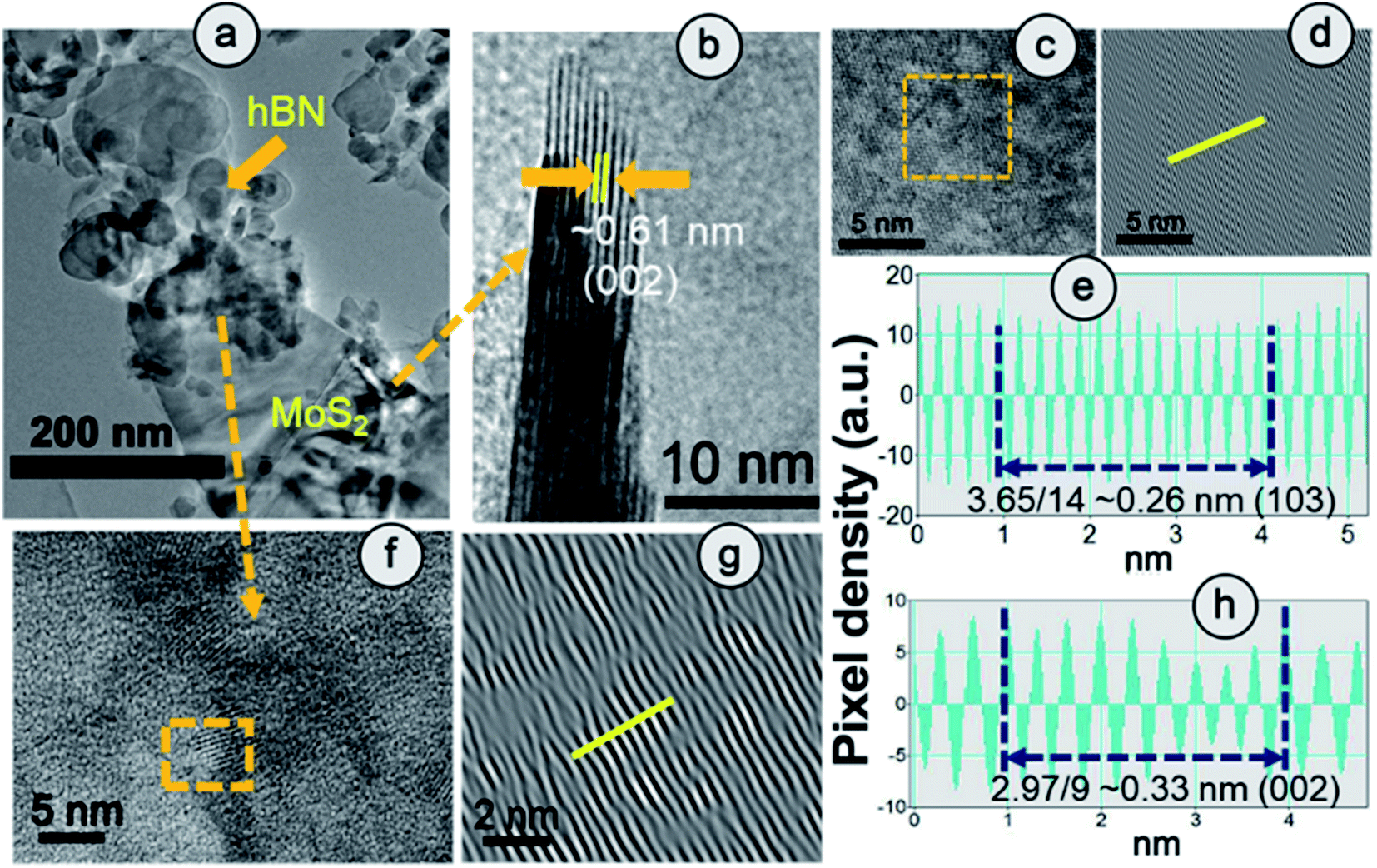 | ||
| Fig. 2 (a) HRTEM image and fringe pattern corresponding to (b) (002) and (c and d) (103) planes of MoS2. (e) IFFT analysis of the (103) plane of the MoS2 counterpart in HBPS. (f–h) Fringe pattern and IIFT analysis of the (002) plane of the hBN counterpart in HBPS. | ||
Raman spectra suggest the in-plane E2g mode of MoS2 in HBPS is positioned at 384 cm−1 with an energy separation of 24.7 cm−1 from the out-of-plane A1g mode, which implies a diminution in layer number as well as shrinkage in the interlayer coupling compared to bulk MoS2 (Fig. 3(a)). The observed redshift (1.3 cm−1) of the A1g mode in HBPS (408.7 cm−1) compared to the A1g mode of pristine MoS2 (MS) (410.12 cm−1) further confirms a synergistic interaction between hBN and MoS2 (Fig. 3(b)). Notably, the lack of characteristic peaks (J1, J2, and J3) at 150 cm−1, 219 cm−1, and 327 cm−1 confirms that the exfoliated MoS2 are of purely 2H form instead of metallic 1T phase.23 Thus, in the case of HBPS the coulombic force predominates over interlayer coupling, resulting in a shrinkage in the separation of E2g and A1g phonons to 24.7 cm−1, whereas in MS both the aforementioned factors play their stipulated role in preserving the separation at 26 cm−1. A Raman mode (E2g) of hBN was also observed in HBPS at around 1365–66 cm−1. Compared to the heterostructure, a blue shift in the E2g mode has been determined at 1374 cm−1 for the hBN sheet.7 The significant blue shift is mainly due to the distorted surface and thinness of the hBN sheet (Fig. 3(c)).31 Photoluminescence (PL) measurement indicates two broad emission peaks centered at 308 nm (4 eV) and 383 (3.32 eV) under 232 nm excitation from the exfoliated hBN sheets, which are well corroborated by previous reports.32,33
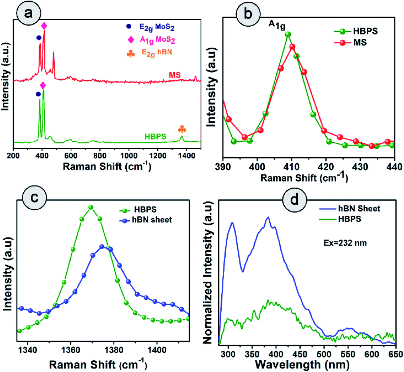 | ||
| Fig. 3 Raman spectra of (a) HBPS and hBN sheets under a 532 nm laser source. (b) Raman shift of A1g of HBPS compared to MS. (c) Shift in the peak position of the E2g mode of the hBN site of the hBN sheet and HBPS. (d) Photoluminescence (PL) spectra of the hBN sheet and HBPS under excitation at 232 nm. | ||
However, significant PL quenching was observed in the case of HBPS (Fig. 3(d)). The PL quenching phenomenon and Raman analysis clearly confirm a strong interaction between hBN and MoS2 in HBPS.34,35
2.2 Electrochemical performance study
The ORR catalytic activity of pristine hBN, MoS2, and hBN–MoS2 heterostructures (HBPS) were investigated via comparative cyclic voltammograms in O2 saturated 0.1 M KOH solution at a sweep rate of 10 mV s−1. Generally, in the case of MoS2 there are two reduction peaks at −0.790 V and −0.047 V vs. Ag/AgCl, which implies two steps in the two electron reduction process.36 The positive shift of these two reduction peaks implies facile ORR activity. In our study, the intense cathodic ORR peak (EORR) is positioned at −0.280 V vs. Ag/AgCl (0.625 V vs. RHE) for HBPS which is 127 mV and 102 mV more positive compared to MS (−0.407 V vs. Ag/AgCl, 0.49 V vs. RHE) and hBN sheets (−0.3835 V vs. Ag/AgCl, 0.52 V vs. RHE) respectively (Fig. 4(a)). The second reduction peak (in HBPS) was positioned at −0.6 V vs. Ag/AgCl which is 200 mV more positive than MS. Additionally, with the positive shift in EORR, the corresponding current density is increased (0.34 mA cm−2) compared to MS (0.16 mA cm−2) and hBN sheets (0.24 mA cm−2), indicating the efficacy of HBPS over the individual pristine materials and previous MoS2 based catalysts (Table S7†). Fig. S7† suggests an EORR of −0.16 V vs. Ag/AgCl (0.745 vs. RHE) for 20% Pt/C, which is 120 mV more positive than that of HBPS. Previously, Khan et al. observed a 50 mV shift in EORR due to sodium cholate mediated hBN (EORR ∼ −0.59 V vs. SCE or ∼ −0.635 V vs. Ag/AgCl) compared to a pristine hBN sheet (EORR ∼ −1.09 V vs. SCE or ∼ −0.635 V vs. Ag/AgCl) although in both cases the ORR pathway follows a two electron transfer process.37 Here, the prepared hBN sheet exhibits more positive EORR reduction potential (−0.383 V vs. Ag/AgCl) than in previous literature, confirming the contribution of the surfactant in the hBN sheet towards oxygen reduction kinetics. However, the observed EORR of the hBN sheet is not sufficiently positive to show efficient catalytic performance towards oxygen reduction in comparison with HBPS or 20% Pt/C. Further ORR activities were studied through linear sweep voltammograms (LSVs) at 1600 rpm using the rotating disk electrode technique (RDE) (Fig. 4(b)). The variation in the LSVs with different rotation speeds are shown in Fig. S8.† HBPS exhibits a quite similar onset potential (Eonset) (∼0.80 V vs. RHE) to the commercial electrocatalyst 20% Pt/C (∼0.82 V vs. RHE). The Eonset follows a gradually decreasing tendency from HBPS to hBN sheets (0.65 V vs. RHE) and MS (0.60 V vs. RHE) (Fig. S7†). Additionally, a significant shift towards a positive potential from the hBN sheet (0.51 vs. RHE) to HBPS (0.60 V vs. RHE) of the half-wave potential (E1/2) is observed. Moreover, the limiting-diffusion current density (JL) at 1600 rpm is drastically truncated for the hBN sheet (1.8 mA cm−2) and MS (2.5 mA cm−2), compared to the 3.6 mA cm−2 of HBPS at −0.8 V vs. Ag/AgCl. It is obvious that the inactive basal plane and low conductivity of MoS2 inhibit the electrochemical performance to a great extent.38 In our investigation, a less positive EORR and Eonset and a lower JL make MS a poor electrocatalyst for ORR kinetics. The demonstrated linear fitting of the Koutecky–Levich (K–L) plots of all the synthesized samples at different potentials reveals 1st order reaction kinetics (Fig. S8 & S9†). Thus, in Fig. 4(c), the variations in electron transfer number (n) within the potential range (−0.9 to −0.4 V) are depicted, which further confirms the ability of HBPS to perform efficient catalysis by constantly following four electron pathways. The top-notch kinetic behavior of HBPS was similarly illustrated by the quite low Tafel slope (66 mV dec−1) which is analogous to 20% Pt/C (61 mV dec−1) but lower than for other prepared materials (Fig. 4(d) and Table S4†). In HBPS the observed kinetic current density (Jk) was 7.52 mA cm−2 where it was reduced to 4.47 mA cm−2 and 3.34 mA cm−2 at −0.9 V vs. Ag/AgCl for the hBN sheet and MS, respectively (Fig. 4(e)). Fig. S10† shows the rotating-ring disk electrode (RRDE) measurements which illustrate the negligible (12–15%) formation of OH2− for HBPS in the potential range from −0.8 V to −0.2 V (vs. Ag/AgCl); in comparison, the H2O2 yield was 65–75% for the bhBN sheet.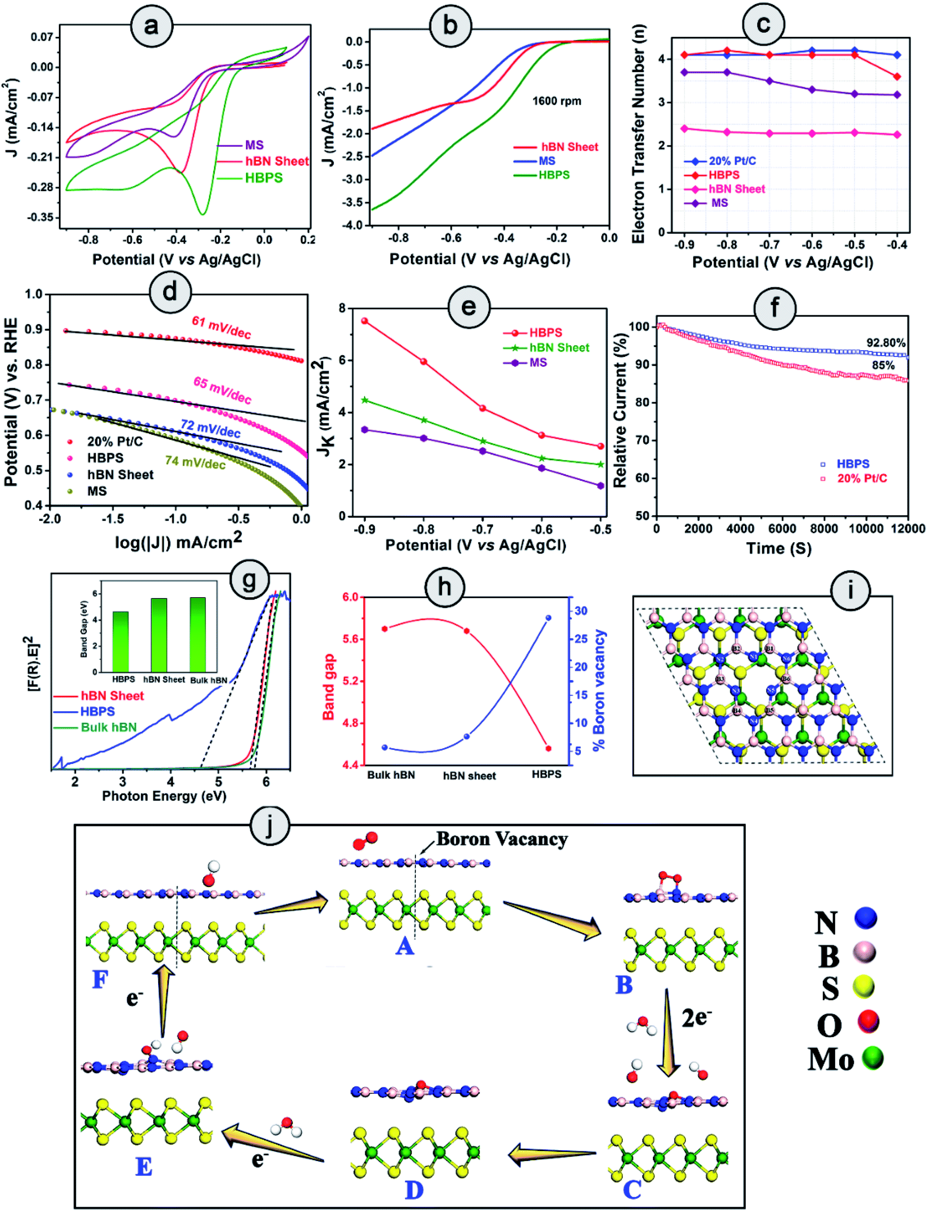 | ||
| Fig. 4 HBPS, MS and hBN sheet in an O2 saturated solution in 0.1 (M) KOH at a 10 mV s−1 scan rate: (a) cyclic voltammogram and (b) linear sweep voltammogram at 1600 rpm via a rotating disk electrode (RDE). (c) Electron transfer number (n) from RDE measurement in the potential range −0.9 to −0.4 V (vs. Ag/AgCl). (d) Tafel plots of 20% Pt/C, HBPS, MS, hBN sheet. (e) Variation in kinetic current density (Jk) in the potential range −0.9 V to −0.5 V (vs. Ag/AgCl) of HBPS, hBN sheet, and MS. (f) Chronoamperometry measurement of 20% Pt/C and HBPS in O2 saturated 0.1 (M) KOH at −0.3 V vs. Ag/AgCl under 1600 rpm for 12000 s. (g) Tauc plots of bulk hBN, hBN sheet, HBPS. (The inset shows the difference in the band gap.) (h) Correlation of boron vacancies on hBN with band gap. (i) Top view of Bvac–hBN–MoS2. (j) Mechanism of the ORR pathway of Bvac–hBN–MoS2 from DFT analysis. | ||
From RRDE analysis, the corresponding electron transfer numbers (n) of the hBN sheet and HBPS have been evaluated to be two and four electron transfer pathways, respectively, which is consistent with prior RDE analysis. The BET surface area of HBPS and the hBN sheet have been determined to have values of 99.383 m2 g−1 and 33.350 m2 g−1, respectively. It is obvious that an exfoliated MoS2 nanosheet exhibits a quite low surface area of 8.6 m2 g−1.39 The pore diameter of the hBN sheet and HBPS are quite comparable at 3.5 nm and 3.2 nm, respectively, indicating the mesoporous nature of both the prepared samples (Fig. S11†). Generally, a large surface area and pore diameter have a better probability of acting as surface-active sites for oxygen adsorption. However, here the larger pore size of the hBN sheet in comparison with HBPS reveals that the surface area and pore diameter do not play major roles in the ORR activity of the as-prepared materials. The ultrasonic treatment, i.e. cavitation, modulates the shear force, pressure, and temperature and enhances the rate of exfoliation of the layered materials in solvents. In addition, cavitation induced structural defects, and surface modification of the basal plane via B–OH bond formation promotes the separation of layers from the bulk hBN counterpart.40,41 The OH functionalization weakens the B–N double bonds (due to pπ–pπ overlap) converting those bonds into single bonds. The polarity of the formed bonds particularly increases due to the presence of surrounding electronegative nitrogen and an OH group. As a result, a long ultrasonication time induces boron vacancies or defects from the surface of the hBN sheet. Our Rietveld analyses suggest that boron deficiency is significantly enhanced for the hBN sheets (∼7%) from bulk counterparts after ultrasonication. However, in the presence of MoS2, a van der Waals type interaction occurs rather than covalent bond formation between hBN and the MoS2 sheet in HBPS, which has been confirmed by multiple spectroscopic investigations, i.e. XPS, Raman, and PL scrutiny. The shift in the A1g of MoS2 from the bulk counterpart clearly confirms the interactions between two nanosheets. Furthermore, PL quenching of HBPS under 232 nm excitation indicates some charge transfer between two sheets (as no bond or complex formation occurs). Inter-sheet van der Waals interaction and charge transfer between hBN & MoS2 shrinks the B–N bond strength and enhances the rate of B-vacancy formation under prolonged ultrasonication. Computational investigations were further carried out to understand the role of MoS2 in B-vacancy formation in HBPS.
2.3 Theoretical validation of electrochemical investigations
The aforementioned details of oxygen reduction activity clearly indicate the superior performance of HBPS compared to the other materials. It is evident that the formed B-vacancies play a pivotal role in ORR performance enhancement. To elucidate the effect of MoS2 in B-vacancy formation, density functional theory (DFT) calculations were performed. The lower formation energy (1.96 eV) of a B-vacancy in the hBN–MoS2 heterostructure system (Bvac–hBN–MoS2) compared to that of an hBN monolayer (2.49 eV) clearly confirms that MoS2 assisted the promotion of B-vacancy formation (via charge transfer and van der Waals interaction) in the hBN monolayer. Minimization of the prerequisite activation energy of oxygen for ORR to produce an upsurge in material performance can be achieved by prompting vacancy formation or band gap depreciation, which uplifts the electronic transition from the valance band to the conduction band.42 In a similar fashion, Ferrari et al. show how physical line defects (PLD) modulate the band gap of inert 2D-hBN sheets (from insulating to semiconducting) and modify the inactive surface to become electrochemically active in nature.43 To understand the effect of formed B-vacancies on the band gap of prepared materials, the band gap was estimated from the Tauc's plot, approximating the Kubelka–Munk function (Fig. 4(g)). As exhibited (Fig. 4(h)), the band gap follows a completely opposite trend to the increase in B-vacancies (previously estimated from the Rietveld refinement). Moreover, the band gap of HBPS (4.56 eV) is lower than that of both bulk hBN sheet (5.7 eV) and prepared hBN sheet (5.66 eV). From first principles calculations, the band gaps were found to be 4.56 eV, 1.59 eV, 1.66 eV, and 1.45 eV for pristine h-BN, pristine MoS2, hBN–MoS2 heterostructure, and an hBN–MoS2 heterostructure system with boron vacancies (Bvac–hBN–MoS2), respectively (Fig. S12†). It is evident from the DFT, that the formed B- vacancy reduces the band gap of the hBN–MoS2 system along with the formation of a defect band just below the conduction band, empowering swift electron transfer from the valance band to the conduction band. Fig. 4(i) illustrates a top view of Bvac–hBN–MoS2.Normally, B-vacancy formation in hBN not only reduces the band gap but also facilitates charge transfer and interaction with different transition metals, activating/amplifying the catalytic efficiency of hBN towards ORR.19,44–47 Recently, it has been shown that edge and basal plane defects enhance the electroactive area of the hBN surface and promote the boosting of the current density and recyclability of the hydrogen evolution reaction (HER).48 We also carried out Bader charge analysis to investigate the effect of vacancy formation on the charge distribution in the systems considered. All the calculated amounts of charge transferred to or from the atoms (Bader partial charge value) corresponding to the marked neighbouring atoms are documented in Table S6 and Fig. S13.† From Table S6,† it is obvious that the incorporation of a boron vacancy largely reduces the charge transfer to the three nearest-neighbour (NN) nitrogen atoms (N1, N3, N5) by ∼0.5 e in both the free-standing hBN monolayer and the Bvac–hBN–MoS2 heterostructure system (Fig. S13 & Table S6†). This B-vacancy induced non-uniform charge distribution in NN atoms of Bvac–hBN–MoS2 enhances its specific activity towards ORR, while the uniform charge distribution in B-vacancy-free hBN–MoS2 diminishes the catalytic activity. Undoubtedly, the possibility of B-vacancy formation is much higher in the hBN–MoS2 heterostructure compared to freestanding hBN sheets, and the redistribution of charge on the atoms near the boron vacancy modulates the otherwise inert composite system into an efficient host for O2 adsorption and subsequent oxygen reduction process on the vacant site.
To elucidate the effect of B-vacancy in the hBN–MoS2 heterostructure towards the ORR mechanism, further DFT analysis was performed. Initially, we carried out a first principles calculation on the defect-free hBN–MoS2 heterostructure system to study its activity towards ORR in an alkaline medium. In the first step, O2 was weakly adsorbed on the heterostructure in side-on mode which was followed by the first electron transfer process and the spontaneous breakage of one H2O molecule into H+ and OH− ions. But in the next step, via an electron and proton transfer coupling process, HO2− was formed spontaneously, indicating less efficient two-electron pathway (Fig. S14†) based ORR by the defect-free hBN–MoS2 heterostructure. O2 adsorption on a pure hBN–MoS2 system is highly endothermic in nature with an adsorption energy value of 2.10 eV. Such a brittle O2 adsorption process usually leads to peroxide ion formation after first protonation via the two-electron pathway. The protonation process was checked by placing the H atom on each of the non-equivalent O atoms one by one and the formation of an HO2− ion was observed to be the energetically most favorable reaction pathway. Further, we created about 4% B-vacancies (see ESI† for details) in the heterostructure, in line with the experiment, and studied the ORR mechanisms step by step on the Bvac–hBN–MoS2 heterostructure. At first, the O2 molecule is strongly adsorbed by Bvac–hBN–MoS2 unlike the defect-free system (“B” in Fig. 4(j) and S15†). The O2 adsorption process on the hBN–MoS2 system with boron vacancies was observed to be exothermic in nature with an energy of −0.27 eV, opposite to that on the pure hBN–MoS2 system. A lower adsorption energy corresponds to stronger adsorption of oxygen molecules towards the active site. In the next step, the breakage of the H–OH bond and subsequent adsorption of the H+ ion onto one of the O atoms occurred spontaneously by completely dissociating the di-oxygen (O–O) bond, and hence eradicating the possibility of ORR proceeding through the two-electron pathway (Fig. 4(j) and S16†). Considering the free energy of the final product of ORR via an alkaline medium, i.e., Bvac–hBN–MoS2 and four free hydroxyl ions as a reference, the free energy difference of each ORR intermediate (OOH*, OH*, O*) was calculated. The free energy difference of the first step (ΔG1) was calculated to be 3.26 eV (Fig. S16†). In the next step, i.e., the second electron transfer process, the hydroxyl radical (OH*) got detached from the surface, taking one electron and spontaneously forming a free hydroxyl ion with a free energy difference (ΔG2) of −0.02 eV, substantiating the progress of Bvac–hBN–MoS2via an energetically efficient four electron pathway unlike the defect-free system (Fig. S15† & “C” of Fig. 4(j)). As the OH− was formed, the other O atom remained strongly adsorbed on the surface in epoxy formation, as indicated by the exergonic value of the free energy difference of this step (“D” in Fig. 4(j) and S15†). In the next step, after complete dissociation of another water molecule into H+ and OH−, the formed H+ gets adsorbed onto the O atom on the catalyst surface (“E” of Fig. 4(j) and S15†). A small endothermic reaction barrier was observed in the aforementioned facile step (OH* from O*) with a free energy difference value of 0.72 eV since the single O molecule was strongly adsorbed on the catalyst surface in the preceding step. From the above discussion, the breaking of the di-oxygen bond and simultaneous formation of the free OH− ion was concluded to be a key electrochemical step for ORR kinetics exhibited by Bvac–hBN–MoS2. The final electron transfer step proceeded spontaneously with the desorption of the hydroxyl ion from the surface (“F” of Fig. 4(j)). However, the active site and electrochemically active surface area (ESCA) evaluation are also essential parameters to evaluate the performance of electrocatalysis.
2.4 Active sites and durability investigations
From Fig. 5(a–c), the CVs in the non-faradaic regions at different scan rates were first carried out and the double layer capacitance (Cdl) and ESCA were evaluated (details are provided in ESI†). The double-layer capacitance (Cdl) is a maximum in the case of HBPS (12.3 mF cm−2) where it gradually decreases to 9.8 mF cm−2 and 3.1 mF cm−2 for the hBN sheet and MS, respectively (Fig. 5(d)). As Cdl is directly proportional to ESCA, the higher Cdl and ESCA of HBPS indicate the formation of maximum active sites. Besides activity and selectivity, durability is a vital parameter for evaluating the ORR performance of electrocatalysts. Thus, the ORR stability of HBPS was evaluated following the chronoamperometric protocol. Fig. 5(f) shows that the retention of relative current density is much higher in HBPS (92.80%) than in 20% Pt/C (85%) after 12000 s. To support the excellent durability of HBPS, Cdl and ESCA were also calculated after 12000 s by taking CVs in the same potential window (Fig. 5(e–h)). The calculated ESCA, Cdl, and JL of HBPS all show minor degradation from the initial values after long-term durability tests (Fig. 5(h) and Table S5†). The LSV of HBPS shows a negligible 3 mV degradation in E1/2 as well as in JL after 2000 cycles (Fig. 5(i)). In addition to ESCA and long cyclic stability, tolerance towards methanol is also a vital parameter for developing electrocatalysts, as methanol and its intermediates can poison the active sites of catalysts through equilibrium loss in the electrode materials. This ruinous effect drastically decreases the energy density and increases the overpotential of the cathodic reactions, restricting its overall electrochemical utilization rate.49 HBPS exhibited admirable tolerance toward the methanol poisoning effect compared to a commercial 20% Pt/C electrode during chronoamperometric measurements (Fig. S17†) when 2 M methanol (20 volume%) was injected into O2 saturated 0.1 M KOH solution after 400 s. Only a 4% change was observed in the relative current of HBPS compared to a 14% change in 20% Pt/C, which proves its efficacy in methanol tolerance compared to 20% Pt/C. Thus, a Bvac–hBN–MoS2 heterostructure can carry out ORR in an alkaline medium in the energetically efficient four electron pathway without forming any hazardous final product like peroxide ions in contrast to the defect-free system.
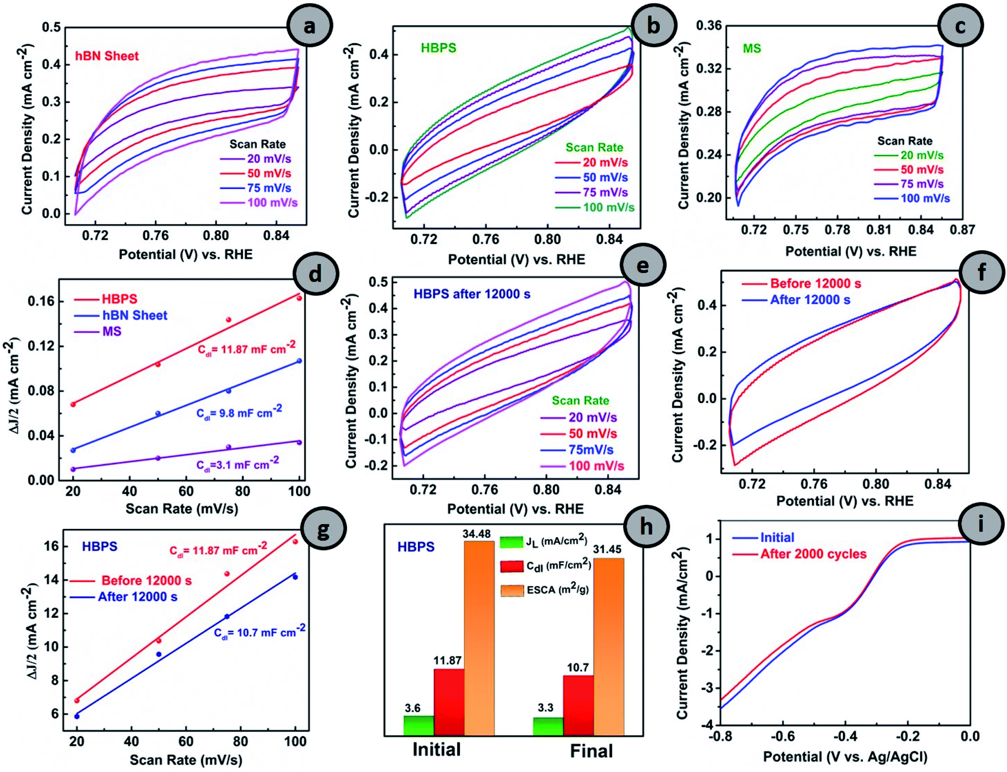 | ||
| Fig. 5 Cyclic voltammograms of (a) hBN sheet, (b) HBPS and (c) MS in the non-faradaic region with scan rates 20 mV s−1 to 100 mV s−1. (d) Plot of ΔJ/2 vs. scan rates for the determination of Cdl of hBN sheet, HBPS, and MS. Cyclic voltammograms (CV) of (e) HBPS at scan rates of 20 mV s−1 to 100 mV s−1 after a durability test. (f) Comparison of CV at 100 mV s−1. (g) Plot of ΔJ/2 vs. scan rates. (h) Determination of Cdl, JL and ESCA for HBPS before and after a durability test of HBPS. (i) LSV measurement of HBPS at a scan rate 10 mV s−1 in 0.1 (M) KOH at 1600 rpm initially and after 2000 cycles. | ||
3. Conclusions
In a nutshell, vacancy engineering in the sluggish ORR material hBN, by integrating it with MoS2via a liquid exfoliation method, effectively boosts the catalytic activity of the formed heterostructure HBPS, enhancing the intrinsic formation of B-vacancies within it. The electronic and geometric structure of hBN with the support of MoS2, including B-vacancies on the basal plane of hBN, serves most catalytic active sites for ORR activity by a quick electron transfer from the valance band to the conduction band owing to band gap minimization of the formed heterostructure. The experimentally realized work is well corroborated by the theoretical predictions which were carried out. The corresponding superior ORR performance of HBPS is harvested with a large kinetic current density (5.96 mA cm−2 at 0.1 V vs. RHE) and reduction potential (EORR) (0.63 V vs. RHE), along with a smaller Tafel slope (66 mV dec−1) as well as four electron pathway selectivity. Additionally, the long-term durability (92.80%) and lower tolerance to methanol corrosion of the prepared HBPS heterostructure suggest the inclusive applicability of the potential of the aforementioned vacancy engineering to develop cost-effective and durable hBN–MoS2 based catalysts.Conflicts of interest
The authors declare no competing financial interest.Acknowledgements
The authors DR and SS wish to acknowledge and thank the Science & Engineering Research Board (SERB), a statutory body of Department of Science & Technology (DST), Government of India (File No. EEQ/2018/001127) for providing financial support. The author KP wishes to thank Council of Scientific and Industrial Research (CSIR) for providing him a senior research fellowship (File No. 09/096 (0880)/2017-EMR-I). One of the authors, BKD, would like to thank the Department of Science & Technology (DST Inspire- IF150499). SB [File No. 09/096(0946)/2018-EMR-I] heartily acknowledges the Council of Scientific and Industrial Research (CSIR), the Government of India for awarding a fellowship during the execution of this work. Authors also wish to acknowledge Irfan Masood for his generous help in materials preparation.References
- X. Wang, Y. Zhang, H. Si, Q. Zhang, J. Wu, L. Gao, X. Wei, Y. Sun, Q. Liao, Z. Zhang and K. Ammarah, J. Am. Chem. Soc., 2020, 142, 4298–4308 CrossRef CAS PubMed.
- R. Mohan, A. Modak and A. Schechter, ACS Appl. Energy Mater., 2021, 4, 564–594 CrossRef CAS.
- D. Roy, S. Sarkar, K. Bhattacharjee, K. Panigrahi, B. K. Das, K. Sardar, S. Sarkar and K. K. Chattopadhyay, Carbon, 2020, 166, 361–373 CrossRef CAS.
- Y. Mun, S. Lee, K. Kim, S. Kim, S. Lee, J. W. Han and J. Lee, J. Am. Chem. Soc., 2019, 141, 6254–6262 CrossRef CAS PubMed.
- Q. Zhang, N. M. Bedford, J. Pan, X. Lu and R. A. Amal, Adv. Energy Mater., 2019, 9, 1901312–1901325 CrossRef.
- S. Dou, L. Tao, J. Huo, S. Wang and L. Dai, Energy Environ. Sci., 2016, 9, 1320–1326 RSC.
- Y. Lin, T. V. Williams and J. W. Connell, J. Phys. Chem. Lett., 2010, 1, 277–283 CrossRef CAS.
- M. Chhowalla, H. S. Shin, G. Eda, L. J. Li, K. P. Loh and H. Zhang, Nat. Chem., 2013, 5, 263–275 CrossRef.
- Q. Xue, Z. Pei, Y. Huang, M. Zhu, Z. Tang, H. Li, Y. Huang, N. Li, H. Zhang and C. Zhi, J. Mater. Chem. A, 2017, 5, 20818–20823 RSC.
- P. K. Rastogi, K. R. Sahoo, P. Thakur, R. Sharma, S. Bawari, R. Podila and T. N. Narayanan, Phys. Chem. Chem. Phys., 2019, 21, 3942–3953 RSC.
- I. M. Patil, M. Lokanathan and B. Kakade, J. Mater. Chem. A, 2016, 4, 4506–4515 RSC.
- K. Uosaki, G. Elumalai, H. Noguchi, T. Masuda, A. Lyalin, A. Nakayama and T. Taketsugu, J. Am. Chem. Soc., 2014, 136, 6542–6545 CrossRef CAS PubMed.
- S. Back and S. Siahrostami, Nanoscale Adv., 2019, 1, 132–139 RSC.
- X. Chia, A. Y. S Eng, A. Ambrosi, S. M. Tan and M. Pumera, Chem. Rev., 2015, 115, 11941–11966 CrossRef CAS.
- T. Wang, D. Gao, J. Zhuo, Z. Zhu, P. Papakonstantinou, Y. Li and M. Li, Chem.–Eur. J., 2013, 19, 11939–11948 CrossRef CAS.
- S. Jayabal, G. Saranya, J. Wu, Y. Liu, D. Geng and X. Meng, J. Mater. Chem. A, 2017, 5, 24540–24563 RSC.
- I. J Gomez, B. Arnaiz, M. Cacioppo, F. Arcudi and M. Prato, J. Mater. Chem. B, 2018, 6, 5540–5548 RSC.
- J. Mao, P. Liu, C. Du, D. Liang, J. Yan and W. Song, J. Mater. Chem. A, 2019, 7, 8785–8789 RSC.
- K. Gopalakrishnan, K. Pramoda, U. Maitra, U. Mahima, M. A. Shah and C. N. R. Rao, Nanomater. Energy, 2015, 4, 9–17 CrossRef.
- Y. I. Kim, J. K. Jung, K. S. Ryu, S. H. Nahm and D. H. Gregory, J. Phys. D: Appl. Phys., 2005, 38, 1127–1131 CrossRef CAS.
- M. Ramos, F. Galindo-Hernández, I. Arslan, T. Sanders and J. M. Domínguez, Sci. Rep., 2017, 7, 12322–12331 CrossRef PubMed.
- A. Syari'Ati, S. Kumar, A. Zahid, A. Ali El Yumin, J. Ye and P. Rudolf, Chem. Commun., 2019, 55, 10384–10387 RSC.
- L. Jiang, S. Zhang, S. A Kulinich, X. Song, J. Zhu, X. Wang and H. Zeng, Mater. Res. Lett., 2015, 3, 177–183 CrossRef CAS.
- S. Saha, M. Jana, P. Khanra, P. Samanta, H. Koo, N. C Murmu and T. Kuila, ACS Appl. Mater. Interfaces, 2015, 7, 14211–14222 CrossRef CAS PubMed.
- C. Wu, D. Liu, H. Li and J. Li, Small, 2018, 14, 1704227–1704237 CrossRef PubMed.
- P. M. Sudeep, S. Vinod, S. Ozden, R. Sruthi, A. Kukovecz, Z. Konya, R. Vajtai, M. R. Anantharaman, P. M. Ajayan and T. N. Narayanan, RSC Adv., 2015, 5, 93964–93968 RSC.
- D. Gao, M. Si, J. Li, J. Zhang, Z. Zhang, Z. Yang and D. Xue, Nanoscale Res. Lett., 2013, 8, 129–137 CrossRef PubMed.
- X. Li, X. Hao, M. Zhao, Y. Wu, J. Yang, Y. Tian and G. Qian, Adv. Mater., 2013, 25, 2200–2204 CrossRef CAS PubMed.
- Z. Cui, A. J. Oyer, A. J. Glover, H. C. Schniepp and D. H. Adamson, Small, 2014, 10, 2352–2355 CrossRef CAS PubMed.
- X. Zheng, Y. Zhu, Y. Sun and Q. Jiao, J. Power Sources, 2018, 395, 318–327 CrossRef CAS.
- Y. Chen, K. Li, Z. Li, S. Hu, X. Sun, Z. Shi, X. Liu and D. Li, J. Alloys Compd., 2019, 797, 262–268 CrossRef CAS.
- D. Lee and S. H. Song, RSC Adv., 2017, 7, 7831–7835 RSC.
- L. Museur, E. Feldbach and A. Kanaev, Phys. Rev. B: Condens. Matter Mater. Phys., 2008, 78, 155204–155212 CrossRef.
- L. P. L. Mawlong, A. Bora and P. K. Giri, Sci. Rep., 2019, 9, 19414–19427 CrossRef PubMed.
- J. Yuan, S. Najmaei, Z. Zhang, J. Zhang, S. Lei, P. M. Ajayan, B. I. Yakobson and J. Lou, ACS Nano, 2015, 9, 555–563 CrossRef CAS PubMed.
- T. Wang, D. Gao, J. Zhuo, Z. Zhu, P. Papakonstantinou, Y. Li and M. Li, Chem.–Eur. J., 2013, 19, 11939–11948 CrossRef CAS PubMed.
- A. F Khan, M. P Down, G. C. Smith, C. W. Foster and C. W. Banks, J. Mater. Chem. A, 2017, 5, 4103–4113 RSC.
- A. P. Tiwari, Y. Yoon, T. G. Novak, A. Azam, M. Lee, S. S. Lee, S. G. Lee, D. J. Srolovitz, K. An and S. Jeon, Adv. Mater. Interfaces, 2019, 6, 1900948–1900957 CrossRef CAS.
- R. Wang, S. Gao, K. Wang, M. Zhou, S. Cheng and K. Jiang, Sci. Rep., 2017, 7, 1–9 CrossRef PubMed.
- Y. Lin, T. V. Williams, T. B. Xu, W. Cao, H. E. Elsayed-Ali and J. W. Connell, J. Phys. Chem. C, 2011, 115, 2679–2685 CrossRef CAS.
- J. Ren, L. Stagi, C. M. Carbonaro, L. Malfatti, M. F. Casula, P. C. Ricci, A. E. D. R. Castillo, F. Bonaccorso, L. Calvillo, G. Granozzi and P. Innocenzi, 2D Materials, 2020, 7, 045023–045036 CrossRef CAS.
- H. Liu, W. Long, W. Song, J. Liu and F. Wang, Chem.–Eur. J., 2017, 23, 2599–2609 CrossRef CAS.
- A. G. M. Ferrari, S. J. Rowley-Neale and C. E. Banks, Anal. Bioanal. Chem. Res., 2021, 413, 663–672 CrossRef PubMed.
- X. Li, X. Wu, X. C. Zeng and J. Yang, ACS Nano, 2012, 6, 4104–4112 CrossRef CAS PubMed.
- S. Banerjee and C. Majumder, Appl. Surf. Sci., 2020, 515, 145978–145986 CrossRef CAS.
- D. Xu, Y. Liu, J. Zhao, Q. Cai and X. Wang, J. Phys. Chem. C, 2014, 118, 8868–8876 CrossRef CAS.
- A. Lyalin, A. Nakayama, K. Uosaki and T. Taketsugu, J. Phys. Chem. C, 2013, 117, 21359–21370 CrossRef CAS.
- A. G. M. Ferrari, D. A. Brownson, A. S. A. Dena, C. W. Foster, S. J. Rowley-Neale and C. E. Banks, Nanoscale Adv., 2020, 2, 264–273 RSC.
- H. Huang, X. Feng, C. Du, S. Wu and W. Song, J. Mater. Chem. A, 2015, 3, 16050–16056 RSC.
Footnotes |
| † Electronic supplementary information (ESI) available: Details of synthesis procedure, material characterizations, electrochemical parameters, XPS results, FESEM of HBPS and HRTEM of synthesized hBN, EDX mapping of HBPS, cyclic voltammetry, LSV of all the prepared samples at different scan rates, K–L plots at different potentials, RRDE results, BET of HBPS and hBN sheets, band structure and DOS plots, Bader charge analysis, reaction pathway along with Gibbs free energy calculation and durability measurements. See DOI: 10.1039/d1na00304f |
| ‡ D. R. and K. P. contributed equally. |
| This journal is © The Royal Society of Chemistry 2021 |