
 Open Access Article
 This Open Access Article is licensed under a Creative Commons Attribution-Non Commercial 3.0 Unported Licence
Interconnected NiCo2O4 nanosheet arrays grown on carbon cloth as a host, adsorber and catalyst for sulfur species enabling high-performance Li–S batteries†
Junli
Zhou
a,
Xiaolan
Yang
a,
Yajun
Zhang
a,
Jinzhu
Jia
a,
Xinjian
He
a,
Lin
Yu
 *a,
Yuede
Pan
*bc,
Jingwen
Liao
d,
Ming
Sun
a and
Jun
He
a
*a,
Yuede
Pan
*bc,
Jingwen
Liao
d,
Ming
Sun
a and
Jun
He
a
aKey Laboratory of Clean Chemistry Technology of Guangdong Higher Education Institutions, Guangzhou Key Laboratory of Clean Transportation Energy Chemistry, Faculty of Chemical Engineering and Light Industry, Guangdong University of Technology, Guangzhou 510006, Guangdong, China. E-mail: gych@gdut.edu.cn
bInstitute of Energy Innovation, College of Materials Science and Engineering, Taiyuan University of Technology, Taiyuan 030024, China. E-mail: panyuede@tyut.edu.cn
cKey Laboratory of Advanced Energy Materials Chemistry (Ministry of Education), College of Chemistry, Nankai University, Tianjin 300071, China
dChinese Academy of Sciences, Guangzhou Institute of Advanced Technology, Guangzhou 511458, Guangdong, China
First published on 2nd February 2021
Abstract
Li–S batteries are a promising next-generation electrochemical energy-storage system due to their high energy density, as well as the abundance and low cost of sulfur. However, the low conductivity of sulfur and Li2S/Li2S2, as well as the dissolution and shuttling of intermediate lithium polysulfides, is a great challenge for high-performance Li–S batteries. Herein, interconnected NiCo2O4 nanosheet arrays grown on carbon cloth (CC) are applied as the cathode (S/NiCo2O4/CC) in Li–S batteries for accommodating sulfur. The obtained cathode shows high conductivity, high dispersion of sulfur species and excellent polysulfide adsorption and catalytic properties. As a result, significantly higher specific capacity (1480 vs. 1048 mA h g−1 at 0.1C) and greatly enhanced rate performance (624 vs. 215 mA h g−1 at 2C) are obtained for the S/NiCo2O4/CC cathode in comparison to S/CC. Further, the S/NiCo2O4/CC cathode demonstrates a low capacity decay of 0.060% per cycle over 400 cycles at 0.5C.
1. Introduction
Rechargeable lithium-ion batteries nowadays are dominating the energy market ranging from electronics to electric vehicles. The main advantage of lithium-ion batteries compared to other batteries such as lead acid and Ni–MH is their high energy density.1–5 Further improvement of the energy density can be achieved by using next-generation batteries.6–10 The use of batteries with alkaline metals as the anode is a feasible approach for this purpose.11–13 Li–S batteries, with high theoretical specific capacity (1675 mA h g−1), high theoretical gravimetric energy density (2600 W h kg−1) and volumetric energy density (2800 W h L−1), remain an attractive choice.14–16 The abundance and low cost of sulfur, in contrast to the limited reserves and high price of cobalt and nickel, add to the superiority of Li–S batteries. However, there are several severe problems for Li–S batteries. Firstly, the low electronic conductivity of sulfur (5 × 10⁻³⁰ S cm−1) and Li2S/Li2S2 inevitably causes the low utilization of the sulfur cathode.17,18 Secondly, there is a significant volume change upon cycling caused due to the density difference between sulfur (2.36 g cm−3) and Li2S (1.66 g cm−3),19,20 which might lead to structure collapse of the electrode. Thirdly, the high solubility of intermediate lithium polysulfides (LiPS) produced upon cycling causes active material loss and shuttling problems. In respect of the three major issues of electrical insulation, volume change, and polysulfide loss, porous carbon materials physically confining sulfur are proposed.21–23 However, due to the weak physical interactions between non-polar carbon materials and polar LiPS it is difficult to effectively inhibit the shuttle effect.24–26In order to further improve the battery performance, M–X (M = transition metal, X = O, S, N, P, C, etc.)27–31 has been widely used as a sulfur host for promoting the kinetics of polysulfide conversion reactions through a strong polar interaction, mitigating polysulfide shuttling and thereby enhancing the battery cycling stability. Recently, spinels (AB2O4) emerged as an interesting material hosting sulfur for Li–S batteries. Mixed valances of A (A2+/A3+) and B (B2+/B3+) elements provide an activity center for the catalytic conversion of sulfur species.32–35
Herein, carbon cloth (CC) decorated with interconnected NiCo2O4 nanosheet arrays as an efficient integrated sulfur host is proposed. The carbon-based current collector ensures excellent electronic conductivity for improved electrochemical kinetics and long-term stability.36–38 The high polarity and larger surface area increased by introducing the interconnected NiCo2O4 nanosheet arrays on CC not only cause homogeneous dispersion of sulfur species but also accommodate the volume changes of sulfur. Moreover, the NiCo2O4 nanosheet arrays act as polar host for sulfur, as well as a catalyst to accelerate the charge-transfer process and improve the electrochemical kinetics for the polysulfide conversion, thus greatly retaining the sulfur species in the cathode. Therefore, benefiting from the CC and NiCo2O4 nanosheet arrays, the 3D integrated sulfur host greatly improves the conductivity and effectively mitigates polysulfide dissolution. Remarkably, the obtained integrated S/NiCo2O4/CC cathode shows significantly higher specific capacity and greatly enhanced rate performance for advanced lithium-sulfur batteries.
2. Results and discussion
Fig. 1a illustrates the two-step preparation procedure of the S/NiCo2O4/CC composite. Carbon cloth, the substrate, is composed of carbon fibers with a smooth surface and a diameter of ∼9 μm (Fig. 1a, b and S1†), which provide an effective platform for the growth of NiCo2O4 nanosheets. A rough surface might make the growth of nanosheets, particularly their interconnection, difficult. Similarly, a too small diameter might render the formation of arrays impossible. Through hydrothermal treatment of CC combined with annealing, interconnected NiCo2O4 nanosheet arrays were grown on the surface of the carbon fibers of CC, with a coating layer thickness of ∼0.5 μm (Fig. 1c). In the hydrothermal reaction, the co-precipitation of Ni2+, Co2+ and OH− (originated from hexamethylenetetramine), as well as the decomposition of CH3OH, produced the precursor, which has a composition similar to that of (NixCoy) (OH)a(CO3)b(H2O)c and a morphology resembling that of the NiCo2O4 nanosheets (Fig. S2a and b†). During annealing, the precursor was turned into NiCo2O4 through the decomposition reaction, releasing CO2 and H2O to form NiCo2O4.39,40 The as-obtained NiCo2O4/CC was then immersed in S/CCl4 solution to allow the infiltration of sulfur. The loading of sulfur could be adjusted by controlling the concentration of the S/CCl4 solution and the immersion time. Further, melt diffusion was conducted to boost sulfur infiltration on the surface and into the pores of the interconnected NiCo2O4 nanosheet arrays.41,42 As can be seen from Fig. 1d, sulfur is homogeneously dispersed on the NiCo2O4/CC surface. In contrast, sulfur aggregates exist on the surface of the CC fiber for the S/CC composite (Fig. S3†), which was prepared following a similar procedure as described before. Hence, carbon cloth fiber surfaces decorated with NiCo2O4 nanosheet arrays show greater affinity for sulfur loading, as compared to the smooth surface of bare CC. This improvement is ascribed to the significantly enlarged surface area and greater sulfur-philic properties enabled by the NiCo2O4 nanosheets (Fig. 2e and f).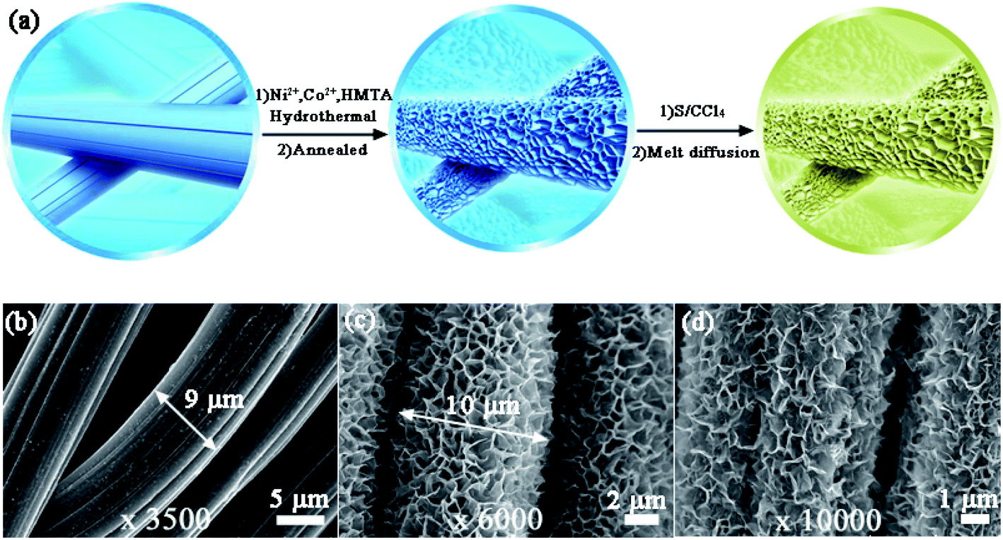 | ||
Fig. 1 Growth of interconnected NiCo2O4 nanosheet arrays on CC fibers and morphological characterization. (a) Schematic illustration of the preparation of NiCo2O4/CC and S/NiCo2O4/CC. Bare CC was treated in an autoclave with Ni2+, Co2+ and HMTA in methanol at 180 °C before being annealed at 350 °C to obtain NiCo2O4/CC. The as-prepared NiCo2O4/CC was then immersed in S/CCl4 solution to load sulfur and treated at 155 °C for melt diffusion of the infiltrated sulfur. SEM images of (b) CC (magnification: 3500), (c) NiCo2O4/CC (magnification: 6000) and (d) S/NiCo2O4/CC (magnification: 10![[thin space (1/6-em)]](https://www.rsc.org/images/entities/char_2009.gif) 000). 000). | ||
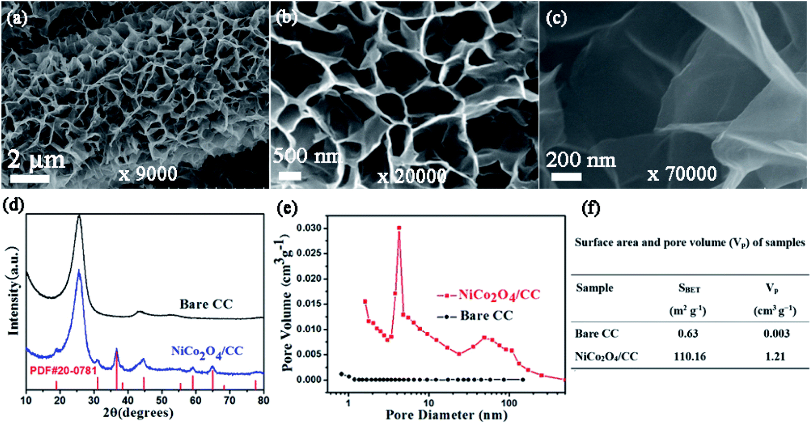 | ||
| Fig. 2 Characterization of NiCo2O4/CC. SEM images of the NiCo2O4 nanosheets with magnifications of (a) 9000, (b) 20000 and (c) 70000, respectively. (d) XRD patterns of NiCo2O4/CC and CC. (e) Pore size distribution of NiCo2O4/CC and CC. (f) Surface area and pore volume of NiCo2O4/CC and CC. | ||
A detailed examination of the interconnected NiCo2O4 nanosheet arrays is shown in Fig. 2. The surface of the carbon cloth fibers is completely covered by vertically aligned interconnected NiCo2O4 nanosheets, with no exposure of the original smooth surface of the carbon fibers (Fig. 2a). The NiCo2O4 nanosheets form a honeycomb-like structure. In a typical polygon constructed from the NiCo2O4 nanosheets, the average side length is 500–1000 nm (Fig. 2b). With even higher magnification, the NiCo2O4 nanosheets show a certain degree of transmittance, indicating the thinness of the nanosheets (Fig. 2c). The interconnected NiCo2O4 nanosheet arrays significantly improve the surface area, as will be stated below, and provide a platform for sulfur infiltration. The XRD peaks of NiCo2O4/CC are assigned to the cubic spinel NiCo2O4 phase (JCPDS card no. 20-0781) and the carbon cloth (Fig. 2d). The pore size distribution curve of NiCo2O4/CC indicates that the majority of the pores are at around 4 nm, and simultaneously there are micropores and macropores existing (Fig. 2e). Owing to the NiCo2O4 nanosheet coating on the carbon fibers, both the surface area and the pore volume are improved two orders of magnitude, from 0.63 to 110.16 m2 g−1 and from 0.003 to 1.21 cm3 g−1, respectively (Fig. 2f). The low surface area of CC is verified by the high smoothness of both the surface (Fig. 1b) and the interior region (Fig. 3b).
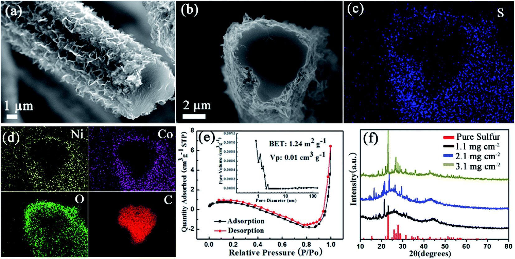 | ||
| Fig. 3 Characterization of S/NiCo2O4/CC. (a) SEM images of S/NiCo2O4/CC. (b) Cross-sectional view of S/NiCo2O4/CC. (c and d) EDX mapping of the cross section of S/NiCo2O4/CC with elements S, Ni, Co, O and C. (e) N2 adsorption–desorption isotherms and (inset) pore size distribution of S/NiCo2O4/CC. (f) XRD patterns of S/NiCo2O4/CC with different sulfur loadings and sulfur. | ||
Following the characterization of NiCo2O4/CC (Fig. 2), S/NiCo2O4/CC was carefully examined (Fig. 3). A bird view of the S/NiCo2O4/CC fiber reveals a coarse surface and a smooth cross section (Fig. 3a). The side view of the S/NiCo2O4/CC fiber shows a smooth heart-shaped cross section, with a core-shelled fiber structure of S/NiCo2O4/CC possessing the core of the CC fiber and the shell of S/NiCo2O4 (Fig. 3b). Elemental analyses of S, Ni, Co, O, and C (Fig. 3c and d) further verify the core–shell structure of S/NiCo2O4/CC. Sulfur does not exist inside the carbon fiber but is spread all over the coating layer of S/NiCo2O4 (Fig. 3c), indicating that the carbon fiber acts only as a current collector and the interconnected NiCo2O4 nanosheets as the host for sulfur. In other words, sulfur can stay only in the NiCo2O4 layer and will not able to penetrate into the interior of the carbon fiber. This observation agrees well with the BET results of bare CC and NiCo2O4/CC. While the specific surface area of CC is merely 0.6 m2 g−1, with the growth of the nanosheets the surface area of NiCo2O4/CC increases to 110 m2 g−1; further, with the loading of sulfur, the surface area drops back to 1.2 m2 g−1 (Fig. 3e and S4†). As for the other elements Ni, Co, O and C, their dispersion patterns are easy to understand. Ni and Co coexist outside of the carbon fiber; the intensity of O is higher for the exterior than for the interior of the carbon fiber; carbon is only present in the area of the carbon cloth fiber. S/NiCo2O4/CC samples with different sulfur loadings (from 1.1 to 3.1 mg cm−2) are characterized with XRD, verifying the presence of sulfur with the same orthorhombic structure as pure sulfur powder (Fig. 3f). With the increase of the sulfur content, the intensity of the characteristic peaks for sulfur increases accordingly.
The properties of S/NiCo2O4/CC are further explored with TGA and XPS. After heating to 300 °C, the weight of S/CC stabilizes up to 600 °C. The interaction between sulfur and carbon is weak, and therefore sulfur is completely lost below 300 °C, in accordance with the thermodynamic behavior of pure sulfur.43,44 In contrast, the weight of S/NiCo2O4/CC continues to decrease above 300 °C, which might be ascribed to the strong bonding between elemental sulfur and NiCo2O4, as will be shown below with XPS results. The Ni 2p3/2 XPS spectrum of the initial S/NiCo2O4/CC exhibits a spin–orbit doublet at 856.0 and 854.4 eV, corresponding to Ni3+ and Ni2+, respectively. Above 300 °C, the peaks for Ni3+ and Ni2+ shift to 856.5 and 854.7 eV, respectively. Similarly, the two peaks in the Co 2p3/2 spectrum shift from 781.3 to 781.8 and from 779.6 eV to 779.9 eV, respectively, after heating to 300 °C. The peak position variations of Ni 2p3/2 and Co 2p3/2 spectra might be attributed to the electron transfer between sulfur and Ni/Co atoms, manifesting the strong chemical interaction between NiCo2O4 and S8.33,45,46 This speculation is confirmed from the S 2p XPS spectrum (Fig. 4d). For S/NiCo2O4/CC above 300 °C, there are two multiple S 2p spectra, which are separated into three sulfur environments. The peaks at 165.0 and 163.9 eV are ascribed to the bridging sulfur (SB) of S8. The peaks at 169.7 and 168.6 eV correspond to the polythionate complex, which was produced from the oxidation of sulfur by NiCo2O4. Moreover, the peaks for Co2+/Co3+ and Ni2+/Ni3+ shift to a higher binding energy by 0.3–0.5 eV above 300 °C, which is ascribed to the strong chemical affinity between sulfur and Ni/Co cations, evidenced by the S 2p peaks at 163.8 and 162.6 eV for S–Ni and S–Co bonding. In contrast, for S/NiCo2O4/CC before heating, the interactions of S–Ni and S–Co are evidently weaker (Fig. S5†).
 | ||
| Fig. 4 TGA and XPS characterization of S/NiCo2O4/CC. (a) TGA curves of S/CC and S/NiCo2O4/CC. High-resolution XPS spectra of (b) Ni 2p3/2 and (c) Co 2p3/2 for S/NiCo2O4/CC before and after heating to 300 °C and (d) S 2p of S/NiCo2O4/CC after heating to 300 °C. | ||
As stated above, the S/NiCo2O4/CC cathode shows several advantages compared to S/CC. First, because of the two-orders-of-magnitude higher specific surface area of NiCo2O4/CC than CC, sulfur dispersion in S/NiCo2O4/CC presents significantly higher homogeneity, which might improve the specific capacity, rate performance and cycle life. Second, S–Ni and S–Co interactions render strong bonding between sulfur species and NiCo2O4/CC, and hence tend to suppress polysulfide dissolution and diffusion. Third, the interconnected NiCo2O4 nanosheet arrays with large spaces among the sheets allow better electrolyte permeation and solve the volume expansion problem caused by S/Li2S transition.
In light of the merits mentioned above, S/NiCo2O4/CC shows significantly improved performance compared to S/CC (Fig. 5). The S/NiCo2O4/CC cathode delivers an initial discharge capacity of 1480 mA h g−1 (∼88.4% of the theoretical specific capacity), much higher than the 1048 mA h g−1 for S/CC, demonstrating the functionality and effectiveness of the NiCo2O4 nanosheets grown on carbon fibers. This high capacity of 1480 mA h g−1 for the S/NiCo2O4/CC cathode is among the best results compared to the reports in the literature.47–49 Both the S/NiCo2O4/CC and S/CC electrodes show typical discharge and charge curves of a Li–S battery with a lithium anode and an elemental sulfur cathode. There are two discharge plateaus at 2.35 and 2.05 V (vs. Li+/Li), which, in consequence, are attributed to the reduction of sulfur (S8) to soluble long-chain LiPS (Li2Sx, 4 ≤ x ≤ 8) and then the insoluble short-chain LiPS (Li2S2/Li2S). The electrochemical reactions during the charge process mainly occur between 2.2 and 2.4 V. When increasing the sulfur loading, the capacity drops. At a loading of 3.08 mg cm−2, the capacity remains at around 689 mA h g−1, still an acceptable performance for Li–S batteries (Fig. S6†). At a higher rate of 0.5C, the S/NiCo2O4/CC cathode delivers an initial discharge capacity of 1090 mA h g−1 and a high reversible capacity of 826 mA h g−1 after 400 cycles, corresponding to a high capacity retention of 76% and a low capacity decay rate of mere 0.060% per cycle (Fig. 5b). In contrast, the specific capacities for S/CC are evidently lower than those for S/NiCo2O4/CC. For the first five cycles, as clearly shown in Fig. 5c, the capacities for S/CC are much lower. Besides, the initial coulombic efficiency for S/CC is extremely low (<80%), in contrast to the greatly higher coulombic efficiency (>99%) for S/NiCo2O4/CC (Fig. 5c and S7†). During the 400 cycles at 0.5C, the charge/discharge voltage plateaus remain almost the same (Fig. 5d) and the morphology can be well maintained (Fig. S8†), indicating the high stability of the S/NiCo2O4/CC cathode. Besides, when further improving the sulfur loading, the S/NiCo2O4/CC cathode also showed good cycling stability (Fig. S9†).
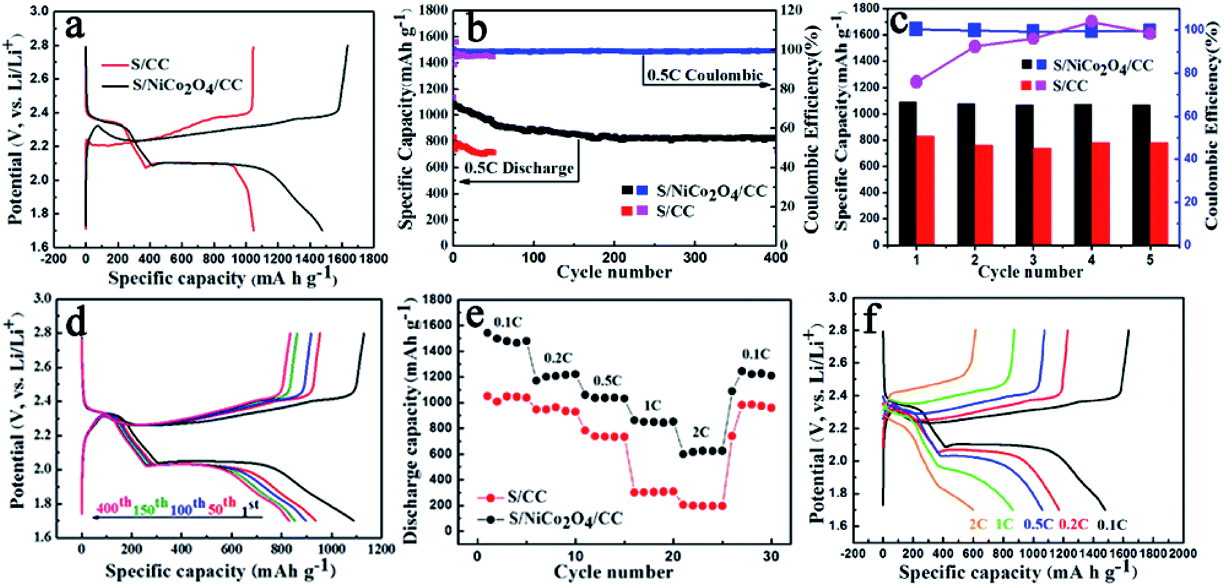 | ||
| Fig. 5 Electrochemical performance of S/CC and S/NiCo2O4/CC (sulfur loading: 1.1–1.3 mg cm−2). (a) Comparison of the first charge–discharge profiles at 0.1C for S/CC and S/NiCo2O4/CC. (b) Cycling performances and coulombic efficiencies of S/CC and S/NiCo2O4/CC at 0.5C. (c) Specific capacities and coulombic efficiencies of S/CC and S/NiCo2O4/CC for the first five cycles at 0.5C. (d) Charge–discharge profiles during cycling at 0.5C for S/NiCo2O4/CC at the 1st, 50th, 100th, 150th and 400 cycles. (e) Capacities at various rates from 0.1 to 2C. (f) Charge–discharge profiles for S/NiCo2O4/CC at various rates from 0.1 to 2C. | ||
Further, the superior battery performance including higher specific capacity, enhanced cycling stability and improved rate performance for the S/NiCo2O4/CC cathode compared to the S/CC cathode is demonstrated in Fig. 5e. When cycled at 0.1, 0.2, 0.5, 1 and 2C, the discharge capacities of the S/NiCo2O4/CC cathode are 1480, to 1200, 1059, 850 and 624 mA h g−1, respectively. In contrast, for the S/CC cathode, the capacities at 1 and 2C are significantly lower, at levels of 300 and 200 mA h g−1, respectively. When the current density returns to 0.1C, a high capacity of 1250 mA h g−1 is achieved, demonstrating the excellent structural stability of the S/NiCo2O4/CC cathode at the higher rates of 1C and 2C. The discharge/charge voltage plateaus for the S/NiCo2O4/CC cathode at varied rates from 0.1C to 2C are presented (Fig. 5f). The higher the rate, the lower the capacity and the larger the polarization is. When increasing the rate from 0.1C to 1C, the discharge voltage plateau, particularly the second one, becomes lower and shortens. At 2C, the second discharge voltage plateau almost disappears and the capacity keeps decreasing. Similarly, from 0.1 to 2C, the charge voltage plateau increases from around 2.3 to 2.5 V, and shortens. Moreover, the EIS measurements for S/CC and S/NiCo2O4/CC after cycling at 100% charge state were carried out and are shown in Fig. S10.† The EIS spectra of S/CC show two depressed semicircles while the EIS spectra of S/NiCo2O4/CC are composed of only one depressed semicircle in high frequency regions. As indicated in ref. 50, the semicircle in the middle frequency range is caused by the solid Li2S (or Li2S2) film on the matrix in the cathode; the impedance spectra of the fully charged cathode should display only one semicircle. This indicates that, after recharging, the solid Li2S does not entirely transform back into the polysulfides for S/CC. However, the semicircle due to the solid Li2S was not detected for S/NiCo2O4/CC, indicating that the solid Li2S entirely transformed back into polysulfides. Therefore, the EIS results further confirm that NiCo2O4 could act as a catalyst to improve the electrochemical kinetics for polysulfide conversion.
For the Li–S battery cathode, soluble LiPS are formed during the transition between S and Li2S/Li2S2 for both the charge and discharge processes. Hosts that can adsorb LiPS and catalyze/accelerate their electrochemical transformations are therefore needed, because they are capable of improving the performance by retaining LiPS against diffusion towards the anode and enhancing the charge transfer kinetics. In light of these considerations, Fig. 6 depicts the polysulfide adsorption properties of NiCo2O4/CC; Fig. 7 shows the boosted kinetics of the S/NiCo2O4/CC cathode, and Fig. 8 illustrates the mechanism of the improved battery performance.
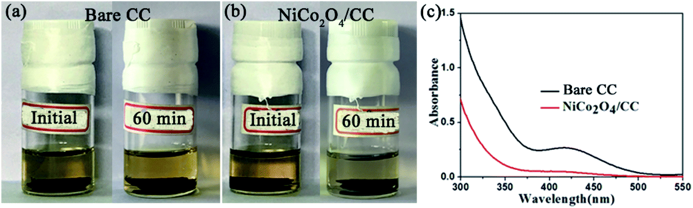 | ||
| Fig. 6 Polysulfide adsorption properties of CC and NiCo2O4/CC. Visual experiments with (a) CC and (b) NiCo2O4/CC placed in the solution of Li2S4/DOL/DME (2 mmol, DOL:DME volume ratio 1:1) at the beginning and after 60 min. (c) UV-vis absorption curves of Li2S4/DOL/DME solution after 1 h adsorption by bare CC and NiCo2O4/CC. | ||
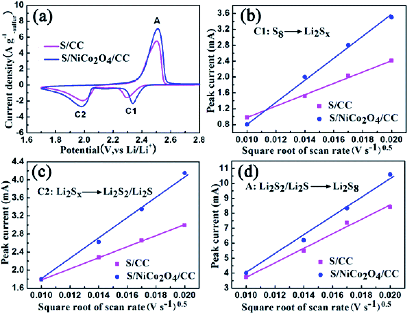 | ||
| Fig. 7 (a) CV curves for S/CC and S/NiCo2O4/CC at 0.4 mV s−1. (b–d) Plots of the peak current against the square root of scan rate for peaks C1, C2 and A. | ||
 | ||
| Fig. 8 Schematic illustration of the charge/discharge properties of the Li–S cells with S/NiCo2O4/CC and S/CC cathodes. | ||
Polysulfide adsorption of NiCo2O4/CC was revealed with a visual experiment and UV-vis absorption test. CC and NiCo2O4/CC was separately placed in the yellow solution of Li2S4. After 60 min, the Li2S4 solution with NiCo2O4/CC faded to colorless while the other with CC stayed unchanged (Fig. 6a and b), demonstrating the superior adsorption properties of the polar NiCo2O4 nanosheets. The nonpolar CC has no such adsorption ability. Besides the polarity of NiCo2O4, the high surface area is another determining factor for the excellent adsorption of LiPS. The pores ranging from micropores to macropores offer abundant adsorption sites to entrap the soluble LiPS on NiCo2O4 nanosheets. The supernatant was then analyzed with UV-vis absorption (Fig. 6c). The characteristic absorption peak of S42− at 410 nm remains for CC, but disappears for NiCo2O4/CC. The strong polysulfide adsorption of NiCo2O4/CC enables the higher capacity and enhanced cycle stability of S/NiCo2O4/CC compared to S/CC.
In a typical CV comparison, the cathodic peaks located at 2.32 (peak C1) and 2.10 V (peak C2) correspond to the gradual reduction of sulfur to LiPS and then to Li2S2/Li2S (Fig. 7a). The sharp peak located at 2.50 V (peak A) in the anodic scan represents the reverse conversion. The peak currents for S/NiCo2O4/CC are larger than those for S/CC. Besides, the cathodic peak C1 for S/NiCo2O4/CC is at a higher potential than that for S/CC. These characteristics indicate the improved electrochemical kinetics for S/NiCo2O4/CC.
To further study the electrochemical kinetics, CV measurements were carried out with scan rates of 0.1, 0.2, 0.3 and 0.4 mV s−1 (Fig. S11†). The maximum currents for the three peaks of C1, C2 and A are plotted against the square root of scan rates separately (Fig. 7b–d). They all possess a linear relationship, with the slope representing the diffusion rate of lithium ions, according to the Randles–Sevcik equation (ESI†).51,52 Meanwhile, for each redox peak, the slope for S/NiCo2O4/CC is larger than that for S/CC, indicating the accelerated diffusion of LiPS owing to the interconnected NiCo2O4 nanosheet arrays on the CC fibers. The adsorption and catalytic properties of NiCo2O4 nanosheets enhance the transformation rates of sulfur species, thereby boosting the diffusion of LiPS. NiCo2O4 as a catalyst accelerates the charge-transfer process and improves the electrochemical kinetics.
For the S/NiCo2O4/CC cathode, the interconnected NiCo2O4 nanosheet arrays act as a polar host, absorber and catalyst for the sulfur species, and the CC fibers enhance the electrical conductivity. As a host, the distinctive structure and the high surface area of NiCo2O4 cause homogeneous dispersion of elemental sulfur, as well as the discharge products and intermediates. The polar feature of NiCo2O4 attracts soluble LiPS, thus retaining them and preventing their diffusion towards the anode side. In contrast, the nonpolar CC fiber has no such effect (Fig. 8). The combined effects of the interconnected NiCo2O4 nanosheet arrays therefore endow the S/NiCo2O4/CC cathode with greatly improved electrochemical performances compared to S/CC. As shown by demonstration, a Li–S coin cell with the S/NiCo2O4/CC cathode is capable of illuminating LED lights for 6 h (Fig. S12†).
3. Conclusion
In summary, interconnected NiCo2O4 nanosheet arrays on carbon cloth fibers are proposed as a polar host, adsorber and catalyst for sulfur species. As a host, the distinctive structure and the high surface area of NiCo2O4 cause homogeneous dispersion of elemental sulfur, as well as the discharge products and intermediates. The polar feature of NiCo2O4 attracts soluble LiPS, thus retaining them and preventing their diffusion towards the anode side. In contrast, the nonpolar carbon fiber has no such effect. NiCo2O4 as a catalyst accelerates the charge-transfer process and improves the electrochemical kinetics. Consequently, the prepared S/NiCo2O4/CC electrodes show a high initial capacity of 1480 mA h g−1 at 0.1C and enhanced rate capability (850 and 624 mA h g−1 at 1C and 2C, respectively), as well as stable cyclability (822.3 mA h g−1 after 400 cycles at 0.5C with a low capacity decay rate of 0.060% per cycle).4. Experimental section
Synthesis of NiCo2O4/CC
Co(NO3)2·6H2O (0.5 mmol), Ni(NO3)2·6H2O (1 mmol), and Hexamethylenetetramine (3 mmol) were added into an autoclave with methanol (24 mL) to form a homogeneous light pink solution under stirring. Then as-cleaned carbon cloth was vertically placed into the autoclave, which was heated at 180 °C for 12 h. The as-treated carbon cloth was washed and annealed at 350 °C for 3 h to obtain NiCo2O4/CC.Synthesis of S/NiCo2O4/CC
S/NiCo2O4/CC was prepared by sulfur impregnation into NiCo2O4/CC followed by melt diffusion. The sublimed sulfur was first dissolved in carbon tetrachloride (CCl4) and then the as-obtained NiCo2O4/CC was immersed into the sulfur-containing solution. After immersing for a certain period of time, the piece was taken out for drying. The sulfur loading amount of S/NiCo2O4/CC was controlled by specifying the immersion time and the concentration of the S/CCl4 solution. In order to achieve better dispersion of sulfur in S/NiCo2O4/CC, the melt diffusion process (155 °C for 12 h) was further applied. Following a similar procedure, the control sample S/CC was prepared.Polysulfide adsorption experiment
Li2S and S at a molar ratio of 1:3 were added into DOL/DME (volume ratio 1:1) under stirring at 60 °C for 12 h to form a homogeneous Li2S4 solution (2 mmol L−1). NiCo2O4/CC and bare CC were added into the Li2S4 solution (3 mL) and allowed to rest for 1 h, respectively. Then the supernatants were analyzed with a UV-Vis Spectrophotometer (UV-Vis, Shimadzu, UV2450).
Electrochemical measurements
The S/CC and S/NiCo2O4/CC pieces were cut into a circular shape with a diameter of 14 mm to use as the cathodes of Li–S batteries. The integrated cathode, the lithium metal anode and a Celgard 2300 separator were assembled into CR2032 coin cells in an argon-filled glove box with both moisture and oxygen contents below 0.1 ppm. The electrolyte was composed of LiTFSI (1 M) and LiNO3 (0.2 M) in DME:DOL (1:1, v/v). Galvanostatic discharge–charge tests of S/CC and S/NiCo2O4/CC were carried out on a Battery Measurement System (Shenzhen Neware Electronic Co., China) with a voltage window of 1.7–2.8 V versus Li+/Li. The current density (1.0C = 1675 mA g−1) and the specific capacity were calculated based on the mass of the loaded sulfur. If not specified, the sulfur loading was controlled at 1.1–1.3 mg cm−2. CV curves were obtained at different scan rates from 0.1 to 0.4 mV s−1 between 1.7 and 2.8 V (vs. Li/Li+). Electrochemical impedance spectroscopy (EIS) tests were carried out at 5 mV amplitude with the frequency from 100 kHz to 10 mHz.
Materials characterization
X-ray diffraction (XRD) tests were performed between 10° and 80° at 40 kV and 50 mA on a Bruker D8 ADVANCE X-ray Diffractometer. The microscopic morphology and structure were determined on an SU8820 Hitachi field-emission scanning electron microscope (FESEM). TG analysis was conducted on a DSC3+ Mettler Toledo. The sample was heated in a nitrogen atmosphere at 10 °C min−1 from room temperature to 600 °C. BET analysis was carried out on ASAP2020 Micromeritics Instruments.Conflicts of interest
The authors declare no conflict of interest.Acknowledgements
This work received financial support from the National Natural Science Foundation of China (21606051, 21576054, 21905099 and 51703037) and the Foundation of Basic and Applied Basic Research of Guangdong Province (2019B1515120087). We would like to thank Dr Shengbo Han, Dr Gao Cheng, Dr Qi Liu and Dr Peng Liu from the Faculty of Chemical Engineering and Light Industry, Guangdong University of Technology for their help in materials characterization.References
- J. B. Goodenough and K. S. Park, J. Am. Chem. Soc., 2013, 135, 1167–1176 CrossRef CAS.
- N. Nitta, F. Wu, J. T. Lee and G. Yushin, Mater. Today, 2015, 18, 252–264 CrossRef CAS.
- M. Winter, B. Barnett and K. Xu, Chem. Rev., 2018, 118, 11433–11456 CrossRef CAS.
- J. B. Goodenough and Y. Kim, Chem. Mater., 2010, 22, 587–603 CrossRef CAS.
- V. Etacheri, R. Marom, R. Elazari, G. Salitra and D. Aurbach, Energy Environ. Sci., 2011, 4, 3243–3262 RSC.
- L. C. Zeng, W. H. Li, Y. Jiang and Y. Yu, Rare Met., 2017, 36, 339–364 CrossRef CAS.
- X. H. Zhao, G. Cheruvally, C. Kim, K. K. Cho, H. J. Ahn, K. W. Kim and J. H. Ahn, J. Electrochem. Sci. Technol., 2016, 7, 97–114 CrossRef CAS.
- C. Xu, Y. Yang, H. Wang, B. Xu, Y. Li, R. Tan, X. Duan, D. Wu, M. Zhuo and J. Ma, Chem.–Asian J., 2020, 15, 3584–3598 CrossRef CAS.
- H. Wang, J. He, J. Liu, S. Qi, M. Wu, J. Wen, Y. Chen, Y. Feng and J. Ma, Adv. Funct. Mater., 2021, 31, 2002578 CrossRef CAS.
- S. Qi, H. Wang, J. He, J. Liu, C. Cui, M. Wu, F. Li, Y. Feng and J. Ma, Sci. Bull., 2020 DOI:10.1016/j.scib.2020.09.018.
- Y. Chen, Z. Wang, X. Li, X. Yao, C. Wang, Y. Li, W. Xue, D. Yu, S. Y. Kim, F. Yang, A. Kushima, G. Zhang, H. Huang, N. Wu, Y.-W. Mai, J. B. Goodenough and J. Li, Nature, 2020, 578, 251–255 CrossRef CAS.
- Y. Wang, Y. Wang, Y.-X. Wang, X. Feng, W. Chen, X. Ai, H. Yang and Y. Cao, Chem, 2019, 5, 2547–2570 CAS.
- X. Xu, K. Lin, D. Zhou, Q. Liu, X. Qin, S. Wang, S. He, F. Kang, B. Li and G. Wang, Chem, 2020, 6, 902–918 CAS.
- S. Kaskel, Energy Technol., 2019, 7, 1900940 CrossRef.
- K. L. Zhu, C. Wang, Z. X. Chi, F. Ke, Y. Yang, A. B. Wang, W. K. Wang and L. X. Miao, Front. Energy Res., 2019, 7, 123 CrossRef.
- S. Dorfler, H. Althues, P. Hartel, T. Abendroth, B. Schumm and S. Kaskel, Joule, 2020, 4, 539–554 CrossRef.
- H. Ye, M. Li, T. Liu, Y. Li and J. Lu, ACS Energy Lett., 2020, 5, 2234–2245 CrossRef CAS.
- X. Zhang, K. Chen, Z. Sun, G. Hu, R. Xiao, H.-M. Cheng and F. Li, Energy Environ. Sci., 2020, 13, 1076–1095 RSC.
- W. Xu, H. Pang, H. Zhou, Z. Jian, R. Hu, Y. Xing and S. Zhang, RSC Adv., 2020, 10, 2670–2676 RSC.
- E. Cha, M. Patel, S. Bhoyate, V. Prasad and W. Choi, Nanoscale Horiz., 2020, 5, 808–831 RSC.
- M. Wang, H. Zhang, Q. Wang, C. Qu, X. Li and H. Zhang, ACS Appl. Mater. Interfaces, 2015, 7, 3590–3599 CrossRef CAS.
- H. Zhang, Q. Gao, W. Qian, H. Xiao, Z. Li, L. Ma and X. Tian, ACS Appl. Mater. Interfaces, 2018, 10, 18726–18733 CrossRef CAS.
- Q. Wang, N. Yan, M. Wang, C. Qu, X. Yang, H. Zhang, X. Li and H. Zhang, ACS Appl. Mater. Interfaces, 2015, 7, 25002–25006 CrossRef CAS.
- L. Chen, H. Yu, W. Li, M. Dirican, Y. Liu and X. Zhang, J. Mater. Chem. A, 2020, 8, 10709–10735 RSC.
- S. Wang, H. Chen, J. Liao, Q. Sun, F. Zhao, J. Luo, X. Lin, X. Niu, M. Wu, R. Li and X. Sun, ACS Energy Lett., 2019, 4, 755–762 CrossRef CAS.
- X. Yu, G. Zhou and Y. Cui, ACS Appl. Mater. Interfaces, 2019, 11, 3080–3086 CrossRef CAS.
- Z. Li, J. Zhang and X. W. Lou, Angew. Chem., Int. Ed. Engl., 2015, 54, 12886–12890 CrossRef CAS.
- J. Pu, Z. Shen, J. Zheng, W. Wu, C. Zhu, Q. Zhou, H. Zhang and F. Pan, Nano Energy, 2017, 37, 7–14 CrossRef CAS.
- W.-G. Lim, C. Jo, A. Cho, J. Hwang, S. Kim, J. W. Han and J. Lee, Adv. Mater., 2019, 31, 1806547 CrossRef.
- Y. Z. Song, S. Y. Zhao, Y. R. Chen, J. S. Cai, J. Li, Q. H. Yang, J. Y. Sun and Z. F. Liu, ACS Appl. Mater. Interfaces, 2019, 11, 5687–5694 CrossRef CAS.
- X. Liu, Q. He, H. Yuan, C. Yan, Y. Zhao, X. Xu, J. Q. Huang, Y. L. Chueh, Q. Zhang and L. Q. Mai, J. Energy Chem., 2020, 48, 109–115 CrossRef.
- D. J. Xiao, H. F. Zhang, C. M. Chen, Y. D. Liu, S. X. Yuan and C. X. Lu, Chemelectrochem, 2017, 4, 2959–2965 CrossRef CAS.
- L. Y. Hu, C. L. Dai, H. Liu, Y. Li, B. L. Shen, Y. M. Chen, S. J. Bao and M. W. Xu, Adv. Energy Mater., 2018, 8, 1800709 CrossRef.
- Y. T. Liu, D. D. Han, L. Wang, G. R. Li, S. Liu and X. P. Gao, Adv. Energy Mater., 2019, 9, 1803477 CrossRef.
- Z. Cui, S.-A. He, Q. Liu and R. Zou, Dalton Trans., 2020, 49, 6876–6883 RSC.
- J. Ma, J. Li, R. Guo, H. Xu, F. Shi, L. Dang, Z. Liu, J. Sun and Z. Lei, J. Power Sources, 2019, 428, 124–130 CrossRef CAS.
- T.-S. Wang, X. Liu, Y. Wang and L.-Z. Fan, Adv. Funct. Mater., 2020, 2001973, DOI:10.1002/adfm.202001973.
- K. Kordek, L. Jiang, K. Fan, Z. Zhu, L. Xu, M. Al-Mamun, Y. Dou, S. Chen, P. Liu, H. Yin, P. Rutkowski and H. Zhao, Adv. Energy Mater., 2019, 9, 1802936 CrossRef.
- R. B. Rakhi, W. Chen, D. Cha and H. N. Alshareef, Nano Lett., 2012, 12, 2559–2567 CrossRef CAS.
- F. Deng, L. Yu, G. Cheng, T. Lin, M. Sun, F. Ye and Y. Li, J. Power Sources, 2014, 251, 202–207 CrossRef CAS.
- J. R. Hao, Y. D. Pan, W. H. Chen, X. B. Zhu, Y. H. Zhou and S. L. Chou, J. Mater. Chem. A, 2019, 7, 27247–27255 RSC.
- Y. D. Pan, Y. H. Zhou, Q. Zhao, Y. H. Dou, S. L. Chou, F. Y. Cheng, J. Chen, H. K. Liu, L. Jiang and S. X. Dou, Nano Energy, 2017, 33, 205–212 CrossRef CAS.
- Y. Cheng, S. Ji, Y. Liu and J. Liu, Arabian J. Chem., 2019, 12, 3517–3525 CrossRef CAS.
- Y.-X. Wang, L. Huang, L.-C. Sun, S.-Y. Xie, G.-L. Xu, S.-R. Chen, Y.-F. Xu, J.-T. Li, S.-L. Chou, S.-X. Dou and S.-G. Sun, J. Mater. Chem., 2012, 22, 4744–4750 RSC.
- J. Pu, Z. H. Shen, J. X. Zheng, W. L. Wu, C. Zhu, Q. W. Zhou, H. G. Zhang and F. Pan, Nano Energy, 2017, 37, 7–14 CrossRef CAS.
- C. Li, S. Dong, D. Guo, Z. Zhang, M. Wang and L. Yin, Electrochim. Acta, 2017, 251, 43–50 CrossRef CAS.
- F. Pei, L. L. Lin, D. H. Ou, Z. M. Zheng, S. G. Mo, X. L. Fang and N. F. Zheng, Nat. Commun., 2017, 8, 482 CrossRef.
- Y. Kim, H. Han, Y. Noh, J. Bae, M. H. Ham and W. B. Kim, ChemSusChem, 2019, 12, 824 CrossRef CAS.
- M. Chen, S. Jiang, C. Huang, X. Wang, S. Cai, K. Xiang, Y. Zhang and J. Xue, ChemSusChem, 2017, 10, 1803–1812 CrossRef CAS.
- L. Yuan, X. Qiu, L. Chen and W. Zhu, J. Power Sources, 2009, 189, 127–132 CrossRef CAS.
- A. Windmüller, C. A. Bridges, C.-L. Tsai, S. Lobe, C. Dellen, G. M. Veith, M. Finsterbusch, S. Uhlenbruck and O. Guillon, ACS Appl. Energy Mater., 2018, 1, 715–724 CrossRef.
- T. Kim, W. Choi, H.-C. Shin, J.-Y. Choi, J. M. Kim, M.-S. Park and W.-S. Yoon, J. Electrochem. Sci. Technol., 2020, 11, 14–25 CrossRef CAS.
Footnote |
| † Electronic supplementary information (ESI) available. See DOI: 10.1039/d0na00947d |
| This journal is © The Royal Society of Chemistry 2021 |