 Open Access Article
Creative Commons Attribution 3.0 Unported Licence
Fe7Se8 encapsulated in N-doped carbon nanofibers as a stable anode material for sodium ion batteries†
Le
Hu‡
a,
Chaoqun
Shang‡
 *a,
Xin
Wang
 *abc and
Guofu
Zhou
abc
aGuangdong Provincial Key Laboratory of Optical Information Materials and Technology & Institute of Electronic Paper Displays, South China Academy of Advanced Optoelectronics, South China Normal University, Guangzhou 510006, China. E-mail: chaoqun.shang@ecs-scnu.org; wangxin@scnu.edu.cn
bNational Center for International Research on Green Optoelectronics, South China Academy of Advanced Optoelectronics, South China Normal University, Guangzhou 510006, China
cInternational Academy of Optoelectronics at Zhaoqing, South China Normal University, Zhaoqing 526000, China
First published on 10th November 2020
Abstract
Transition metal chalcogenides especially Fe-based selenides for sodium storage have the advantages of high electric conductivity, low cost, abundant active sites, and high theoretical capacity. Herein, we proposed a facile synthesis of Fe7Se8 embedded in carbon nanofibers (denoted as Fe7Se8-NCFs). The Fe7Se8-NCFs with a 1D electron transfer network can facilitate Na+ transportation to ensure fast reaction kinetics. Moreover, Fe7Se8 encapsulated in carbon nanofibers, Fe7Se8-NCFs, can effectively adapt the volume variation to keep structural integrity during a continuous Na+ insertion and extraction process. As a result, Fe7Se8-NCFs present improved rate performance and remarkable cycling stability for sodium storage. The Fe7Se8-NCFs exhibit practical feasibility with a reasonable specific capacity of 109 mA h g−1 after 200 cycles and a favorable rate capability of 136 mA h g−1 at a high rate of 2 A g−1 when coupled with Na3V2(PO4)3 to assemble full sodium ion batteries.
Introduction
The economical concern of sodium ion batteries (SIBs) has made them one of the large scale energy storage systems to replace lithium ion batteries (LIBs).1,2 Besides, SIBs have similar electrochemical storage properties to LIBs, which provides sufficient references for the exploration of electrode materials for SIBs.3,4 Graphite as an anode employed in commercial LIBs exhibits undesirable sodium storage capability in SIBs with traditional carbonate-based electrolytes.5,6 Therefore, the research of SIB anode materials is still a great challenge compared to the great progress of cathode materials with promising electrochemical performance.7,8Over the past few years, tremendous efforts have been made to search for appropriate anode materials of SIBs, such as hard or soft carbon, alloy-type Sn/Sb/Bi, transition metal oxides/sulfides/phosphides/selenides, organic molecules, etc.9,10 As potential candidates, transition metal selenides especially Fe-based selenides have the advantages of high electric conductivity, low cost, abundant active sites, and high theoretical capacity.11,12 However, the large radius of sodium ions results in sluggish reaction kinetics and large volume variation during sodium ion insertion/deinsertion and further hinders the rate capability and cycling stability of the corresponding SIBs.13,14 To address these issues, downsizing the active materials to the nanoscale and surface coating to suppress the volume effect are common strategies.15,16 For example, Chen et al. reported that micro-nano hierarchitectures of urchin-like Fe3Se4 effectively display remarkable rate performance (200.2 mA h g−1 at 30 A g−1).17 Li and coworkers studied FeSe nanoparticles embedded in N-doped carbon (FeSe/N–C) with stable cycling performance (333.9 mA h g−1 after 800 cycles).18 Nevertheless, further improvement of the sodium storage capability of Fe-based selenides is still a challenge.
In this paper, we proposed a facile synthesis of Fe7Se8 embedded in carbon nanofibers (denoted as Fe7Se8-NCFs), which was further assembled as an anode material for SIBs. Taking advantage of downsized dimensions, effective carbon buffer protection, and the 1D nanofiber electron transfer network, Fe7Se8-NCFs shows remarkable stability (232 mA h g−1 at 0.1 A g−1, 400 cycles) and improved rate capability (153 mA h g−1, 2 A g−1) in half-cells. The electrochemical kinetic analysis unveils that the surface pseudocapacitive process contributes largely to the capacity, which undoubtedly enhances the rate capability. Moreover, Fe7Se8-NCFs coupled with Na3V2(PO4)3 (denoted as NVP) also shows potential in full SIBs, which display favorable rate capability and reasonable reversible capacity.
Experimental section
Preparation of Fe7Se8-NCFs nanofibers
Polyacrylonitrile (PAN, 0.7 g) and iron(III) acetylacetonate (Fe(AcAc)3, 0.3 g) were mixed in dimethylformamide (DMF, 10 ml) by constantly stirring for 10 h to obtain a uniformly dispersed solution. Then, the as-prepared solution was put into a syringe and electrospun at a flow rate of 0.1 mm min−1 at high voltage (14 kV). The obtained Fe(AcAc)3/PAN nanofibers (0.1 g) and Se powder (0.2 g) were annealed at a temperature of 500 °C for 4 h (H2/Ar). For the comparative sample, Fe7Se8 powder was prepared by the same annealing process using Fe(AcAc)3 and Se powder (weight ratio: 1![[thin space (1/6-em)]](https://www.rsc.org/images/entities/char_2009.gif) :
:![[thin space (1/6-em)]](https://www.rsc.org/images/entities/char_2009.gif) 2). The N-doped carbon nanofibers (NCFs) were annealed by the same process using PAN nanofibers. NVP was prepared following a previous report.19 NaH2PO4 (0.85 g), NH4VO3 (0.47 g) and citric acid (0.77 g) were dissolved in deionized water (60 ml) with continuous agitation. Graphene oxide (0.04 g) was mixed into the above solution and then freeze-dried for 24 h. The as-prepared powder was calcined at 800 °C for 8 h (Ar/H2) to obtain NVP.20 The material characterization section is in the ESI.†
2). The N-doped carbon nanofibers (NCFs) were annealed by the same process using PAN nanofibers. NVP was prepared following a previous report.19 NaH2PO4 (0.85 g), NH4VO3 (0.47 g) and citric acid (0.77 g) were dissolved in deionized water (60 ml) with continuous agitation. Graphene oxide (0.04 g) was mixed into the above solution and then freeze-dried for 24 h. The as-prepared powder was calcined at 800 °C for 8 h (Ar/H2) to obtain NVP.20 The material characterization section is in the ESI.†
Electrochemical measurement
A slurry was prepared by mixing 80 wt% active material, 10 wt% Super P, and 10 wt% binder (polyvinylidene fluoride, PVDF) and was cast onto Cu foil and dried in a vacuum at 60 °C for 12 h to prepare the working electrode. The working electrode was cut into discs with a diameter of 12 mm. The full cell consists of the Fe7Se8-NCF anode and NVP cathode. The NVP cathode was prepared by mixing NVP, Super P and polytetrafluoroethylene (PTFE) (weight ratio: 8![[thin space (1/6-em)]](https://www.rsc.org/images/entities/char_2009.gif) :
:![[thin space (1/6-em)]](https://www.rsc.org/images/entities/char_2009.gif) 1
1![[thin space (1/6-em)]](https://www.rsc.org/images/entities/char_2009.gif) :
:![[thin space (1/6-em)]](https://www.rsc.org/images/entities/char_2009.gif) 1). For the NVP‖Fe7Se8-NCFs full cell, the mass ratio of the cathode and anode was controlled at 5
1). For the NVP‖Fe7Se8-NCFs full cell, the mass ratio of the cathode and anode was controlled at 5![[thin space (1/6-em)]](https://www.rsc.org/images/entities/char_2009.gif) :
:![[thin space (1/6-em)]](https://www.rsc.org/images/entities/char_2009.gif) 1. The electrolyte was NaClO4 (1 M) dissolved in a mixture of ethylene carbonate and dimethyl carbonate (volume ratio: EC/DMC = 1/1) solution with fluoroethylene carbonate (FEC: 5 vol%). Electrochemical impedance spectroscopy (EIS) measurements were performed in the frequency range from 100 kHz to 100 mHz. Cyclic voltammetry (CV) was performed on a BioLogic (VMP3) electrochemical workstation in the voltage range of 0.1–3 V.
1. The electrolyte was NaClO4 (1 M) dissolved in a mixture of ethylene carbonate and dimethyl carbonate (volume ratio: EC/DMC = 1/1) solution with fluoroethylene carbonate (FEC: 5 vol%). Electrochemical impedance spectroscopy (EIS) measurements were performed in the frequency range from 100 kHz to 100 mHz. Cyclic voltammetry (CV) was performed on a BioLogic (VMP3) electrochemical workstation in the voltage range of 0.1–3 V.
Results and discussion
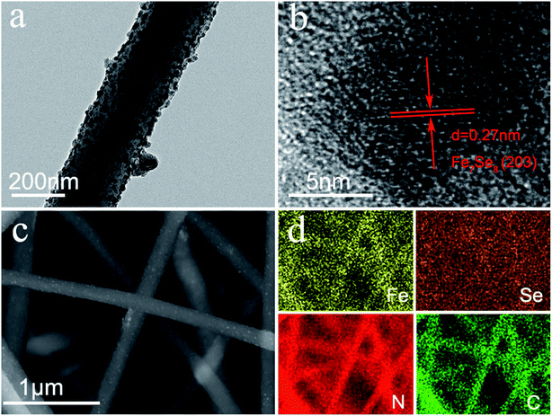
The synthesis process of the Fe7Se8-NCFs nanofibers is mainly divided into electrospinning and subsequent selenization processes (Fig. S1†). The SEM image of as-electrospun Fe(AcAc)3/PAN shows smooth and evenly distributed nanofibers, as exhibited in Fig. 1a and b. After the selenization process, Fe7Se8-NCFs well maintains the 1D fiber structure of Fe(AcAc)3/PAN and regular distribution (Fig. 1c and d). The cross-sectional SEM images of Fe7Se8-NCFs show abundant voids between the nanofibers, which facilitate the penetration of the electrolyte (Fig. S2†). Combined with SEM morphologies, the TEM image further reveals that the diameter of Fe7Se8-NCFs nanofibers is about 200 nm, and the Fe7Se8 nanoparticles are uniformly embedded in N-doped carbon nanofibers (Fig. 2a). The high-resolution TEM image (HRTEM, Fig. 2b) of Fe7Se8-NCFs shows a lattice fringe of 0.27 nm, indexed to the (203) plane of the Fe7Se8 phase. The SEM image and energy dispersive spectroscopy (EDS) elemental mappings reveal Fe, Se, N and C elements uniformly distributed in the carbon nanofibers (Fig. 2c and d). However, in Fig. S3,† the as-prepared Fe7Se8 bulk is composed of large aggregated particles due to lack of a fiber support.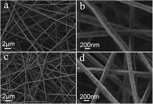 | ||
| Fig. 1 (a and b) SEM images of Fe(AcAc)3/PAN nanofibers; (c and d) SEM images of as-prepared Fe7Se8-NCFs. | ||
Fig. 3a displays the XRD pattern of Fe7Se8-NCFs and bulk Fe7Se8. The major diffraction peaks at 32.3, 42.0 and 50.2° are assigned to the (203), (206) and (220) planes of Fe7Se8 (PDF#33-0676). It should be noted that the XRD peaks of Fe7Se8-NCFs slightly shift to high 2θ. This indicates the existence of Se vacancies owing to the protection of the NCF substrate during selenization, which can enhance the electronic conductivity, guaranteeing fast electron transfer for Na+ insertion/extraction. The diffraction peaks of Fe7Se8-NCFs are broader than those of bulk Fe7Se8, which demonstrates the small crystal size of Fe7Se8 in the NCF matrix. This is beneficial to shorten the sodium ion diffusion length during sodium ion insertion and deinsertion. According to the Scherrer formula (the details are in the ESI†), the crystal size of Fe7Se8 in NCFs is ∼20 nm, while that of bulk Fe7Se8 is 40 nm. The Fe7Se8 content in the Fe7Se8-NCF composite was determined by a TGA test (Fig. S4a†). The mass loss below 200 °C is due to the evaporation of the residual moisture in the Fe7Se8-NCF sample. The temperature between 300 and 500 °C can be assigned to the oxidation of carbon fibers and Fe7Se8. When the temperature reaches 600 °C in air, the final combustion product of Fe7Se8-NCFs is Fe2O3 (Fig. S4b†).21 Thus, the content of Fe7Se8 in dried Fe7Se8-NCFs is ∼20.6%. An XPS test was performed to analyze the chemical composition of Fe7Se8-NCFs. The survey spectrum of Fe7Se8-NCFs illustrates the coexistence of Fe, Se, N and C elements in Fe7Se8-NCFs (Fig. S5a†). As presented in Fig. 3b, the Fe 2p spectrum can be divided into Fe2+ and Fe3+ for the spin–orbit doublet of Fe 2p1/2 and Fe 2p3/2. The peaks at 725.2 and 713.5 eV are assigned to 2p1/2 and 2p3/2 of Fe2+, and the peaks at 723.7 and 710.6 eV are ascribed to 2p1/2 and 2p3/2 of Fe3+, demonstrating the presence of Fe2+ and Fe3+ states in Fe7Se8-NCFs.22 In Fig. 3c, the XPS spectrum of Se 3d consists of Se 3d3/2 (59.5 and 58.6 eV) and 3d5/2 (56.3 and 55.7 eV).23 In Fig. 3d, the C 1s spectra displays three peaks located at 288.4 eV (C![[double bond, length as m-dash]](https://www.rsc.org/images/entities/char_e001.gif) O), 286.4 eV (C–N), and 284.8 eV (C–C/C
O), 286.4 eV (C–N), and 284.8 eV (C–C/C![[double bond, length as m-dash]](https://www.rsc.org/images/entities/char_e001.gif) C) respectively.24 The N-doping carbon layer not only enhances electronic conductivity to promote fast reaction kinetics, but also relieves volume variation to keep the stable structure of Fe7Se8-NCFs during repeated cycling. The XPS spectrum and detailed analysis of other elements (O and N) are exhibited in Fig. S5.† In the Raman analysis, the peaks at about 278, 330, and 405 cm−1 might be assigned to Fe–Se bonds in Fe7Se8-NCFs, and other peaks at 1358 cm−1 and 1589 cm−1 are ascribed to the D band and G band, respectively25 (Fig. S6†). The ID/IG of Fe7Se8-NCFs (1.76) and NCFs (1.64) indicates more defects of carbon on Fe7Se8-NCFs to promote reaction kinetics.
C) respectively.24 The N-doping carbon layer not only enhances electronic conductivity to promote fast reaction kinetics, but also relieves volume variation to keep the stable structure of Fe7Se8-NCFs during repeated cycling. The XPS spectrum and detailed analysis of other elements (O and N) are exhibited in Fig. S5.† In the Raman analysis, the peaks at about 278, 330, and 405 cm−1 might be assigned to Fe–Se bonds in Fe7Se8-NCFs, and other peaks at 1358 cm−1 and 1589 cm−1 are ascribed to the D band and G band, respectively25 (Fig. S6†). The ID/IG of Fe7Se8-NCFs (1.76) and NCFs (1.64) indicates more defects of carbon on Fe7Se8-NCFs to promote reaction kinetics.
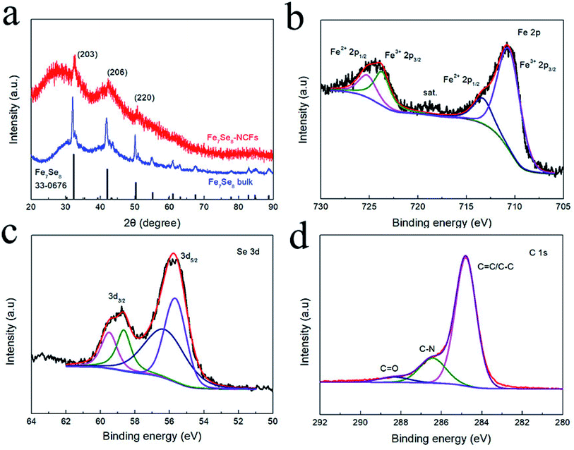 | ||
| Fig. 3 (a) XRD pattern of Fe7Se8-NCFs. High-resolution XPS spectra of Fe7Se8-NCFs: (b) Fe 2p; (c) Se 3d; (d) C 1s. | ||
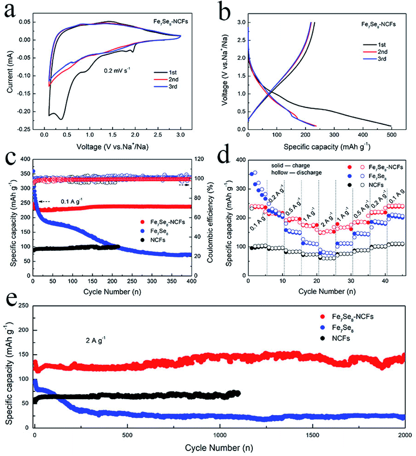
The electrochemical performance in sodium storage of Fe7Se8-NCFs was investigated by CV measurements (Fig. 4a). In the initial cycle, the sharp reduction peaks at 0.4 and 0.9 V originate from the generation of a solid electrolyte interface (SEI) film and irreversible Na+ insertion.26,27 In the following curves, the broad redox peaks at 1.6 and 0.9 V are well overlapped, indicating a reversible conversion reaction for Fe7Se8-NCFs. The redox peaks of the CV curves are not obvious, which might be due to the carbon effect in Fe7Se8-NCFs. The 1D carbon fiber as a buffer matrix maintains the structural integrity to guarantee a long cycle life. In Fig. 4b, the charge/discharge profiles of Fe7Se8-NCFs show that the initial charge/discharge specific capacity is 232/497 mA h g−1 and the corresponding initial coulombic efficiency (ICE) is 46.7%. The low ICE might be ascribed to solid electrolyte interface (SEI) formation and some irreversible side reactions, which are consistent with the CV result.28Fig. 4c depicts the cycling performance of Fe7Se8-NCFs compared with those of Fe7Se8 and NCFs. When the current density is 0.1 A g−1, Fe7Se8-NCFs delivers a reversible capacity of 223 mA h g−1 after 400 cycles with a capacity retention rate of 96.5%, providing an impressive CE of around 100%. The comparative Fe7Se8 displays a rapid decrease in current density from 359 to 73 mA h g−1 during the 400 cycles. The high initial specific capacity of comparative Fe7Se8 is due to the high theoretical specific capacity of the Fe7Se8 active material (419 mA h g−1). However, Fe7Se8 undergoes serious volume change during larger Na+ intercalation and deintercalation, which causes the active material to be pulverized with continuous capacity degradation. With the protection of NCFs, Fe7Se8-NCFs could adapt to volume expansion to retain a stable capacity. The rate capability of Fe7Se8-NCFs, Fe7Se8 and NCFs is further tested and compared, as exhibited in Fig. 4d. As the current density increases from 0.1 to 2 A g−1, Fe7Se8-NCFs delivers a specific capacity of 237, 215, 195, 175 and 153 mA h g−1. Impressively, when the current density is switched back to 0.1 A g−1, Fe7Se8-NCFs recovers a specific capacity of 238 mA h g−1 without any attenuation, demonstrating favorable rate performance of Fe7Se8-NCFs. In contrast, Fe7Se8 shows poor rate performance (from 357 to 70 mA h g−1 at 0.1 to 2 A g−1). The promising rate performance of Fe7Se8-NCFs could be attributed to the 1D carbon nanofibers, which can shorten the ion diffusion pathway to facilitate Na+ transportation. As shown in Table S1,† the research of Fe7Se8-NCFs for sodium storage exhibits stable electrochemical performance.29 Furthermore, Fig. 4e shows the long-term cycling stability of Fe7Se8-NCFs with a specific capacity of 148 mA h g−1 after 2000 cycles, which is more stable than those of Fe7Se8 and NCFs (the current density: 2 A g−1). These results further reveal the strong structural stability of Fe7Se8 encapsulated in 1D NCFs.
To deeply elucidate the stable carbon matrix structure of Fe7Se8-NCFs, the surface morphology of Fe7Se8-NCFs was observed before and after 100 cycles. The SEM morphology of fresh Fe7Se8-NCFs with regular nanofibers is shown in Fig. 5a. The cycled Fe7Se8-NCFs retains a flat and distinct 1D nanofiber structure with abundant voids (Fig. 5b), which is similar to the original shape. Meanwhile, the slight volume expansion of cycled Fe7Se8-NCFs might be due to the generation of a stable SEI film. These results suggest that the Fe7Se8 embedded in a 1D carbon matrix can effectively alleviate the volume variation and maintain the structural integrity to guarantee a long cycle life. Additionally, the SEM image of fresh Fe7Se8 has large bulk particles, as shown in Fig. 5c. After 100 cycles, Fe7Se8 showed serious volume expansion compared with the pristine appearance (Fig. 5d), which is in accordance with the continuous capacity deterioration of Fe7Se8 during cycling (Fig. 4c).
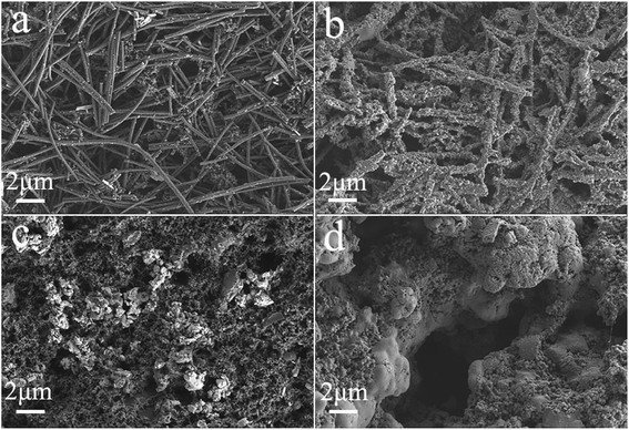 | ||
| Fig. 5 SEM images of Fe7Se8-NCFs and Fe7Se8: (a and c) before cycling; (b and d) after 100 cycles in the charged state, respectively. | ||
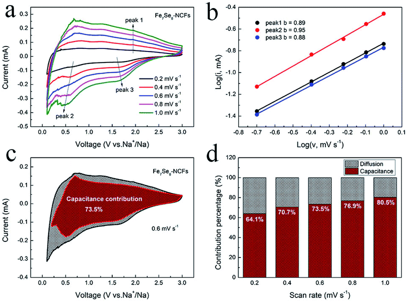
Fig. 6 displays the kinetics analysis of Fe7Se8-NCFs to understand the promising rate performance in sodium storage. When the scan rate increases from 0.2 to 1 mV s−1, the CV curves of Fe7Se8-NCFs and Fe7Se8 show a similar shape (Fig. 6a and S7a†). The current (i) and scan rate (v) conform to the equation as follows:30,31
| i = avb | (1) |
log(i) = log(a) + b![[thin space (1/6-em)]](https://www.rsc.org/images/entities/char_2009.gif) log(v) log(v) | (2) |
The b value is the slope of eqn (2), which is in the range from 0.5 to 1. In general, a b value of 0.5 or 1 represents a capacitive-controlled or diffusion-controlled process. For Fe7Se8-NCFs, the b value of oxidation and reduction peaks is calculated to be 0.89, 0.95 and 0.88, higher than those of Fe7Se8 (0.51, 0.51 and 0.55) (Fig. 6b and S7b†). All b values of Fe7Se8-NCFs are close to 1, which suggests mainly pseudocapacitive behavior in redox reactions. On the other hand, we calculated the ratio of pseudocapacitive contribution according to the following equation:32,33
| i = k1υ + k2υ1/2 | (3) |
| i/υ1/2 = k1υ1/2 + k2 | (4) |
In view of the impressive performance of Fe7Se8-NCFs in half cells, a sodium ion full cell was fabricated to explore its practical feasibility. The Fe7Se8-NCF anode was coupled with an excessive NVP cathode to assemble the full cell. The SEM morphology, the XRD pattern and sodium storage performance of NVP are provided in Fig. S9.† The charge/discharge curves of NVP display a voltage plateau of 3.3 V in the half cell (Fig. 7a). The NVP in the half cell delivers a stable specific capacity of 99 mA h g−1 after 100 cycles and a favorable rate performance of 81 mA h g−1 at a high rate of 2 A g−1, which is in good agreement with previous research.35 Based on the weight of the Fe7Se8-NCF anode, we examined the electrochemical performance of the NVP‖Fe7Se8-NCF sodium ion full cell. The charge/discharge curves of the NVP‖Fe7Se8-NCF full cell between 0.5 and 3.5 V are obtained, which exhibits an initial charge/discharge capacity of 685/279 mA h g−1 with an ICE of 40.7% (Fig. 7b). The low ICE may be attributed to the formation of a SEI film and some irreversible reactions.36 The cycling and rate capability of the NVP‖Fe7Se8-NCF full cell are evaluated as shown in Fig. 7c and d. The specific capacity of the full cell remains at 109 mA h g−1 at 1 A g−1 with a CE of ∼100% after 200 cycles. Moreover, the NVP‖Fe7Se8-NCF full cell exhibits favorable rate performance with a specific capacity of 136 mA h g−1 at 2 A g−1. These results demonstrate the application potential of Fe7Se8-NCFs in sodium ion batteries.
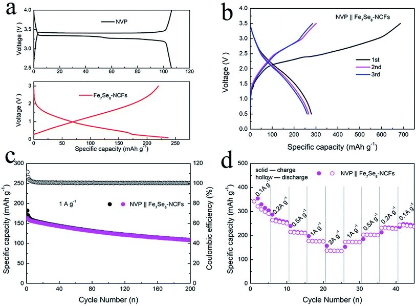 | ||
| Fig. 7 (a) Charge/discharge curves of NVP and Fe7Se8-NCF electrodes in a half-cell. (b) Charge/discharge curves, and (c) cycling and (d) rate performance of the NVP‖Fe7Se8-NCF full cell. | ||
Conclusion
In conclusion, unique Fe7Se8 embedded in carbon nanofibers was successfully designed for sodium storage. In consideration of the 1D carbon nanofiber network, Fe7Se8-NCFs can facilitate Na+ transportation by increasing the contact area between the electrode and electrolyte to promote electrochemical reaction kinetics. Moreover, Fe7Se8 encapsulated in carbon nanofibers, the Fe7Se8-NCF electrode, can effectively accommodate the volume change to keep the structural integrity of Fe7Se8-NCFs during a conversion reaction process. Hence, the Fe7Se8-NCF electrode shows remarkable stability (223 mA h g−1 at 0.1 A g−1, after 400 cycles) and improved rate capability (153 mA h g−1, 2 A g−1) in half-cells. Impressively, when coupled with NVP to assemble a full cell, the NVP‖Fe7Se8-NCF full cell exhibits its practical feasibility with a specific capacity of 109 mA h g−1 after 200 cycles (1 A g−1) and a favorable rate capability of 136 mA h g−1 at a high rate of 2 A g−1.Conflicts of interest
There are no conflicts to declare.Acknowledgements
This work was financially supported by the Natural Science Foundation of Guangdong Province (2018A030313739) and Science and Technology Program of Guangzhou (No. 2019050001).References
- Y. Jiang, D. Song, J. Wu, Z. Wang, S. Huang, Y. Xu, Z. Chen, B. Zhao and J. Zhang, Sandwich-like SnS2/graphene/SnS2 with expanded interlayer distance as high-rate lithium/sodium-ion battery anode materials, ACS Nano, 2019, 13, 9100–9111 CrossRef CAS
.
- L. Fu, Z. Bi, B. Wei, L. Huang, X. Zhang, Z. Chen, H. Liao, M. Li, C. Shang and X. Wang, Flower-like Cu2SnS3 Nanostructure Materials with High Crystallinity for Sodium Storage, Nanomaterials, 2018, 8, 475 CrossRef
.
- S. Wang, L. Xia, L. Yu, L. Zhang, H. Wang and X. W. D. Lou, Free-Standing Nitrogen-Doped Carbon Nanofiber Films: Integrated Electrodes for Sodium-Ion Batteries with Ultralong Cycle Life and Superior Rate Capability, Adv. Energy Mater., 2016, 6, 1502217 CrossRef
.
- Y. Fang, B. Y. Guan, D. Luan and X. W. D. Lou, Synthesis of CuS@CoS2 Double-Shelled Nanoboxes with Enhanced Sodium Storage Properties, Angew. Chem., Int. Ed., 2019, 58, 7739–7743 CrossRef CAS
.
- C. Guo, W. Zhang, Y. Liu, J. He, S. Yang, M. Liu, Q. Wang and Z. Guo, Constructing CoO/Co3S4 Heterostructures Embedded in N-doped Carbon Frameworks for High Performance Sodium-Ion Batteries, Adv. Funct. Mater., 2019, 29, 1901925 CrossRef
.
- Z. Hu, Q. Liu, W. Lai, Q. Gu, L. Li, M. Chen, W. Wang, S. L. Chou, Y. Liu and S. X. Dou, Manipulating Molecular Structure and Morphology to Invoke High-Performance Sodium Storage of Copper Phosphide, Adv. Energy Mater., 2020, 10, 1903542 CrossRef CAS
.
- X. Li, M. Sun, J. Ni and L. Li, Template-Free Construction of Self-Supported Sb Prisms with Stable Sodium Storage, Adv. Energy Mater., 2019, 9, 1901096 CrossRef
.
- L. Fu, X. Zheng, L. Huang, C. Shang, K. Lu, X. Zhang, B. Wei and X. Wang, Synthesis and Investigation of CuGeO3 Nanowires as Anode Materials for Advanced Sodium-Ion Batteries, Nanoscale Res. Lett., 2018, 13, 193 CrossRef
.
- H. Li, K. Wang, M. Zhou, W. Li, H. Tao, R. Wang, S. Cheng and K. Jiang, Facile Tailoring of Multidimensional Sb for Sodium Storage Applications, ACS Nano, 2019, 13, 9533–9540 CrossRef CAS
.
- Y. Wang, Y. Wang, Y. X. Wang, X. Feng, W. Chen, J. Qian, X. Ai, H. Yang and Y. Cao,
In Situ Formation of Co9S8 Nanoclusters in Sulfur-Doped Carbon Foam as a Sustainable and High-Rate Sodium-Ion Anode, ACS Appl. Mater. Interfaces, 2019, 11, 19218–19226 CrossRef CAS
.
- K. Zhang, Z. Hu, X. Liu, Z. Tao and J. Chen, FeSe2 Microspheres as a High-Performance Anode Material for Na-Ion Batteries, Adv. Mater., 2015, 27, 3305–3309 CrossRef CAS
.
- D. M. Zhang, J. H. Jia, C. C. Yang and Q. Jiang, Fe7Se8 nanoparticles anchored on N-doped carbon nanofibers as high-rate anode for sodium-ion batteries, Energy Storage Materials, 2020, 24, 439–449 CrossRef
.
- J. Xia, L. Liu, S. Jamil, J. Xie, H. Yan, Y. Yuan, Y. Zhang, S. Nie, J. Pan, X. Wang and G. Cao, Free-standing SnS/C nanofiber anodes for ultralong cycle-life lithium-ion batteries and sodium-ion batteries, Energy Storage Materials, 2019, 17, 1–11 CrossRef
.
- Z. Sun, X. Wu, Z. Gu, P. Han, B. Zhao, D. Qu, L. Gao, Z. Liu, D. Han and L. Niu, Rationally designed nitrogen-doped yolk–shell Fe7Se8/carbon nanoboxes with enhanced sodium storage in half/full cells, Carbon, 2020, 166, 175–182 CrossRef CAS
.
- J. Xia, Y. Yuan, H. Yan, J. Liu, Y. Zhang, L. Liu, S. Zhang, W. Li, X. Yang, H. Shu, X. Wang and G. Cao, Electrospun SnSe/C nanofibers as binder-free anode for lithium-ion and sodium-ion batteries, J. Power Sources, 2020, 449, 227559 CrossRef CAS
.
- C. Shang, S. Dong, S. Zhang, P. Hu, C. Zhang and G. Cui, A Ni3S2-PEDOT monolithic electrode for sodium batteries, Electrochem. Commun., 2015, 50, 24–27 CrossRef CAS
.
- J. Zhang, Y. Liu, H. Liu, Y. Song, S. Sun, Q. Li, X. Xing and J. Chen, Urchin-Like Fe3Se4 Hierarchitectures: A Novel Pseudocapacitive Sodium-Ion Storage Anode with Prominent Rate and Cycling Properties, Small, 2020, 16, 2000504 CrossRef CAS
.
- J. Li, J. Zhao, R. Tang, Q. Chen, Z. Niu, M. Li, C. Guo, J. Su and L. Zhang, Facilely fabricating FeSe nanoparticles embedded in N-doped carbon towards promoting sodium storage behaviors, J. Power Sources, 2020, 449, 227517 CrossRef CAS
.
- X. Hu, Y. Liu, J. Li, G. Wang, J. Chen, G. Zhong, H. Zhan and Z. Wen, Self-Assembling of Conductive Interlayer-Expanded WS2 Nanosheets into 3D Hollow Hierarchical Microflower Bud Hybrids for Fast and Stable Sodium Storage, Adv. Funct. Mater., 2019, 30, 1907677 CrossRef
.
- L. Hu, L. He, X. Wang, C. Shang and G. Zhou, MnSe embedded in carbon nanofibers as advanced anode material for sodium ion batteries, Nanotechnology, 2020, 31, 335402 CrossRef CAS
.
- T. Liu, Y. Li, L. Zhao, F. Zheng, Y. Guo, Y. Li, Q. Pan, Y. Liu, J. Hu and C. Yang,
In Situ Fabrication of Carbon-Encapsulated Fe7X8 (X = S, Se) for Enhanced Sodium Storage, ACS Appl. Mater. Interfaces, 2019, 11, 19040–19047 CrossRef CAS
.
- Z. Man, P. Li, D. Zhou, Y. Wang, X. Liang, R. Zang, P. Li, Y. Zuo, Y. M. Lam and G. Wang, Two Birds with One Stone: FeS2@C Yolk–Shell Composite for High-Performance Sodium-Ion Energy Storage and Electromagnetic Wave Absorption, Nano Lett., 2020, 20, 3769–3777 CrossRef CAS
.
- Y. He, M. Luo, C. Dong, X. Ding, C. Yin, A. Nie, Y. Chen, Y. Qian and L. Xu, Coral-like NixCo1−xSe2 for Na-ion battery with ultralong cycle life and ultrahigh rate capability, J. Mater. Chem. A, 2019, 7, 3933–3940 RSC
.
- H. Yang, R. Xu, Y. Yao, S. Ye, X. Zhou and Y. Yu, Multicore-Shell Bi@N-doped Carbon Nanospheres for High Power Density and Long Cycle Life Sodium-and Potassium-Ion Anodes, Adv. Funct. Mater., 2019, 29, 1809195 CrossRef
.
- M. Wan, R. Zeng, K. Chen, G. Liu, W. Chen, L. Wang, N. Zhang, L. Xue, W. Zhang and Y. Huang, Fe7Se8 nanoparticles encapsulated by nitrogen-doped carbon with high sodium storage performance and evolving redox reactions, Energy Storage Materials, 2018, 10, 114–121 CrossRef
.
- H. Wu, X. Chen, C. Qian, H. Yan, C. Yan, N. Xu, Y. Piao, G. Diao and M. Chen, Confinement Growth of Layered WS2 in Hollow Beaded Carbon Nanofibers with Synergistic Anchoring Effect to Reinforce Li+/Na+ Storage Performance, Small, 2020, 16, 2000695 CrossRef CAS
.
- Z. Li, Y. Fang, J. Zhang and X. W. D. Lou, Necklace-Like Structures Composed of Fe3N@C Yolk–Shell Particles as an Advanced Anode for Sodium-Ion Batteries, Adv. Mater., 2018, 30, 1800525 CrossRef
.
- M. Yousaf, Y. Wang, Y. Chen, Z. Wang, A. Firdous, Z. Ali, N. Mahmood, R. Zou, S. Guo and R. P. S. Han, A 3D Trilayered CNT/MoSe2/C Heterostructure with an Expanded MoSe2 Interlayer Spacing for an Efficient Sodium Storage, Adv. Energy Mater., 2019, 9, 1900567 CrossRef
.
- W. Tian, W. Ma, Z. Feng, F. Tian, H. Li, J. Liu and S. Xiong, Formation of hierarchical Fe7Se8 nanorod bundles with enhanced sodium storage properties, J. Energy Chem., 2020, 44, 97–105 CrossRef
.
- L. Hu, C. Shang, L. Huang, X. Wang and G. Zhou, Cu3Ge coated by nitrogen-doped carbon nanorods as advanced sodium-ion battery anodes, Ionics, 2019, 26, 719–726 CrossRef
.
- C. C. Li, B. Wang, D. Chen, L. Y. Gan, Y. Feng, Y. Zhang, Y. Yang, H. Geng, X. Rui and Y. Yu, Topotactic Transformation Synthesis of 2D Ultrathin GeS2 Nanosheets toward High-Rate and High-Energy-Density Sodium-Ion Half/Full Batteries, ACS Nano, 2020, 14, 531–540 CrossRef CAS
.
- P. Liu, J. Han, K. Zhu, Z. Dong and L. Jiao, Heterostructure SnSe2/ZnSe@PDA Nanobox for Stable and Highly Efficient Sodium-Ion Storage, Adv. Energy Mater., 2020, 10, 2000741 CrossRef CAS
.
- J. Wang, B. Wang, X. Liu, J. Bai, H. Wang and G. Wang, Prussian blue analogs (PBA) derived porous bimetal (Mn, Fe) selenide with carbon nanotubes as anode materials for sodium and potassium ion batteries, Chem. Eng. J., 2020, 382, 123050 CrossRef CAS
.
- X. Wang, X. Li, Q. Li, H. Li, J. Xu, H. Wang, G. Zhao, L. Lu, X. Lin, H. Li and S. Li, Improved Electrochemical Performance Based on Nanostructured SnS2@CoS2-rGO Composite Anode for Sodium-Ion Batteries, Nano-Micro Lett., 2018, 10, 46 CrossRef
.
- S. Shi, C. Sun, X. Yin, L. Shen, Q. Shi, K. Zhao, Y. Zhao and J. Zhang, FeP Quantum Dots Confined in Carbon-Nanotube-Grafted P-Doped Carbon Octahedra for High-Rate Sodium Storage and Full-Cell Applications, Adv. Funct. Mater., 2020, 30, 1909283 CrossRef CAS
.
- Z. Ali, M. Asif, X. Huang, T. Tang and Y. Hou, Hierarchically Porous Fe2CoSe4 Binary-Metal Selenide for Extraordinary Rate Performance and Durable Anode of Sodium-Ion Batteries, Adv. Mater., 2018, 1802745 CrossRef
.
Footnotes |
| † Electronic supplementary information (ESI) available. See DOI: 10.1039/d0na00897d |
| ‡ These authors contributed equally. |
| This journal is © The Royal Society of Chemistry 2021 |

