
 Open Access Article
 This Open Access Article is licensed under a Creative Commons Attribution-Non Commercial 3.0 Unported Licence
Hydrothermal syntheses, luminescent properties, and temperature sensing of monodisperse Tb-doped NaCeF4 nanocrystals†
Haoran
Qin
ab,
Xinghong
Gong
 a,
Zundu
Luo
a and
Yidong
Huang
*a
a,
Zundu
Luo
a and
Yidong
Huang
*a
aKey Laboratory of Optoelectronic Materials Chemistry and Physics, Fujian Institute of Research on the Structure of Matter, Chinese Academy of Sciences, Fuzhou, Fujian 350002, China. E-mail: huyd@fjirsm.ac.cn
bUniversity of Chinese Academy of Sciences, Beijing 100039, China
First published on 28th November 2020
Abstract
Monodisperse Tb-doped NaCeF4 nanocrystals were synthesized via a hydrothermal method. The morphology, and room temperature and temperature dependent luminescent properties were investigated. Excited at 254 nm, the emissions of Ce3+ at 270–370 nm and those of Tb3+ at 475–700 nm can be observed. The strongest visible emission was observed in NaCeF4:20 at% Tb with a quantum yield of 49%. The efficiency of energy transfer from Ce3+ to Tb3+ increases with the Tb3+ doping concentration and reaches 95% for NaCeF4:30 at% Tb. The ratio of Tb3+ emission to Ce3+ emission is sensitive to temperature, and the relative sensitivity was calculated to be 1.0% °C−1 at 60 °C. The mechanisms for this thermal dependence were analyzed in terms of non-radiative relaxation and energy migration.
Introduction
Lanthanide doped nano-fluorides have gained increasing attention due to their high chemical stability and high resistance to photobleaching.1 Doped lanthanides give nanocrystals (NCs) unique f–f emission peaks and long fluorescence lifetimes.2,3 These properties make lanthanide doped NCs appliable for biological labelling,4 displays,5,6 solar cells,7etc. A nano hexagonal β-NaReF4 (Re = Y, La–Lu) system as a host for a luminescent temperature probe is mainly due to its good chemical and physical stability and highly efficient up-conversion and downshifting photoluminescence.8,9Lanthanide ion Ce3+ possesses low 4f–5d multiplets and simple 4f multiplets and is widely applied for lanthanide luminescence.10,11 Some monodisperse and well-defined NaCeF4 based NCs have been synthesized. Lei et al. synthesized NaCeF4:Er3+/Yb3+ NCs via the high temperature coprecipitation method.12 Li et al. synthesized NaCeF4 NCs via the liquid–solid-solution hydrothermal method.13
Ce3+ ions possess broad absorption and emission bands with large cross-sections due to the high oscillator strength of parity allowed 4f–5d transition. The Tb3+ ion possesses green emission with a long fluorescence lifetime (millisecond scale), and has been applied for time-resolved photoluminescence imaging.14 However, the absorption of excitation light by Tb3+ is weak because the corresponding 4f–4f transitions are all parity and spin forbidden. Efficient energy transfer (ET) from Ce3+ to Tb3+ and bright green emission have been reported in many Ce3+ & Tb3+ co-doped materials,15–18 which inspired researchers to adopt Ce3+ and Tb3+ combination in nanomaterials. These materials can downshift ultra violet (UV) light to visible light to overcome the poor response of photovoltaic (PV) devices to short wavelength light.19,20 Lian et al. synthesized NaCeF4 and NaCeF4:Tb3+ NCs via the thermal decomposition method,21 and investigated their photoluminescence properties. The NCs synthesized via thermal decomposition are monodisperse and highly crystalline.22 However the thermal decomposition method operates at high temperature (about 300 °C).23 Here we synthesized NaCeF4:Tb3+ NCs by a hydrothermal method.24 With this method, the reaction operates at low temperature (below 200 °C) and monodisperse NCs were successfully synthesized.
Moreover, the 5d–4f emission of Ce3+ is sensitive to temperature,25 while the 4f–4f emission of Tb3+ is not, which may be because the 4f multiplets are shielded by outer 5s and 5p multiplets.26 With the different responses to temperature between Ce3+ and Tb3+, their fluorescence intensity ratio (FIR) may act as a probe for temperature sensing. Some Ce3+ & Tb3+ co-doped phosphors have been investigated.27–29 However, investigations on Ce3+ and Tb3+ induced FIR temperature sensing in NCs are rare.
In this article, we synthesized NaCeF4:Tb3+ NCs by a hydrothermal method. The morphology and structure of NaCeF4:Tb NCs were investigated. Furthermore, room temperature (RT) and temperature dependent luminescent properties of NaCeF4:Tb NCs were studied. The materials are monodispersed and exhibit bright emission and a high quantum yield, and may have potential application for enhancing the energy conversion efficiency of PV devices. Moreover, since the FIR between Ce3+ and Tb3+ emission correlates strongly with temperature, NaCeF4:Tb NCs may have potential application in FIR nano-thermometers.
Experimental
Materials
Ce(NO3)3·6H2O, Tb(NO3)3·5H2O, oleic acid (OA), sodium hydroxide, ammonium fluoride, and cyclohexane were purchased from the Aladdin Chemical Reagent Company. Ethanol was purchased from the Sinopharm Chemical Reagent Company. All the chemicals were of analytical grade and used without further purification. Deionized water was used throughout the experiments.Synthesis
Typically, for synthesis of NaCeF4 NCs, 1.5 ml H2O, 0.6 g sodium hydroxide, 20 ml OA, and 10 ml ethanol were mixed. Then 0.5 mmol Ce(NO3)3 (0.5 M) aqueous solution was added into the above solution. Lastly, 3 mmol ammonium fluoride aqueous solution (2 M) was added into the mixed solution. After stirring for 30 min, the colloidal solution was transferred into a 50 ml Teflon-lined autoclave and was heated at selected 170 °C for 6 h. The systems were then cooled down to room temperature. The final products were collected by centrifugation, washed with ethanol, and then dispersed in cyclohexane. The doping of Tb3+ was conducted by adding Tb(NO3)3 with designed concentrations to the reaction system.Characterization
X-ray diffraction (XRD) analysis was carried out on a Rigaku-Dmax 2500 diffractometer using Cu-Kα radiation (λ = 0.154 nm). The size and morphology of the samples were observed using a transmission electron microscope (TEM) JEOL-2010 equipped with an energy dispersive X-ray spectrometer (EDS). Fourier-transform infrared (FTIR) spectra were recorded in KBr discs using a Magna 750 FTIR spectrometer. The temperature dependent and RT emission, RT excitation spectra, quantum yield, and RT fluorescence decay curves were recorded from pressed tablets of the NaCeF4:Tb NCs powder using an FLS 980, Edinburgh.Results and discussion
Components and morphology
The XRD patterns of NaCeF4 NCs with different Tb3+ doping concentrations match well with those of β-NaCeF4 (pdf#50-0154) (ESI Fig. S1†). No additional phases were found even in the sample with 30 at% Tb3+ doping, indicating that Tb3+ has been efficiently incorporated into the host of β-NaCeF4. The EDS pattern of NaCeF4:20 at% Tb is shown in ESI Fig. S2.† The results of XRD and EDS analyses reveal high purity of the as-prepared samples. OA was chosen as the capping agent to control the growth of NCs and make NCs non-polar solvent soluble. The as-prepared NCs can be well dispersed in cyclohexane and the solution is transparent (ESI Fig. S3(a)†). The presence of OA capping on the surface of the NaCeF4 NCs was verified from the FTIR spectrum (ESI Fig. S3(b)†).The TEM pattern of NaCeF4:20 at% Tb NCs is shown in Fig. 1. The shape and size of the asprepared NCs can be seen in Fig. 1(a–c); the NCs are a hexagonal prism and monodisperse. The length of NCs is parallel to the hexad axis, and hence the crystal growth direction is [001]. The length of NaCeF4:20 at% Tb NCs has been estimated by randomly analysing 200 NCs. The mean length of the NCs is 170 nm and the distribution frequency of the lengths can be seen in Fig. 1(d), which shows good uniformity of the NCs. The cross-section diameters of the NCs are about 45 nm. The aspect ratio of the NCs was therefore calculated to be 3.8. From the high resolution TEM (HRTEM) image of the NC pattern shown in Fig. 1(e), clear lattice fringes can be observed, which indicate good crystallinity. Fig. 1(f) shows the Fourier transform image of the square area in Fig. 1(e). In Fig. 1(g), two interplanar distances were labelled 0.532 and 0.327 nm, which are in accordance with the (100) and (101) interplanar distances of NaCeF4,30 respectively.
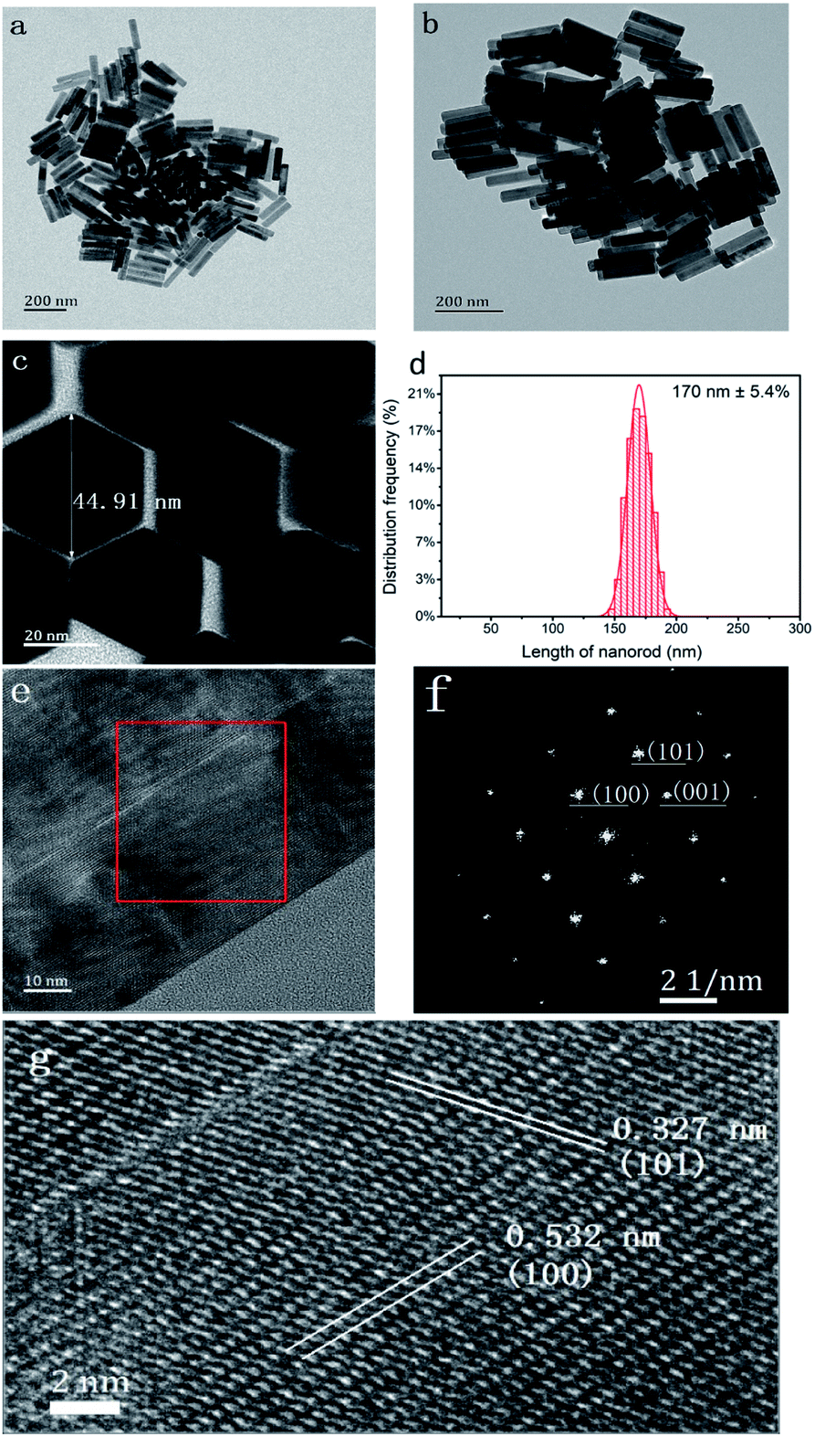 | ||
| Fig. 1 (a and b) TEM images of NaCeF4:20 at% Tb NCs. (c) HRTEM image of the NCs. (d) Distribution frequency of the lengths of the NCs. (e) HRTEM image of the NCs. (f) Fourier transform image of the square area in (e). (g) Zoom in of the square area in (e) with the labelled interplanar spacing. | ||
Luminescent properties
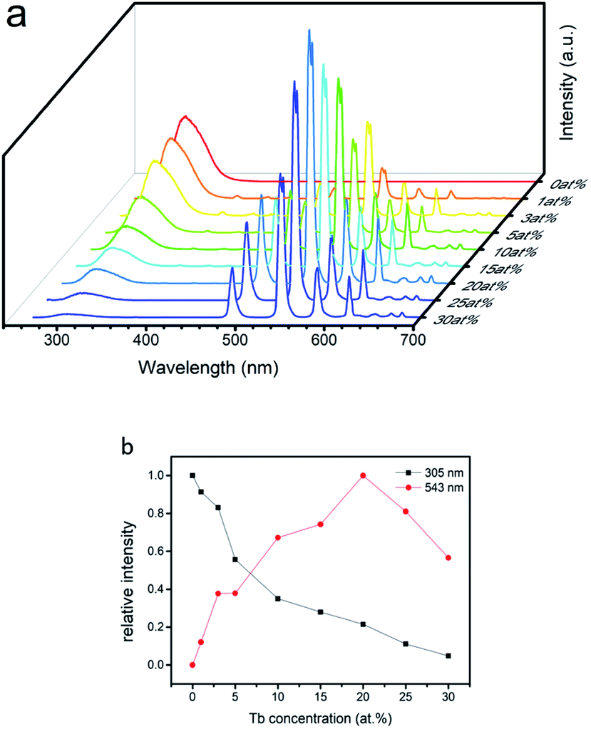
The excitation spectra of the NaCeF4:Tb NCs are similar, and the excitation spectrum of the NaCeF4:20 at% Tb monitoring emission at 543 nm is shown in Fig. 2. There are two types of excitation signals in Fig. 2. The broad and strong band originates mainly from the parity-allowed 4f–5d transitions of Ce3+, and the narrow and weak peaks come from the parity-forbidden 4f–4f transitions from the ground state to the corresponding excited multiplets of Tb3+. The strong band is centered at 256 nm and matches well with a commercial low-pressure mercury lamp with a central wavelength of 254 nm. Under excitation of the lamp, the cyclohexane solution with NaCeF4:20 at% Tb NCs dispersed emits bright green fluorescence (ESI Fig. S4†). Under excitation at 254 nm, the emission spectra of the NaCeF4 NCs with different Tb doping concentrations are shown in Fig. 3(a). The emission spectra for different samples were measured under the same conditions. The broad emission bands around 305 nm originate from the 5d–4f transition of Ce3+. The emission peaks centered at 489, 543, 584, and 620 nm are the 4f–4f transitions from 5D4 to 7F6,5,4,3 multiplets of Tb3+, respectively. Fig. 3(b) shows the changes of fluorescence intensities at 305 and 543 nm with the Tb doping concentration. Fluorescence intensity at 305 nm decreases with the increase of the Tb concentration, which indicates the existence of the ET process from Ce3+ to Tb3+. The Ce3+ emission ranges from 275 to 360 nm, which overlaps with some excited levels of Tb3+ (ESI Fig. S5†). Hence the ET from Ce3+ to Tb3+ is resonant. The ET efficiency can be expressed by the following equation:31where IS and IS0 are the integrated fluorescence intensities (270–370 nm) of Ce3+ with and without Tb3+ doping, respectively. The ET efficiency for the NaCeF4:xat% Tb NCs (x = 1, 3, 5, 10, 15, 20, 25, 30) was therefore calculated to be 10%, 16%, 45%, 63%, 71%, 78%, 88%, and 95%, respectively. In Fig. 3, the sample with 20 at% Tb doping shows the strongest visible emission and the visible quantum yield was measured to be 49%. With the Tb doping concentration being increased further, the intensity of Tb emission decreases, which indicates the presence of concentration dependent fluorescence quenching in the NCs.
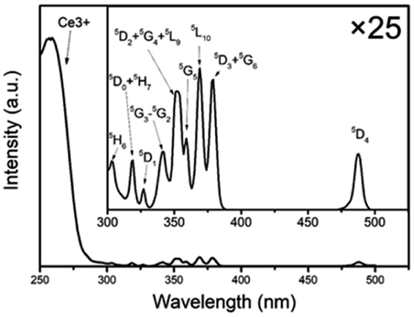 | ||
| Fig. 2 Excitation spectrum of NaCeF4:20 at% Tb NCs monitoring at Tb3+ 5D4 → 7F5 transition (λem = 543 nm). The inset spectrum is intensity magnified 25 times the one in the range from 300 to 550 nm. | ||
 | ||
| Fig. 3 (a) Emission spectra of NaCeF4:Tb NCs under excitation at 254 nm. (b) Fluorescence intensity at 305 and 543 nm versus the Tb concentration. | ||
Fluorescence decay curves at 543 nm for NaCeF4 NCs with different Tb doping concentrations were measured under excitation at 254 nm. The results on a semilog coordinate are depicted in Fig. 4. Obviously, the curves exhibit simple exponential decay behaviour and can be expressed by
I=I0![[thin space (1/6-em)]](https://www.rsc.org/images/entities/char_2009.gif) exp(−t/τ) exp(−t/τ) |
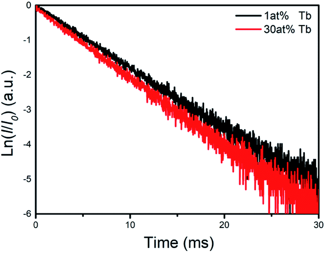 | ||
| Fig. 4 Semi-logarithmic coordinates of the fluorescence decay curves of Tb3+ 5D4 →7F5 transition (λem = 543 nm) under excitation at 254 nm for the sample with different Tb doping concentrations. | ||
Temperature sensing behaviour
NaCeF4:5 at% Tb NCs exhibit high and similar Ce and Tb emission intensities, which are suitable for temperature sensing.32 The temperature dependent fluorescence spectra of NaCeF4:5 at% Tb NCs under excitation at 254 nm are shown in Fig. 5(a). The trends of the temperature dependent emission intensity of Ce3+ and Tb3+ are different. ICe is defined as the integrated Ce3+ emission intensity in the range of 270–370 nm. ITb and ITb green are defined as the integrated Tb3+ emission intensities in the ranges of 475–700 nm and 525–570 nm, respectively. As shown in Fig. 5(b), when the temperature is below 0 °C, ICe remains unchanged (100% ± 2%); when the temperature is higher than 0 °C, ICe decreases with temperature rise and to 83% at 60 °C. However, bot ITb and ITb green increase with the temperature to about 150% at 60 °C. Based on the Ce3+ configuration coordinate diagram shown in Fig. 6, the trend of temperature dependent ICe can be partially explained. The nonradiative transition (process A) needs assistance of phonons to pass through an energy barrier ΔE to the 4f ground states,33 and hence increasing the temperature will promote this nonradiative transition34 and decrease the overall quantum efficiency. The temperature dependent luminescence spectra of NaCeF4 NCs can be seen in ESI Fig. S6.† ΔE was calculated to be 0.41 eV according to the Arrhenius formula. For materials with a high Ce3+ concentration, there is another temperature quenching mechanism: thermally activated concentration quenching.35 This mechanism depends on the thermally enhanced nonradiative energy migration among Ce3+ and then transfer to defects.36 For Tb3+ and Ce3+ co-doped materials, the defects could also be Tb3+. Hence, Tb3+ emission could be thermally enhanced in materials with a high Ce3+ concentration. NaCeF4:Tb3+ possesses a high Ce3+ concentration, and hence temperature sensitivity may be higher than those with a low Ce3+ concentration.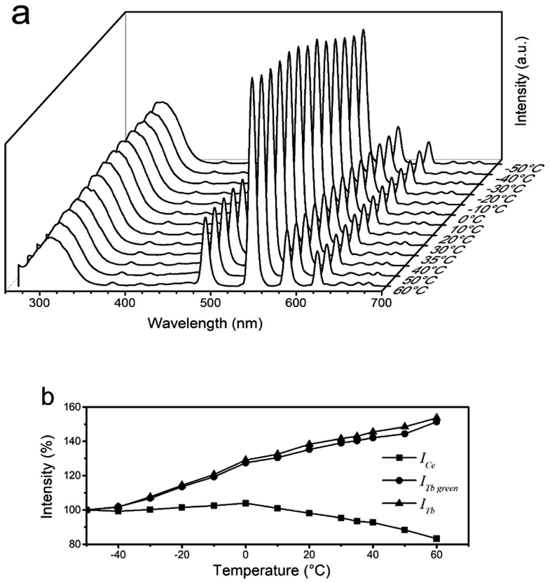 | ||
| Fig. 5 (a) Temperature dependent luminescence spectra of NaCeF4:5 at% Tb NCs. (b) Integrated luminescence intensity versus temperature. | ||
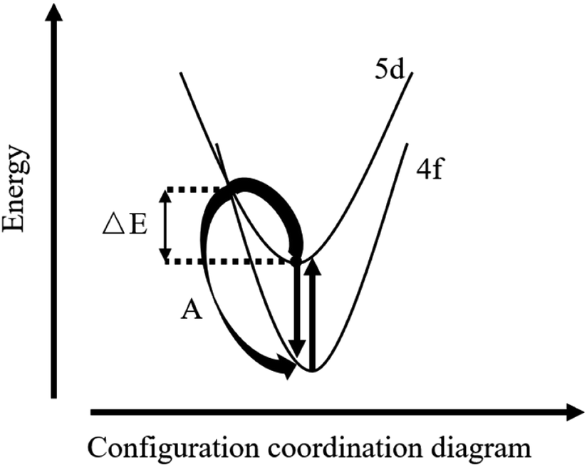 | ||
| Fig. 6 Ce3+ configuration coordinate diagram. | ||
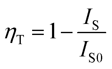
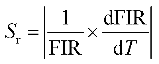
As illustrated in Fig. 7(a and b), both the FIRs ITb/ICe and ITb green/ICe increased monotonously and nonlinearly with temperature. The experimental values in Fig. 7(a and b) can be fitted well with single exponential curves; the relevant expressions are shown as insets in Fig. 7(a and b), respectively. Repeatability and stability are important for practical application of thermometers. Six cycles of heating–cooling experiments were thus conducted, and the results are shown in Fig. 7(c and d). The results indicate that ITb/ICe and ITb green/ICe are reversible and stable. The absolute and relative sensitivity (Sa, Sr) can be expressed as42
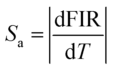
where T is the temperature. The calculated Sa and Srversus temperature were plotted in Fig. 7(e and f). The values of Sr for ITb/ICe and ITb green/ICe below 40 °C are similar. When the temperature exceeds 40 °C, the Sr of ITb/ICe is larger than that of ITb green/ICe. The maximum Sr of ITb/ICe and ITb green/ICe reaches 1.0% °C−1 and 0.9% °C−1 at 60 °C, respectively, and the values may be higher at a higher temperature. In Table 1, compared with others, the tendency of the ICe/ITb ratio with temperature for NaCeF4:5% Tb is unique and NaCeF4:5% Tb has the highest Sr, which may be ascribed to its highest Ce3+ concentration. The high temperature sensitivity and high stability indicate that this NC could be a candidate for use as a UV-excited luminescence ratio metric nanothermometer.
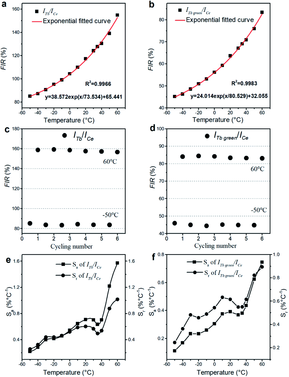 | ||
| Fig. 7 For NaCeF4:5 at% Tb NCs. (a and b) Temperature dependent fluorescence intensity ratio with exponential fitted curves (ITb/ICe for (a); ITb green/ICe for (b)). (c and d) ITb/ICe and ITb green/ICe in heating–cooling cycles. (e and f) Temperature dependent absolute sensitivity (Sa) and relative sensitivity (Sr) (ITb/ICe for (e); ITb green/ICe for (f)). | ||
| Ce & Tb activated thermometers | Ce3+ concentration (1020 cm−3) | Tendency of the ICe/ITb ratio with temperature | Temperature range (°C) | Sr (% °C−1) | Ref. |
|---|---|---|---|---|---|
| YBO3:1% Ce,1% Tb | 1.8 | Linear | 15–55 | 0.498 | 37 |
| β-NaYF4:10% Ce,5% Tb | 12.2 | Linear | 30–290 | 0.65 | 38 |
| LaOBr: 1% Ce,3% Tb | 1.6 | Linear | 20–160 | 0.42 | 27 |
| K2BaCa(PO4)2:3% Ce,3% Tb | 3.0 | Linear | 20–200 | 0.35 | 39 |
| Sr30.6Ce(PO4)3:40% Tb | 22.7 | Linear | 25–300 | 0.384 | 40 |
| BaY2Si3O10:2% Ce,18% Tb | 1.9 | Linear | 20–260 | 0.30 | 41 |
| NaCeF4:5% Tb | 112.6 | Nonlinear | −50 to 60 | 1.0 | This work |
Conclusion
Monodisperse Tb doped NaCeF4 NCs with high crystallinity and high uniformity have been prepared via a hydrothermal method. Under excitation at 254 nm, the NCs exhibit UV emission of Ce3+ and characteristic visible emission of Tb3+. Fluorescence spectra show the existence of ET from Ce3+ to Tb3+, and NaCeF4:20 at% Tb displays the strongest visible emission with a quantum yield of 49%. The temperature dependent fluorescence spectra of NaCeF4:5 at% Tb indicate that the ratio of Tb emission to Ce emission increases monotonously with temperature. Compared with other Ce & Tb thermometers, the Tb doped NaCeF4 NCs have higher maximum Sr, which may be ascribed to the high Ce3+ concentration in the NCs. Due to the uniform nanomorphology, unique luminescent properties and high temperature sensitivity, the Tb doped NaCeF4 NCs may have applications in PV devices and FIR nanothermometers.Conflicts of interest
There are no conflicts to declare.Acknowledgements
This work has been supported by the National Natural Science Foundation of China (Grant 51772290).References
- T. Cheng, R. Marin, A. Skripka and F. Vetrone, J. Am. Chem. Soc., 2018, 140, 12890–12899 CrossRef CAS PubMed.
- J. Liu, A. M. Kaczmarek and R. Van Deun, Chem. Soc. Rev., 2018, 47, 7225–7238 RSC.
- K. Y. Zhang, Q. Yu, H. Wei, S. Liu, Q. Zhao and W. Huang, Chem. Rev., 2018, 118, 1770–1839 CrossRef CAS PubMed.
- Q. Ma, J. Wang, Z. Li, X. Lv, L. Liang and Q. Yuan, Small, 2019, 15, 1804969 CrossRef PubMed.
- F. Wang, Y. Han, C. S. Lim, Y. Lu, J. Wang, J. Xu, H. Chen, C. Zhang, M. Hong and X. Liu, Nature, 2010, 463, 1061–1065 CrossRef CAS PubMed.
- W. Song, H. Choi, Y. Kim and H. Yang, J. Mater. Chem., 2010, 20, 6929–6934 RSC.
- J. Roh, H. Yu and J. Jang, ACS Appl. Mater. Interfaces, 2016, 8, 19847–19852 CrossRef CAS PubMed.
- W. You, D. Tu, W. Zheng, X. Shang, X. Song, S. Zhou, Y. Liu, R. Li and X. Chen, Nanoscale, 2018, 10, 11477–11484 RSC.
- D. Peng, Q. Ju, X. Chen, R. Ma, B. Chen, G. Bai, J. Hao, X. Qiao, X. Fan and F. Wang, Chem. Mater., 2015, 27, 3115–3120 CrossRef CAS.
- Q. Yao, P. Hu, P. Sun, M. Liu, R. Dong, K. Chao, Y. Liu, J. Jiang and H. Jiang, Adv. Mater., 2020, 32, 1907888 CrossRef CAS PubMed.
- B. Zhou, J. Huang, L. Yan, X. Liu, N. Song, L. Tao and Q. Zhang, Adv. Mater., 2019, 31, 1806308 Search PubMed.
- X. Lei, R. Li, D. Tu, X. Shang, Y. Liu, W. You, C. Sun, F. Zhang and X. Chen, Chem. Sci., 2018, 9, 4682–4688 RSC.
- S. Li, T. Xie, Q. Peng and Y. Li, Chem.–Eur. J., 2009, 15, 2512–2517 CrossRef CAS PubMed.
- D. Tu, L. Liu, Q. Ju, Y. Liu, H. Zhu, R. Li and X. Chen, Angew. Chem., Int. Ed., 2011, 50, 6306–6310 CrossRef CAS PubMed.
- X. Wu, Y. Jiao, O. Hai, Q. Ren, F. Lin and H. Li, J. Alloys Compd., 2018, 730, 521–527 CrossRef CAS.
- J. Huo, L. Dong, W. Lu, B. Shao and H. You, Phys. Chem. Chem. Phys., 2017, 19, 17314–17323 RSC.
- A. Yanes, J. del-Castillo and E. Ortiz, J. Alloys Compd., 2019, 773, 1099–1107 CrossRef CAS.
- L. Sun, B. Devakumar, J. Liang, S. Wang, Q. Sun and X. Huang, J. Mater. Chem. C, 2019, 7, 10471–10480 RSC.
- D. Yim, I. Cho, S. Lee, C. Kwak, D. Kim, J. Lee and K. Hong, J. Nanosci. Nanotechnol., 2011, 11, 8748–8753 CrossRef CAS PubMed.
- J. Velázquez, V. Rodríguez, A. Yanes, J. Del-Castillo and J. Méndez-Ramos, Opt. Mater., 2012, 34, 1994–1997 CrossRef.
- H. Lian, Y. Dai, D. Yang, Z. Cheng, C. Li, Z. Hou, M. Shang and J. Lin, Nanoscale, 2014, 6, 9703–9712 RSC.
- J. Boyer, F. Vetrone, L. Cuccia and J. Capobianco, J. Am. Chem. Soc., 2006, 128, 7444–7445 CrossRef CAS PubMed.
- S. Gai, C. Li, P. Yang and J. Lin, Chem. Rev., 2014, 114, 2343–2389 CrossRef CAS PubMed.
- X. Wang, J. Zhuang, Q. Peng and Y. Li, Nature, 2005, 437, 121–124 CrossRef CAS PubMed.
- M. Weber, Solid State Commun., 1973, 12, 741–744 CrossRef CAS.
- Y. Lin, M. Bettinelli and M. Karlsson, Chem. Mater., 2019, 31, 3851–3862 CrossRef CAS.
- X. Zhang, Y. Huang and M. Gong, Chem. Eng. J., 2017, 307, 291–299 CrossRef CAS.
- M. Ding, C. Lu, L. Chen and Z. Ji, J. Alloys Compd., 2018, 763, 85–93 CrossRef CAS.
- W. Dai, J. Hu, G. Liu, S. Xu, K. Huang, J. Zhou and M. Xu, J. Lumin., 2020, 217, 116807 CrossRef CAS.
- A. Grzechnik and K. Friese, Dalton Trans., 2012, 41, 10258–10266 RSC.
- P. Paulose, G. Jose, V. Thomas, N. Unnikrishnan and M. Warrier, J. Phys. Chem. Solids, 2003, 64, 841–846 CrossRef CAS.
- C. D. Brites, S. Balabhadra and L. D. Carlos, Adv. Opt. Mater., 2019, 7, 1801239 CrossRef.
- C. Struck and W. Fonger, J. Lumin., 1975, 10, 1–30 CrossRef CAS.
- C. R. Ronda, Luminescence: from theory to applications, John Wiley & Sons, 2007 Search PubMed.
- W. Yen, S. Shionoya and H. Yamamoto, Phosphor Handbook, CRC Press, Boca Raton, 2006 Search PubMed.
- D. Dexter and J. Schulman, J. Chem. Phys., 1954, 22, 1063–1070 CrossRef CAS.
- M. Li, F. You, C. Liang and Z. He, J. Alloys Compd., 2020, 833, 155011 CrossRef CAS.
- M. Ding, C. Lu, L. Chen and Z. Ji, J. Alloys Compd., 2018, 763, 85–93 CrossRef CAS.
- F. Mo, X. Zhang, Z. Sun, Z. Zhu, Z. Guo and Z. Wu, Ceram. Int., 2019, 45, 12319–12324 CrossRef CAS.
- W. Liu, X. Wang, Q. Zhu and J. G. Li, J. Alloys Compd., 2020, 829, 154563 CrossRef CAS.
- F. Qian and J. Zhang, Mater. Res. Bull., 2020, 122, 110660 CrossRef CAS.
- D. Jaque and F. Vetrone, Nanoscale, 2012, 4, 4301–4326 RSC.
Footnote |
| † Electronic supplementary information (ESI) available. See DOI: 10.1039/d0na00763c |
| This journal is © The Royal Society of Chemistry 2021 |