 Open Access Article
Realizing poly(ethylene oxide) as a polymer for solid electrolytes in high voltage lithium batteries via simple modification of the cell setup
Lukas
Stolz
a,
Gerrit
Homann
 a,
Martin
Winter
*ab and
Johannes
Kasnatscheew
 *a
*a
aHelmholtz-Institute Münster, IEK-12, Forschungszentrum Jülich GmbH, Corrensstraße 46, Münster 48149, Germany. E-mail: j.kasnatscheew@fz.juelich.de; m.winter@fz-juelich.de
bMEET Battery Research Center, Institute of Physical Chemistry, University of Münster, Corrensstraße 46, Münster 48149, Germany
First published on 6th April 2021
Abstract
Pure, i.e., linear poly(ethylene oxide)-based solid polymer electrolyte (PEO-based SPE) as a common benchmark system for Li metal batteries (LMBs) is frequently assumed to be unsuitable for high voltage applications e.g., with LiNi0.6Mn0.2Co0.2O2 (NMC622)-based cathodes. In fact, a destructive failure appears immediately after cell operation, seen by a random-like “voltage noise” during charge, rendering continuous charge/discharge cycling in e.g., NMC622||Li cells not possible. Counterintuitively, this failure is a result of short-circuits in the course of e.g., Li dendrite penetration. It is shown that the distance between the electrodes plays a crucial role. This failure is more likely with a lower distance, particularly when the SPE is mechanically prone to shrinkage, for example at higher temperatures as systematically revealed by mechanical compression tests. Additionally, the active mass loading has a crucial impact on short circuits, and thus the “voltage noise” failure, as well. An effective and practically simple solution to realize cell operation with a PEO-based SPE is the incorporation of a spacer between the electrodes. This modification prevents the detrimental shrinkage and enables charge/discharge cycling performance in NMC622||Li cells with a defined and constant electrode distance, thus without voltage noise, and finally fulfills a reasonable benchmark for systematic R&D with specific capacities above 150 mA h g−1 even at 40 °C.
Introduction
Solid-state Li metal batteries (LMBs) can outperform the state-of-the-art (SOTA) Li-ion batteries (LIBs) in terms of specific energy on cell and pack level via superior capacity characteristics of the Li metal-based negative electrode (anode) and the possibility of bipolar cell-stacking.1–7 The development of suitable electrolytes thereby remains the key.7–14Among the classes for solid electrolyte materials, organic-based, i.e. solid polymer electrolytes (SPEs) are promising candidates owing to their superior wettability, ability for large-scale production and low costs.15–19 The major drawback of lower ionic conductivities [S cm−1] compared to inorganic-based, e.g. sulfidic ceramic-type solid electrolytes, can be principally compensated by decreasing the electrolyte membrane thickness, and thus by increasing conductance [S].19–23
SPEs based on poly(ethylene oxide) (PEO) are SOTA and have been investigated since the 70s.17,18,20,24–27 Interfacial stability with Li metal makes the PEO-based SPE a suitable candidate, though the frequently believed anodic instability with SOTA high voltage positive electrodes (cathodes), e.g., with the layered oxides like LiNi0.6Mn0.2Co0.2O2 (NMC622),28–37 is supposed to limit its application to cathodes with lower operation potential, e.g. LiFePO4 (LFP).20,24 However, in our recent work, we show that PEO-based SPEs are more oxidatively stable than believed, even up to 4.6 V vs. Li/Li+,38 when using application-relevant composite electrodes and conditions.39 The appearance of “voltage noise”-failure in NMC622|SPE|Li cells in the early cycles can be attributed to processes occurring at the Li|SPE interface, i.e. short circuit via penetrating Li dendrites.26,38,40 An increase of mechanical integrity via incorporation of the conventional linear PEO in a semi-interpenetrating network (s-IPN) proves this understanding of the failure mechanism, as Li dendrite penetration is suppressed, even though this SPE also mainly consists of PEO units.41 The long-term oxidative stability42 of these polymers still needs to be verified, as capacity fading with an unclear origin still takes place.
However, the realization of a pure PEO-based SPE in LMBs remains a challenge. Though a significant increase in SPE thickness can suppress failure, the accompanying larger material utilization and larger thickness of the SPE during operation render this approach less practical.38 This work introduces a suitable strategy to realize for the first time a pure, linear PEO-based SPE as a benchmark in NMC622|SPE|Li cells with reasonable performance at 60 and even 40 °C.
Experimental
(a) Materials
Poly(ethylene oxide) (PEO, MW 300.000 Da), and 1-methyl-2-pyrrolidinone (NMP, anhydrous, 99.5%) were purchased from Sigma-Aldrich, Germany. Lithium bis(trifluoromethanesulfonyl)imide (LiTFSI, 99.9%) and polyvinylidene difluoride (PVdF, Solef 5130) were purchased from Solvay, France. Super C65 carbon black was received from Imerys, France. Mylar foil (100 μm thickness) was purchased from DuPont, USA. The active materials LiNi0.6Mn0.2Co0.2O2 (NMC 622) and LiNi0.5Mn1.5O4 (LNMO) were purchased from Targray, Canada. Lithium metal (Albemarle) was used as a counter and reference electrode. Material storage and sample preparations were performed in a dryroom (dew point −65 °C). PEO was dried under vacuum (10−7 mbar) at 45 °C and LiTFSI at 110 °C for 2 days before use. All other chemicals were used as received.(b) Linear PEO-based SPE membrane preparation
PEO-based SPE polymer membranes were prepared by mixing PEO (1 g) and LiTFSI (0.544 g) (EO![[thin space (1/6-em)]](https://www.rsc.org/images/entities/char_2009.gif) :
:![[thin space (1/6-em)]](https://www.rsc.org/images/entities/char_2009.gif) Li ratio of 12
Li ratio of 12![[thin space (1/6-em)]](https://www.rsc.org/images/entities/char_2009.gif) :
:![[thin space (1/6-em)]](https://www.rsc.org/images/entities/char_2009.gif) 1) in a mortar. The obtained mixture was stored in a pouch bag overnight (60 °C) under vacuum. The resulting gum-like material was sandwiched between Mylar foil sheets and pressed at 100 °C with an applied pressure of 15 bar for 10 min. The thickness of the resulting membrane in the range of 100 ± 5 μm was controlled by the usage of a spacer.
1) in a mortar. The obtained mixture was stored in a pouch bag overnight (60 °C) under vacuum. The resulting gum-like material was sandwiched between Mylar foil sheets and pressed at 100 °C with an applied pressure of 15 bar for 10 min. The thickness of the resulting membrane in the range of 100 ± 5 μm was controlled by the usage of a spacer.
(c) Electrode preparation and cell assembly
NMC622 electrodes consisting of 91 wt% NMC622, 4 wt% Carbon Black and 5 wt% PVdF were prepared by dissolving PVdF in NMP followed by the addition of carbon black and NMC622. The mixture was homogenized using a dissolver. The slurry was cast on aluminium foil using a doctor blade with a wet coating thickness of 50 μm. The electrode sheets were dried at 80 °C under vacuum for 3 hours, punched into a circular electrode and dried again at 120 °C over night before use. The average active mass loading value of the NMC622 electrodes was ≈2 mg cm−2. The cells were prepared in two electrode setup (coin cell) using an NMC622 based positive electrode,43 the PEO-based SPE as the polymer membrane and lithium metal as the negative electrode according to Scheme 1. The cells without a spacer were assembled with 12 mm discs of NMC622, PEO-based SPE as the polymer membrane and 16 mm lithium metal. The additional cells with spacer were assembled using the polymer membranes (12 mm diameter) inside rings of mylar foil (outer diameter: 16 mm, inner diameter: 12 mm) sandwiched between lithium metal (overall 16 mm diameter) and NMC622 electrodes (12 mm diameter). According to recent literature, the active area of lithium is only the area covered with electrolyte.44 The LiNi0.5Mn1.5O4 (LNMO) was purchased from Targray, Canada. The average active mass loading of the NMC622 electrodes was 4.1 mg cm−2. For the LNMO electrodes, 84 wt% LNMO, 8 wt% Carbon Black and 8 wt% PVdF were used. The LNMO was prepared using the procedure described above. The average active mass loading value was 6.3 mg cm−2.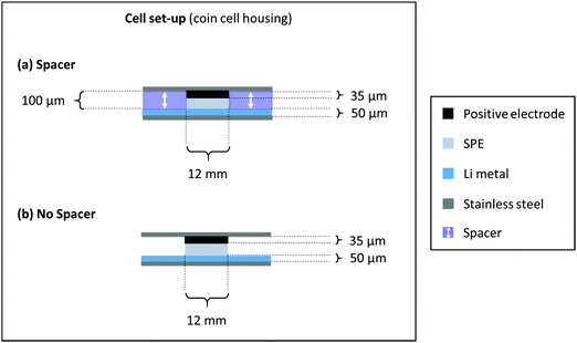 | ||
| Scheme 1 Cell assembly and respective dimensions of a cell build with (a) spacer and (b) without a spacer. | ||
(d) Electrochemical measurements
All constant current cycling experiments were conducted on a Maccor Series 4000 battery cell test system at 60 °C or 40 °C in a climate chamber (Binder KB400). The used C-rates and corresponding specific currents are mentioned within the text and/or in the figure captions.(e) Mechanical measurements
The compression behavior of the prepared SPE membranes was investigated using an Instron 5965 dual column universal testing machine (Instron, USA) with 50 mm compression plates. The samples were prepared by punching 18 mm discs of the SPE membranes with a thickness of approximately 2 mm. The measurements were performed with a speed of 20 μm min−1 at 40 and 60 °C.Results and discussion
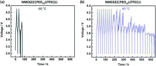
A typical scenario for PEO-based SPEs in NMC622|SPE|Li cells during charge/discharge cycling is depicted in Fig. 1. An irreproducible, time-, current- and voltage independent cell-failure appears already in the initial cycles at 60 °C (Fig. 1a).38 This noisy voltage response can be attributed to short circuits and can be seen for example in the 3rd cycle, where the voltage even decreases below 3 V despite the charging process.38 Interestingly, application at 40 °C (Fig. 1b) tends to postpone the onset of this failure and demonstrate milder progression after the onset.Penetration of Li dendrites to the opposite electrode is more likely when the distance between the electrodes is shorter.38 Given mechanical susceptibility to external pressure, the SPE can shrink and indeed decrease the electrode distance. The relation of the different failure onsets at different temperatures (Fig. 1) with the proposed SPE shrinkage was investigated by means of compression tests at 40 and 60 °C. The resulting curves of the compression tests are depicted in Fig. 2(a). At both temperatures, the SPEs are elastic up to a compressive strain of ≈1%. However, more compressive stress is required at 40 °C compared to 60 °C, which is 1.2 and 0.2 MPa, respectively.41 Hence, at a given pressure within a coin cell, less compression (shrinkage) of the PEO-based SPE at 40 °C can be concluded, also indicated by less “thinning/squeezing” of the SPE after 24 h storage in a coin cell, as visualized in Fig. 2(b). Consequently, the SPE can more resist pressure at 40 °C compared to 60 °C, and thus, can better retain its distance when sandwiched between the electrodes (Fig. 2b).
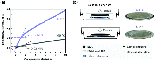 | ||
| Fig. 2 (a) Curves of compressive stress as a function of compressive strain for the PEO-based SPE at 60 and 40 °C. The limit of elastic compression (linear relation) is marked. For a similar compression (≈1% compressive strain), more force is necessary at 40 °C compared to 60 °C (0.12 vs. 0.02 MPa, respectively). (b) Hence, the PEO-based SPE within a coin cell is less prone to compression at 40 °C, and thus can retain higher distances between the electrodes than at 60 °C. This can be visually confirmed after disassembling the cells after 24 h of storage, where the SPE undergoes less thinning/squeezing at 40 °C. Higher electrode distances render short circuits less likely and may be related to the postponed onset of short circuits in NMC622||Li cells (Fig. 1). | ||
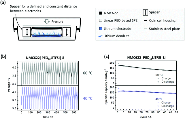
Obviously, susceptibility towards SPE compression and shrinkage renders voltage noise, and thus short circuits more likely. Additionally, the accompanying changes in thickness during operation make a systematic assessment of SPEs difficult. Thus, proper modification of the cell design is necessary, i.e. by use of a conventional spacer as shown in Fig. 3(a). The spacer can maintain a defined distance and significantly better prevent and/or postpone penetration of Li dendrites. This cell set-up as a reasonable performance reference can contribute to a more systematic assessment of SPEs (Fig. 3c). Even at 40 °C, high specific capacities (>150 mA h g−1) with good capacity retention are obtained. A reasonable benchmark system is essential for systematic and valuable R&D,45 and can be realized this way.
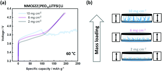
The less mechanical stability of the linear PEO-based SPE implies susceptibility to both shrinkage in thickness and Li dendrite penetration.41 However, a spacer can only counteract shrinkage. To address dendrite penetration, the cells are charged with varying (active) mass loadings of NMC622, which is depicted in Fig. 4(a). A higher mass loading of NMC622 implies a higher total charge current. As a consequence, higher current densities lead to higher overpotentials and Li dendrite growth.46–49 The spacer cannot avoid voltage noise failure at high mass loadings, as schematically illustrated in Fig. 4(b). The linear PEO-based SPE is mechanically not able to suppress dendrite penetration when the amount of dendritic Li deposition is high. Such intrinsic issue limits applicability to lower mass loadings. It is worth noting that the observed overpotential can also be impacted by insufficient wetting of NMC622 by the SPE, hinting at an additional limit of application of high mass loadings. It is also worth noting that analysis of overvoltage can be complex,50 as high surface area lithium (HSAL) e.g. dendrites can additionally affect overvoltage.
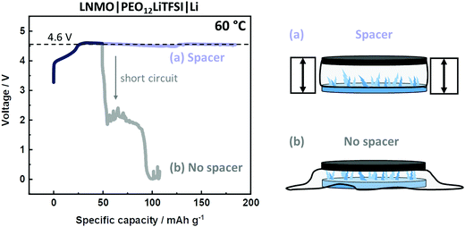
Finally, this modified cell setup can also improve the quality of other methods and techniques, e.g., determination of the electrochemical stability window (ESW). Given the arbitrary appearance of short circuits and voltage noise, the number of experiments needs to be enhanced in order to obtain a distinct anodic decomposition plateau on e.g., LiNi0.5Mn1.5O2 (LNMO) electrodes. A “successful” experiment is shown in Fig. 5, where the plateau at 4.6 V vs. Li|Li+ is obtained, before the appearance of a short circuit. However, a more effective and reproducible strategy can be obtained via the incorporation of a spacer. As shown in Fig. 5, this setup reveals a similar anodic plateau, but without the risk of short circuits, thus offering a significantly more efficient and effective way for R&D. Also, the spacer can realize measures and techniques where a defined thickness of the SPE is essential, e.g. measurement of Li+ transport properties.51,52
Conclusion
Noisy voltage responses as an indication for short circuit failure are typically observed for poly(ethylene oxide)-based solid polymer electrolytes (PEO-based SPEs) in Li metal batteries (LMBs) with high voltage/high energy electrodes e.g., LiNi0.6Mn0.2Co0.2O2 (NMC622).It is demonstrated that this failure onset happens earlier during cycling at higher temperatures. By compression tests, this can be related to mechanical differences. It is shown that the PEO-based SPE is mechanically more prone to shrinkage at 60 °C compared to 40 °C. In an assembled cell this results in SPE membrane thinning/squeezing and a more pronounced decrease in electrode distance, which is concluded to render short circuits via e.g., Li dendrite penetration more likely.
Incorporating a spacer as a proper modification of the cell setup can retain a defined distance between the electrodes and enables a reasonable charge/discharge cycling performance without short circuits for moderate mass loadings at 60 and 40 °C and finally realizes a practical benchmark cell system of a PEO-based SPE for systematic assessment of SPEs in high voltage LMBs.
Conflicts of interest
There are no conflicts to declare.Acknowledgements
Financial support from the German Federal Ministry for Education and Research within the project FestBatt (grant number: 13XP0175A) is gratefully acknowledged.References
- H. S. Shin, W. G. Ryu, M. S. Park, K. N. Jung, H. Kim and J. W. Lee, ChemSusChem, 2018, 11, 3184–3190 CrossRef CAS PubMed.
- G. Homann, P. Meister, L. Stolz, J. P. Brinkmann, J. Kulisch, T. Adermann, M. Winter and J. Kasnatscheew, ACS Appl. Energy Mater., 2020, 3, 3162–3168 CrossRef CAS.
- J. Kasnatscheew, R. Wagner, M. Winter and I. Cekic-Laskovic, Top. Curr. Chem., 2018, 376, 16 CrossRef PubMed.
- T. Placke, R. Kloepsch, S. Dühnen and M. Winter, J. Solid State Electrochem., 2017, 21, 1939–1964 CrossRef CAS.
- R. Schmuch, R. Wagner, G. Hörpel, T. Placke and M. Winter, Nat. Energy, 2018, 3, 267–278 CrossRef CAS.
- J. Kasnatscheew, T. Placke, B. Streipert, S. Rothermel, R. Wagner, P. Meister, I. C. Laskovic and M. Winter, J. Electrochem. Soc., 2017, 164, A2479–A2486 CrossRef CAS.
- J. Schnell, T. Gunther, T. Knoche, C. Vieider, L. Kohler, A. Just, M. Keller, S. Passerini and G. Reinhart, J. Power Sources, 2018, 382, 160–175 CrossRef CAS.
- L. Xu, S. Tang, Y. Cheng, K. Wang, J. Liang, C. Liu, Y.-C. Cao, F. Wei and L. Mai, Joule, 2018, 2, 1991–2015 CrossRef CAS.
- J. M. Tarascon and M. Armand, Nature, 2001, 414, 359–367 CrossRef CAS PubMed.
- F. B. Dias, L. Plomp and J. B. J. Veldhuis, J. Power Sources, 2000, 88, 169–191 CrossRef CAS.
- M. Winter, B. Barnett and K. Xu, Chem. Rev., 2018, 118, 11433–11456 CrossRef CAS PubMed.
- A. Sakuda, K. Kuratani, M. Yamamoto, M. Takahashi, T. Takeuchi and H. Kobayashi, J. Electrochem. Soc., 2017, 164, A2474–A2478 CrossRef CAS.
- F. Hao, F. D. Han, Y. L. Liang, C. S. Wang and Y. Yao, MRS Bull., 2018, 43, 775–781 CrossRef CAS.
- P. Janssen, J. Kasnatscheew, B. Streipert, C. Wendt, P. Murmann, M. Ponomarenko, O. Stubbmann-Kazakova, G.-V. Röschenthaler, M. Winter and I. Cekic-Laskovic, J. Electrochem. Soc., 2018, 165, A3525–A3530 CrossRef CAS.
- J. R. Nair, L. Imholt, G. Brunklaus and M. Winter, Electrochem. Soc. Interface, 2019, 28, 55–61 CrossRef CAS.
- C. Wang, T. Wang, L. Wang, Z. Hu, Z. Cui, J. Li, S. Dong, X. Zhou and G. Cui, Adv. Sci., 2019, 6, 1901036 CrossRef CAS PubMed.
- Z. G. Xue, D. He and X. L. Xie, J. Mater. Chem. A, 2015, 3, 19218–19253 RSC.
- L. Porcarelli, C. Gerbaldi, F. Bella and J. R. Nair, Sci. Rep., 2016, 6, 19892 CrossRef CAS PubMed.
- J. Wu, Z. Rao, Z. Cheng, L. Yuan, Z. Li and Y. Huang, Adv. Energy Mater., 2019, 9, 1902767 CrossRef CAS.
- J. Mindemark, M. J. Lacey, T. Bowden and D. Brandell, Prog. Polym. Sci., 2018, 81, 114–143 CrossRef CAS.
- J. Janek and W. G. Zeier, Nat. Energy, 2016, 1, 16141 CrossRef.
- S. P. Culver, R. Koerver, T. Krauskopf and W. G. Zeier, Chem. Mater., 2018, 30, 4179–4192 CrossRef CAS.
- W. B. Zhang, D. A. Weber, H. Weigand, T. Arlt, I. Manke, D. Schroder, R. Koerver, T. Leichtweiss, P. Hartmann, W. G. Zeier and J. Janek, ACS Appl. Mater. Interfaces, 2017, 9, 17835–17845 CrossRef CAS PubMed.
- K. Xu, Chem. Rev., 2004, 104, 4303–4417 CrossRef CAS PubMed.
- W. A. Henderson, Macromolecules, 2007, 40, 4963–4971 CrossRef CAS.
- A. Gupta, E. Kazyak, N. Craig, J. Christensen, N. P. Dasgupta and J. Sakamoto, J. Electrochem. Soc., 2018, 165, A2801–A2806 CrossRef CAS.
- G. B. Appetecchi, J. Hassoun, B. Scrosati, F. Croce, F. Cassel and M. Salomon, J. Power Sources, 2003, 124, 246–253 CrossRef CAS.
- J. Kasnatscheew, S. Röser, M. Börner and M. Winter, ACS Appl. Energy Mater., 2019, 2, 7733–7737 CrossRef CAS.
- J. Kasnatscheew, M. Evertz, B. Streipert, R. Wagner, S. Nowak, I. Cekic Laskovic and M. Winter, J. Power Sources, 2017, 359, 458–467 CrossRef CAS.
- J. Kasnatscheew, M. Evertz, R. Kloepsch, B. Streipert, R. Wagner, I. Cekic Laskovic and M. Winter, Energy Technol., 2017, 5, 1670–1679 CrossRef CAS.
- J. Kasnatscheew, M. Evertz, B. Streipert, R. Wagner, R. Klopsch, B. Vortmann, H. Hahn, S. Nowak, M. Amereller, A. C. Gentschev, P. Lamp and M. Winter, Phys. Chem. Chem. Phys., 2016, 18, 3956–3965 RSC.
- A. Manthiram, J. Choi and W. Choi, Solid State Ionics, 2006, 177, 2629–2634 CrossRef CAS.
- W. Li, B. Song and A. Manthiram, Chem. Soc. Rev., 2017, 46, 3006–3059 RSC.
- P. He, H. J. Yu, D. Li and H. S. Zhou, J. Mater. Chem., 2012, 22, 3680–3695 RSC.
- M. S. Whittingham, Chem. Rev., 2004, 104, 4271–4301 CrossRef CAS PubMed.
- W. Liu, P. Oh, X. Liu, M. J. Lee, W. Cho, S. Chae, Y. Kim and J. Cho, Angew. Chem., Int. Ed., 2015, 54, 4440–4457 CrossRef CAS PubMed.
- M. Hu, X. L. Pang and Z. Zhou, J. Power Sources, 2013, 237, 229–242 CrossRef CAS.
- G. Homann, L. Stolz, J. Nair, I. C. Laskovic, M. Winter and J. Kasnatscheew, Sci. Rep., 2020, 10, 4390 CrossRef PubMed.
- J. Kasnatscheew, B. Streipert, S. Röser, R. Wagner, I. Cekic Laskovic and M. Winter, Phys. Chem. Chem. Phys., 2017, 19, 16078–16086 RSC.
- G. Homann, L. Stolz, K. Neuhaus, M. Winter and J. Kasnatscheew, Adv. Funct. Mater., 2020, 30, 2006289 CrossRef CAS.
- G. Homann, L. Stolz, M. Winter and J. Kasnatscheew, iScience, 2020, 23, 101225 CrossRef CAS PubMed.
- B. Streipert, L. Stolz, G. Homann, P. Janßen, I. Cekic-Laskovic, M. Winter and J. Kasnatscheew, ChemSusChem, 2020, 13, 5301–5307 CrossRef CAS PubMed.
- R. Nölle, K. Beltrop, F. Holtstiege, J. Kasnatscheew, T. Placke and M. Winter, Mater. Today, 2020, 32, 131–146 CrossRef.
- L. Stolz, G. Homann, M. Winter and J. Kasnatscheew, ChemSusChem, 2021 DOI:10.1002/cssc.202100213.
- S. Klein, K. Borzutzki, P. Schneider, O. Fromm, J. Reiter, Q. Fan, T. Placke, M. Winter and J. Kasnatscheew, Chem. Mater., 2020, 32, 6279–6284 CrossRef CAS.
- H. Duan, Y.-X. Yin, Y. Shi, P.-F. Wang, X.-D. Zhang, C.-P. Yang, J.-L. Shi, R. Wen, Y.-G. Guo and L.-J. Wan, J. Am. Chem. Soc., 2018, 140, 82–85 CrossRef CAS PubMed.
- C. Brissot, M. Rosso, J. N. Chazalviel and S. Lascaud, J. Power Sources, 1999, 81, 925–929 CrossRef.
- J.-Y. Liang, X.-X. Zeng, X.-D. Zhang, T.-T. Zuo, M. Yan, Y.-X. Yin, J.-L. Shi, X.-W. Wu, Y.-G. Guo and L.-J. Wan, J. Am. Chem. Soc., 2019, 141, 9165–9169 CrossRef PubMed.
- C. Monroe and J. Newman, J. Electrochem. Soc., 2005, 152, A396–A404 CrossRef CAS.
- J. Kasnatscheew, U. Rodehorst, B. Streipert, S. Wiemers-Meyer, R. Jakelski, R. Wagner, I. C. Laskovic and M. Winter, J. Electrochem. Soc., 2016, 163, A2943–A2950 CrossRef CAS.
- L. Stolz, G. Homann, M. Winter and J. Kasnatscheew, Mater. Today, 2021 DOI:10.1016/j.mattod.2020.11.025.
- L. Stolz, G. Homann, M. Winter and J. Kasnatscheew, Data Briefs, 2021, 34, 106688 CrossRef PubMed.
| This journal is © The Royal Society of Chemistry 2021 |

