 Open Access Article
Conquering the crystallinity conundrum: efforts to increase quality of covalent organic frameworks
Laurens
Bourda
 ab,
Chidharth
Krishnaraj
 b,
Pascal
Van Der Voort
 *b and
Kristof
Van Hecke
 *a
*a
aXStruct, Department of Chemistry, Ghent University, Krijgslaan 281, Building S3, 9000 Ghent, Belgium. E-mail: kristof.vanhecke@ugent.be
bCOMOC, Center for Ordered Materials, Organometallics & Catalysis, Department of Chemistry, Ghent University, Krijgslaan 281, Building S3, 9000 Ghent, Belgium. E-mail: pascal.vandervoort@ugent.be
First published on 29th March 2021
Abstract
Due to their high designability, covalent organic frameworks (COFs) are attractive candidates in many different applications. However, COF synthesis is still poorly understood and mainly trial and error based. In this review, we pave the way to a better understanding of COF chemistry and the synthesis of high-quality COFs. To achieve this goal, the main challenge in COF synthesis, the crystallization problem, is explained. Additionally, mechanisms for boroxine and imine COF formation are proposed. Afterwards, several approaches to increase COF quality are discussed: addition of modulators, slowing down monomer addition, improvement of used catalysts, study of solubility effects and interfacial synthesis, application of exchange reactions and finally linker specific observations. The discussed techniques can be seen as a toolbox usable for the synthesis of high-quality COFs.
1 Introduction
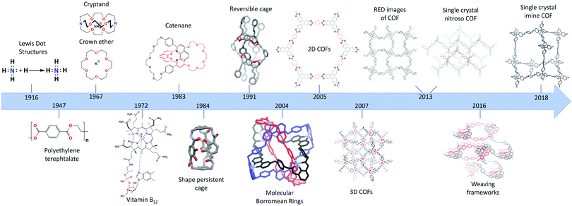
The recent discovery of covalent organic frameworks (COFs) in 20051 can be acknowledged as the “pièce de resistance” of almost a century of increasing control over the dynamic bond. In 1916, Lewis published “The atom and the molecule”,2 a crucial paper visualizing the bonding of atoms in molecules through the concept of covalent bond. Today, just over 100 years later, chemists are able to grow single crystals of extended 3D structures.3 To reach this stage, several important milestones had to be crossed,4 of which the most important ones are presented in Fig. 1.Staudinger's “Über Polymerisation”,5,6 established in 1920, can be regarded as the start of polymer science. Thereon, a new field studying these 1D macromolecules emerged, resulting in Staudinger being awarded the 1953 Nobel Prize in Chemistry. Meanwhile, with the first total synthesis (urea) already reported in 18287 and the synthesis of mauveine8 and aspirin9 having revolutionized the dye and pharmaceutical industries, organic synthesis was becoming an ever growing field.10 In the second half of the 20th century, a high level of synthetic control had already been established, illustrated by the achievements of Robert Burns Woodward11 (Nobel Prize in Chemistry, 1965) who synthesized a whole array of compounds including quinine, respirine, chlorophyll and the famous vitamin B1212 (1972, with Eschenmoser) which was the most complex natural occurring product synthesized in the lab at that time.
Thus, by the end of the 20th century organic synthesis had evolved to a mature science and (1D) macromolecules had been developed to a great extent and found industrial applications. But still, no extended organic 2D nor 3D structures were reported, a blind spot aptly illustrated by Roald Hoffmann in 1993 “Organic chemists are masterful at exercising control in zero dimensions. One subculture of organic chemists has learned to exercise control in one dimension. But in two or three dimensions, it's a synthetic wasteland. The methodology for exercising control so that one can make unstable but persistent extended structures on demand is nearly absent”.13 Still, since the 1960's, great process had already been made in a field called “supramolecular chemistry”, where quite sophisticated architectures could be built. Important breakthroughs were the synthesis of crown ethers14 and cryptands,15 by Pedersen and Lehn, respectively. Additionally, the first permanent porous materials were created using supramolecular chemistry and reported as shape-persistent cages in 1984 by Vögle16 and Cram.17 Pedersen, Lehn and Cram received the Nobel prize in Chemistry 1987 for their developments in supramolecular chemistry. This field is based on non-covalent interactions, which allows high reversibility and thermodynamic control with error-correction and self-assembly as highly attractive features. However, due to the associated weak, non-covalent bonds, modification of these structures proved difficult, as losses of structural integrity and alterations of the binding interactions are often observed as a consequence of functionalization. Therefore, one needed to be able to control the formation and error-correction of the stronger covalent bonds, which was realized with dynamic covalent chemistry (DCC) and its kinetic reaction control.18 The field of mechanically interlocking molecules, with the first catenane, consisting of two interlocking rings, synthesized in 1983 by Sauvage19 was crucial for the development of DCC. As no dynamic chemistry was used here, the yield was only 72%, which would be disastrous for complicated structures containing far more rings. Since then, many different catenanes have been developed based on reversible covalent reactions with a large contribution from Sir. James F. Stoddart. His molecular borromean rings (2004) are an elegant example of the possibilities of this type of chemistry, as he could obtain three mechanically interlocking rings with a 100% yield.20 In 2016 Sauvage and Stoddart received the Nobel prize in Chemistry (together with Feringa) for their contributions in DCC and molecular machines. DCC was also used to create shape-persistent cages in high yields,21 allowing the creation of a large variety of sizes and shapes of permanently porous cages.22
In 2005 (2D)1 and 2007 (3D)23 extended crystalline COFs could be synthesized using these reversible covalent linkages. As these frameworks are completely composed of strong covalent bonds they are expected to be highly stable and can be easily modified. However, some exceptions still exist, as will be discussed in Section 1.1.1. Furthermore, the combination of their intrinsic porosity and chemical robustness makes it possible to obtain materials with high permanent porosities. Over the years, the achievable crystallinity of COFs improved rapidly, which led to two major breakthroughs in 2013 when single crystal structures of COFs could be solved. Yaghi et al. succeeded in the synthesis of COF-320 with crystals up to 200 nm which could be solved using Rotation Electron Diffraction (RED)24 and Wuest et al. obtained crystals of nitroso polymer networks suitable for Single Crystal X-ray Diffraction (SXRD) analysis.25 An interesting subset are the class of woven COFs (wCOFs), firstly reported by the Yaghi group in 2016.26 These materials are made through the molecular weaving of distinct threads. While the removable “crossings” of those threads are composed of metal-coordination bonds, the threads are completely composed of strong covalent bonds, making these materials essentially COFs. Moreover, the single crystal structures of these materials could be solved using 3D-Electron Diffraction Tomography (3D-EDT). Finally, in 2018, ultimate control was reached, with the synthesis of 3D COF crystals of up to 60 μm, linked by strong imine bonds.3
1.1 Design of COFs
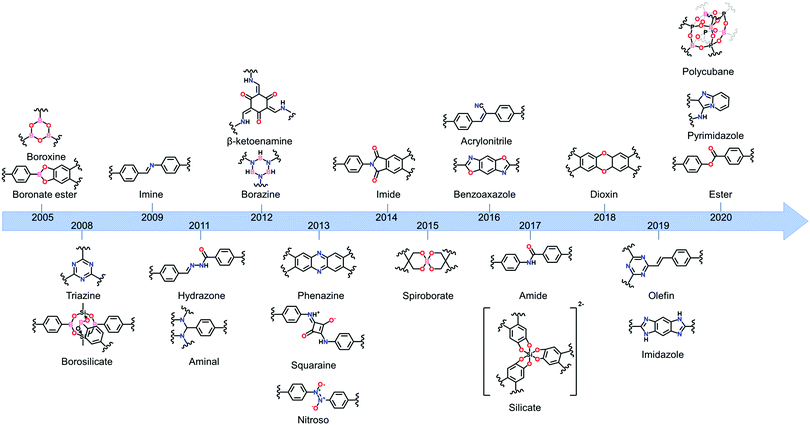
One of the main advantages of COFs is their high designability. By carefully choosing functional groups and symmetry of the used building blocks, COFs with specific functionalities and framework structures can be obtained.27 In theory, linkers only require a rigid backbone allowing directional bonding and reactive end-groups able to trigger dynamic covalent reactions for making highly crystalline COFs. However, in practice this is not that convenient.![[double bond, length as m-dash]](https://www.rsc.org/images/entities/char_e001.gif) N– linkage, which gives rise to extremely stable materials.31 However, even with harsh synthetic conditions (400 °C, molten ZnCl2), the obtained crystallinity can be referred to as moderate at best. Since the first report of COF-300 in 2009,32 the Schiff base imine linkage and its derivatives have arguably become the most extensively studied linkers in COF chemistry. This can be partially attributed to the high availability and affordability of a large variety of aldehyde and amine precursors along with the increased linkage stability in humid environments and neutral to basic pH.33 Moreover, the employed Schiff base reactions are well studied and can easily be controlled by the addition of acid catalysts. Over the next years, Schiff base chemistry has also been used to make different related linkages like hydrazone,34 β-ketoenamine,35 phenazine,36 squaraine37 and benzoxazole38 COFs. Particularly the β-ketoenamine linkage is interesting as it combines a highly reversible, imine condensation with a subsequent irreversible tautomerization to a highly stable β-ketoenamine COF. C–N bonds could also be used for COF formation, as shown by the aminal COF,39,40 which is stable in both acid and base. The borazine linkage, isostructural to the boroxine and triazine linkages, was reported in 201241 and the previously mentioned weak nitroso linkage in 2013.25 The following year, 2014, the first report of imide COFs appeared,42 for which the synthesis could be made reversible by carefully adjusting the basic catalyst and reaction conditions.29 The spiroborate linkage,43 reported in 2015, provided a more stable B–O type linkage which is intrinsically anionic, with exchangeable counterions. However, while stable in aqueous and mild basic environments, the material was still susceptible to acidic conditions. In 2016, another major hurdle was overcome, by the synthesis of the fully conjugated acrylonitrile COF 2DPPV,44 based on C
N– linkage, which gives rise to extremely stable materials.31 However, even with harsh synthetic conditions (400 °C, molten ZnCl2), the obtained crystallinity can be referred to as moderate at best. Since the first report of COF-300 in 2009,32 the Schiff base imine linkage and its derivatives have arguably become the most extensively studied linkers in COF chemistry. This can be partially attributed to the high availability and affordability of a large variety of aldehyde and amine precursors along with the increased linkage stability in humid environments and neutral to basic pH.33 Moreover, the employed Schiff base reactions are well studied and can easily be controlled by the addition of acid catalysts. Over the next years, Schiff base chemistry has also been used to make different related linkages like hydrazone,34 β-ketoenamine,35 phenazine,36 squaraine37 and benzoxazole38 COFs. Particularly the β-ketoenamine linkage is interesting as it combines a highly reversible, imine condensation with a subsequent irreversible tautomerization to a highly stable β-ketoenamine COF. C–N bonds could also be used for COF formation, as shown by the aminal COF,39,40 which is stable in both acid and base. The borazine linkage, isostructural to the boroxine and triazine linkages, was reported in 201241 and the previously mentioned weak nitroso linkage in 2013.25 The following year, 2014, the first report of imide COFs appeared,42 for which the synthesis could be made reversible by carefully adjusting the basic catalyst and reaction conditions.29 The spiroborate linkage,43 reported in 2015, provided a more stable B–O type linkage which is intrinsically anionic, with exchangeable counterions. However, while stable in aqueous and mild basic environments, the material was still susceptible to acidic conditions. In 2016, another major hurdle was overcome, by the synthesis of the fully conjugated acrylonitrile COF 2DPPV,44 based on C![[double bond, length as m-dash]](https://www.rsc.org/images/entities/char_e001.gif) C linkages, which was reported to be stable in various solvents and concentrated acids and bases.45 Due to the strong electron withdrawing cyano groups, the formation of this strong bond could be made reversible. Two new linkages were reported in 2017, the anionic silicate linkage,46 which showed the potential of the use of Si atoms in the synthesis of COFs but was unstable in aqueous environments and the highly stable amide linkage47 which could be made reversible at high temperatures (>200 °C). While the amide linkage was already reported in 2016 via chemical conversion of imine linkages,48 this was the first report of direct formation of amide bonds as COF linkage. It was observed that the materials were highly stable in both acid and base, outperforming even the most stable imine COFs and amide COFs formed via post-modification. The dioxin linked COFs49 COF-316 and COF-318 were, in 2018, the first COFs to be formed through an aromatic substitution reaction. Although the ring closing step could not be made reversible, crystalline COF formation was possible under highly specific conditions (by addition of nitrile side groups). The strong dioxin bonds formed resulted in high stability of the material in concentrated base or acid. Subsequently, COF-701, the first unsubstituted olefin linked COF was reported in 2019 and could be formed via an aldol condensation reaction.50,51 Stability tests showed the material withstanding both aqueous and organic solutions of strong base and acid. In the same year, an imidazole linked COF, chemically comparable to the previously mentioned benzoaxazole linkage, could be obtained by reaction of carboxylic acids and diamines.52 Finally, very recently the ester,53 pyrimidazole54 and polycubane55 linkages were added to the ever expanding library of COF linkages. Whereas the pyrimidazole linkage was shown to be stable in both 9 M HCl and NaOH, the ester linkage was susceptible to both acids and bases but stable in aqueous environments. While more linkages have been claimed to be used in the synthesis of COFs, we choose to stick to the original definition of discoverer Omar M. Yaghi, saying that COFs should be permanently porous and crystalline,56 to create this list. Additionally, some linkages which only differ in functional group substitution like azine,57 indoimine58 and urea59 for imine, heptazine60 for triazine and Michael addition–elemination61 for β-ketoenamine are not discussed.
C linkages, which was reported to be stable in various solvents and concentrated acids and bases.45 Due to the strong electron withdrawing cyano groups, the formation of this strong bond could be made reversible. Two new linkages were reported in 2017, the anionic silicate linkage,46 which showed the potential of the use of Si atoms in the synthesis of COFs but was unstable in aqueous environments and the highly stable amide linkage47 which could be made reversible at high temperatures (>200 °C). While the amide linkage was already reported in 2016 via chemical conversion of imine linkages,48 this was the first report of direct formation of amide bonds as COF linkage. It was observed that the materials were highly stable in both acid and base, outperforming even the most stable imine COFs and amide COFs formed via post-modification. The dioxin linked COFs49 COF-316 and COF-318 were, in 2018, the first COFs to be formed through an aromatic substitution reaction. Although the ring closing step could not be made reversible, crystalline COF formation was possible under highly specific conditions (by addition of nitrile side groups). The strong dioxin bonds formed resulted in high stability of the material in concentrated base or acid. Subsequently, COF-701, the first unsubstituted olefin linked COF was reported in 2019 and could be formed via an aldol condensation reaction.50,51 Stability tests showed the material withstanding both aqueous and organic solutions of strong base and acid. In the same year, an imidazole linked COF, chemically comparable to the previously mentioned benzoaxazole linkage, could be obtained by reaction of carboxylic acids and diamines.52 Finally, very recently the ester,53 pyrimidazole54 and polycubane55 linkages were added to the ever expanding library of COF linkages. Whereas the pyrimidazole linkage was shown to be stable in both 9 M HCl and NaOH, the ester linkage was susceptible to both acids and bases but stable in aqueous environments. While more linkages have been claimed to be used in the synthesis of COFs, we choose to stick to the original definition of discoverer Omar M. Yaghi, saying that COFs should be permanently porous and crystalline,56 to create this list. Additionally, some linkages which only differ in functional group substitution like azine,57 indoimine58 and urea59 for imine, heptazine60 for triazine and Michael addition–elemination61 for β-ketoenamine are not discussed.
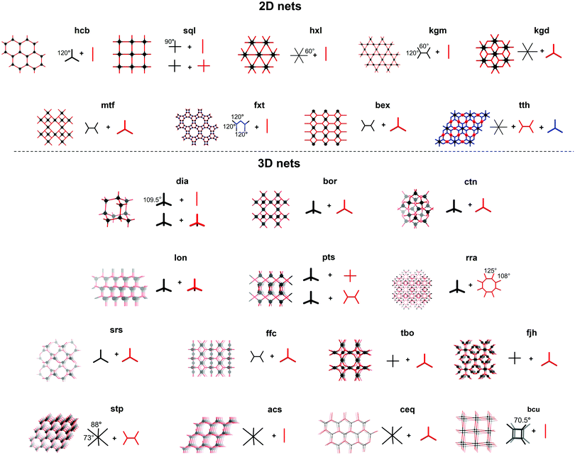
These nets can be described as a collection of nodes and edges, with the difference between edge and node determined by the number of connections made. Edges can make exactly two connections, as e.g. the terephtaldehyde (BDA) linker in COF-300 (Fig. 3A and B). COF nodes can be defined as linkers making three or more connections, in our COF-300 example, tetrakis(4-aminophenyl)methane (TAM) is the node. COF-300 only has one kind of node (uninodal) and one kind of edge (edge-transitive),65 later on examples with multiple edges or nodes will be shown. Additionally to the number of connections, the local symmetry is important too, for example a tetratopic node (four connections) can be described as a tetrahedron (as in COF-300), square plane or reduced symmetry square plane (all three possibilities are drawn in Fig. 4). Finally, the connections between edges and nodes and the respective spatial arrangement co-define the formed net.66 This indicates that multiple nets can be formed by one edge/node combination, resulting in a vast amount of possible nets (2927 3D nets and 200 2D nets could be found in the Reticular Chemistry Structure Resource, RCSR).64 However, only very few make up for the vast majority of reported structures.67
Until now, 23 nets have been reported for COFs divided in nine 2D layered structures and 14 3D nets. The formed nets as well as some edge/node combinations used to obtain these are presented in Fig. 4. As most linkers are largely constructed from aromatic rings and sp2-hybridized atoms for reasons of rigidity, strong π–π interactions make the crystallization of 2D layered structures favorable.65 Among the 2D layered structures, the lion's share of COFs crystallize in one of the five edge-transitive nets. Of those, four nets are uninodal and only the kgd net is binodal, as it combines a hexatopic and a tritopic node.68 The uninodal 2D nets are the hexagonal hcb net,1 the sql net constructed from square tetratopic linking units,69 the hxl net with triangular pores70 and the kgm net,71 which is obtained by the linking of tetratopic building units with reduced symmetry (respectively 120° and 60° between the points of extension instead of 90°) like 4,4′,4′′,4′′′-(ethene-1,1,2,2-tetrayl)-tetraaniline (ETTA). Lately, efforts have been made to increase the structural diversity of 2D COFs, resulting in the reports of COFs based on the mtf,72fxt,73bex74–76 and tth77 non-edge-transitive 2D nets. At this point it is important to note that the relationship between node geometry and topology of the resulting COF is not as straightforward as it seems. Not only can the same net be formed by different node combinations (for example a sql net can be formed by the condensation of a tetratopic node with an edge, or two tetratopic nodes), also some combinations can in theory lead to different nets (the combination of a desymmetrized tetratopic linker with a tritopic linker has for example already been reported to crystallize in mtf and bex topologies). It is not always possible to predict what topology will be formed, although a general rule of thumb exists: “the materials have a tendency to crystallize in the symmetrical topology possible and will form 2D layered structures whenever possible.”78
Theoretically, structural diversity is much larger for 3D than 2D structures. However, until now, only 14 nets have been reported in the synthesis of 3D COFs, which can be explained by the increased difficulty in crystallizing these compounds in combination with the reduced stability and need for polyhedral linkers.79 Almost half of these nets are constructed using a tetrahedral node, with the dia topology being by far the most common.32 These networks are obtained by reticulation of a tetrahedral node with a linear linker or another tetrahedral node. However the latter combination can also result in a material with lon topology.3 Combination of these tetrahedral nodes with a tritopic linker can give both ctn or bor networks, where the main difference is the topological density (number of vertices per unit volume) of the networks.23 The pts net could be obtained by the reaction of C4 linkers with tetrahedral nodes,80 while the rra topology was accessed by combining a tetrahedral node with γ-cyclodextrin.81 It is important to note that these networks can also be formed through molecular weaving, as the structure-defining metal complex in a woven framework can essentially be seen as a tetrahedral node. This way, woven networks of dia and pts topology have already been prepared.26,82,83
From 2018, COFs crystallizing in 3D nets without the use of tetrahedral nodes where found, like the srs net built of two C3 linkers. However, the [SiO6]2− linker also coordinates two Na+ cations, making the linker chiral and non-coplanar.84 Combination of planar C4 and C3 nodes can lead to materials in different topologies, of which a rich library exists in the metal organic framework (MOF) world. However, only three 3D COF topologies (ffc,85tbo86 and fjh87) have been reported based on this combination of linkers. Recently, trigonal prismatic nodes have been used in 3D COF synthesis, resulting in nets with the stp,88acs89,90 and ceq90,91 topology. Finally, the bcu net could be obtained by using the aforementioned polycubane linkage as a octahedral node.55
The structural diversity of COFs goes beyond the underlying topologies, for example isoreticular expansion and contraction is an often studied concept which can have large implications on the structure. Some 3D structures (like dia and pts topologies) are prone to interpenetration, which can be significantly altered by expanding or contracting the used linkers.78,79 In 2D structures, stacking modes can have a huge influence on properties, varying from AA over AB to even ABC′ stacking modes.92,93 Moreover, layer stacking can be influenced by solvent adsorption94 or linker substituents.95 Additionally, linker desymmetrization can significantly alter the framework, without changing the underlying topology. Using this principle, COFs crystallizing in a hcb net with hierarchical96 or brick-wall97 pores could be obtained.
2 The crystallization problem
As already shortly discussed above, one of the main issues in the world of COFs is the crystallization problem, which essentially means that the more stable a solid compound is, the harder it is to crystallize (Fig. 5A). For example, compounds held together by weak interactions as van der Waals forces and hydrogen bonds, will crystallize relatively easily, while coordination networks are already more complicated to crystallize. However, it really gets problematic once you get into the domain of reticular chemistry.99 To obtain such extended crystalline solids, like MOFs and COFs, it is essential to have reversible linkage formation, on a time scale that allows for error-correction, whereas the formation of covalent bonds is generally already irreversible under very mild conditions.100 As a consequence, while MOF single crystals are still regularly reported, COF crystallization is still highly problematic. So, the trick is to make the formation of those highly stable linkages more reversible, as this will give more room for error-correction and thus make the crystalline product more accessible.78 Practically, this is done using the principles of DCC, as shown in Fig. 5B. In contrast to most synthetically used reactions, DCC allows a covalent bond to be broken and reformed, making error-correction possible. During reaction, products will gradually equilibrate from the kinetic (amorphous) product, rapidly formed due to the low activation barrier (ΔGi), to the thermodynamically stable (crystalline) product with the largest reduction in standard Gibbs free energy (ΔG0).98 This also makes it possible to control the reaction by introducing stabilizing features for the desired product and driving the reaction equilibrium by using excess starting materials, modulators or removing condensation products.18 As a consequence, a detailed understanding of the different reaction states in the formation of COFs will yield higher control over the crystallinity of the product. Still, it has to be noted that the polymerization and resulting precipitation of COFs is a complicating factor, as precipitated amorphous networks might get kinetically trapped. Especially 3D COF formation, fully constructed from covalent bonds, is hindered by this problem, whereas the π–π stacking interactions in 2D COFs help driving the reaction to a layered structure.101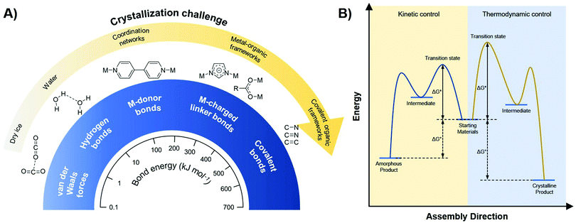 | ||
| Fig. 5 (A) Relationship between bond strength and crystallization challenge for different interactions. When going from weak (van der Waals forces, hydrogen bonds) over intermediate (metal-donor bonds) to strong (metal-charged linker bonds, covalent bonds) interactions, the crystallization challenge increases dramatically. (B) Free energy profile illustrating the difference between kinetic (green) and thermodynamic (red) control. When a reaction is kinetically controlled (like most covalent reactions), it is irreversible and amorphous products will be formed. Thermodynamically controlled reactions (like supramolecular chemistry and dynamic covalent chemistry) are reversible and can yield crystalline materials. Reproduced and adapted with permission from ref. 98. Copyright MDPI (2017). | ||
2.1 Mechanism of boroxine COF formation
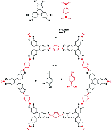
As the first COFs were based on boroxine and boronate ester chemistry, much research has been done on elucidating the formation mechanism of these materials. The underlying chemistry is quite straightforward, driven by Lewis acidic dimer formation between oxygen and boron atoms of two B(OH)2 moeities (with expulsion of a water molecule). This process repeats three times, until a B3O3 ring and three H2O molecules are formed.105 As the boron atoms retain their Lewis acidic character and can easily be attacked by oxygen in e.g. H2O, the reaction is completely reversible However, precipitation of oligomers and crystallites severely complicate the mechanism and analysis of boroxine COF formation, therefore requiring more in-depth research. A first mechanistic study bypassed this issue by adjusting the solvent combinations until fully homogeneous growth conditions could be obtained for COF-5 (by using 4/1 dioxane/mesitylene as solvent with 15 eq. methanol to the catechol as solvent), making it possible to track the COF formation via turbidity measurements.102 A reproducible induction period was observed, which is followed by gradual precipitation of the COF as evidenced by an initial linear increase of turbidity in the COF mixture. Moreover, as shown in Fig. 6A, the induction period and formation rate are readily influenced by temperature, with lower temperatures leading to longer induction periods and slower COF formation. The influence of modulation on the formation of COF-5 was also studied (Fig. 6B), it can be observed that as soon as a modulator is added, the COF formation slows down, indicating that competing reactions are indeed happening. However, as no modulator was incorporated in the final COF structure and the isolated yields with and without modulator were very comparable, it could be concluded that an irreversible step is present in the reaction mechanism. Afterwards, even addition of large amounts of modulator was not sufficient to decrease turbidity, indicating chemical inaccessibility of these crystallites. Finally, the effect of H2O addition was studied, which could theoretically inhibit COF formation via Le Châtelier's principle. Indeed, addition of 15 eq. H2O afforded larger crystallites as evidenced by the sharper (100) Powder X-Ray Diffraction (PXRD) peak at a 2θ value of 3.5° (Cu Kα radiation) shown in Fig. 6C. Nonetheless, a practical limit for this method of crystal growing exists, as adding 20 eq. of H2O resulted in little to no COF formation after several days. These results indicate that efficient control of temperature and H2O in the reaction, as well as modulator addition can vastly improve the synthesis of boroxine and boronate COFs. Later on, the same procedure was used to study the difference in the kinetics of COFs made by different linkers.103 Two different effects can be observed from Fig. 6D, namely an increase in formation rate when the aromatic domains of the linker increases and a decrease in formation rate with increasing pore size. The first, and most important effect was attributed to stabilization of the intermediate by layer stacking, while the second could be explained by the decrease in interlayer attraction. Thus, it could be concluded that the rate determining step in the formation of 2D COFs is the interlayer stacking, yielding strong interactions and faster precipitation. Theoretical studies on the formation of boronate ester COFs have also been done, tracking the crystallization of COF-5 via kinetic Monte Carlo simulations,106 free energy techniques107 and molecular dynamics simulations.108 Firstly, linkers stack and form oligomers, a process that needs heating. Subsequently, these oligomers can nucleate via two different mechanism, i.e. stacking of metastable layers and templated polymerization. It should be noted that all these steps are fully reversible and exchangeable (as shown in Fig. 6G). However, due to the strong stacking interactions between the linkers, these processes cause a tremendous amount of hard to anneal defects, which limit COF crystallinity. It has been shown that appropriate solvents can greatly reduce the amount of effective stacking interactions and therefore increase crystallinity.107 Moreover, addition of H2O and methanol can vastly increase reversibility of the boronate ester formation as these molecules stabilize the transition state from a highly strained 4-ring to a more stable 6-ring, therefore lowering the activation energy from 25 kcal mol−1 to 13 or 14 kcal mol−1, respectively. Hence for the growth of large COF crystals the irreversible agglomeration and subsequent precipitation of small crystallites are problematic (as can be noticed in the proposed model in Fig. 6G).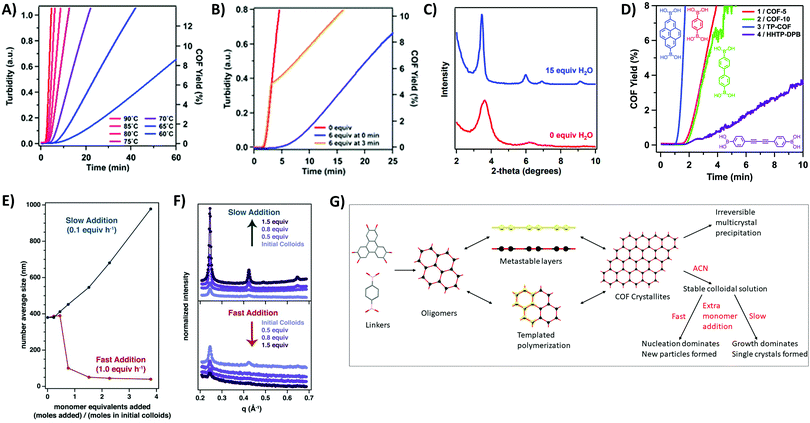 | ||
| Fig. 6 Mechanistic studies on COF-5. (A) Turbidity increase over time tracked at various temperatures. Highest temperature (90 °C) is indicated in red, lowest (60 °C) in blue. Turbidity is directly proportional to the rate of COF precipitation. (B) Influence of modulator (4-tert-butylcatechol) addition on COF synthesis, equivalents are taken relative to the amount of 2,3,6,7,10,11-hexahydroxytriphenylene (HTTP). Curve without modulator is shown in red, addition of 6 eq. of modulator at zero minutes is presented in blue and the orange curve shows addition of 6 eq. of modulator at three minutes. (C) Partial PXRD pattern for COF-5 synthesized with 0 (red) or 15 (blue) eq. of additionally added H2O. (D) COF Formation over time for four different boronate COFs (COF-5 in red, COF-10 in green, TP-COF in blue and HHTP-DPB in purple). All four COFs are built from the condensation of HTTP with the linker drawn next to the curve. (E) DLS average size of COF-5 particles as a function of the added monomer concentration. Slow addition (0.1 eq. per h) is shown in blue, fast addition (1.0 eq. per h) in red (F) WAXS patterns of COF-5 particles. The upper graph shows the influence of slow monomer addition, the lower graph the influence of fast monomer addition. (G) Proposed mechanism of formation for COF-5 using combined information from available mechanistic studies. Linkers react readily to oligomers, which can stack to metastable layers or go through templated polymerization processes. Eventually COF crystallites form, which precipitate immediately to chemically unavailable multicrystals if not stabilized by nitrile solvents as ACN. Stable colloidal COF solutions can be further reacted by the addition of new monomers. If these monomers are added in a rapid way, nucleation dominates and new (small) particles are formed, but if these additional monomers are added slowly, growth dominates and single crystals are formed. Reproduced with permission from: (A–C) ref. 102, Copyright American Chemical Society (2014); (D) ref. 103, Copyright Royal Society of Chemistry (2015); (E and F) ref. 104, Copyright American Association for the Advancement of Science (2018). | ||
A solution for this was reported in 2017, when the Dichtel group succeeded in stabilizing COF-5 colloids by the addition of small volume fractions of nitrile solvents (like acetonitrile, ACN).109 The obtained colloids were stable for over a month and were shown to be crystalline by Wide/Small-Angle X-ray Scattering (WAXS/SAXS) measurements. While the particle size was shown to be dependent on the amount of added nitrile solvent (with larger colloids forming at lower vol% due to aggregation of small crystallites), no change in particle size was observed when the solvent composition was altered after colloid formation. This indicated kinetic trapping of the COF in the formed colloids. Moreover, the reported procedure could be extended to a range of different linkers (DBD-COF, BPh-COF, Py-COF), 3D materials (COF-105, COF-108) and boroxine linked COFs (COF-1, COF-102, COF-103).110 In 2018, these kinetically trapped colloids were used for the synthesis of large single crystals of COF-5, COF-10 and TP-COF, by the slow addition of monomers.104 From Fig. 6E and F, it can be observed that when monomers were added to these stabilized colloids at a rate of 0.1 eq. per hour both crystallinity and particle size improved, as could be measured by Dynamic Light Scattering (DLS) and WAXS. However, when fast monomer addition was tested, particle size and crystallinity diminished, most likely because the critical nucleation concentration was reached. This indicates the importance of effective nucleation and growth separation for the synthesis of large COF crystals. Recent kinetic Monte Carlo simulations supported these results, as second order kinetics were obtained for nucleation while growth processes were calculated to be of a pseudo-first order in monomer concentration.111 However, crystal growth by keeping the monomer concentration below the critical value for crystal expansion is impractical, as a quadratic dependence on time was observed which corresponds to time ranges for the growth of millimeter sized crystals in the order of millions of years.
2.2 Mechanism of imine COF formation
Imine chemistry was, in contrast to boroxine chemistry, already much more studied before the first reports of COFs based on this type of linkages were reported. For example, these reactions were already widely used in DCC114 and Schiff base synthesis.115 Therefore, three reversible reactions happening simultaneously were already identified, namely imine condensation, exchange and metathesis (Fig. 7E). Interestingly, imine exchange was found to happen more rapidly than imine condensation,116 making amine modulators very interesting candidates to improve error-correction, as they provide extra functionalities capable of imine exchange. In 2015, a first mechanistic study of imine COFs was published by the Dichtel group.112 They concluded that both H2O and acetic acid are indispensable in the synthesis of the studied TAPB-BDA COF (TAPB: 1,3,5-tris(4-aminophenyl)benzene). From Fig. 7A, it is clear that no solids are obtained when COF synthesis is attempted without added acetic acid, while absence of H2O leads to amorphous powders. High yields and crystallinity could be obtained only when ≥3.3 M H2O and ≥1 M acetic acid were added, but increasing the concentrations above this threshold did not improve the quality of the obtained COF. Moreover, a two-step mechanism was observed, with rapid precipitation of an amorphous solid followed by dynamic imine exchange to finally obtain a crystalline material after a few days. As Fourier-transform infrared spectroscopy (FTIR) analysis of the formed amorphous solid did not show any amine or aldehyde peaks and the yield was already 95% after 15 minutes, it was concluded that no free monomers or oligomers were needed to achieve this amorphous to crystalline transformation. This theory was further supported by the possibility to grow crystalline COFs from isolated and cleaned amorphous solids.112 Additionally, it was proven possible to recrystallize an amorphous polyimine (coated around Fe3O4 nanoparticles) to a crystalline COF without changing the morphology or particle size.117 However, quite recently, an alternative pathway was proposed based on the observation of crystalline lattice fringes in Transmission Electron Microscopy (TEM) samples of COFs prepared in reaction times as short as 60 seconds. As the observed sheets were very thin, it was suggested that COFs might initially crystallize as disordered sheets, followed by a recrystallization to ordered and porous powder.118 Moreover, equilibration of these 60 seconds samples in supercritical CO2 (scCO2) for 72 hours led to crystalline peaks as observed by PXRD. The difference between both proposed mechanism is illustrated in Fig. 7F.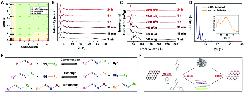 | ||
| Fig. 7 Mechanistic studies on imine COFs. (A) TAPB-BDA COF formation (4/1 dioxane/mesitylene, 70 °C, 3D, vacuum activation) as a function of H2O and acetic acid concentration. Shaded areas are added as a guide for the eye. (B) Normalized PXRD patterns of TAPB-BDA COF (4/1 dioxane/mesitylene, 70 °C, 33 vol% 10.5 M acetic acid, scCO2 activation) in function of time. (C) Normalized Pore Size Distributions and SBET values of TAPB-BDA COF (4/1 dioxane/mesitylene, 70 °C, 33 vol% 10.5 M acetic acid, scCO2 activation) in function of time. (D) PXRD pattern of TAPB-BDA COF (4/1 dioxane/mesitylene, 70 °C, 33 vol% 10.5 M acetic acid, 4 h) using vacuum (yellow) and scCO2 (blue) activation. (E) Overview of the chemical mechanism of imine COF formation, the three types of imine reactions: imine condensation, imine exchange and imine metathesis. (F) Schematic drawing of the physical mechanism of imine COF formation. When linkers are combined in presence of large excess of aniline single crystal COFs can form over months. Alternatively, amorphous polymers or disordered sheets are rapidly formed (within seconds) and subsequently slowly rearranged to COF multicrystals (hours). Reproduced with permission from: (A) ref. 112, Copyright Royal Society of Chemistry (2016); (B–D) from ref. 113, Copyright John Wiley and Sons (2019). | ||
Additionally, a significant influence of activation methods was observed, with crystalline COFs obtained (via in situ X-ray diffraction) at reaction times as short as 90 seconds while common synthetic conditions required three days of reaction time. This could be explained by pore collapse during vacuum drying of COFs. However, when activation was performed using scCO2, highly crystalline and porous imine COFs could be readily synthesized at short reaction times (four hours), as shown in Fig. 7B and C.113 The difference between scCO2 and vacuum activation for TAPB-BDA COF is illustrated in Fig. 7D. Still, not all imine COFs suffer from these pore collapse processes, with more robust materials taking advantage of alkoxy side-groups or enlarged π–π systems in the linkers.119 Furthermore, it was shown that framework damage for fragile materials was (partially) reversible by treatment with scCO2, while FTIR spectra were unaffected by the activation method, indicating that these effects could be attributed to physical processes.113,119 Recent Density-Functional Theory (DFT) calculations seemed to partially explain these observations, as it was observed that π–π layer interactions are not strong enough in solution leading to the coexistence of different stacking modes and thus disorder. Materials with large pores and small p-conjugated structures (fragile) were shown to be prone to random rearrangement. Finally, as quite expensive equipment is needed for scCO2, a cheaper but reliable alternative was developed in a sequential solvent exchange protocol, going from high to low surface tension, followed by drying under N2-flow with a gentle temperature ramp. Recently, it has been shown that immersion in an ultra low surface tension solvent (like perfluorohexane) followed by vacuum drying at 80 °C is sufficient to retain crystallinity and porosity.120
At this point, it is important to note that all the previously described mechanistic studies have been performed only on 2D imine COFs. Very little is known about the mechanism of 3D imine COF formation, but it has been proven that the formed amorphous intermediate can be recrystallized to crystalline COF-300.121 As no layers exist for these 3D structures, the most plausible mechanism is via the amorphous polymer. Moreover, the more open pores, lacking π–π layer interactions are highly susceptible to pore collapse when common activation methods are used. Finally, additional complicating factors exist for 3D COFs, like interpenetration of networks and hydration causing pore collapse.3
Still, up to date, the only COFs of which single crystals suitable for SXRD were obtained are 3D imine COFs.3 This was achieved by the addition of large amounts of aniline as modulator, slowing down the synthetic process to 30–80 days (this process is shown schematically in Fig. 7F). As aniline has comparable reactivity to the building blocks, it is an ideal modulator, shifting the COF formation from rapid nucleation with limited growth (resulting in amorphous or polycrystalline compounds) to an equilibrium by addition of sufficient amounts of the modulator. The increased amount of amine in the solution leads to increased error-correction (by fast imine exchange) and slow formation of COFs as single crystals, a process schematically explained in Fig. 11A. For example, the addition of 15 eq. of aniline led to COF-300 crystals of 60 μm in 30–40 days, allowing structure solution by synchrotron SXRD analysis. The difference in morphology for polycrystalline and single-crystal COF-300 is illustrated by SEM images in Fig. 11B. Four different 3D imine COFs, forming two nets (dia and lon) could be crystallized and analyzed via this method. A recent follow-up paper also reported the synthesis of 50 μm crystals of a COF crystallizing in the pts topology using 50 eq. aniline although the quality of the obtained crystals was not sufficient to allow SXRD structure solutions.122
2.3 Practical significance of crystallinity
Given the substantial challenges associated with getting highly crystalline COFs, it might be attractive not to spend the effort and settle for moderately crystalline or even amorphous products. However, in some cases like optoelectronics and photocatalysis, high crystallinity is of essential importance in order to get desired applications to work effectively.For example, several years of research in conjugated polymers have shown that parameters such as lattice constant and crystallinity are critical for determining the resulting charge transport properties of the semiconducting polymers.123 The mobile charge carrier travels at certain velocities in the backbone of an ordered crystalline polymer and hops into the disordered regions causing them to change the velocities. Microstructure tuning focuses on reducing the probability of charge transport under unfavorable conditions and improve the mobility in certain parts of the polymer. It has been observed that mobilities are enhanced in crystalline phases with sufficient intercrystallite connectivity.124 Synthetic advancements in conjugated polymers to obtain high crystallinity and long-range order have made poly(3-hexylthiophene) (P3HT) the most widely studied conjugated polymer due to high mobilities above 0.01 cm2 V−1 s−1.125 Compared to previous transistors using amorphous polythiophenes the mobilities in the crystalline P3HT based transistors increased by a factor of 100. Further improvement in the crystallinity was achieved using a polythiophene derivative, poly(bithiophene-alt-thienothiophene) (PBTTT).126 Transistors based on PBTTT displayed even further enhanced mobilities above 0.1 cm2 V−1 s−1. Naturally, the charge mobilities also depend on other factors such as the chemical functionalities in the polymer, but crystallinity is certainly considered one of the most crucial components.
In the field of nanoelectronics, 2D materials have played a major role due to high charge carrier mobility and tunable band gaps.127,128 These properties can be tuned based on the choice of the molecular building blocks of the 2D materials.129 Computational studies have predicted the electronic structures of several 2D materials to exhibit Dirac cones which yield massless charge carriers and flat bands which can quench the kinetic energy of charge carriers.130 These have important consequences in several interesting phenomena such as anomalous Hall effect and surface superconductivity.131,132 However, the experimental observation of these electronic structures have been limited due to constraints in domain size and defect density of the 2D materials. Recently, mesoscale ordered 2D conjugated polymer have been synthesized which have experimentally confirmed the predicted electronic structures.133 However, the advancements in computational analysis of such materials have been a step ahead and need to be matched with experimental outputs for advanced applications. In essence, materials with higher crystallinity can reciprocate the predicted electronic properties.
Charge carrier transfer processes play an essential role in photocatalytic reactions.134 Upon light irradiation with sufficient energy on a semiconductor surface, electron–hole pairs are generated. Electrons are excited into the conduction band from the valence band by absorption of the energy from light irradiation. Photocatalysis is then carried out through the participation of the generated photoelectrons or holes, for reduction or oxidation, respectively. However, a major challenge hindering the efficiency of the overall photocatalytic process is recombination of the generated electrons and holes. Every charge carrier generated through light irradiation is associated with a carrier lifetime. To proceed with the desired catalytic reaction, the electrons and holes must be kept apart and be utilized immediately. Empirical evidences suggest that amorphous (defective) regions in semiconductors often act as recombination centers and are detrimental to charge transport.135,136 Hence, in general, crystalline (defect-free) materials are engineered in order to decrease the overall density of recombination centers thus enhancing the carrier lifetimes of photogenerated carriers. Lin et al.,137 compared the effect of crystallinity of graphitic carbon nitride (g-CN) polymers on photocatalytic hydrogen evolution reaction and oxygen evolution reaction. In both reactions, g-CN-1 (enhanced crystallinity) showed better performance than bulk g-CN (moderate crystallinity). Photoluminescence spectroscopy confirmed an increase in the charge carrier separation and decrease in the recombination rates of the photoexcited carriers in g-CN-1 compared to the bulk g-CN. Recently, COFs have emerged as potential candidates for several photocatalytic transformations.138–141 Pachfule et al.,138 showed that a crystalline diacetylene functionalized COF performs better than its amorphous counterpart in photocatalytic hydrogen evolution reaction. Hence, it is clear that crystallinity is a crucial component in improving the charge carrier separation and transfer kinetics.
2.4 Analyzing crystalline compounds
Apart from having an influence in the material properties, crystallinity of the material is also related to the ease of characterization. In general, crystalline materials are easier to decipher and correspondingly provide more insight into their structural properties. An important feature that makes COFs unique compared to other porous organic polymers is their crystallinity which allows easier characterization. Currently, the go-to method for analysis of the COF structure is PXRD. In theory, it is possible to directly obtain a structure solution from PXRD, using a process involving peak indexing, space group determination, structure solution and final Rietveld refinement.142–144 However, due to the 1D projection of PXRD, a significant amount of data is lost, especially for high symmetry structures as COFs.142,144 Therefore, direct structure solution of PXRD data has not been reported yet for COFs. Still, the rigidity of COF linkers allows us to accurately predict the topology of the resulting material based solely on the used linkers (as explained in Section 1.1.2). This makes it possible to solve the structure of COFs by building models based on the most feasible topologies and refining those against the experimental powder pattern. Even when multiple topologies23,90,91 or interpenetration modes32,80 are possible, this should result in one single structure solution (when the quality of the experimental data is sufficient) because of the basic postulate of structural crystallography: “only one chemically sound crystal structure exists that is compatible with the experimental diffraction data”.143 Additionally, PXRD patterns can be used to estimate the quality of the COF via crystallite size and degree of crystallinity. For example, the FWHM (Full Width at Half Maximum) of the PXRD reflections can be used to estimate the crystallite size via the Scherrer equation,145 with sharper reflections indicating larger crystallites and thus increased quality. In turn, the ratio of crystalline (sharp) peak area versus total peak area gives the degree of crystallinity.146 However, a thorough and true knowledge of the chemical nature of the synthesized COF is not assured using PXRD structure solution. For example, the structure of COF-300 in the powder form (dia-c5)32 was slightly different than COF-300 in single crystal form (dia-c7). Even though the dia-c5 structure of the COF-300 was verified through PXRD characterization, there was some ambiguity in the degree of interpenetration. This ambiguity was eventually cleared through the single crystal XRD characterization of the COF-300 crystal.3 Controlled polymerization leading to highly crystalline COFs has also enabled detailed structural analysis through synchrotron XRD and high-resolution transmission electron microscopy (HR-TEM).110 Recently, electron diffraction methods have also been utilized to solve the structure of crystalline COFs.147,148 To maximize comparison and reproducibility of COF analysis, we kindly refer to the guidelines on sample preparation and data treatment as given in “Standard Practices of Reticular Chemistry”.56 Some useful complementary techniques, like solid-state nuclear magnetic resonance spectroscopy (ss-NMR) and FTIR are also listed in this work.3 Approaches towards high-quality COFs
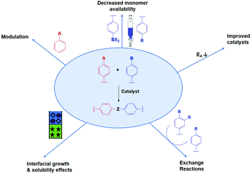
Several tactics have already been used to improve both crystallinity and porosity of COFs, resulting in higher quality materials. In the following we divide the used methods in seven different categories, of which the five most important ones are schematically illustrated in Fig. 8. It has to be noted that some papers reported combinations of different methods, if so we have put the discussion where most appropriate.First of all, and already applied successfully in the synthesis of 3D COF single crystals,3 is the insertion of monofunctional molecules. This process is called modulation and is expected to decrease nucleation as well as increasing error-correction.
Next is the decrease of monomer availability, which leads to slower reactions with less defects. This method can be performed using physical slow monomer addition (as shown in Fig. 8) or in situ monomer generation (e.g. by linker protection, chemical approach). While the latter is more elegant, the former has already proven its value in the synthesis of 2D COF single crystals.104
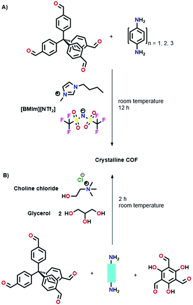
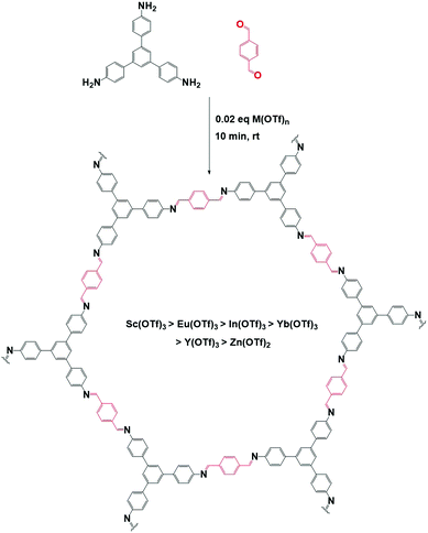
Many synthetic protocols for COFs use catalysts to increase error-correction and speed up COF formation. Most common are solvothermal acetic acid catalyzed protocols, for example in the formation of imine COFs. However, some other techniques have been reported recently. These include the use of Ionic Liquids (IL), Deep Eutectic Solvents (DES), advanced acid catalysts and others. As those improved catalysts lower the activation energy for COF formation, reversibility is increased.
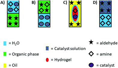
Interfacial growth and solubility effects can both improve COF quality by mitigating synthetic conditions. Due to reduced linker solubility or restriction of reaction to a specific interface, formation reactions are slowed down. Thus, less defects are formed resulting in high-quality thin films or powders.
Linker exchange can also be applied. Here, an initial (amorphous) network is formed, which is later transformed to a (more) crystalline COF by replacement of a linker by a new one. This way, new linkage types or previously inaccessible free functional groups can be obtained. As the COF is formed in a two-step process, conditions can be optimized to separate ‘difficult to crystallize’ steps from the crystallization.
Still, some other techniques remained undiscussed in this paragraph, most importantly linker and condition optimization. However, as these techniques are highly linker specific and can hardly be generalized, they are not the most attractive approaches to increase quality of the whole family of COFs. Still, some interesting effects and considerations are discussed in order to better understand COF chemistry.
Finally, there are some approaches that could not be assigned to one of the discussed categories. To be able to incorporate these, we created a category of other methods.
3.1 Modulation in COF synthesis
Modulation has been extensively studied in MOFs, offering – among others – possibilities to enforce kinetic and particle size control, ultimately yielding improved crystallinity.149 However, while promising, it has been relatively underexplored for COFs with only very few examples available in literature.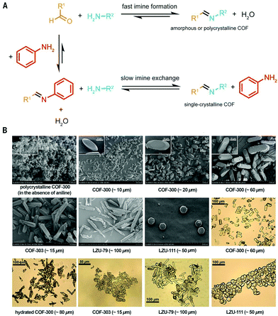 | ||
| Fig. 11 (A) Schematic representation of COF synthesis with and without aniline addition. Without the added modulator, COF formation is favored, resulting in fast nucleation and limited growth and thus amorphous or polycrystalline COFs. When sufficient amounts of aniline are added, an equilibrium is obtained, allowing the growth of large COF single crystals via slow imine exchange. (B) SEM and optical microscopy images of single-crystalline COFs. The SEM image of polycrystalline COF-300 is shown for comparison. Reproduced with permission from ref. 3, Copyright American Association for the Advancement of Science (2018). | ||
| Entry | Aniline (eq.) | Acetic acid solution | Time (days) | Temperature (°C) | Crystal size (μm) |
|---|---|---|---|---|---|
| Used conditions: 9.9 g adamantane-1,3,5,7-tetracarbaldehyde (0.04 mmol) in 0.5 mL 1,4-dioxane + aniline + acetic acid solution. Separate addition of 15.7 mg tetrakis(4-aminophenyl)ethylene) (0.04 mmol) in 1 mL 1,4-dioxane. Reproduced with permission from ref. 122, Copyright John Wiley and Sons (2020). | |||||
| 1 | 0 | 6 M, 0.1 mL | 5 | 120 | 0.2 |
| 2 | 7.5 | 6 M, 0.1 mL | 5 | 120 | 0.5 |
| 3 | 10 | 6 M, 0.1 mL | 5 | 120 | 1 |
| 4 | 12.5 | 6 M, 0.1 mL | 5 | 120 | 5 |
| 5 | 20 | 6 M, 0.2 mL | 7 | 120 | 10 |
| 6 | 40 | 6 M, 0.2 mL | 25 | 30 | 20 |
| 7 | 50 | 15 M, 0.2 mL | 25 | 30 | 50 |
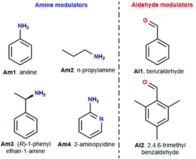
Meanwhile, experiments were performed with pre-modification of aldehyde monomers with the modulator, making in situ modulator generation via transimination possible. The synthesis of three different COFs (Fig. 12) by condensation of hydrazine hydrate with 1,3,5-triformylphenol (RIO-11), 1,3,5-triformylresorcinol (RIO-12) or 1,3,5-triformylphloroglucinol (RIO-13, 1,3,5-triformylphloroglucinol = TFPM) was studied for gaining insight on the influence of modulator and H-bonding effect.152 Without modulator (Am1) addition, a clear increase in crystallinity and porosity with additional OH-groups in the aldehyde monomer could be observed. However, when using a modulated approach, even RIO-11 could be reticulated in a highly porous and crystalline COF. Using the two step-approach (Fig. 12a) yielded a BET surface area of 1290 m2 g−1 and crystallite size of 64 Å, while the optimized one-step (Fig. 12b, 2 eq. of modulator) approach resulted in 1050 m2 g−1 for 60 Å crystallites (for comparison, an unmodulated synthesis of RIO-11 gave crystallites of 48 Å with BET surface area of 242 m2 g−1). However, when applying the same methodology to RIO-12 and RIO-13, no improvement (RIO-12) or even a decrease (RIO-13) in materials quality was observed, most likely resulting from the irreversible keto–imine adduct formation. Another study combined the aforementioned TFPM with benzidine to form TFPM-BZ COF via a two-step transimination (as illustrated in Fig. 12A) with different amines.153 Highly crystalline COFs could be synthesized at 180 °C and ambient pressure in only 6 h. BET surface areas of 1052.3 m2 g−1 (2-aminopyridin, Am4) and 1056.6 m2 g−1 (n-propylamine, Am2) could be obtained, much higher than the 537 m2 g−1 obtained by traditional solvothermal methods. Other modulators (n-butylamine, isobutylamine, n-hexylamine and dodecylamine) were also tested and all resulted in highly crystalline COFs. Albeit, it seemed that mono-amines with high boiling points gave the sharpest PXRD peaks. Finally, the approach was generalized to DHNDCA-TAPP COF (2,6-dihydroxynaphthalene-1,5-dicarbaldehyde, DHNDCA + 2,4,6-tris(4-aminophenyl)-pyridine, TAPP) which could not be synthesized via traditional methods.
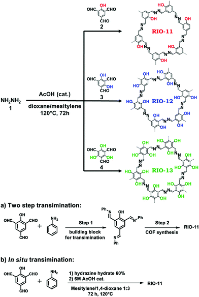 | ||
| Fig. 12 Synthetic scheme for RIO COFs (RIO-11, RIO-12 and RIO-13). Two different modulation approaches are shown: (a) two step transimination. (b) In situ transimination. Reproduced with permission from ref. 152, Copyright American Chemical Society (2018). | ||
Aldehydes can also be used as modulators, as has been shown for TAPB-BDA COF where the addition of Al1 was studied.155 A sharpening and increase of intensity of the (100) diffraction peak, as well as a decrease in FWHM, was observed on increasing modulator concentration, indicating an increase in crystallinity. N2-Sorption experiments confirm these results, as an increase in BET surface area from 1378 m2 g−1 (for unmodulated COF) to 2480 m2 g−1 (for 9 eq. of benzaldehyde), indicating a more ordered porous structure. A second COF, TAPB-TFPA (TFPA: tris(4-formylphenyl)amine) confirmed the generality of the approach as 4 eq. of modulator caused a threefold increase in both (100) peak intensity as BET surface area. However, no significant difference in crystallite size and morphology was observed for the modulated materials, implying that benzaldehyde modulators might not be the best choice for growing large COF crystals. One report studied the combined use of an aldehyde and amine modulator, namely Al1 and Am1 for TAPB-BTCA COF (BTCA: 1,3,5-benzenetricarbaldehyde) as shown in Fig. 13.154 12 eq. of both modulators were used in a Sc(OTf)3 catalyzed synthesis. While unmodulated samples formed irreversible polycrystalline aggregates, modulation allowed selective production of spheres, hollow fibres and films, depending on monomer concentration, solvent composition and supporting bases. Moreover, sharper and more intense PXRD peaks were observed and BET surface area increased from 432 m2 g−1 for the unmodulated material to 882 m2 g−1 for the modulated material. Crystallinity could be even further improved by increasing the amount of acid catalyst. Moreover, the crystallite size of 17.6 nm was significantly higher than the 10.7 nm obtained for the unmodulated material (via Scherrer analysis). Studies on the relative ratio of the PXRD reflections showed a critical amount of 12 eq. of monomer, as going from 0 to 12 eq. continuously enhanced intensity and sharpness of the (100) reflection, but sample yield declined dramatically when more than 12 eq. of modulator were used. The obtained results could be extended to different catalysts (acetic acid), aldehyde monomer (BDA) and amine monomer (p-phenylenediamine, PPD). A kinetic pathway was proposed, where, unmodulated COFs rapidly precipitate into amorphous polymers (kinetic traps, Fig. 13A) and then partially transform to thermodynamically favored crystalline materials (equilibrium state, Fig. 13A). When modulators are added, four different reactions can happen to any intermediate oligomer. A modulator can react with the oligomer to form IS-1 or IS-3 or it can react with one of the monomers to form IS-2 or IS-4. IS-1 can be converted to IS-2 due to the Schiff base reversibility, just as IS-3 and IS-4. As the latter (IS-2 and IS-4) can form crystalline COFs, they are thermodynamically favored, but both modulators are required to enhance the reversibility of all steps.
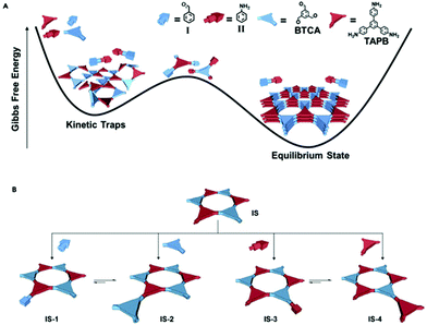 | ||
| Fig. 13 Modulated synthesis of TAPB-BTCA COF in a cartoon representation. Aldehydes are shown in blue (rod: benzaldehyde, triangle: 1,3,5-benzenetricarbaldehyde), amines in red (rod: aniline, triangle: 1,3,5-tris(4-aminophenyl) benzene. (A) Kinetic traps and equilibrium state in function of Gibbs free energy. (B) Different reactions possible and the formed structures. Reproduced with permission from ref. 154, Copyright Elsevier (2019). | ||
Structures could also be modified by modulator addition. For example, chiral TFPM-TAPB COF could be synthesized from achiral linkers (TFPM and TAPB) by addition of a chiral modulator (Am3).156 In another study, different mesocrystalline structures were formed by adjustment of the modulator (between n-propylamine, n-butylamine, n-hexylamine, n-octylamine, n-dodecylamine and aniline), while unmodulated synthesis only formed irregular aggregates.157 Moreover, by slight alteration of reaction conditions, complicated mesostructures could be formed. Finally, ultrathin nanosheets could be formed by the addition of 40 eq. of Al2.158 Even though the sheets are amorphous on PXRD (most likely due to the disordered stacking of the nanosheets), Selected Area Electron Diffraction (SAED) patterns were sharp and matching with the patterns observed for exfoliated “traditional” COFs and a periodic well-defined lattice (matching with the theoretical lattice) was observed in Scanning Tunneling Microscopy (STM). The technique was generalized for four different COFs and also works with bromo-2,6-dimethylbenzaldehyde as modulator. However, the use of 3,5-di-tert-butylbenzaldehyde, 2,6-dimethoxybenzaldehyde, and 3,5-bis(trifluoromethyl)benzaldehyde did not afford solid products, most likely because the substituted groups on the modulator impede nucleophilic attack on the intermediate compound.
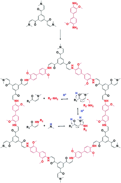 | ||
| Fig. 14 Structural representation of a COF (JUC-523)159 synthesized by Michael addition–elimination of a β-ketoenamine and an amine. The mechanistic pathway is shown in the pore. | ||
3.2 Decreasing monomer availability
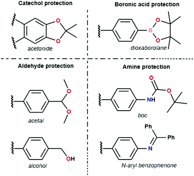
The first example of a protecting group used is the acetonide catechol.160 This method has been developed because of undesirable features in the polyfunctional catechols used in boronate ester COF synthesis, which are hard to dissolve and prone to oxidation. Contrarily, the acetonides have decreased polarity, show no auto-oxidation and have enhanced solubility. Efficient boronate COF formation from acetonides could be achieved by BF3.OEt2 catalysis. Three COFs (COF-5, COF-10 and NiPc-PBBA COF) prepared through this method have been compared to materials synthesized via direct condensation.161 No significant difference in quality between both methods could be found for COF-5 and COF-10 with sharp PXRD reflections and high porosity for all materials. However, for NiPc-PBBA COF, a modest improved in quality was observed, as shown by sharper PXRD reflections and a slight increase in surface area (776 m2 g−1vs. 624 for the direct condensation). It has to be noted that high catalyst loadings were necessary to synthesize these materials, which was attributed to complex formation between free boronic acids and BF3·OEt2. Still, as most boronic acids immediately rearrange to boroxines, this side reaction is not too problematic. Boronate ester COFs have also been reported from dioxaborolane protected boronic acids, which have improved solubility.162 Subsequent reaction was done in two steps under microwave addition. In a first step the dioxaborolane was heated with HCl for 10 minutes. Afterwards the catechol was added and the COF was left to form over 30 minutes. While high porosity and sharp PXRD reflections were observed using this method, one-pot deprotection turned out to be challenging.
Aldehydes used for COF formation have been protected as acetals163 and in situ generated by the oxidation of alcohols.164 The former has been proven to work for imine, azine and hydrazone COFs, while the latter was used in the synthesis of Crystalline Triazine Frameworks (CTFs). Advantages of acetal protection are enhanced solubility and stability. Also, Electrospray Ionization Mass Spectrometry (ESI-MS) measurements did not find aldehyde in the reaction mixture, indicating direct condensation of amine and acetal.163 Highly crystalline and porous LZU-20, LZU-21 and LZU-22 were synthesized using this method. Alcohols could be used for synthesis of CTF-HUST-C1, CTF-HUST-C5, CTF-HUST-C6 via slow oxidation in DMSO.164 Using FTIR measurements at different times in the reaction, it could be noticed that characteristic triazine peaks emerged as alcohol peaks disappeared, proving that the alcohol oxidation was the rate limiting step. It was also noted that careful temperature control was needed to obtain high-quality material, initial low temperatures ensured slow initial nucleation, subsequent higher temperatures provided faster growth. Three different crystalline CTFs were obtained using this method, which is quite remarkable given the enormous difficulty in obtaining crystalline CTFs.141
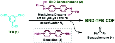
The tert-butyloxycarbonyl (boc) group is one of the most widely utilized amine protection groups.165 Therefore, it is no surprise that it has found use in the synthesis of COFs.83 In the synthesis of the woven COF-112, boc protection is used to guide the reaction via the “right” pathway, as shown in Fig. 16. Initial rapid imine condensation forms NHBoc-DIP, but cannot continue to an amorphous polymer because the second amine function is boc protected. This enables the coordination of Co2+ and formation of the Co(NHBoc-DIP)2(BF4)2 complex which already has the desired symmetry. Finally, the in situ deprotection of the amines by trifluoroacetic acid can react with the remaining aldehydes to form the crystalline COF. COF-112 could also be made from previously synthesized Co(NH2-DIP)2(BF4)2 but the boc protected group gave larger crystallites which could be analyzed by 3D-EDT. The method has also been extended to an isostructural iron based wCOF (COF-112-Fe) and three imine COFs (LZU-1, TFPB-BDA and Por-COF). The imine COFs could be obtained as highly uniform nanocrystals using microwave synthesis in ethanol. LZU-1 nanoparticles of 245 ± 25 nm (SEM) could be obtained with clearly visible pores (HR-TEM). Moreover, a BET surface area of 729 m2 g−1 was obtained (while the original report of LZU-1 gave 457 m2 g−1) indicating the high crystallinity of this COF. Finally, N-aryl benzophenones, which are common intermediates in the synthesis of aryl amines, could also be used in COF synthesis.166 Advantages of this protection include enhanced solubility, less danger of oxidation and easier purification than what is observed for amines. BND-TFB COF (N-benzidine benzophenone + BTCA) was prepared using microwave irradiation and traditional methods; results for different methods are summarized in Table 2. Comparing direct reaction (entry 10) to protected amine (entry 2), a clear difference (1501 and 2314 m2 g−1, respectively) is observed, showing the improved quality of the material synthesized from the protected monomer. Additionally, good quality (entry 1, 1938 m2 g−1) is already obtained after 24 h and when left for five days the quality improves even further (entry 3, 2618 m2 g−1). Microwave irradiation made it possible to obtain high-quality COF in seven hours (entry 9, 2200 m2 g−1) and moderate quality in as fast as 1 hour (629 m2 g−1). Moreover both vacuum activation (entry 4, 2313 m2 g−1) and reaction upscaling (entry 6, 2321 m2 g−1) do not cause any problems. Finally, oxidation resistance of the benzophenone was confirmed using reactions under air and under vacuum (entries 5 and 7). As air environment did not cause significant differences in quality (2327 m2 g−1) and vacuum even a diminishment (1677 m2 g−1), it was concluded that all reagents and intermediates were stable to oxidative degradation. Finally, any modulating capabilities of the generated benzophenone were ruled out as separate addition of this did not change the quality of the synthesized COF (entry 11, 1453 m2 g−1). The method was generalized to three other COFs (TpPA-1, TFPM-BZ COF, TAPB-BDA COF), which showed a slightly improved surface area and sharp PXRD reflections when the N-aryl benzophenone was used.
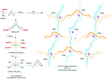 | ||
| Fig. 16 Synthetic scheme for the synthesis of COF-112 via boc protected amines. Adapted and reproduced with permission from ref. 83, Copyright American Chemical Society (2017). | ||
| Entry | Deviation from conditions | Time | S BET (m2 g−1) |
|---|---|---|---|
| Activation was done using supercritical CO2 unless otherwise specified. Reproduced with permission from ref. 166, Copyright American Chemical Society (2017). | |||
| 1 | — | 24 (h) | 1938 |
| 2 | — | 3 (days) | 2314 |
| 3 | — | 5 (days) | 2618 |
| 4 | Vacuum activation | 3 (days) | 2313 |
| 5 | Under air | 3 (days) | 2327 |
| 6 | 15×, vacuum activation | 3 (days) | 2321 |
| 7 | Under vacuum | 3 (days) | 1677 |
| 8 | Microwave, under air | 1 (h) | 629 |
| 9 | Microwave, under air | 7 (h) | 2200 |
| 10 | 3 used instead of 2 | 3 (days) | 1501 |
| 11 | 3 used with 2 eq. of 4 | 3 (days) | 1453 |
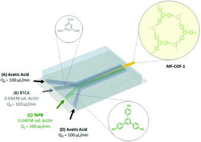 | ||
| Fig. 17 Schematic representation of microfluidic COF synthesis. Adapted and reproduced with permission from ref. 169, Copyright Royal Society of Chemistry (2016). | ||
As described in Section 2.1, slow monomer addition has been used for the synthesis of large single crystals of 2D COFs.104 First, stable COF-5 colloids of 400 nm were formed in ACN. Subsequently, this suspension was heated to 85 °C and linker solutions were added simultaneously. When monomers were added slowly (0.1 eq. per h), the average crystal size gradually increased up to 1 μm (Fig. 6E). However, when the rate of linker addition was increased to 1.0 eq. per h the particle size gradually decreased to finally settle around 50 nm. Most likely, the concentration barrier for nucleation was crossed in the fast addition growing regime. The critical monomer concentration could be estimated around 1 mM by the diversion point in Fig. 6E. WAXS measurements (Fig. 6F) confirmed the increased crystallinity of the particles during slow addition, as PXRD reflections intensified and sharpened, indeed particles seemed single-crystalline on HR-TEM. The method was also generalized to two other boronate ester COFs (COF-10, up to 190 nm and TP-COF, up to 750 nm). However, due to aggregation, the single crystalline nature of TP-COF could not be confirmed via HR-TEM. In 2019, the method was extended to 2D imine COFs.170 Crystalline colloids of three different imine COFs were stabilized in ACN solutions. Sizes and crystallinity could be controlled by the initial monomer concentration, with higher concentration resulting in increased particle size and crystallinity (TAPB-BDA COF for example could reach 330 nm at initial TAPB concentration of 4.25 mM). This was attributed to the typical re-crystallization of amorphous polymer processes in imine COFs, which is more efficient when larger amounts of linkers are present. Subsequent monomer addition afforded particles of up to 690 nm for an adding rate of 1 eq. per h. Surprisingly, when monomers were added more rapidly (50 eq. per h), particle size increased initially (up to two added eq.) to 490 nm. Only when more monomers were added, particle size started to decrease (up to 230 nm for 6 eq.) due to the nucleation of new crystallites. However, no associated change in WAXS (100) diffraction peak FHWM with particle growth was observed, indicating that the domain size was left unchanged. Most likely the newly added monomers form an amorphous shell around the colloid, which slowly recrystallizes over time.
3.3 Improved catalysts
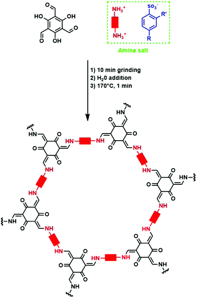
Alternatively, p-toluenesulfonic acid (PTSA) and derivatives could be used as both catalyst and molecular organizer. In a first study, PTSA was used to obtain 12 different COFs with high surface areas and crystallinity in very short timeframes. Moreover, the synthesis could be performed on a 10 g h−1 scale using a twin screw extruder.182 For this, the used diamine was first reacted with PTSA to form an amine salt. Subsequently, TFPM was added to the mixture and grinded for 10 minutes. Finally, 100 μL H2O was added and the mixed mixture was heated at 170 °C for one minute to obtain the COF. The whole procedure is shown schematically in Fig. 20. The material was isolated in high yield after dipping in hot water for five minutes. PXRD analysis revealed high intense (100) reflections and BET surface areas of up to 3000 m2 g−1 could be obtained, sometimes two to three times higher than previously reported values for these COFs.182 Mechanistic studies revealed the importance of H-bonding in this process. When PTSA and the amine react, a H-bonded lamellar structure is formed, acting as a template for 2D COF formation. Later on, when TFPM is added, it can easily exchange PTSA due to the similar size of both compounds, in order to form crystalline COFs. Indeed, when other acids (phosphoric acid, trifluoromethyl carboxylic acid, 2-aminobenzenesulfonic acid, phenol sulfonic acid, 4-nitrobenzenesulfonic acid or benzenesulfonic acid) were used, much lower surface areas and crystallinity were observed, indicating the crucial role of molecular orientation and geometry in the formed amine salt. The influence of the amine salt structure on COF properties has been studied in more detail in a follow-up report, where the combination of TFPM with 11 different amines in presence of five PTSA derivates was followed.183 It was observed that in the formed amine salts, every amine functionality (NH3+) was surrounded by three H-bounded (Namine–H–Oacid) acid molecules, forming a 1D lamellar structure. After aldehyde addition, these H-bonds can compete with imine formation, indicating the importance of controlling H-bond strength, as too weak H-bonds might not compete enough, while too strong H-bonds can impede COF formation. Indeed, a clear interaction between surface area and H-bond distance was observed, with an optimal distance between 2.06 and 2.19 Å resulting in COFs with the highest percentage of theoretical surface area.
Finally, trifluoromethanesulfonic acid could be used to synthesize CTFs at room temperature or via microwave radiation. Most notable advantages of this technique are the absence of metal/salt contamination, and the possibility to obtain colored materials incorporating functional groups that could not withstand the harsh conditions typically used. However, pore sizes are moderate to low and only a few microwave-synthesized materials showed some crystallinity. Still, this indicates that an acid catalyst and high pressure could reach some reversibility at quite low temperatures.184
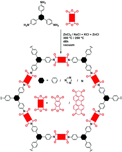 | ||
| Fig. 21 Schematic representation of imide COF synthesis in ZnCl2. Black hexagons represent the different moieties used as amine, red rectangles the different dianhydrides. | ||
Base catalyzed imine COF formation was proven possible for four different materials.186 However, it has to be noted that a phenol function on the aldehyde linker is necessary for this protocol. An aqueous solution of aldehyde and KOH was prepared to which the amine was added in organic solvent (N,N-diethylformamide, DEF or N,N-dimethylformamide, DMF). Sharp PXRD reflections and moderate porosities were obtained, however, materials prepared using PTSA catalysis (as explained in Section 3.3.2) were of better quality. It was also observed that a large interval for crystallinity existed, as the concentration of KOH could be altered between 2 and 6 eq. and the DEF/H2O ratio between 1/1 and 3/1 to yield highly crystalline compounds. Moreover, KOH and CsOH could also be used, with the main difference being the salt formed by combination of base and phenol containing aldehyde. Highly soluble salts were preferred, which were then slowly reacted to imines in a large excess of water.
Another method used compressed CO2 in H2O as solvent for COF formation, which is obviously an attractive option due to environmental reasons.187 Most likely, in situ formation of acidic H2CO3 is important to catalyze the COF formation, but the low viscosity of this solvent might also be important, as pure aqueous acetic acid solutions did not yield crystalline materials. LZU-1 was prepared in 24 h at room temperature and could easily be obtained by CO2 depressurization. An increase of crystallinity with CO2 pressure was observed, with sharper and more intense (100) reflections, 4.5 MPa was used as an optimized value. While BET surface areas for lower (2.4 and 3.5 MPa) CO2 pressures were very low (23 and 42 m2 g−1 respectively), a value of 678 m2 g−1 was obtained at 4.5 MPa, which is significantly higher than the 410 m2 g−1 for the 'classical' solvothermally synthesized material.
3.4 Interfacial COF growth and solubility dependency
While solvent selection and ratios have decisive roles in the crystallization of COFs, not many systematic studies have been performed on the effect of solvents on COF quality and the underlying mechanisms. Most often trial-and-error approaches are used to select appropriate solvents, loosely based on conditions used in the first reports. For example, mesitylene/dioxane mixtures are commonly used in order to control linker solubility and slow down the reaction.1,23 One theoretical study reported a difference in binding energy in different solvents,107 which theoretically can lead to the growth of large single crystals.188 But no direct origin for the obtained values could be found.107 A more recent example is the “ventilation vial” approach to COF-300, using a cyclohexane and 1,4-dioxane mixture as reaction solvent.189 During reaction, dioxane is vented out of the mixture, generating a gradient of acidity and polarity over time. This reduces solubility and increases acidity, leading to highly crystalline COF. The method could easily be scaled up to two gram scale. Finally, it has been shown that both boroxine e.g. COF-5)109 and imine COFs e.g. TAPB-BDA COF)170 can be stabilized as colloidal suspensions by using Lewis basic solvents (e.g. ACN), as already discussed in Section 2.1.However, most of the studies regarding solubility have been focused on thin film growth. Multiple reports have shown that highly crystalline thin films can readily be obtained by interfacial COF growth. In a first report, a solution of linkers in CHCl3 was carefully put on a water layer, synthesizing the COF at the air/water interface.190 Overnight a smooth polymer layer was formed, but no crystallinity or porosity was reported, indicating insufficient reversibility or too fast COF formation. In later reports, this issue was solved by the separation of reagents and/or catalyst in different phases with COF formation on the interface. These procedures are schematically shown in Fig. 22.
A first approach (Fig. 22A) was based on the earlier mentioned PTSA catalyzed COF synthesis (Section 3.3.2). Aldehyde linkers were dissolved in dichloromethane (DCM), followed by addition of H2O as spacer and finally a H2O solution of amine salt was put on top.191 A thin film of Tp-Tta or Tp-Ttba is formed at the interface over 72 hours at room temperature. Crystalline films could be obtained due to the intermediate layer of pure H2O, which slows down the diffusion of linkers to the interface even more. This way, sharp PXRD reflections and surface areas which are among the highest values noted for 2D thin films are obtained. Four different COFs were tested for this method and film thickness could easily be varied (from 50 nm to a few μm by changing monomer concentration. Finally, SEM analysis showed that fibers are formed rapidly (1 h), which slowly assemble to crystalline sheets (from 24 h onwards). The other catalyst mentioned in Section 3.3.2, Sc(OTf)3, could also be used for thin film synthesis (Fig. 22B).179 Here, both precursors (aldehyde and amine) could be dissolved in organic solvent, while the catalyst resides in the water layer. After 72 h, thin films of TAPB-BDA COF could easily be separated from the mixture using tweezers. Again, film thickness could be controlled by varying monomer concentration, opening a range from 20 nm to 100 μm. However, it has to be noted that reaction times increased for thinner films. Remarkably, even thinner films (up to 2.5 nm) could be formed rapidly by the use of very small amounts of organic solvent, but no crystallinity could be obtained for those films. The same procedure was also used to prepare thin films by Suzuki polymerization.192 Again, both linkers where in the organic phase, while the catalyst (K2CO3) was dissolved in H2O. Suzuki reactions are very attractive due to the wide scope of available monomers, mild conditions and resulting strong C–C bonds. However, the irreversibility of this reaction makes it fundamentally difficult to apply in COF synthesis. Indeed, no crystallinity could be observed in XRD analysis of the resulting materials. Still, HR-TEM analysis showed periodicity and a layered structure, indicating some order in small domains. Fig. 22C illustrates a method to grow COF thin films with the use of hydrogels.193 First, a solution of amine in aqueous acetic acid was allowed to be incorporated in a hydrogel. Subsequently, the swollen hydrogel was put in an oil solution of aldehyde linker and a small amount (10 μL) of H2O was added. Thin films with thickness of 4 to 150 nm (by monomer concentration variation) formed over 12 h at the oil/water/hydrogel interface. Observed XRD reflections were in good agreement with previously obtained PXRD patterns for COF TTA-DHTA and allowed to calculate a grain size of 27.5 nm ± 0.4 nm. Thin film synthesis was also attempted at a liquid/liquid interface, but obtained products were amorphous. This was attributed to delayed diffusion by the hydrogel as amine diffusion only reached equilibrium after 1 h. Very recently, COF thin films have been synthesized at the interface of an amine in H2O solution with an aldehyde/catalyst mixture (octanoic acid was used as a catalyst), as illustrated in Fig. 22D.194 No organic solvents were needed as the aldehyde could directly be dissolved in the catalyst. This led to rapid formation of an amorphous thin film at the interface, which subsequently acted as a diffusion barrier. The resulting decreased linker concentration in combination with the strong affinity of NUS-9 to the used solvents resulted in slow exchange to highly crystalline membranes.
3.5 Exchange reactions
Exchange reactions in COF formation can be separated into two distinct categories with different goals. In amorphous to crystalline exchange, the exchange is the deciding factor to reach crystallinity. This is highly advantageous for creating COFs with unique morphologies or composite materials. First, an amorphous polymer is rapidly formed in the desired morphology, which is then allowed to slowly exchange to a crystalline COF overtime. Crystalline to crystalline exchange however can be used to incorporate linkages which are not directly accessible for COF synthesis or yield materials with low crystallinity. Initially, a highly crystalline COF is formed of which some linkers are later exchanged to the desired (functional) linkers, often obtaining increased crystallinity.Zhang et al. found out that, while COFs cannot be used directly for 3D printing, this was possible for the amorphous polymers initially formed.197 Linkers, PTSA and Pluronic® 127 (F127) were mixed in H2O/THF solution, out of which the THF rapidly evaporated. The resulting hydrogel was used for 3D printing of a pyramid, which was heated to 90 °C for 24 h to remove F127 and later on crystallized in dioxane/mesitylene at 150 (72 h, acetic acid catalyst, annealing). TpPA-1 and TpPA-2 (or 3D-TpBD-Me2) were synthesized with comparable crystallinity and surface area as the pristine materials, the process and resulting PXRD pattern can be found in Fig. 23a and c, respectively. 3D-TPE-COF was also tested, but needed modulator addition to slow down the synthesis enough to allow 3D printing (Fig. 23b and d). Finally, it was shown that different COFs could be combined and bound at the interface, suggesting connections at the molecular level, while even retaining some crystallinity (Fig. 23e–g).
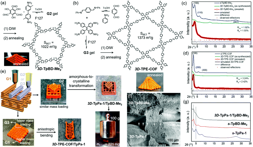 | ||
| Fig. 23 (a and b) Schematic representation of the used procedure for 3D printed β-ketoenamine COF (3D-TpBD-Me2) and imine COF (3D-TPE-COF). (c and d) PXRD patterns of as-synthesized and annealed β-ketoenamine and imine COF. (e) Heterogeneous printing of two different COF and their obtained lattices (3D-TpPa-1/TpBD-Me2) and (3D-TPE-COF/TpPa-1), the materials could withstand anisotropic bending and a weight of 100 g. (f) SEM image of the interface of heterogeneous 3D-TpPa-1/TpBD-Me2. (g) PXRD patterns of pristine TpBD-Me2 and TpPa-1 compared to the pattern of heterogeneously printed 3D-TpPa-1/TpBD-Me2. Reproduced with permission from ref. 197, Copyright American Chemical Society (2019). | ||
Crystalline COFs could also be prepared by linkage type substitution from amorphous porous organic polymers (POPs).198 In a first step, imine and imide linked POPs were prepared, to which dialdehydes and dianhydrides were added respectively. When these mixtures were put in typical COF growth conditions for the desired linkage type, crystalline COFs were obtained (Fig. 24). Crystallinities and porosities for all obtained materials were high, Exch-COF-1 and Exch-COF-4 even showed much higher BET surface areas than could be obtained by direct synthesis (1089 vs. 796 m2 g−1 for Exch-COF-1 and 2238 vs. 1700 for Exch-COF-4). However, it has to be noted that linker exchange with terephtaldehyde from the polyimine was not successful, possibly due to the high stability of the imide bond. The used OH-functionalized aldehydes could overcome this issue by non-covalent stabilization of the imine bond. The formation of COF-1 could be tracked over time with FTIR, SEM, PXRD and N2-sorption, showing that while transformation started fast (appearance of a weak diffraction peak after 2 h), it was only complete after five days.
In another study, two imine COFs based on the condensation of BTCA with PPD (COF-Ph) and 1,4-diaminonaphthalene (COF-Naph) were studied.200 Interestingly, while COF-Naph crystallized as a dense material, hollow particles were obtained for COF-Ph. Next, COF-to-COF transformation was performed, different equivalents of 1,4-diaminonaphthalene were added to COF-Ph. It was observed that both porosity and crystallinity improved as a result of the transformation, with sharper PXRD reflections and higher BET surface areas for higher amounts of 1,4-diaminonaphthalene. NMR and TEM analysis showed that benzene and naphtalene rings were homogeneously mixed in the resulting material. In contrast, when PPD was added to COF-Naph, the dense starting material transformed to hollow spheres with small rod-shaped crystals embedded on. Additionally, NMR analysis revealed separate domains of COF-Ph and COF-Naph in the material. Still, both crystallinity and porosity improved in comparison to the parent material. Finally, it was observed that it was harder to exchange 1,4-diaminonaphthalene to PPD due to the strong π-stacking interactions in COF-Naph. This resulted in relatively less exchanged linker and even dissolution of the COF when too large an excess of PPD was used.
It was also proven possible to change linkage type by COF-to-COF transformation. This has been shown for the transformation of imine to β-ketoenamine linkages, as shown in Fig. 26.201 As imine formation is more reversible, this allows to obtain the highly stable β-ketoenamine linkage with improved crystallinity. Interestingly, a partly imine, partly β-ketoenamine linked material could be obtained by using 0.5 eq. of TFPM. However, the best porosity was obtained with exactly one equivalent, indicating that this is enough to perform the enamine-forming tautomerization step. The method resulted in sharper PXRD reflections and higher BET surface area (1536 m2 g−1 instead of 1102 m2 g−1 obtained by benzophenone monomer protection (as mentioned in Section 3.2.1) for BND-TFPM COF. Moreover, as a control experiment, β-ketoenamine COF was prepared from benzaldehyde protected amines, mimicking the transimination without the effect of pre-made frameworks. As both crystallinity and porosity for this control turned out to be decreased in comparison to the monomer exchange method, it was concluded that the pre-made COF framework was important to reach high-quality material. Comparable results were obtained for a recently published imine to amide exchange method, converting a reversible linkage to an irreversible variant for the first time.180 Here, the initial 4,4′-biphenyldicarboxaldehyde was exchanged with terephthaloyl chloride to form a highly stable amide COF. It has to be noted that it was impossible to build the obtained amide COF via direct condensation. For optimized results, the initial imine COFs were synthesized using ScOTf3 as a catalyst since the H2O in the commonly used aqueous acetic acid solution has a negative influence on the acid chloride used in the amide exchange reaction. Additionally, a longer aldehyde (more phenyl rings) was exchanged by a shorter acid chloride, to promote the reaction by insertion of a more nucleophilic building block. When 1 eq. of terephthaloyl chloride was used at low temperature (0–4 °C) in presence of triethylamine, a highly crystalline amide COF was formed in two days. This was confirmed by high-performance liquid chromatography (HPLC) analysis of the reaction mixture before and after exchange, showing that 4,4′-biphenyldicarboxaldehyde replaced almost all terephthaloyl chloride after two days, while no concentration change was observed when no terephthaloyl chloride was added. Interestingly, more equivalents of terephthaloyl chloride or higher exchange temperatures resulted in dramatically reduced intensity of PXRD reflections. Finally, it has to be noted that both crystallinity (a tenfold increase in the main PXRD reflection) and porosity (156 to 261 m2 g−1; while direct synthesis of the amide COF gave a material with a surface area of 33 m2 g−1) increased from imine to amide COF.
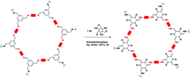 | ||
| Fig. 26 Schematic representation of the synthesis of β-ketoenamine COF by linker exchange from imine COFs. | ||
Technically, the transformation of 1D ribbons to 2D COFs can also be seen as a COF-to-COF transformation via linker exchange.76 While no linkers are removed from the framework, new linkers are added, connecting the ribbons to form crystalline COFs. First, 1D ribbons were formed by the condensation of 1,3,6,8-tetrakis(p-formylphenyl)pyrene (TFPPy) and TFPA in the presence of p-toluidine as a modulator, rendering a network with unreacted amino groups (COF-76) (Fig. 27A). Here, cylindrical pores with 12 Å diameters are already observed, as well as amine–imine interactions (dH–N) = 3 Å, resulting in a BET surface area of 860 m2 g−1. Next, COF-76 was reacted with a dialdehyde or dianhydride to form an imine (COF-77) or imide (COF-78) linked COF, respectively (Fig. 27B). This transformed the 1D ribbons into 2D COFs with the appearance of a new type of pore (diameter ≈ 20 Å), resulting in increased BET surface areas (1288 m2 g−1 and 1080 m2 g−1, for COF-77 and COF-78, respectively). It has to be noted that COF-77 and COF-78 could also be formed by direct, in situ, condensation (Fig. 27C) with comparable crystallinity and porosity to the stepwise synthesis (BET surface area of COF-78 from in situ synthesis was even slightly higher, 1265 m2 g−1).
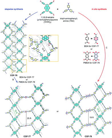 | ||
| Fig. 27 Schematic route for the synthesis of COF-77 and COF-78. These materials can be obtained stepwise via 1D ribbons (A and B) or in situ (C). Atom sphere colors: C, gray; N, blue; O, red. Hydrogen atoms, except for aldehyde- and amine-hydrogens, are omitted for clarity. Reproduced with permission from ref. 76, Copyright American Chemical Society (2020). | ||
3.6 Linker and condition optimization
Much research has been done on optimizing linkers and conditions in order to find combinations resulting in the highest quality. However, most often, these methods cannot be generalized as they are highly dependent on the used linkers or based on easy to crystallize linkers. Still, the following section will give a short overview of interesting observations.Firstly, planarity of the linker is a deciding factor in quality of the resulting COF. It has been observed that linkers incorporating the more planar triazine ring afford materials with higher crystallinity and porosity than phenyl ring based linkers.202–206 In Fig. 28B and C the reduced planarity of the phenyl core and its effect on the stacking energy is shown. This leads to less intense (100) PXRD reflections and slightly deformed crystallites (Fig. 28B and C). Moreover, the use of triazine rings makes it possible to induce donor acceptor stacking, which is more energetically favorable than π–π stacking.204 It has to be noted that this observation is not limited to triazine/phenyl building blocks. In fact it has been shown that functionalization of a phenyl ring causes similar effects.207 Another important factor is the rigidity of the building blocks, as more flexible linkers lead to more possible conformations and thus lower crystallinity.208,209 However, both effects can be countered by the introduction of extra favorable interactions like hydrogen bonding.152,210–212 an effect that can be assigned to conformational locking152,212 or interlayer stabilization.210,213 Both modes of favorable hydrogen bonding are shown in Fig. 29. Still, one has to be careful not to decrease symmetry, as it has been observed that this can reduce both crystallinity and surface area.152,203,214 Additionally, partial linker fluorination can greatly improve both crystallinity and porosity as it induces strong phenyl–perfluorophenyl interactions.215–217
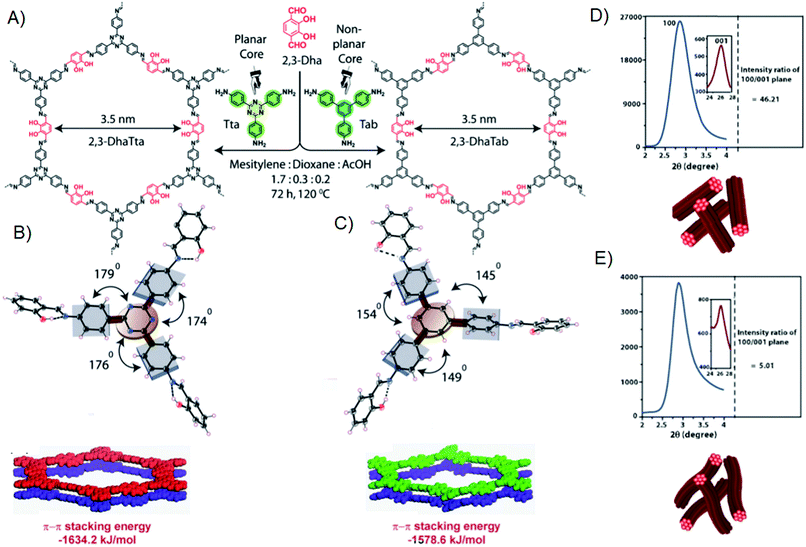 | ||
| Fig. 28 (A) Schematic illustration of the synthesis of a planar (2,3-DhaTta) and non-planar (2,3-DhaTab) COF. (B and C) ORTEP diagrams of model compounds using planar (B) and non-planar (C) amine and the resulting π–π stacking energy for the layers. (D and E) PXRD(100)/(001) intensity ratios for planar (D) and non-planar (E) amines and morphology of the obtained crystallites. Reproduced and adapted with permission from ref. 202, Copyright John Wiley and Sons (2016). | ||
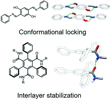 | ||
| Fig. 29 Two modes of favorable hydrogen bonding in COF crystallization. Coplanar hydrogen bonding induces conformational locking of the imine bond, while intralayer hydrogen bonding induces strong interactions between the layers. Reproduced and adapted with permission from ref. 213, Copyright American Chemical Society (2020). | ||
A completely different approach is based on the reduction of possible stacking modes.218–220 By intelligent choice of COF building blocks it is possible to induce geometrical constraints and by consequence increase crystallinity. This has been illustrated in Fig. 30, which shows “propeller” and “armchair” conformations on an example of TFPPy. Both conformations could induce specific stacking modes, reducing defects and thus increasing crystallinity. Moreover, the information can be transferred to neighboring building blocks in the same layer, if the appropriate linker is used. On the one hand, it was found that for “propeller” forming monomers, like ETTA, twisted building blocks were needed to impose correct steric limitations by phenylene tilt.219 On the other hand, TFPPy was experimentally found to prefer an “armchair” mode. Consequently, flat and rigid building blocks were needed to synchronize all monomers.218 Together, these effects impose serious limitations on the degrees of freedom of the system, resulting in increased crystallinity with domain sizes up to 500 nm. Alternatively, strong dipole interactions can also induce such directed growth by the appearance of favorable stacking interactions.221 Another example of directional uniform growth inducing crystallinity has been considered in a theoretical study.222 Here monomer, dimer, trimer and hexamer monomers were compared. It was found that the hexamer building block, which can de facto be seen as one pore of a hcb net, tended to grow uniformly in all directions. Therefore, less defective 5- and 7-membered rings were formed and crystallinity was improved.
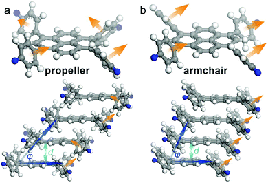 | ||
| Fig. 30 COF building blocks imposing geometrical constraints when incorporated into COF (C, gray; H, white; N, blue), illustrated by TFPPy. Two conformations are shown: (A) propeller: the normal vectors of the phenylenes describe a circle, which induces offset stacks of alternated left- and right handed propellers. (B) Armchair: the normal vectors of the phenylenes point in the same direction, stacking in slip-stacked columns. Reproduced with permission from ref. 218, Copyright American Chemical Society (2016). | ||
It has to be noted that all previously described effects are primarily based on interlayer stacking interactions and are thus less (or even not) valid for 3D COFs. The following observations can be extended to both 2D and 3D materials. For example, it has to be taken into account that when linker length is increased, the reaction time to obtain crystalline materials will also increase.103,138 Additionally, it might be advantageous to develop monomers which can perform self-condensation, as depicted in Fig. 31.223–225 Besides the guarantee of correct stoichiometry, the main advantage of this method is its surprising solvent adaptability. It has been shown that this method could be used to obtain highly crystalline Py–Py–COF, A2–B2–COF and BBO–COF, not only in typical COF solvent mixtures (dioxane/mesitylene, DCB/n-butanol) but also in a range of pure organic solvents (dichloromethane, tetrahydrofuran, ethanol, acetonitrile, etc.). This solvent adaptability was not observed for the related materials obtained by co-condensation and might be related to the absence of need for matching linker solubilities. Moreover, materials quality was observed to be improved if self-condensation was used, with sharper PXRD reflections and higher surface areas.
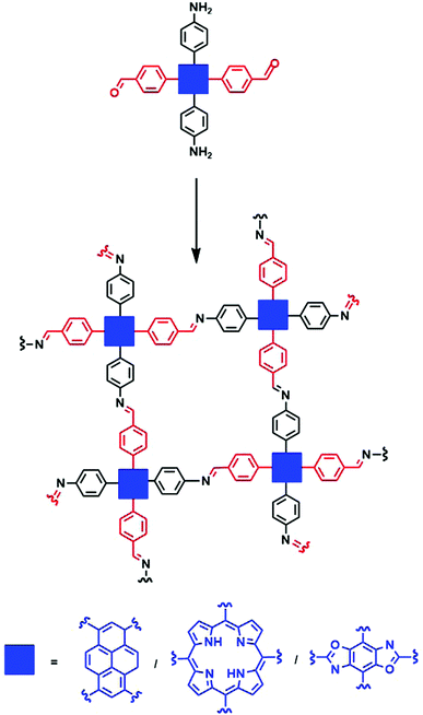 | ||
| Fig. 31 Schematic representation of COF monomers capable of performing self-condensation. A monomer containing both amine and aldehyde functions is polymerized to an imine COF. | ||
3.7 Other methods
Some techniques to prepare high-quality COFs could not be placed in one of the afore mentioned categories and will thus be discussed in the following.For example, often used to increase reaction speed is microwave COF synthesis. Additionally, COF synthesis in microwaves allows continuous reaction monitoring and high controlability of reaction temperature and pressure, even in the center of reactions.226 Since the first report, microwave irradiation has been used to obtain COFs with a wide variety of linkage types (e.g. boroxine,226,227 imine,228 β-ketoenamine,229 imide230) in times as little as 20 minutes. Moreover, in some cases, the quality of the resulting material can be higher than solvothermally synthesized COFs.229 Similarly, a Parr reactor could be used to synthesize crystalline amide linked COFs. A pre-made amorphous amide polymer could be crystallized by three day reaction with 10 eq. H2O at 250 °C and 10−4 mbar in a water-containing Parr reactor.47
Another often used technique is (Liquid Assisted) Mechanochemical Grinding, which is simple, fast and both economically and ecologically attractive.231 This process can be performed completely solvent-free,231 or by addition of catalytic amounts of solvents.232 However, the obtained materials show inferior qualities with moderate crystallinity and low surface areas.231–234
Additional to the techniques already mentioned in Section 3.4, high-quality COF thin films could be obtained by room temperature vapor deposition235 or growth on single layer graphene.236
Finally, in some cases it was proven possible to obtain crystalline materials resulting from almost purely irreversible reactions. Those can be roughly divided in three categories: (1) materials formed by reversible linkages, that are subsequently transformed to an irreversible, more stable linkage. Which is technically a crystalline to crystalline transformation as the ones shown in Section 3.5.2 but without exchange of linkers. (2) Activation of monomers to achieve quasi-reversibility. (3) Decreasing the degrees of freedom, which has also been done (to a certain amount) to increase crystallinity of reversible linkages (as discussed in Section 3.6. A recent review by Haase and Lotsch covers this approach in much greater detail.237
The most famous example of the combination of reversible and irreversible reactions are the β-ketoenamine TpPA-1 and TpPA-2 COFs that were already extensively discussed before and is illustrated in Fig. 32A.35 A highly reversible imine condensation is formed by an irreversible keto–enol tautomerization to create a highly stable and highly crystalline material. Alternatively, COFs could be formed by multicomponent reactions, forming several covalent bonds at once via a combination of reversible reactions. This resulted in an imidazole COF formed by the Debus–Radziszewski reaction, formation of this COF is schematically presented in Fig. 32B.238 Other examples of this approach include the post-modification of imine linkages to amide (as shown in Fig. 32C),48 carbamate,239 quinoline240 and thiazole.241,242 These post-synthetic linkage modifications have been excellently covered in a number of recent reviews.237,243
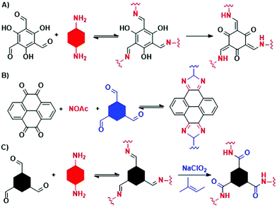 | ||
| Fig. 32 Three different combinations of reversible and irreversible reactions to form COF. (A) β-Ketoenamine COFs are formed by a reversible imine condensation followed by an irreversible keto–enol transformation.35 (B) A highly stable imidazole linked COF is obtained by the simultaneous formation of different covalent bonds via reversible reactions.238 (C) An imine linked COF is post modified via an irreversible reaction to form a stable amide linkage.48 | ||
Monomer activation has been used for crystalline C![[double bond, length as m-dash]](https://www.rsc.org/images/entities/char_e001.gif) C linked materials by Knoevenagel condensation. A cyanide functionality on the nucleophile stabilizes the intermediate carbon anion, resulting in partial reversibility.44,244 Alternatively, cyanide functionalized methylpyridines,245 methyltriazines50,51 or even in situ trimerized acetonitrile246 could be used.
C linked materials by Knoevenagel condensation. A cyanide functionality on the nucleophile stabilizes the intermediate carbon anion, resulting in partial reversibility.44,244 Alternatively, cyanide functionalized methylpyridines,245 methyltriazines50,51 or even in situ trimerized acetonitrile246 could be used.
Finally, crystalline COFs can be obtained via irreversible reactions if the used monomers are highly rigid. This decreases the risk of defect formation by linker misplacement, reducing the need for reversibility. Still, most often, additional synthetic improvements like slow monomer addition (as described in Section 3.2.2) are needed to obtain high-quality materials.237 This way, crystalline COFs could be formed by Eglinton coupling of alkynes247 or debrominative Ullman coupling.248,249
Obviously, it is also possible to combine two or more of these approaches, for example dioxin-linked COF-316 and COF-318 could be crystallized from highly rigid cyano activated nucleophile monomers.49 Similarly, vinylene linked COFs could be formed via Horner–Wadsworth–Emmons reaction, due to phosphonate intermediate stabilization and the use of rigid linkers.250
4 Conclusions and outlook
Since its first report in 2005, COFs have transformed from once precious, hard to reach compounds, to mature materials which can be used in a plethora of applications. This is mainly attributed to the high designability with more and more reported linkages crystallized in different underlying nets. Lately, it has even been proven possible to use highly stable linkages (like vinylene) for crystalline COFs. It is our expectation that COFs based on those quasi-irreversible, highly stable linkages will become more and more important as new linkage functionalities and more studies on existing functionalities will appear. Most likely, structural variety will be efficiently extended by the reticulation of previously inaccessible nets, as only a small fraction of all possibilities have already been explored. Combination of the extended library of linkages with the almost unlimited variety in nets will lead to readily obtainable tailor-made materials.However, many challenges still have to be solved to reach this synthetic dream. Until now, most COF synthetic protocols are trial and error based and no generalized methods exist. Even a small variety in functional group or linker geometry can completely alter required synthetic conditions, leading to high amounts of wasted time and effort in ever repeating synthetic optimization. Therefore, it is of vital importance to gather more knowledge on the formation of COFs. We have shown that while quite a lot is already known about boroxine and imine COFs, knowledge of other linkage types is superficial at best. Even for imine and boroxine linkages, a more in depth knowledge is required in order to be able to accurately predict condition and protocol feasibility. Ultimately, we expect the increased knowledge obtained by more in depth mechanistic studies on COF formation to allow higher control over materials quality, structure and properties while requiring less synthetic trials and effort.
Different approaches to achieve increased COF quality have been proposed and discussed extensively. It is our firm believe that each of these can greatly advance COF synthesis if applied correctly. For example, modulation has not been applied very often yet, but has proven to be a reliable method to improve both imine COF quality and crystallite size, with the appearance of single crystal COFs using a modulated approach. It would be very interesting to test its value for other, less reversible, linkages and more different materials. Additionally, control over monomer availability has already proven its worth in a larger library of COFs. Until now, physical delay is most straightforward and has yielded the best results. However, we expect chemical delay, by in situ linker generation, to play a pronounced role in ‘real life’ COF applications, due to its elegancy and simplicity. Possibly, synergetic, one-pot effects between linker generation and COF crystallization can be found. Huge catalytic improvements have already been made by the use of metal triflates or PTSA in imine COF synthesis. Still, most often, aqueous acetic acid is used, even though it is known not to be a very efficient catalyst. However, the most promising catalysts may even be far less studied. Despite only being very recently tested for COF synthesis, ILs and DESs have shown very promising results, obtaining highly crystalline materials in short reactions with mild conditions. Meanwhile, interfacial COF growth has proven its worth in the synthesis of highly crystalline COF thin films and might become the go to method for the preparation of these films. Finally, linker exchange can be convenient in order to prepare “hard to synthesize” COFs. Especially crystalline to crystalline exchange can be attractive as a COF can be made from a pre-made isoreticular material, reducing the need for correct network formation. Candidates for the “parent” material in such a transformation can be selected using the mentioned linker and condition optimization methods, selecting the ones guaranteed to yield the highest quality while being easy to exchange out.
Together, we expect that the presented approaches can be used as a toolbox to increase the quality of known COFs and make synthesis of new COFs more easy. While all have shown to be promising, practical use can often be highly situational. Modulation and decreased monomer availability can significantly increase crystallite size. But to achieve this, synthetic time is extended to weeks or months, making the obtained materials highly interesting for in-depth studies but useless for practical applications. Contrarily, improved catalysts and interfacial growth make it possible to obtain crystalline COFs rapidly, but seems not to increase crystallite size. Possibly, Ils and DESs might be able to combine the use of short reaction times with the obtainment of big, high-quality, crystallites as a completely different synthetic pathway is followed. Another option might be the combination of modulation with improved catalysts, to increase both reversibility and reaction efficiency.
In turn, this might increase the in depth knowledge of COFs as more detailed structural analysis using SXRD, HR-TEM or electron diffraction becomes possible. Structural knowledge gained from these advanced techniques might be very important to really understand COF chemistry and provide explanations for observed phenomena as pore blocking, layer shifting and interpenetration. Additionally, high-quality COFs can severely increase activity in applications as optoelectronics and photocatalysis.
Conflicts of interest
There are no conflicts to declare.Acknowledgements
L. B. thanks Ghent University for funding. C. K. and P. V. D. V. acknowledge the Research Board of Ghent University (GOA010-17, BOF GOA2017000303) for funding. K. V. H. thanks the Research Foundation – Flanders (FWO) (project G099319N) for funding.References
- A. P. Cote, A. I. Benin, N. W. Ockwig, M. O'Keeffe, A. J. Matzger and O. M. Yaghi, Science, 2005, 310, 1166–1170 CrossRef CAS PubMed
.
- G. N. Lewis, J. Am. Chem. Soc., 1916, 38, 762–785 CrossRef CAS
.
- T. Q. Ma, E. A. Kapustin, S. X. Yin, L. Liang, Z. Y. Zhou, J. Niu, L. H. Li, Y. Y. Wang, J. Su, J. Li, X. G. Wang, W. D. Wang, W. Wang, J. L. Sun and O. M. Yaghi, Science, 2018, 361, 48–52 CrossRef CAS PubMed
.
-
O. M. Yaghi, M. J. Kalmutzki and C. S. Diercks, Introduction to Reticular Chemistry, Wiley-VCH, Weinheim, 1st edn, 2019, pp. 179–195 Search PubMed
.
- H. Staudinger, Ber. Dtsch. Chem. Ges. (A and B Series), 1920, 53, 1073–1085 CrossRef
.
- H. Frey and T. Johann, Polym. Chem., 2020, 11, 8–14 RSC
.
- F. Wöhler, Ann. Phys. Chem., 1828, 2, 253–256 CrossRef
.
-
W. H. Perkin, Producing a New Coloring Matter for Dyeing with a Lilac or Purple Color Stuffs of Silk, Cotton, Wool, or other Materials, 1856 Search PubMed
.
- H. Dreser, Arch. Gesamte Physiol. Menschen Tiere, 1899, 76, 306–318 CrossRef CAS
.
- K. C. Nicolaou, Proc. R. Soc. London, Ser. A, 2014, 470, 20130690 CAS
.
-
O. T. Benfey and P. J. T. Morris, Robert Burns Woodward: Architect and Artist in the World of Molecules, 1st edn, Chemical Heritage Foundation, Philadelphia, 2001 Search PubMed
.
- R. B. Woodward, Pure Appl. Chem., 1973, 33, 145–178 CAS
.
- R. Hoffmann, Sci. Am., 1993, 268, 66–73 CrossRef
.
- C. Pedersen, J. Am. Chem. Soc., 1967, 89, 7017–7036 CrossRef CAS
.
- B. Dietrich, J. M. Lehn, J. P. Sauvage and J. Blanzat, Tetrahedron, 1973, 29, 1629–1645 CrossRef CAS
.
- W. Kiggen and F. Vögtle, Angew. Chem., Int. Ed. Engl., 1984, 23, 714–715 CrossRef
.
- D. J. Cram, S. Karbach, Y. H. Kim, L. Baczynskyj and G. W. Kallemeyn, J. Am. Chem. Soc., 1985, 107, 2575–2576 CrossRef CAS
.
- S. J. Rowan, S. J. Cantrill, G. R. L. Cousins, J. K. M. Sanders and J. F. Stoddart, Angew. Chem., Int. Ed., 2002, 41, 898–952 CrossRef PubMed
.
- C. Dietrich-Buchecker, J. Sauvage and J. Kintzinger, Tetrahedron Lett., 1983, 24, 5095–5098 CrossRef CAS
.
- K. S. Chichak, S. J. Cantrill, A. R. Pease, S.-H. Chiu, G. W. V. Cave, J. L. Atwood and J. F. Stoddart, Science, 2004, 304, 1308–1312 CrossRef CAS PubMed
.
- M. L. C. Quan and D. J. Cram, J. Am. Chem. Soc., 1991, 113, 2754–2755 CrossRef CAS
.
- G. Zhang and M. Mastalerz, Chem. Soc. Rev., 2014, 43, 1934–1947 RSC
.
- H. M. El-Kaderi, J. R. Hunt, J. L. Mendoza-Cortés, A. P. Côté, R. E. Taylor, M. O'Keeffe and O. M. Yaghi, Science, 2007, 316, 268–272 CrossRef CAS PubMed
.
- Y.-B. Zhang, J. Su, H. Furukawa, D. F. G. Yifeng Yun, A. Duong, X. Zou and O. M. Yaghi, J. Am. Chem. Soc., 2013, 135, 16336–16339 CrossRef CAS PubMed
.
- D. Beaudoin, T. Maris and J. Wuest, Nat. Chem., 2013, 5, 830–834 CrossRef CAS PubMed
.
- Y. Liu, Y. Ma, Y. Zhao, X. Sun, F. Gándara, H. Furukawa, Z. Liu, H. Zhu, C. Zhu, K. Suenaga, P. Oleynikov, A. S. Alshammari, X. Zhang, O. Terasaki and O. M. Yaghi, Science, 2016, 351, 365–369 CrossRef CAS PubMed
.
- X. Chen, K. Geng, R. Liu, K. T. Tan, Y. Gong, Z. Li, S. Tao, Q. Jiang and D. Jiang, Angew. Chem., Int. Ed., 2020, 59, 5050–5091 CrossRef CAS PubMed
.
- J. L. Segura, S. Royuela and M. M. Ramos, Chem. Soc. Rev., 2019, 48, 3903–3945 RSC
.
-
O. M. Yaghi, M. J. Kalmutzki and C. S. Diercks, Introduction to Reticular Chemistry, Wiley-VCH, Weinheim, 1st edn, 2019, pp. 197–223 Search PubMed
.
- J. R. Hunt, C. J. Doonan, J. D. LeVangie, A. P. Côté and O. M. Yaghi, J. Am. Chem. Soc., 2008, 130, 11872–11873 CrossRef CAS PubMed
.
- P. Kuhn, M. Antonietti and A. Thomas, Angew. Chem., Int. Ed., 2008, 47, 3450–3453 CrossRef CAS PubMed
.
- F. J. Uribe-Romo, J. R. Hunt, H. Furukawa, C. Klöck, M. OKeeffe and O. M. Yaghi, J. Am. Chem. Soc., 2009, 131, 4570–4571 CrossRef CAS PubMed
.
- J. L. Segura, M. J. Mancheño and F. Zamora, Chem. Soc. Rev., 2016, 45, 5635–5671 RSC
.
- F. J. Uribe-Romo, C. J. Doonan, H. Furukawa, K. Oisaki and O. M. Yaghi, J. Am. Chem. Soc., 2011, 133, 11478–11481 CrossRef CAS PubMed
.
- S. Kandambeth, A. Mallick, B. Lukose, M. V. Mane, T. Heine and R. Banerjee, J. Am. Chem. Soc., 2012, 134, 19524–19527 CrossRef CAS PubMed
.
- J. Guo, Y. Xu, S. Jin, L. Chen, T. Kaji, Y. Honsho, M. A. Addicoat, J. Kim, A. Saeki and H. Ihee,
et al.
, Nat. Commun., 2013, 4, 2736 CrossRef PubMed
.
- A. Nagai, X. Chen, X. Feng, X. Ding, Z. Guo and D. Jiang, Angew. Chem., Int. Ed., 2013, 52, 3770–3774 CrossRef CAS PubMed
.
- D. A. Pyles, J. W. Crowe, L. A. Baldwin and P. L. McGrier, ACS Macro Lett., 2016, 5, 1055–1058 CrossRef CAS
.
- S.-Y. Jiang, S.-X. Gan, X. Zhang, H. Li, Q.-Y. Qi, F.-Z. Cui, J. Lu and X. Zhao, J. Am. Chem. Soc., 2019, 141, 14981–14986 CrossRef CAS PubMed
.
- H. Zhao, Z. Jin, H. Su, X. Jing, F. Sun and G. Zhu, Chem. Commun., 2011, 47, 6389–6391 RSC
.
- K. T. Jackson, T. E. Reich and H. M. El-Kaderi, Chem. Commun., 2012, 48, 8823–8825 RSC
.
- Q. Fang, Z. Zhuang, S. Gu, R. B. Kaspar, J. Zheng, J. Wang, S. Qiu and Y. Yan, Nat. Commun., 2014, 5, 4503 CrossRef PubMed
.
- Y. Du, H. Yang, J. M. Whiteley, S. Wan, Y. Jin, S. Lee and W. Zhang, Angew. Chem., Int. Ed., 2015, 55, 1737–1741 CrossRef PubMed
.
- X. Zhuang, W. Zhao, F. Zhang, Y. Cao, F. Liu, S. Bi and X. Feng, Polym. Chem., 2016, 7, 4176–4181 RSC
.
- E. Jin, J. Li, K. Geng, Q. Jiang, H. Xu, Q. Xu and D. Jiang, Nat. Commun., 2018, 9, 4143 CrossRef PubMed
.
- J. Roeser, D. Prill, M. J. Bojdys, P. Fayon, A. Trewin, A. N. Fitch, M. U. Schmidt and A. Thomas, Nat. Chem., 2017, 9, 977–982 CrossRef CAS PubMed
.
- D. Stewart, D. Antypov, M. S. Dyer, M. J. Pitcher, A. P. Katsoulidis, P. A. Chater, F. Blanc and M. J. Rosseinsky, Nat. Commun., 2017, 8, 1102 CrossRef PubMed
.
- P. J. Waller, S. J. Lyle, T. M. Osborn Popp, C. S. Diercks, J. A. Reimer and O. M. Yaghi, J. Am. Chem. Soc., 2016, 138, 15519–15522 CrossRef CAS PubMed
.
- B. Zhang, M. Wei, H. Mao, X. Pei, S. A. Alshmimri, J. A. Reimer and O. M. Yaghi, J. Am. Chem. Soc., 2018, 140, 12715–12719 CrossRef CAS PubMed
.
- H. Lyu, C. S. Diercks, C. Zhu and O. M. Yaghi, J. Am. Chem. Soc., 2019, 141, 6848–6852 CrossRef CAS PubMed
.
- A. Acharjya, P. Pachfule, J. Roeser, F.-J. Schmitt and A. Thomas, Angew. Chem., Int. Ed., 2019, 58, 14865–14870 CrossRef CAS
.
- K. C. Ranjeesh, R. Illathvalappil, S. D. Veer, J. Peter, V. C. Wakchaure, Goudappagouda, K. V. Raj, S. Kurungot and S. S. Babu, J. Am. Chem. Soc., 2019, 141, 14950–14954 CrossRef CAS
.
- C. Zhao, H. Lyu, Z. Ji, C. Zhu and O. M. Yaghi, J. Am. Chem. Soc., 2020, 142, 14450–14454 CrossRef CAS PubMed
.
- J. Liu, T. Yang, Z.-P. Wang, P.-L. Wang, J. Feng, S.-Y. Ding and W. Wang, J. Am. Chem. Soc., 2020, 142, 20956–20961 CrossRef CAS PubMed
.
- C. Gropp, T. Ma, N. Hanikel and O. M. Yaghi, Science, 2020, 370, eabd6406 CrossRef CAS PubMed
.
- C. Gropp, S. Canossa, S. Wuttke, F. Gándara, Q. Li, L. Gagliardi and O. M. Yaghi, ACS Cent. Sci., 2020, 6, 1255–1273 CrossRef CAS PubMed
.
- S. Dalapati, S. Jin, J. Gao, Y. Xu, A. Nagai and D. Jiang, J. Am. Chem. Soc., 2013, 135, 17310–17313 CrossRef CAS PubMed
.
- G. Das, B. P. Biswal, S. Kandambeth, V. Venkatesh, G. Kaur, M. Addicoat, T. Heine, S. Verma and R. Banerjee, Chem. Sci., 2015, 6, 3931–3939 RSC
.
- C. Zhao, C. S. Diercks, C. Zhu, N. Hanikel, X. Pei and O. M. Yaghi, J. Am. Chem. Soc., 2018, 140, 16438–16441 CrossRef CAS PubMed
.
- M. J. Bojdys, S. A. Wohlgemuth, A. Thomas and M. Antonietti, Macromolecules, 2010, 43, 6639–6645 CrossRef CAS
.
- M. R. Rao, Y. Fang, S. De Feyter and D. F. Perepichka, J. Am. Chem. Soc., 2017, 139, 2421–2427 CrossRef CAS PubMed
.
- A. F. Wells, Acta Crystallogr., 1954, 7, 535–544 CrossRef CAS
.
- O. M. Yaghi, M. O'Keeffe, N. W. Ockwig, H. K. Chae, M. Eddaoudi and J. Kim, Nature, 2003, 423, 705–714 CrossRef CAS PubMed
.
- M. OKeeffe, M. A. Peskov, S. J. Ramsden and O. M. Yaghi, Acc. Chem. Res., 2008, 41, 1782–1789 CrossRef CAS PubMed
.
-
O. M. Yaghi, M. J. Kalmutzki and C. S. Diercks, Introduction to Reticular Chemistry, 1st edn, Wiley-VCH, Weinheim, 2019, pp. 225–243 Search PubMed
.
-
O. M. Yaghi, M. J. Kalmutzki and C. S. Diercks, Introduction to Reticular Chemistry, 1st edn, Wiley-VCH, Weinheim, 2019, pp. 431–452 Search PubMed
.
- N. W. Ockwig, O. Delgado-Friedrichs, M. O'Keeffe and O. M. Yaghi, Acc. Chem. Res., 2005, 38, 176–182 CrossRef CAS PubMed
.
- S.-Q. Xu, R.-R. Liang, T.-G. Zhan, Q.-Y. Qi and X. Zhao, Chem. Commun., 2017, 53, 2431–2434 RSC
.
- S. Wan, F. Gándara, A. Asano, H. Furukawa, A. Saeki, S. K. Dey, L. Liao, M. W. Ambrogio, Y. Y. Botros, X. Duan, S. Seki, J. F. Stoddart and O. M. Yaghi, Chem. Mater., 2011, 23, 4094–4097 CrossRef CAS
.
- S. Dalapati, M. Addicoat, S. Jin, T. Sakurai, J. Gao, H. Xu, S. Irle, S. Seki and D. Jiang, Nat. Commun., 2015, 6, 7786 CrossRef CAS PubMed
.
- T.-Y. Zhou, S.-Q. Xu, Q. Wen, Z.-F. Pang and X. Zhao, J. Am. Chem. Soc., 2014, 136, 15885–15888 CrossRef CAS PubMed
.
- H. L. Nguyen, N. Hanikel, S. J. Lyle, C. Zhu, D. M. Proserpio and O. M. Yaghi, J. Am. Chem. Soc., 2020, 142, 2218–2221 CrossRef CAS PubMed
.
- C. Qian, Q.-Y. Qi, G.-F. Jiang, F.-Z. Cui, Y. Tian and X. Zhao, J. Am. Chem. Soc., 2017, 139, 6736–6743 CrossRef CAS
.
- Z.-J. Yin, S.-Q. Xu, T.-G. Zhan, Q.-Y. Qi, Z. Quan and X. Zhao, Chem. Commun., 2017, 53, 7266–7269 RSC
.
- T. Banerjee, F. Haase, S. Trenker, B. P. Biswal, G. Savasci, V. Duppel, I. Moudrakovski, C. Ochsenfeld and B. V. Lotsch, Nat. Commun., 2019, 10, 2689 CrossRef
.
- H. L. Nguyen, C. Gropp and O. M. Yaghi, J. Am. Chem. Soc., 2020, 142, 2771–2776 CrossRef CAS PubMed
.
- B. Zhang, H. Mao, R. Matheu, J. A. Reimer, S. A. Alshmimri, S. Alshihri and O. M. Yaghi, J. Am. Chem. Soc., 2019, 141, 11420–11424 CrossRef CAS PubMed
.
- S. J. Lyle, P. J. Waller and O. M. Yaghi, Trends Chem., 2019, 1, 172–184 CrossRef CAS
.
- X. Guan, F. Chen, Q. Fang and S. Qiu, Chem. Soc. Rev., 2020, 49, 1357–1384 RSC
.
- G. Lin, H. Ding, D. Yuan, B. Wang and C. Wang, J. Am. Chem. Soc., 2016, 138, 3302–3305 CrossRef CAS PubMed
.
- Y. Zhang, J. Duan, D. Ma, P. Li, S. Li, H. Li, J. Z. Xiaojie Ma, X. Feng and B. Wang, Angew. Chem., Int. Ed., 2017, 56, 16313–16317 CrossRef CAS PubMed
.
- Y. Liu, C. S. Diercks, Y. Ma, H. Lyu, C. Zhu, S. A. Alshmimri, S. Alshihri and O. M. Yaghi, J. Am. Chem. Soc., 2019, 141, 677–683 CrossRef CAS PubMed
.
- Y. Zhao, L. Guo, F. Gándara, Y. Ma, Z. Liu, C. Zhu, H. Lyu, C. A. Trickett, E. A. Kapustin, O. Terasaki and O. M. Yaghi, J. Am. Chem. Soc., 2017, 139, 13166–13172 CrossRef CAS PubMed
.
- O. Yahiaoui, A. N. Fitch, F. Hoffmann, M. Fröba, A. Thomas and J. Roeser, J. Am. Chem. Soc., 2018, 140, 5330–5333 CrossRef CAS PubMed
.
- Y. Lan, X. Han, M. Tong, H. Huang, Q. Yang, D. Liu, X. Zhao and C. Zhong, Nat. Commun., 2018, 9, 5274 CrossRef PubMed
.
- X. Kang, X. Han, C. Yuan, C. Cheng, Y. Liu and Y. Cui, J. Am. Chem. Soc., 2020, 142, 16346–16356 CrossRef PubMed
.
- H. L. Nguyen, C. Gropp, Y. Ma, C. Zhu and O. M. Yaghi, J. Am. Chem. Soc., 2020, 142, 20335–20339 CrossRef CAS
.
- H. Li, J. Ding, X. Guan, F. Chen, C. Li, L. Zhu, M. Xue, D. Yuan, V. Valtchev, Y. Yan, S. Qiu and Q. Fang, J. Am. Chem. Soc., 2020, 142, 13334–13338 CrossRef CAS PubMed
.
- Q. Zhu, X. Wang, R. Clowes, P. Cui, L. Chen, M. A. Little and A. I. Cooper, J. Am. Chem. Soc., 2020, 142, 16842–16848 CrossRef CAS PubMed
.
- H. Li, F. Chen, X. Guan, J. Li, C. Li, B. Tang, V. Valtchev, Y. Yan, S. Qiu and Q. Fang, J. Am. Chem. Soc., 2021, 143, 2654–2659 CrossRef CAS
.
- Z. Li, L. Sheng, H. Wang, X. Wang, M. Li, Y. Xu, H. Cui, H. Zhang, H. Liang, H. Xu and X. He, J. Am. Chem. Soc., 2021, 143(1), 92–96 CrossRef CAS PubMed
.
- B. Lukose, A. Kuc and T. Heine, Chem. – Eur. J., 2011, 17, 2388–2392 CrossRef CAS PubMed
.
- A. Mähringer and D. D. Medina, Nat. Chem., 2020, 12, 985–987 CrossRef PubMed
.
- Y. Du, D. Calabro, B. Wooler, Q. Li, S. Cundy, P. Kamakoti, D. Colmyer, K. Mao and P. Ravikovitch, J. Phys. Chem. C, 2014, 118, 399–407 CrossRef CAS
.
- X. Wu, X. Han, Y. Liu, Y. Liu and Y. Cui, J. Am. Chem. Soc., 2018, 140, 16124–16133 CrossRef CAS PubMed
.
- Y. Zhu, S. Wan, Y. Jin and W. Zhang, J. Am. Chem. Soc., 2015, 137, 13772–13775 CrossRef CAS PubMed
.
- S.-L. Cai, K. Zhang, J.-B. Tan, S. Wang, S.-R. Zheng, J. Fan, Y. Yu, W.-G. Zhang and Y. Liu, ACS Macro Lett., 2016, 5, 1348–1352 CrossRef CAS
.
- L. Zhu and Y.-B. Zhang, Molecules, 2017, 22, 1149 CrossRef
.
- J. Jiang, Y. Zhao and O. M. Yaghi, J. Am. Chem. Soc., 2016, 138, 3255–3265 CrossRef CAS PubMed
.
- P. J. Waller, F. Gándara and O. M. Yaghi, Acc. Chem. Res., 2015, 48, 3053–3063 CrossRef CAS PubMed
.
- X. Ma and T. F. Scott, Chem. Commun., 2018, 1, 98 CrossRef
.
- B. J. Smith and W. R. Dichtel, J. Am. Chem. Soc., 2014, 136, 8783–8789 CrossRef CAS PubMed
.
- B. J. Smith, N. Hwang, A. D. Chavez, J. L. Novotney and W. R. Dichtel, Chem. Commun., 2015, 51, 7532–7535 RSC
.
- A. M. Evans, L. R. Parent, N. C. Flanders, R. P. Bisbey, E. Vitaku, M. S. Kirschner, R. D. Schaller, L. X. Chen, N. C. Gianneschi and W. R. Dichtel, Science, 2018, 361, 52–57 CrossRef CAS PubMed
.
- S. Clair, M. Abel and L. Porte, Chem. Commun., 2014, 50, 9627–9635 RSC
.
- H. Li, A. D. Chavez, H. Li, H. Li, W. R. Dichtel and J.-L. Bredas, J. Am. Chem. Soc., 2017, 139, 16310–16318 CrossRef CAS PubMed
.
- B. T. Koo, R. F. Heden and P. Clancy, Phys. Chem. Chem. Phys., 2017, 19, 9745–9754 RSC
.
- V. Nguyen and M. Grünwald, J. Am. Chem. Soc., 2018, 140, 3306–3311 CrossRef CAS PubMed
.
- B. J. Smith, L. R. Parent, A. C. Overholts, P. A. Beaucage, R. P. Bisbey, A. D. Chavez, N. Hwang, C. Park, A. M. Evans, N. C. Gianneschi and W. R. Dichtel, ACS Cent. Sci., 2017, 3, 58–65 CrossRef CAS PubMed
.
- A. M. Evans, I. Castano, A. Brumberg, L. R. Parent, A. R. Corcos, R. L. Li, N. C. Flanders, D. J. Gosztola, N. C. Gianneschi, R. D. Schaller and W. R. Dichtel, J. Am. Chem. Soc., 2019, 141, 19728–19735 CrossRef CAS PubMed
.
- H. Li, A. M. Evans, I. Castano, M. J. Strauss, W. R. Dichtel and J.-L. Bredas, J. Am. Chem. Soc., 2020, 142, 1367–1374 CrossRef CAS PubMed
.
- B. J. Smith, A. C. Overholts, N. Hwang and W. R. Dichtel, Chem. Commun., 2016, 52, 3690–3693 RSC
.
- C. H. Feriante, S. Jhulki, A. M. Evans, R. R. Dasari, K. Slicker, W. R. Dichtel and S. R. Marder, Adv. Mater., 2020, 32, 1905776 CrossRef CAS PubMed
.
- M. E. Belowich and J. F. Stoddart, Chem. Soc. Rev., 2012, 41, 2003–2024 RSC
.
- P. G. Cozzi, Chem. Soc. Rev., 2004, 33, 410–421 RSC
.
- M. Ciaccia and S. Di Stefano, Org. Biomol. Chem., 2015, 13, 646–654 RSC
.
- J. Tan, S. Namuangruk, W. Kong, N. Kungwan, J. Guo and C. Wang, Angew. Chem., Int. Ed., 2016, 55, 13979–13984 CrossRef CAS PubMed
.
- C. Feriante, A. M. Evans, S. Jhulki, I. Castano, M. J. Strauss, S. Barlow, W. R. Dichtel and S. R. Marder, J. Am. Chem. Soc., 2020, 142, 18637–18644 CrossRef CAS PubMed
.
- T. Sick, J. M. Rotter, S. Reuter, S. Kandambeth, N. N. Bach, M. Döblinger, J. Merz, T. Clark, T. B. Marder, T. Bein and D. D. Medina, J. Am. Chem. Soc., 2019, 141, 12570–12581 CrossRef CAS PubMed
.
- D. Zhu and R. Verduzco, ACS Appl. Mater. Interfaces, 2020, 12, 33121–33127 CrossRef CAS PubMed
.
- D. M. Fischbach, G. Rhoades, C. Espy, F. Goldberg and B. J. Smith, Chem. Commun., 2019, 55, 3594–3597 RSC
.
- L. Liang, Y. Qiu, W. D. Wang, J. Han, Y. Luo, W. Yu, G.-L. Yin, Z.-P. Wang, L. Zhang, J. Ni, J. Niu, J. Sun, T. Ma and W. Wang, Angew. Chem., Int. Ed., 2020, 59, 17991–17995 CrossRef CAS PubMed
.
- L. Zhang, K. Zhao, H. Li, T. Zhang, D. Liu and Y. Han, J. Polym. Sci., Part B: Polym. Phys., 2019, 57, 1572–1591 CrossRef CAS
.
- K. Gu and Y. Loo, J. Polym. Sci., Part B: Polym. Phys., 2019, 57, 1559–1571 CrossRef CAS
.
- Z. Bao, A. Dodabalapur and A. Lovinger, Appl. Phys. Lett., 1996, 69, 4108 CrossRef CAS
.
- I. McCulloch, M. Heeney, C. Bailey, K. Genevicius, I. MacDonald, M. Shkunov, D. Sparrowe, S. Tierney, R. Wagner, W. Zhang, M. Chabinyc, R. Kline, M. McGehee and M. Toney, Nat. Mater., 2006, 5, 328–333 CrossRef CAS PubMed
.
- S. Thomas, H. Li, C. Zhong, M. Matsumoto, W. R. Dichtel and J.-L. Bredas, Chem. Mater., 2019, 31, 3051–3065 CrossRef CAS
.
- Y. Jing and T. Heine, J. Am. Chem. Soc., 2019, 141, 743–747 CrossRef CAS PubMed
.
- R. Gutzler and D. F. Perepichka, J. Am. Chem. Soc., 2013, 135, 16585–16594 CrossRef CAS PubMed
.
- R. Gutzler, Phys. Chem. Chem. Phys., 2016, 18, 29092–29100 RSC
.
- A. Zhao and S.-Q. Shen, Phys. Rev. B: Condens. Matter Mater. Phys., 2012, 85, 085209 CrossRef
.
- N. B. Kopnin, T. T. Heikkilä and G. E. Volovik, Phys. Rev. B: Condens. Matter Mater. Phys., 2011, 83, 220503 CrossRef
.
- G. Galeotti, F. De Marchi, E. Hamzehpoor, O. MacLean, M. Rajeswara Rao, Y. Chen, L. V. Besteiro, D. Dettmann, L. Ferrari, F. Frezza, P. M. Sheverdyaeva, R. Liu, A. K. Kundu, P. Moras, M. Ebrahimi, M. C. Gallagher, F. Rosei, D. F. Perepichka and G. Contini, Nat. Mater., 2020, 19, 874–880 CrossRef CAS
.
- S. Zhu and D. Wang, Adv. Energy Mater., 2017, 7, 1700841 CrossRef
.
- K. Maeda, ACS Catal., 2013, 3, 1486–1503 CrossRef CAS
.
- U. Diebold, Nat. Chem., 2011, 3, 271–272 CrossRef CAS PubMed
.
- L. Lin, H. Ou, Y. Zhang and X. Wang, ACS Catal., 2016, 6, 3921–3931 CrossRef CAS
.
- P. Pachfule, A. Acharjya, J. Roeser, T. Langenhahn, M. Schwarze, R. Schomäcker, A. Thomas and J. Schmidt, J. Am. Chem. Soc., 2018, 140, 1423–1427 CrossRef CAS PubMed
.
- C. Krishnaraj, H. S. Jena, L. Bourda, A. Laemont, P. Pachfule, J. Roeser, C. V. Chandran, S. Borgmans, S. M. J. Rogge, K. Leus, C. V. Stevens, J. A. Martens, V. Van Speybroeck, E. Breynaert, A. Thomas and P. Van Der Voort, J. Am. Chem. Soc., 2020, 142, 20107–20116 CrossRef CAS
.
- P.-F. Wei, M.-Z. Qi, Z.-P. Wang, S.-Y. Ding, W. Yu, Q. Liu, L.-K. Wang, H.-Z. Wang, W.-K. An and W. Wang, J. Am. Chem. Soc., 2018, 140, 4623–4631 CrossRef CAS PubMed
.
- C. Krishnaraj, H. S. Jena, K. Leus and P. Van Der Voort, Green Chem., 2020, 22, 1038–1071 RSC
.
- W. I. F. David and K. Shankland, Acta Crystallogr., Sect. A: Found. Crystallogr., 2008, 64, 52–64 CrossRef CAS PubMed
.
- R. H. Blessing, Acta Crystallogr., Sect. A: Found. Adv., 2014, 70, 518–519 CrossRef CAS
.
- F. Gándara and T. D. Bennett, IUCrJ, 2014, 1, 563–570 CrossRef
.
- F. T. L. Muniz, M. A. R. Miranda, C. Morilla dos Santos and J. M. Sasaki, Acta Crystallogr., Sect. A: Found. Adv., 2016, 72, 385–390 CrossRef CAS PubMed
.
- S. Kavesh and J. M. Schultz, Polym. Eng. Sci., 1969, 9, 331–338 CrossRef CAS
.
- T. Sun, L. Wei, Y. Chen, Y. Ma and Y.-B. Zhang, J. Am. Chem. Soc., 2019, 141, 10962–10966 CrossRef CAS
.
- C. Gao, J. Li, S. Yin, G. Lin, T. Ma, Y. Meng, J. Sun and C. Wang, Angew. Chem., Int. Ed., 2019, 58, 9770–9775 CrossRef CAS PubMed
.
- R. S. Forgan, Chem. Sci., 2020, 11, 4546–4562 RSC
.
- I. Castano, A. M. Evans, H. Li, E. Vitaku, M. J. Strauss, J.-L. Brédas, N. C. Gianneschi and W. R. Dichtel, ACS Cent. Sci., 2019, 5, 1892–1899 CrossRef CAS PubMed
.
- M. Calik, T. Sick, M. Dogru, M. Döblinger, S. Datz, H. Budde, A. Hartschuh, F. Auras and T. Bein, J. Am. Chem. Soc., 2016, 138, 1234–1239 CrossRef CAS PubMed
.
- R. A. Maia, F. L. Oliveira, M. Nazarkovsky and P. M. Esteves, Cryst. Growth Des., 2018, 18, 5682–5689 CrossRef
.
- W. Zhao, J. Qiao, T. Ning and X. Liu, Chinese J. Polym. Sci., 2018, 36, 1–7 CrossRef CAS
.
- S. Wang, Z. Zhang, H. Zhang, A. G. Rajan, N. Xu, Y. Yang, Y. Zeng, P. Liu, X. Zhang, Q. Mao, Y. He, J. Zhao, B.-G. Li, M. S. Strano and W.-J. Wang, Matter, 2019, 1, 1592–1605 CrossRef
.
- D. Zhu, L. B. Alemany, W. Guo and R. Verduzco, Polym. Chem., 2020, 11, 4464–4468 RSC
.
- X. Han, J. Zhang, J. Huang, X. Wu, D. Yuan, Y. Liu and Y. Cui, Nat. Commun., 2018, 9, 1294 CrossRef PubMed
.
- X. Chen, L. Xia, R. Pan and X. Liu, J. Colloid Interface Sci., 2020, 568, 76–80 CrossRef CAS
.
- W. Liu, X. Li, C. Wang, H. Pan, W. Liu, K. Wang, Q. Zeng, R. Wang and J. Jiang, J. Am. Chem. Soc., 2019, 141, 17431–17440 CrossRef CAS PubMed
.
- Y. Liu, Y. Wang, H. Li, X. Guan, L. Zhu, M. Xue, Y. Yan, V. Valtchev, S. Qiu and Q. Fang, Chem. Sci., 2019, 10, 10815–10820 RSC
.
- E. L. Spitler and W. R. Dichtel, Nat. Chem., 2010, 2, 672–677 CrossRef CAS PubMed
.
- E. L. Spitler, M. R. Giovino, S. L. White and W. R. Dichtel, Chem. Sci., 2011, 2, 1588–1593 RSC
.
- M. Dogru, A. Sonnauer, S. Zimdars, M. Döblinger, P. Knochel and T. Bein, CrystEngComm, 2013, 15, 1500–1502 RSC
.
- Z.-J. Li, S.-Y. Ding, H.-D. Xue, W. Cao and W. Wang, Chem. Commun., 2016, 52, 7217–7220 RSC
.
- M. Liu, Q. Huang, S. Wang, Z. Li, B. Li, S. Jin and B. Tan, Angew. Chem., Int. Ed., 2018, 57, 11968–11972 CrossRef CAS
.
-
Greene's Protective Groups in Organic Synthesis, 5th edn, ed. P. G. M. Wuts, John Wiley & Sons, New York, 5th edn, 2014 Search PubMed
.
- E. Vitaku and W. R. Dichtel, J. Am. Chem. Soc., 2017, 139, 12911–12914 CrossRef CAS
.
- C. R. DeBlase, K. Hernández-Burgos, K. E. Silberstein, G. G. Rodríguez-Calero, R. P. Bisbey, H. D. Abruña and W. R. Dichtel, ACS Nano, 2015, 9, 3178–3183 CrossRef CAS
.
- M. Liu, K. Jiang, X. Ding, S. Wang, C. Zhang, J. Liu, Z. Zhan, G. Cheng, B. Li, H. Chen, S. Jin and B. Tan, Adv. Mater., 2019, 31, 1807865 CrossRef PubMed
.
- D. Rodríguez-San-Miguel, A. Abrishamkar, J. A. R. Navarro, R. Rodriguez-Trujillo, D. B. Amabilino, R. Mas-Ballesté, F. Zamora and J. Puigmartí-Luis, Chem. Commun., 2016, 52, 9212–9215 RSC
.
- R. Li, N. C. Flanders, A. M. Evans, W. Ji, I. Castano, L. X. Chen, N. C. Gianneschi and W. R. Dichtel, Chem. Sci., 2019, 10, 3796–3801 RSC
.
- T. P. Vaid, S. P. Kelley and R. D. Rogers, IUCrJ, 2017, 4, 380–392 CrossRef CAS PubMed
.
- X. Guan, Y. Ma, H. Li, Y. Yusran, M. Xue, Q. Fang, Y. Yan, V. Valtchev and S. Qiu, J. Am. Chem. Soc., 2018, 140, 4494–4498 CrossRef CAS PubMed
.
- Y. Gao, C. Wang, H. Hu, R. Ge, M. Lu, J. Zhang, Z. Li, P. Shao and D. Jiang, Chem. – Eur. J., 2019, 25, 15488–15492 CrossRef CAS PubMed
.
- P. Guan, J. Qiu, Y. Zhao, H. Wang, Z. Li, Y. Shi and J. Wang, Chem. Commun., 2019, 55, 12459–12462 RSC
.
- J. Qiu, H. Wang, Y. Zhao, P. Guan, Z. Li, H. Zhang, H. Gao, S. Zhang and J. Wang, Green Chem., 2020, 22, 2605–2612 RSC
.
- J. Qiu, P. Guan, Y. Zhao, Z. Li, H. Wang and J. Wang, Green Chem., 2020, 22, 7537–7542 RSC
.
- M. Matsumoto, R. R. Dasari, W. Ji, C. H. Feriante, T. C. Parker, S. R. Marder and W. R. Dichtel, J. Am. Chem. Soc., 2017, 139, 4999–5002 CrossRef CAS PubMed
.
- N. Giuseppone, J.-L. Schmitt and J.-M. Lehn, Angew. Chem., Int. Ed., 2004, 43, 4902–4906 CrossRef CAS PubMed
.
- M. Matsumoto, L. Valentino, G. M. Stiehl, H. B. Balch, A. R. Corcos, F. Wang, D. C. Ralph, B. J. Mariñas and W. R. Dichtel, Chem, 2018, 4, 308–317 CAS
.
- H.-L. Qian, F.-L. Meng, C.-X. Yang and X.-P. Yan, Angew. Chem., Int. Ed., 2020, 59, 17607–17613 CrossRef CAS PubMed
.
- C. Li, Y. Ma, H. Liu, L. Tao, Y. Ren, X. Chen, H. Li and Q. Yang, Chin. J. Catal., 2020, 41, 1288–1297 CrossRef CAS
.
- S. Karak, S. Kandambeth, B. P. Biswal, H. S. Sasmal, S. Kumar, P. Pachfule and R. Banerjee, J. Am. Chem. Soc., 2017, 139, 1856–1862 CrossRef CAS PubMed
.
- S. Karak, S. Kumar, P. Pachfule and R. Banerjee, J. Am. Chem. Soc., 2018, 140, 5138–5145 CrossRef CAS PubMed
.
- S. Ren, M. J. Bojdys, R. Dawson, A. Laybourn, Y. Z. Khimyak, D. J. Adams and A. I. Cooper, Adv. Mater., 2012, 24, 2357–2361 CrossRef CAS
.
- J. Maschita, T. Banerjee, G. Savasci, F. Haase, C. Ochsenfeld and B. V. Lotsch, Angew. Chem., Int. Ed., 2020, 59, 15750–15758 CrossRef CAS PubMed
.
- L. Zhang, R. Liang, C. Hang, H. Wang, L. Sun, L. Xu, D. Liu, Z. Zhang, X. Zhang, F. Chang, S. Zhao and W. Huang, Green Chem., 2020, 22, 2498–2504 RSC
.
- F. Zhang, J. Zhang, B. Zhang, X. Tan, D. Shao, J. Shi, D. Tan, L. Liu, J. Feng, B. Han, G. Yang, L. Zheng and J. Zhang, ChemSusChem, 2018, 11, 3576–3580 CrossRef CAS PubMed
.
- Y.-L. Zhu, H.-Y. Zhao, C.-L. Fu, Z.-W. Li, Z.-Y. Sun and Z. Lu, J. Phys. Chem. Lett., 2020, 11, 9952–9956 CrossRef CAS PubMed
.
- Y. Chen, Z.-L. Shi, L. Wei, B. Zhou, J. Tan, H.-L. Zhou and Y.-B. Zhang, J. Am. Chem. Soc., 2019, 141, 3298–3303 CrossRef CAS PubMed
.
- W. Dai, F. Shao, J. Szczerbiński, R. McCaffrey, R. Zenobi, Y. Jin, A. D. Schlüter and W. Zhang, Angew. Chem., Int. Ed., 2016, 55, 213–217 CrossRef CAS
.
- K. Dey, M. Pal, K. C. Rout, S. Kunjattu, A. Das, R. Mukherjee, U. K. Kharul and R. Banerjee, J. Am. Chem. Soc., 2017, 139, 13083–13091 CrossRef CAS PubMed
.
- D. Zhou, X. Tan, H. Wu, L. Tian and M. Li, Angew. Chem., Int. Ed., 2019, 58, 1376–1381 CrossRef CAS PubMed
.
- Q. Hao, C. Zhao, B. Sun, C. Lu, J. Liu, M. Liu, L.-J. Wan and D. Wang, J. Am. Chem. Soc., 2018, 140, 12152–12158 CrossRef CAS PubMed
.
- L. Cao, H. Wu, Y. Cao, C. Fan, R. Zhao, X. He, P. Yang, B. Shi, X. You and Z. Jiang, Adv. Mater., 2020, 32, 2005565 CrossRef PubMed
.
- D. Rodríguez-San-Miguel, A. Yazdi, V. Guillerm, J. Pérez-Carvajal, V. Puntes, D. Maspoch and F. Zamora, Chem. – Eur. J., 2017, 23, 8623–8627 CrossRef PubMed
.
- W. Kong, W. Jia, R. Wang, Y. Gong, C. Wang, P. Wu and J. Guo, Chem. Commun., 2019, 55, 75–78 RSC
.
- M. Zhang, L. Li, Q. Lin, M. Tang, Y. Wu and C. Ke, J. Am. Chem. Soc., 2019, 141, 5154–5158 CrossRef CAS PubMed
.
- Y. Zhai, G. Liu, F. Jin, Y. Zhang, X. Gong, Z. Miao, J. Li, M. Zhang, Y. Cui, L. Zhang, Y. Liu, H. Zhang, Y. Zhao and Y. Zeng, Angew. Chem., Int. Ed., 2019, 58, 17679–17683 CrossRef CAS PubMed
.
- H.-L. Qian, Y. Li and X.-P. Yan, J. Mater. Chem. A, 2018, 6, 17307–17311 RSC
.
- G. Zhang, M. Tsujimoto, D. Packwood, N. T. Duong, Y. Nishiyama, K. Kadota, S. Kitagawa and S. Horike, J. Am. Chem. Soc., 2018, 140, 2602–2609 CrossRef CAS PubMed
.
- M. C. Daugherty, E. Vitaku, R. L. Li, A. M. Evans, A. D. Chavez and W. R. Dichtel, Chem. Commun., 2019, 55, 2680–2683 RSC
.
- A. Halder, S. Kandambeth, B. P. Biswal, G. Kaur, N. C. Roy, M. Addicoat, J. K. Salunke, S. Banerjee, K. Vanka, T. Heine, S. Verma and R. Banerjee, Angew. Chem., Int. Ed., 2016, 55, 7806–7810 CrossRef CAS PubMed
.
- V. S. Vyas, F. Haase, L. Stegbauer, G. Savasci, F. Podjaski, C. Ochsenfeld and B. V. Lotsch, Nat. Commun., 2015, 6, 8508 CrossRef CAS PubMed
.
- F. Haase, K. Gottschling, L. Stegbauer, L. S. Germann, R. Gutzler, V. Duppel, V. S. Vyas, K. Kern, R. E. Dinnebier and B. V. Lotsch, Mater. Chem. Front., 2017, 1, 1354–1361 RSC
.
- D. A. Pyles, W. H. Coldren, G. Eder, C. M. Hadad and P. L. McGrier, Chem. Sci., 2018, 9, 6417–6423 RSC
.
- J. Dong, Y. Wang, G. Liu, Y. Cheng and D. Zhao, CrystEngComm, 2017, 19, 4899–4904 RSC
.
- S. Ghosh, A. Nakada, M. A. Springer, T. Kawaguchi, K. Suzuki, H. Kaji, I. Baburin, A. Kuc, T. Heine, H. Suzuki, R. Abe and S. Seki, J. Am. Chem. Soc., 2020, 142, 9752–9762 CAS
.
- G. H. V. Bertrand, V. K. Michaelis, T.-C. Ong, R. G. Griffin and M. Dinca, Proc. Natl. Acad. Sci. U. S. A., 2013, 110, 4923–4928 CrossRef CAS PubMed
.
- X. Wang, L. Chen, S. Y. Chong, M. A. Little, Y. Wu, W.-H. Zhu, R. Clowes, Y. Yan, M. A. Zwijnenburg, R. S. Sprick and A. I. Cooper, Nat. Chem., 2018, 10, 1180–1189 CrossRef CAS PubMed
.
- H. Xu, J. Gao and D. Jiang, Nat. Chem., 2015, 7, 905–912 CrossRef CAS PubMed
.
- X. Chen, M. Addicoat, E. Jin, L. Zhai, H. Xu, N. Huang, Z. Guo, L. Liu, S. Irle and D. Jiang, J. Am. Chem. Soc., 2015, 137, 3241–3247 CrossRef CAS PubMed
.
- S. Kandambeth, V. Venkatesh, D. B. Shinde, S. Kumari, A. Halder, S. Verma and R. Banerjee, Nat. Commun., 2015, 6, 6786 CrossRef CAS PubMed
.
- S. B. Alahakoon, K. Tan, H. Pandey, S. D. Diwakara, G. T. McCandless, D. I. Grinffiel, A. Durand-Silva, T. Thonhauser and R. A. Smaldone, J. Am. Chem. Soc., 2020, 142, 12987–12994 CrossRef CAS PubMed
.
- C. S. Diercks and O. M. Yaghi, Science, 2017, 355, 8 CrossRef PubMed
.
- X. Chen, M. Addicoat, S. Irle, A. Nagai and D. Jiang, J. Am. Chem. Soc., 2013, 135, 546–549 CrossRef CAS PubMed
.
- S. B. Alahakoon, G. Occhialini, G. T. McCandless, A. A. K. Karunathilake, S. O. Nielsen and R. A. Smaldone, CrystEngComm, 2017, 19, 4882–4885 RSC
.
- W. A. Braunecker, K. E. Hurst, K. G. Ray, Z. R. Owczarczyk, M. B. Martinez, N. Leick, A. Keuhlen, A. Sellinger and J. C. Johnson, Cryst. Growth Des., 2018, 18, 4160–4166 CrossRef CAS
.
- F. Auras, L. Ascherl, A. H. Hakimioun, J. T. Margraf, F. C. Hanusch, S. Reuter, D. Bessinger, M. Döblinger, C. Hettstedt, K. Karaghiosoff, S. Herbert, P. Knochel, T. Clark and T. Bein, J. Am. Chem. Soc., 2016, 138, 16703–16710 CrossRef CAS PubMed
.
- L. Ascherl, T. Sick, J. T. Margraf, S. H. Lapidus, M. Calik, C. Hettstedt, K. Karaghiosoff, M. Döblinger, T. Clark, K. W. Chapman, F. Auras and T. Bein, Nat. Chem., 2016, 8, 310–316 CrossRef CAS
.
- N. Keller, T. Sick, N. N. Bach, A. Koszalkowski, J. M. Rotter, D. D. Medina and T. Bein, Nanoscale, 2019, 11, 23338–23345 RSC
.
- L. M. Salonen, D. D. Medina, E. Carbó-Argibay, M. G. Goesten, L. Mafra, N. Guldris, J. M. Rotter, D. G. Stroppa and C. Rodríguez-Abreu, Chem. Commun., 2016, 52, 7986–7989 RSC
.
- Y.-L. Zhu, C.-L. Fu, Z.-W. Li and Z.-Y. Sun, J. Phys. Chem. Lett., 2020, 11, 179–183 CrossRef CAS
.
- Y. Li, Q. Chen, T. Xu, Z. Xie, J. Liu, X. Yu, S. Ma, T. Qin and L. Chen, J. Am. Chem. Soc., 2019, 141, 13822–13828 CrossRef CAS PubMed
.
- W. Hao, D. Chen, Y. Li, Z. Yang, G. Xing, J. Li and L. Chen, Chem. Mater., 2019, 31, 8100–8105 CrossRef CAS
.
- X. Yan, H. Liu, Y. Li, W. Chen, T. Zhang, Z. Zhao, G. Xing and L. Chen, Macromolecules, 2019, 52, 7977–7983 CrossRef CAS
.
- N. L. Campbell, R. Clowes, L. K. Ritchie and A. I. Cooper, Chem. Mater., 2009, 21, 204–206 CrossRef CAS
.
- L. K. Ritchie, A. Trewin, A. Reguera-Galan, T. Hasell and A. I. Cooper, Microporous Mesoporous Mater., 2010, 132, 132–136 CrossRef CAS
.
- J. Martín-Illán, D. Rodríguez-San-Miguel, C. Franco, I. Imaz, D. Maspoch, J. Puigmartí-Luis and F. Zamora, Chem. Commun., 2020, 56, 6704–6707 RSC
.
- H. Wei, S. Chai, N. Hu, Z. Yang, L. Wei and L. Wang, Chem. Commun., 2015, 51, 12178–12181 RSC
.
- G.-Y. Lee, J. Lee, H. T. Vo, S. Kim, H. Lee and T. Park, Sci. Rep., 2017, 7, 557 CrossRef PubMed
.
- B. P. Biswal, S. Chandra, S. Kandambeth, B. Lukose, T. Heine and R. Banerjee, J. Am. Chem. Soc., 2013, 135, 5328–5331 CrossRef CAS PubMed
.
- G. Das, D. Balaji Shinde, S. Kandambeth, B. P. Biswal and R. Banerjee, Chem. Commun., 2014, 50, 12615–12618 RSC
.
- D. B. Shinde, H. B. Aiyappa, M. Bhadra, B. P. Biswal, P. Wadge, S. Kandambeth, B. Garai, T. Kundu, S. Kurungot and R. Banerjee, J. Mater. Chem. A, 2016, 4, 2682–2690 RSC
.
- Y. Peng, G. Xu, Z. Hu, Y. Cheng, C. Chi, D. Yuan, H. Cheng and D. Zhao, ACS Appl. Mater. Interfaces, 2016, 8, 18505–18512 CrossRef CAS PubMed
.
- D. D. Medina, J. M. Rotter, Y. Hu, M. Dogru, V. Werner, F. Auras, J. T. Markiewicz, P. Knochel and T. Bein, J. Am. Chem. Soc., 2015, 137, 1016–1019 CrossRef CAS PubMed
.
- J. W. Colson, A. R. Woll, A. Mukherjee, M. P. Levendorf, E. L. Spitler, V. B. Shields, M. G. Spencer, J. Park and W. R. Dichtel, Science, 2011, 332, 228–231 CrossRef CAS PubMed
.
- F. Haase and B. V. Lotsch, Chem. Soc. Rev., 2020, 49, 8469–8500 RSC
.
- P.-L. Wang, S.-Y. Ding, Z.-C. Zhang, Z.-P. Wang and W. Wang, J. Am. Chem. Soc., 2019, 141, 18004–18008 CrossRef CAS PubMed
.
- S. J. Lyle, T. M. Osborn Popp, P. J. Waller, X. Pei, J. A. Reimer and O. M. Yaghi, J. Am. Chem. Soc., 2019, 141, 11253–11258 CrossRef CAS PubMed
.
- X. Li, C. Zhang, S. Cai, X. Lei, V. Altoe, F. Hong, J. J. Urban, J. Ciston, E. M. Chan and Y. Liu,
et al.
, Nat. Commun., 2018, 9, 2998 CrossRef PubMed
.
- F. Haase, E. Troschke, G. Savasci, T. Banerjee, V. Duppel, S. Dörfler, M. M. J. Grundei, A. M. Burow, C. Ochsenfeld and S. Kaskel,
et al.
, Nat. Commun., 2018, 9, 2600 CrossRef PubMed
.
- K. Wang, Z. Jia, Y. Bai, X. Wang, S. E. Hodgkiss, L. Chen, S. Y. Chong, X. Wang, H. Yang, Y. Xu, F. Feng, J. W. Ward and A. I. Cooper, J. Am. Chem. Soc., 2020, 142, 11131–11138 CrossRef CAS PubMed
.
- J. L. Segura, S. Royuela and M. Mar Ramos, Chem. Soc. Rev., 2019, 48, 3903–3945 RSC
.
- E. Jin, M. Asada, Q. Xu, S. Dalapati, M. A. Addicoat, M. A. Brady, H. Xu, T. Nakamura, T. Heine, Q. Chen and D. Jiang, Science, 2017, 357, 673–676 CrossRef CAS PubMed
.
- S. Bi, C. Yang, W. Zhang, J. Xu, L. Liu, D. Wu, X. Wang, Y. Han, Q. Liang and F. Zhang, Nat. Commun., 2019, 10, 2467 CrossRef PubMed
.
- A. Acharjya, L. Longworth-Dunbar, J. Roeser, P. Pachfule and A. Thomas, J. Am. Chem. Soc., 2020, 142, 14033–14038 CrossRef CAS PubMed
.
- S. Thomas, H. Li, R. R. Dasari, A. M. Evans, I. Castano, T. G. Allen, O. G. Reid, G. Rumbles, W. R. Dichtel, N. C. Gianneschi, S. R. Marder, V. Coropceanu and J.-L. Brédas, Mater. Horiz., 2019, 6, 1868–1876 RSC
.
- W. Liu, X. Luo, Y. Bao, Y. P. Liu, G.-H. Ning, I. Abdelwahab, L. Li, C. T. Nai, Z. G. Hu and D. Zhao,
et al.
, Nat. Chem., 2017, 9, 563–570 CrossRef CAS PubMed
.
- W. Liu, M. Ulaganathan, I. Abdelwahab, X. Luo, Z. Chen, S. J. Rong Tan, X. Wang, Y. Liu, D. Geng and Y. Bao,
et al.
, ACS Nano, 2018, 12, 852–860 CrossRef CAS PubMed
.
- D. L. Pastoetter, S. Xu, M. Borrelli, M. Addicoat, B. P. Biswal, S. Paasch, A. Dianat, H. Thomas, R. Berger, S. Reineke, E. Brunner, G. Cuniberti, M. Richter and X. Feng, Angew. Chem., Int. Ed., 2020, 59, 23620–23625 CrossRef CAS PubMed
.
| This journal is © The Royal Society of Chemistry 2021 |

