 Open Access Article
Creative Commons Attribution 3.0 Unported Licence
The role of metal substitutions in the development of Li batteries, part II: solid electrolytes
Antranik
Jonderian
and
Eric
McCalla
 *
*
Department of Chemistry, McGill University, Montreal, Canada. E-mail: eric.mccalla@mcgill.ca
First published on 14th April 2021
Abstract
Of the three main components in state-of-the-art Li-ion batteries (cathode, anode and electrolyte), metal substitutions into known structures have primarily served a pivotal role in developing the cathode and solid electrolytes only. Previously, we reviewed the role of substitutions in optimizing cathodes, and these included multiple classes of materials that can only be commercialized with improved electrolytes able to operate at higher potentials than liquid carbonate-based electrolytes. Solid electrolytes are considered by many to be the path forward in this respect. In this review, we will discuss the design principles established for solid electrolytes, as well as both the successes and limitations of using substitutions to improve the performance metrics of highest import for critical applications such as electric vehicles and grid storage. A massive research push is underway in order to bring all-solid-state Li batteries to widespread use, particularly for electric vehicles, and metal substitutions are playing a critical role in developing the solid electrolytes to the point where they will, hopefully, out-perform the established Li-ion batteries with liquid electrolytes. This review further emphasizes metrics that are badly needed in further studies in order to systematically optimize solid electrolytes in a way that correlates well to better battery performance. Although the focus of this review article is on metal substitutions, we also discuss a few cases where non-metallic substitutions have been needed to bring a class of materials into viability where further metal substitutions become significant.
1. Introduction
There is a global need for a safer, higher energy and power density Li rechargeable battery due to the projected massive boost in electric vehicle demand.1 If one also considers the need for grid storage, the requirement for better batteries becomes extremely critical. All-solid-state Li batteries (ASSLB) have the potential to fulfill these demands by overcoming the limitations of the commercial Li-ion battery that relies on liquid electrolytes. In an ASSLB, the conventional flammable organic liquid electrolyte is replaced by a nonflammable solid electrolyte. Inorganic solid electrolyte can potentially overperform liquid electrolyte by facilitating the use of high potential cathode, which were discussed in part I of this review, such as LiNi0.5Mn1.5O4 (5 V) and LiCoPO4 (4.8 V), and they also may permit the use of Li metal anodes that represent important safety hazards in traditional Li-ion batteries. Due to the narrow electrochemical stability window of current liquid electrolytes, high potential cathodes can oxidize and consume it increasing the internal resistance;2 moreover, some cathodes tend to degrade by dissolution because of the liquid nature of the electrolyte.3 In contrast, inorganic solid electrolytes with wider electrochemical stability windows would allow the integration of high potential cathodes and inhibit the degradation due to dissolution.4 Furthermore, it aids in developing new chemistry cathodes such as Li–S batteries,5 where solid electrolytes prevent polysulfide dissolution into the electrolyte. Solid electrolytes are also being explored for use in Li–O2 batteries.6 Although replacing the conventional carbon anode with lithium metal increases the energy density, but dendrites can form. The dendrite growth can be hindered by the high bulk modulus of the inorganic solid electrolyte (ISE) at high current densities, thus achieving high energy and power density.7 Besides these advantages, bipolar multicell stack configuration becomes possible with ISE, as well as operation at lower temperature where liquid electrolyte freezes.8From the above brief discussion of the required role of ISEs, it is clear that a number of metrics are needed to determine the viability of a particular solid electrolyte, as illustrated in the radar plots in Fig. 1. The requirements for a good ISE are to have high ionic conductivity at a wide range of temperatures, including room temperature, low electronic conductivity to prevent short circuit and limit dendrite growth within the electrolyte, wide electrochemical stability window and high electrode wettability that leads to a low interfacial area specific resistance (ASR). Other properties such as mechanical properties (some flexibility is required to accommodate volume changes in the electrodes), and thermal stability are also important but are not often considered in the literature and so will not be discussed extensively in this review. The methods used to determine the key metrics will also be reviewed later in this article. It should be noted that the radar plot for a particular family (say oxides) in Fig. 1 is a generalization, and metal substitutions can have significant consequences on multiple metrics in each radar plot. As such, the landscape for optimizing solid electrolytes proves to be very complex, and the need for systematic studies that consider numerous metrics is extremely high.
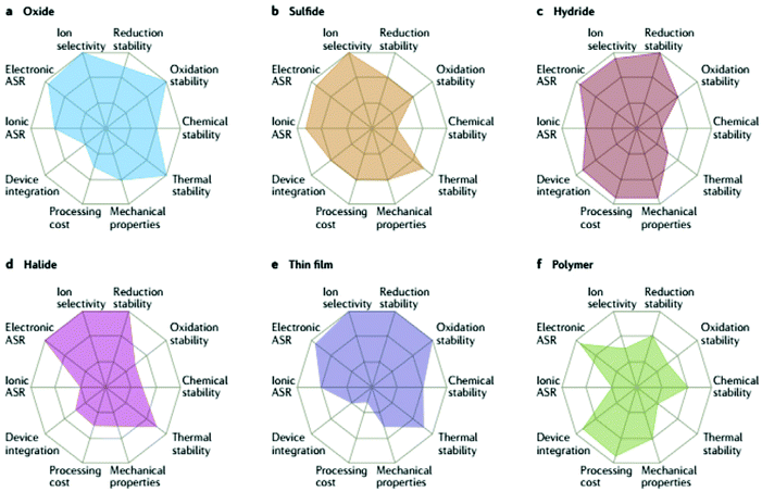 | ||
| Fig. 1 Performance of different solid electrolyte materials. Radar plots of the performance properties of oxide solid electrolytes (a), sulfide solid electrolytes (b), hydride solid electrolytes (c), halide solid electrolytes (d), thin-film electrolytes (e) and polymer solid electrolytes (f).13 Reproduced with permission from ref. 13. Copyright (2017), Springer Nature. | ||
One way to achieve better performance ISE is by tuning the structures of already known ISEs with cationic/anionic substitutions. Some of these structures are oxides such as perovskite, argyrodite, Li superionic conductor LISICON-type, Na superionic conductor NASICON-type, anti-perovskite or sulfides such as Thio-LISICON, and Li10GeP2S12 (LGPS) like structures. Such substitutions can enhance the bulk ionic conductivity by increasing the number of mobile Li ions9 and tuning the potential energy landscape of Li ions. There is a long list of mechanisms involved in conductivity enhancement by substitution including inducing Li sublattice disorder,10 lowering bottleneck energy,11 or lowering the phase transition temperature to a superionic conductor phase.9 Substitution can additionally influence the grain boundary conductivity and sinterability (densification) of the ISE.12 The effect of substitution is not limited to these properties and may often have unexpected detrimental impacts on other properties such as the electronic conductivity and electrochemical stability window of the ISE. It is therefore essential to do systematic and proper screening of multiple key ISE metrics in order to fully determine whether a substitution is beneficial or not. Understanding the exact mechanism of enhancement can give us hints for engineering better ISE such as multi-substitution.
In this review, we start by describing the different synthesis methods of ISE. We then consider in detail the experimental methods to be used to determine the key metrics needed to screen solid electrolytes. Finally, we survey the role that metal substitutions have played in the development of the various families of known ISE structures that are still being studied extensively for all-solid-state Li batteries. For each family, the influence of the substitutions on the different properties of the ISE and the underlying mechanisms are discussed. Additionally, the different substitution strategies used to optimize specific electrochemical properties are summarized.
2. Synthesis of solid electrolytes
ISEs are synthesized by various methods and can be made either into bulk powders or thin films. The methods used to make bulk powders include solid-state synthesis and wet-chemical methods such as co-precipitation, sol–gel, solvothermal, and hydrothermal. In the solid-state synthesis method, the reagents are ground together by ball milling or mortar and pestle and then pressed into green pellets for heat treatment. The drawback of the solid-state method is that high temperatures and long sintering times are required because the synthesis reactions happen at solid–solid interfaces, where energy is needed to overcome lattice energy and diffuse anions/cations.14 Usually intermediate grinding/repelleting is mandatory to form fresh interphases to yield pure phase materials. For instance, one calcination step is not enough to completely react all the raw materials in Al3+ substituted Li7La3Zr2O12 (LLZO) prepared by the solid-state method.15 Furthermore, it is not possible to produce a dense solid electrolyte using the solid-state method in a single heat step specially if non-oxide reactants are used such as carbonate based reagents, because cracks and voids form inside the bulk of the pellet during calcination; therefore, the calcined pellets must be re-ground and repressed into pellets for the sintering step. Thus, the calcination temperature and the property of the calcined powder formed after grinding influence the sintering temperature and the densification of the final ISE. For example, varying the calcination temperature of Al3+ substituted LiTi2(PO4)3 LTP electrolyte from 750 to 900 °C with the same sintering temperature increases the relative density of the final pellet from 85% to 98%.16 Sometimes, these solid mixtures are heated under a specific atmosphere; for example, heating the unsubstituted LLZO reagents mixture under CO2 can mitigate the lithium loss, thus stabilizing the cubic phase.17 On the other hand, if volatile or air-sensitive reagents such as sulfur are used, the mixing/pelletizing must be done in an argon-filled glovebox. The mixture can then be sealed in a tube usually made of quartz for the heat treatment. A carbon-coated tube is used to avoid contamination from the tube, or the samples are placed in a carbon crucible.The alternative methods to solid-state synthesis are all solution based. In the co-precipitation method, reagents are dissolved into aqueous solutions mixed and then a precipitating agent is added such as ammonium hydroxide. After filtering the precipitate, it is dried, preheated, and then pressed into pellets. The co-precipitation is less time consuming than the other methods. However, the drawback is that all the cations should be soluble in the aqueous mixture and do not precipitate before adding the precipitator. The sol–gel method by contrast proves to be far more versatile. The main types of sol–gel synthesis are the citrate (Pechini method) and polymerization. The citrate method involves adding citrate as a chelating agent to an aqueous solution containing the reactants. Once the solvent volume starts to reduce, a gel forms and total removal produces solid powder which then goes through the same high temperature heat treatment as the methods mentioned above. The formation of citrate complexes facilitates atomic scale mixing of the cations thus achieving a high homogeneity compared to solid-state synthesis. While the polymerization involves the hydrolysis of alkoxide reagents followed by the condensation forming a gel that is then dried, calcined, and pressed into pellets. The sol–gel method yields small size powders lowering the sintering temperature compared to the solid-state method.
In the synthesis approaches mentioned above, the last step is the sintering and many techniques have been successfully used to perform the sintering, such as furnace heating, floating zone (single crystal),18 spark plasma,19 and microwave assisted.20 The advantage of spark plasma and microwave assisted sintering over furnace heating is that less high temperature dwell time is needed to yield a dense ISE but with less grain size growth.21 Some synthesis methods used for a specific family of materials such as the melt-quench method for the glass-ceramic type solid electrolytes do not need a sintering step where the sample is heated until melt and then quenched to form glass after it is annealed to crystalize it into glass-ceramic material.22 The sintering process can be done under a specific atmosphere for instant O2-assisted sintering of a particular garnet solid electrolyte increased its relative density from 95% to 97% compared to the sintering conducted under the same conditions but in air.23 Usually, the sintering step requires high temperatures (as high as 1400 °C is not uncommon for ceramic oxides for example) where Li volatilization from the sample and contaminants diffusing from the substrate become critical issues to be mindful of. For example, during the sintering of Li3xLa(2/3)−xTiO3 (LLTO) at 1250 °C for 5 h the Li content drops from 0.5 to 0.3 per formula unit.24 Another concern is side reactions with the substrate. For example, sintering LLZO pellet at 1220 °C for 12 h in an alumina crucible causes the side in contact with the alumina to have a 16 at% unintentional Al content.25 At high temperatures, total prevention of lithium loss is not possible; thus, an excess amount of lithium (10%) is often added to the starting stoichiometry. The contamination from the substrate occurs typically with alumina substrates and can be avoided by using platinum or zirconia substrates or by using a sacrificial powder.25,26 The sacrificial powder approach involves covering the sample pellet with powder made of the same composition as the sample (it also sits on a bed of this powder). This sacrificial powder will then interact with the substrate (preventing sample/substrate contact) and lose more Li than the sample, thereby yielding a pellet with the desired composition and no contaminant. The composition of the prepared ISE must then be confirmed by elemental analysis, such as inductively coupled plasma (ICP).
The synthesis methods of ISE mentioned above are used to prepare thick electrolytes (pellets) typically used for screening of electrolytes for bulk-type all-solid-state batteries. However, when making full solid batteries it is advantageous to make this layer as thin as possible to maximize energy density, and a few such cases will be discussed herein. Numerous thin-film ISE deposition techniques have been utilized to make full solid batteries. These are divided into two categories: chemical vapor deposition (CVD) (e.g. atomic layer deposition ALD27,28) and physical vapor deposition (e.g. pulse laser deposition PLD).29 CVD is quite common due to the versatility of this method. In CVD, the film is formed through the reaction of the gaseous reactants. This reaction can be driven by (1) increasing the diffusion of the gaseous reactants via reducing the pressure (low-pressure CVD),30 (2) plasma (plasma enhanced CVD),31 (3) the heat induced by laser (laser CVD).32,33 The other more frequently used CVD method is the metalorganic chemical vapor deposition (MOCVD) in which organometallic (metal alkyl) reagents are used.34 The choice of specific CVD technique depends on the nature of the materials and the required thickness and adhesion. An advantage of these deposition techniques is that it allows to the construction of complicated 3D hierarchical designs. The other common method used to form a thin layer ISE is by spin coating the precursors (sol–gel) and then heat treating.35 Other than thin film and bulk forms of ISE, nanostructured ISE such as nanowires and nanoparticles are being explored. These nanowires can be fabricated by electrospinning.36 The nanostructured ISE have been used in a polymer–ISE composite electrolyte where the ISE can act as an ionic channel and a filler lowering polymer glass transition temperature, thus enhancing the overall room temperature conductivity.37 However, typically, most of the ISE screening is done on bulk pellets and will therefore be the primary focus of this review.
3. Screening methods for solid electrolytes
The continued improvement of the performance of ISE is essential for developing an ASSLB functioning at room temperature and out-classing the established Li-ion batteries. The inorganic solid electrolyte in ASSLB contributes to the total internal ionic resistance by the conductivity of its bulk, grain boundaries, and the electrolyte/electrode interfaces. There are several key properties that ISE must fulfill, the most fundamental of which are: high ionic conductivity, low electronic conductivity, and high stability with the electrodes under operating conditions. This section discusses the various methods used to determine these properties and presents some methods used to further understand the diffusion mechanisms at play.3.1 Ionic conductivity
Firstly, an ISE should be a good ionic conductor (>10−4 S cm−1) at room temperature and an electronic insulator (<10−10 S cm−1). It should be noted that liquid electrolytes have ionic conductivities on the order of 10−2 S cm−1 and many researchers consider 10−3 S cm−1 to be the minimum ionic conductivity required of solid electrolytes to be truly competitive. Only the ion of interest (lithium here) should be mobile with a transport number close to one because any small electronic conductivity can cause dendrite nucleation from the bulk of the electrolyte, especially at high current densities (σelectronic > 10−10 S cm−1 at 1 mA cm−2).38 The total electrical (ionic + electronic) conductivity of ISE is measured using electrochemical impedance spectroscopy by scanning MHz to mHz frequency range and applying 10–100 mV potential after depositing electrical contacts on the two faces of a polished ISE pellet. This contact can be deposited by thermal evaporation, magnetron sputtering, e-beam evaporation, or applying a colloidal gold paste and then annealing it.39 Other contacts such as silver and platinum can also be used. The acquired impedance spectrum is usually represented by a Nyquist plot. A typical Nyquist plot of an ISE consists of high-frequency region semicircles and a low-frequency spike as shown in Fig. 2(a). The spectrum is fitted to an equivalent electronic circuit. The semicircles are modeled by a resistor and capacitor in parallel and the spike as a capacitor as shown in Fig. 2(a). The capacitor is usually replaced by a constant phase element to fit the non-ideal capacitance of the electrochemical system components. The low-frequency spike is assigned to the capacitance of the blocking electrode, while the semicircles are assigned to the bulk and grain boundary. The capacitance of the semicircles helps to differentiate between the bulk and grain boundary. A typical bulk and grain boundary capacitances are 10−12 F and 10−11–10−8 F respectively which are calculated from a standard permittivity of ∼10 using parallel plate capacitor equation.40 For instance, the grain boundary conductivity in LLTO is much lower than the bulk due to the orientation of the domains blocking lithium transport from one domain to the other.41 In contrast, in LLZO some researchers found grain boundary conductivity higher than the bulk.42 The bulk and grain boundary are not always resolved as two semicircles. However, sometimes only one semicircle is observed, and that is due to the property of the material or the frequency range used for the measurement. If only one semicircle is observed (total conductivity) with the other one out of the measurement frequency region, then measuring the impedance at low temperatures (−100 to −130 °C) can separate the bulk and grain boundary conductivities.43,44 Prior to studying the impact of substitutions, it is critical to correctly assign the contribution of the bulk and grain boundary to the total conductivity to understand the effect of specific substitutions.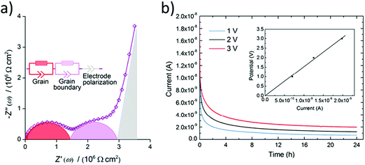 | ||
| Fig. 2 (a) Typical Nyquist plot for a ISE with a resolved bulk and grain boundary resistances fitted to an equivalent circuit.43 Reproduced with permission from ref. 43. Copyright (2016), Elsevier. (b) A chronoamperometry measurements at different applied potentials and the inset is a plot of the applied potential vs. the steady-state current such that the slope is used to calculate the electronic conductivity.68 Reproduced with permission from ref. 68. Copyright (2015), Elsevier. | ||
It is also important to recognize the usefulness of performing the conductivity measurements as a function of temperature. The key transitions required to enable conduction (e.g. lithium sublattice order–disorder, defects formation) can occur at various temperature regimes.45 For example exploring these transitions in intrinsic ion conductors which conductivity depends on the intrinsic defects that increase with temperature. Likewise studying the temperature dependent conduction mechanisms of extrinsic ion conductors which conductivity is due to substitution like doping in extrinsic semiconductor. Typically, such data is plotted as log(σT) vs. 1/T to investigate whether a specific ion conductor exhibits Arrhenius or non-Arrhenius type ion conduction. The activation energy and pre-exponential factor extracted from the Arrhenius plot are used for comparing performances and developing solid electrolyte by helping to understand the underlying mechanisms causing the conduction differences. This is especially useful when conductivities are so small that they cannot be measured at room temperature. In such cases, the impact of substitutions represents important information to develop the electrolyte but cannot be observed unless impedance measurements are performed at higher temperatures, and conductivities can then be extrapolated to room temperature. Next, the total ionic conductivity is calculated by measuring the electronic conductivity and subtracting it from the total electrical conductivity.
3.2 Electronic conductivity
The Hebb–Wagner method is used to measure the electronic conductivity by applying DC polarization on an asymmetric (−)Li/SSE/Cu(+) cell with a reversible and an irreversible (ion blocking) electrode such as lithium and copper respectively.46,47 The electronic conductivity is calculated from the voltage vs. steady-state current plot of the chronoamperometry measurements at different voltages as shown in Fig. 2(b). The lithium transference number can then be calculated from the ionic contribution to the DC total conductivity obtained at t = 0 s prior to steady-state or total conductivity from the electrochemical impedance spectroscopy (EIS) measurement. In case the investigated ISE is not stable against lithium electrode the upper limit of electronic conductivity can be measured using two blocking electrodes instead.38 Thus, it is important for comparing the electronic conductivity to have similar cell configuration moreover the same applied potential because for some ISEs the electronic conductivity is not ohmic at all applied potentials.48 Electronic conductivity below 10−10 S cm−1 is needed for dendrite free ASSLB operating at 1 mA cm−2.383.3 Electrochemical stability at the anode
Besides appropriate conductivities, solid electrolytes require a wide electrochemical stability window. Alternatively, they may form a stable ionically conductive solid electrolyte interphase (SEI) with the electrode. The stability against the anode is often done vs. lithium as this is considered to be key in order for solid batteries to out-perform Li-ion batteries in terms of energy density. The instability against lithium metal is due to the lithium insertion reaction forming a reduced decomposition phase as shown in Fig. 3(b). Stability against lithium electrode is best probed by measuring the impedance (using EIS) of a Li/ISE/Li symmetric cell at different time intervals during electrochemical cycling. Fig. 4 shows the interfacial resistance between Nb5+ substituted LLZO and metal electrode increases by time, indicating the formation of an electronic conductive phase propagating through the bulk of the electrolyte.49 The same symmetric cell is also used to study the interfacial resistance between the lithium electrode and the ISE conditioned (sanding dry/wet,50 acid etching,51 applying a coating52) surface signifying lithium wettability. Furthermore, the galvanostatic cycling (plating/stripping) of this symmetric cell at different current densities can demonstrate in progressive cycles if any dendrites will form causing shortage or if the internal resistance will continuously increase (measured voltage at same current density increase by each cycle), which could be due to bad electrode/electrolyte contact or electrolyte decomposition into ion resistive phase.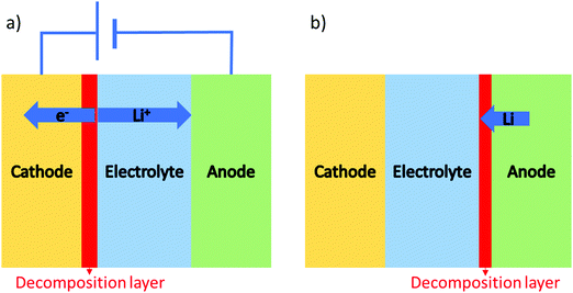 | ||
| Fig. 3 Two possible interface reactions: (a) lithium extraction in a closed circuit system, (b) lithium insertion that can occur in both open and close circuits. | ||
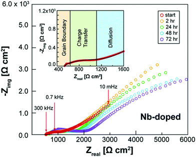 | ||
| Fig. 4 EIS spectra of Li/Nb-LLZO/Li symmetric cell showing the change in impedance over a 72 h period due to the electrolyte reacting with the Li metal electrodes.49 Reproduced with permission from ref. 49. Copyright (2019), John Wiley and Sons. | ||
3.4 Electrochemical stability with the cathode
The upper limit of the electrochemical stability window is the tendency for lithium extraction forming a lithium deficient oxidized interphase, as shown in Fig. 3(a). This limit has been explored in the literature using a variety of methods. The most common is to use a Li/ISE/Au cell using cyclic voltammetry, as illustrated in Fig. 5(a). However, this method has been shown to systematically overestimate the electrochemical stability window due to the limited electrical contact between the current collector and the ISE (i.e. the poor electronic conductivity of the ISE prevents the reactions that would otherwise take place at the high potentials).53 The alternative method that should be used is to make a Li/TE/ISE+CA/Au (where TE is a functional electrolyte, ISE is the electrolyte under investigation and CA is a conductive additive). The CA is used to increase the amount of electronic paths such that poor electronic conductivity does not prevent the parasitic reactions from taking place. The test electrolyte (TE) can either be a liquid organic electrolyte54 or the ISE under investigation as long as its ionic conductivity is adequate. This technique systematically shows a more representative narrower electrochemical stability window which also fits better the computational predictions. For example, the cyclic voltammetry of Li10GeP2S12 (LGPS) with added Pt black shows a lower oxidation limit of 2.5 V compared to stability up to 4 V as determined by the Li/ISE/Au CV method as shown in Fig. 5.53 No stabilities determined by the Li/ISE/Au CV method will be reported in this review article as they are deemed inaccurate. It is worth to mention that electrochemical stability window is also investigated computationally using different approaches such as calculating the electronic bandgap and band position which only assumes electron transfer. The other two methods, the stoichiometry stability method and phase stability method, present the process of stability against the electrodes (lithium extraction/insertion) as shown in Fig. 3 more accurately by including the chemical potential of the lithium which contains the potentials of the electrodes.55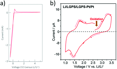 | ||
| Fig. 5 Cyclic voltammetry of Li/LGPS/Au and Li/LGPS/LGPS-Pt/Pt to investigate the decomposition at high potentials.53,69 Reproduced with permission from ref. 69. Copyright (2011), Springer Nature. Reproduced with permission from ref. 53. Copyright (2016), John Wiley and Sons. The CV demonstrates stability up to the maximum potential tested (4.5 V), while testing the LGPS as a cathode with conductive additive shows oxidation at a potential of 2.5 V, consistent with computational studies. | ||
Finally, the solid electrolyte should have optimal mechanical properties; for instance, it should be soft and deformable to wet the electrode better and be able to accommodate the volume expansion of the electrode; otherwise, if brittle, it cracks, but at the same time, it should have enough hardness to prevent the dendrite growth. Although the mechanical properties and thermal stability of great importance for the ISE performance, will not be discussed in this review.
3.5 Characterization of structures and mechanism determination
The structure is most commonly identified by powder X-ray diffraction. In a new crystal structure, synchrotron X-ray diffraction or neutron diffraction is required to resolve the new structure. The mechanism underlying lithium transport is predicted by conducting neutron diffraction and relaxation nuclear magnetic resonance at different temperatures to locate the exact positions of the lithium ion and reveal their local dynamics. Moreover, from the neutron diffraction data, the Maximum Entropy Method (MEM) gives information about the Li+ diffusion pathways as shown in Fig. 6(b).56 MEM is complemented with the Bond Valence (BV) method that can provide the path that minimizes the empirically determined valence mismatch for lithium ion diffusion. BV calculations are extremely easy/cheap to perform and yield iso-valence mismatch surface maps as shown in Fig. 6(a). From BV calculations, the bond valence landscape (BVL) can be extracted which shows the relative energy of the barriers that can then be compared to the energy barriers calculated from computational simulation and from the lithium nuclear densities. Moreover, molecular dynamic calculations are utilized to predict the possible mechanisms and pathways of lithium diffusion.57 All these techniques are complemented with each other to produce a more accurate description of lithium migration.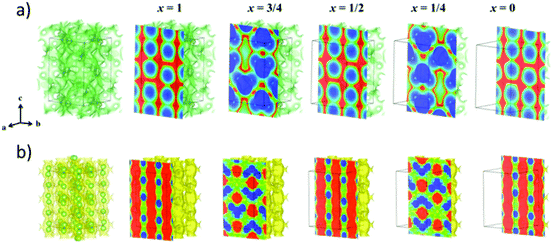 | ||
| Fig. 6 (a) Bond valence (BV) map of LGPS with energy threshold of ΔV = 0.10 v.u. (b) The lithium nuclear density map reconstructed by maximum entropy method (MEM).56 Reproduced with permission from ref. 56. Copyright (2016), American Chemical Society. | ||
3.6 Impact of substitutions on solid electrolyte metrics
A great number of different substitutions into ISEs have been performed over the years. These have been done for a variety of reasons, we discuss the main driving forces for substitutions into ISEs in this section. First and foremost, substitutions are performed to improve the bulk ionic conductivity of the ceramic structure. The bulk ionic conductivity is governed by the composition and crystal structure of the host framework, which determines the potential surface landscape of the lithium diffusion pathway. The pathways typically include at least one bottleneck through which the lithium ion diffusion is limited. The energy barrier of the bottleneck can be lowered by introducing larger ionic radius cations on neighboring sites in order to increase the lattice size and thereby enlarge the bottleneck making more room for Li to pass through.58 On the other hand, inducing lithium sublattice disorder (partially occupied sites) makes the lithium sites energetically equivalent reducing the defect formation energy contribution to the activation energy. Therefore, different lithium and vacancy distribution control the number of mobile charge carriers leading to higher or lower conductivity.Substitutions can therefore impact the bulk conductivity via a wide variety of mechanisms. We discuss these in detail in later sections focusing on each class of electrolyte, but it is worth illustrating a few such mechanisms here as they do occur regardless of the electrolyte class. For example, the creation or destruction of vacancies on the lithium site is a common means to tune conductivity. This is well illustrated in stoichiometric tetragonal LLZO garnet where lithium ions fully occupy the lowest energy tetragonal site making the diffusion of lithium ions very difficult but introducing vacancies, for instance, by super-valent substitution such as the partial substitution of Li+ by Ga3+ perturbs the lithium distribution and makes diffusion more facile.59 The result is two partially occupied tetrahedral and octahedral sites, which increase the conductivity by three orders of magnitude.60 Another common approach to tune conductivity is to make sub-valent substitution in order to add interstitials to the structure to create local distortion and flatten the energy landscape of the lithium pathway.61
Substitutions are also often made in an attempt to improve the grain boundary ionic conductivity. In cases where the grain boundary conductivity is low, tuning the microstructure becomes essential. It is also important to recognize that the presence of a secondary phase at the grain boundaries also contributes to the total ionic conductivity (either positively or negatively depending on this phases impact on sintering properties).62 The presence of voids between the grains drastically lowers the ionic conductivity; hence measuring the relative density of the materials is crucial for comparing the performance of ionic conductors.63 The relative density of ISE also in great measure dictates its resistance against dendrite penetration at high current densities.64 The relative density/porosity changes by the synthesis method, sintering method/temperatures/time, and introduction of substitutions.
Substitutions into the solid electrolyte is also often used as a means to tune the interfacial area-specific resistance (ASR) with the electrodes that include wettability and interphase stability. For example, fluorination of LLZO facilitates homogenous lithium plating and stripping cycles at different current densities as shown in Fig. 7.65 It should be mentioned that substitutions into the bulk of the material in order to impact the surface resistance may have detrimental impacts on the bulk properties. Often times, this approach is in competition with the use of a buffer layer (i.e. a thin layer of a different solid electrolyte at the surface of the cathode/anode). For example, coating lithium cathode with lithium niobate66 and coating the anode with alumina layer67 can mitigate the electrolyte/electrode instability hence keeping the interfacial impedance low.
 | ||
| Fig. 7 Galvanostatic Li plating/stripping in the Li|LGLZO|Li and the Li|F-LGLZO|Li cells.65 Reproduced with permission from ref. 65. Copyright (2019), American Chemical Society. | ||
4. Impact of substitutions into specific classes of ISE
4.1 Garnets
![[3 with combining macron]](https://www.rsc.org/images/entities/char_0033_0304.gif) d space group structure. A2+ occupies the dodecahedral sites and B3+ octahedral sites, while Si4+ occupies the tetrahedral sites. However, the ionic conductivity of garnets is poor until the Si is replaced by Li+, and the lithium content can be further increased by replacing A2+ and B3+ with cations of different oxidation states forming lithium stuffed garnets. Lithium lanthanum zirconate (LLZO) is the most promising in the lithium-stuffed garnet-type solid electrolytes. LLZO has the basis chemical formula Li7La3Zr2O12 but further substitutions must be made to make this a viable solid electrolyte. LLZO has two polymorphs: tetragonal (t-LLZO, I41/acd space group) and cubic (c-LLZO, Ia
d space group structure. A2+ occupies the dodecahedral sites and B3+ octahedral sites, while Si4+ occupies the tetrahedral sites. However, the ionic conductivity of garnets is poor until the Si is replaced by Li+, and the lithium content can be further increased by replacing A2+ and B3+ with cations of different oxidation states forming lithium stuffed garnets. Lithium lanthanum zirconate (LLZO) is the most promising in the lithium-stuffed garnet-type solid electrolytes. LLZO has the basis chemical formula Li7La3Zr2O12 but further substitutions must be made to make this a viable solid electrolyte. LLZO has two polymorphs: tetragonal (t-LLZO, I41/acd space group) and cubic (c-LLZO, Ia![[3 with combining macron]](https://www.rsc.org/images/entities/char_0033_0304.gif) d space group). The host framework of t-LLZO as shown in Fig. 8(a) consists of La3+ at two dodecahedral 8b and 16e sites and Zr4+ at octahedral 16c site. The LaO8 and ZrO6 polyhedra are connected by edge-sharing while the lithium ions are ordered by fully occupying tetrahedral 8a site and two distorted octahedral 16f and 32g sites. The host framework of c-LLZO shown in Fig. 8(c) consists of La3+ at the dodecahedral 24c sites and Zr4+ at octahedral 16a sites. The LaO8 and ZrO6 polyhedra are connected by edge-sharing while the framework interstitial space is accommodated by the lithium ions and vacancies. In the c-LLZO the lithium ions only partially occupy tetragonal 24d sites and distorted octahedral 96h site as shown in Fig. 8(c). The LiO4 tetrahedra of c-LLZO shares face with the LiO6 distorted octahedra through which lithium ions hope (this is the bottleneck). c-LLZO has higher conductivity than t-LLZO thus, stabilizing the cubic phase is a strategy used to enhance conductivity. LLZO has a good electrochemical stability window. Its stability against the lithium anode is due to the formation of a solid electrolyte interphase (SEI), which increases the interfacial resistance slightly but also passivates the electrolyte decomposition.49 A disadvantage of the LLZO is its air sensitivity which forms Li2CO3 increasing the interfacial resistance against the electrodes.70
d space group). The host framework of t-LLZO as shown in Fig. 8(a) consists of La3+ at two dodecahedral 8b and 16e sites and Zr4+ at octahedral 16c site. The LaO8 and ZrO6 polyhedra are connected by edge-sharing while the lithium ions are ordered by fully occupying tetrahedral 8a site and two distorted octahedral 16f and 32g sites. The host framework of c-LLZO shown in Fig. 8(c) consists of La3+ at the dodecahedral 24c sites and Zr4+ at octahedral 16a sites. The LaO8 and ZrO6 polyhedra are connected by edge-sharing while the framework interstitial space is accommodated by the lithium ions and vacancies. In the c-LLZO the lithium ions only partially occupy tetragonal 24d sites and distorted octahedral 96h site as shown in Fig. 8(c). The LiO4 tetrahedra of c-LLZO shares face with the LiO6 distorted octahedra through which lithium ions hope (this is the bottleneck). c-LLZO has higher conductivity than t-LLZO thus, stabilizing the cubic phase is a strategy used to enhance conductivity. LLZO has a good electrochemical stability window. Its stability against the lithium anode is due to the formation of a solid electrolyte interphase (SEI), which increases the interfacial resistance slightly but also passivates the electrolyte decomposition.49 A disadvantage of the LLZO is its air sensitivity which forms Li2CO3 increasing the interfacial resistance against the electrodes.70
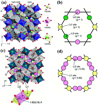 | ||
| Fig. 8 Crystal structure of t-LLZO and lithium sites occupancy (a)102 Reproduced with permission from ref. 102. Copyright (2009), Elsevier. (b), Crystal structure of c-LLZO and lithium sites occupancy (c and d).103 Reproduced with permission from ref. 103. Copyright (2011), The Chemical Society of Japan. | ||
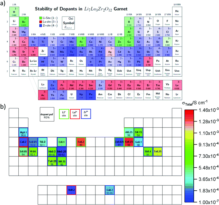 | ||
| Fig. 9 (a) Computational results for the possible substitutions on various sites in garnet LLZO and their defect formation energies.104 Reproduced with permission from ref. 104. Copyright (2015), American Chemical Society. (b) Experimental single substitutions of the different LLZO crystal sites (Li, La, Zr) with their corresponding total ionic conductivity (color map), and relative density (RD%).59,63,81,99,105–118 | ||
| Composition | Synthesis method | σ Total (S cm−1) | E a (eV) | σ electronic (S cm−1) | ρ/ρo (%) | Cathode | Capacity (mA h g−1) | V ave (V) | Ref. |
|---|---|---|---|---|---|---|---|---|---|
| a This is the only study where a Li/Li symmetric cell was used to test stability vs. Li metal. They obtained 0.5 mA cm−2/25 Ω cm2. | |||||||||
| Li6.5Ga0.2La2.9Sr0.1Zr2O12 | Solid state | 5.50 × 10⁻⁴ | 0.31 | 1.43 × 10⁻⁷ | — | — | — | — | 119 |
| Li6.66La2.94Sr0.06Zr1.6Sb0.4O12 | Solid state | 8.83 × 10⁻⁴ | 0.26 | — | 95.1 | LFP | 157 | 3.75 | 120 |
| Li6.775Al0.05La3Zr1.925Sb0.075O12 | Solid state | 4.10 × 10⁻⁴ | 0.32 | — | 96.7 | — | — | — | 121 |
| Li6.375Al0.075La3Zr1.8Mo0.2O12 | Sol–gel | 4.41 × 10⁻⁴ | 0.30 | 1.00 × 10⁻⁸ | 96.4 | — | — | — | 122 |
| Li7La3ZrNb0.5Y0.5O12 | Solid state | 8.29 × 10⁻⁴ | 0.31 | — | 90.7 | LFP | 140 | 3.53 | 123 |
| Li6.45Ca0.05La2.95Ta0.6Zr1.4O12 | Solution | 4.03 × 10⁻⁴ | - | — | — | S | 1090 | 2.1 | 124 |
| Li6.65Ga0.15La3Zr1.90Sc0.10O12 | Sol–gel | 1.80 × 10⁻³ | 0.29 | — | 93 | — | — | — | 83 |
| Al–Li6.75La3Zr1.75Ta0.25O12 | Solid state | 9.28 × 10⁻⁴ | 0.32 | — | 94.1 | — | — | — | 125 |
| Li6.945La2.98Ba0.02Zr1.925Sb0.075O12 | Solid state | 1.53 × 10⁻⁴ | 0.25 | 9.47 × 10⁻⁷ | 95 | — | — | — | 126 |
| Li6.5La3Hf1.5Ta0.5O12 | Solid state | 3.45 × 10⁻⁴ | 0.44 | — | 93.2 | — | — | — | 127 |
| Li6.15La3Zr1.75Ta0.25Al0.2O12 | Co-prec. | 3.70 × 10⁻⁴ | 0.30 | — | 98 | — | — | — | 81 |
| Li6.15La3Zr1.75Ta0.25Ga0.2O12 | Co-prec. | 4.10 × 10⁻⁴ | 0.27 | — | 98 | — | — | — | 81 |
| Li7La3Zr2O12 (1.7 w%Al 0.1%Si) | Solid state | 6.80 × 10⁻⁴ | — | — | — | — | — | — | 128 |
| Li6.8La2.95Ba0.05Zr1.75Ta0.25O12 | Solid state | 6.50 × 10⁻⁴ | 0.29 | — | 99.7 | — | — | — | 85 |
| Li6.4Ga0.1La3Zr1.55Ba0.05Ta0.4O12a | Solid state | 1.02 × 10⁻³ | 0.40 | — | — | — | — | — | 129 |
| Li6.65Ga0.05La2.95Ba0.05Zr1.75Ta0.25O12 | Solid state | 7.20 × 10⁻⁴ | 0.28 | — | 99.9 | LFP | 146.8 | 3.29 | 85 |
| Li6.52La2.98Ba0.02Zr1.9Y0.1Al0.2O12 | Solid state | 2.02 × 10⁻⁴ | — | — | 93.23 | — | — | — | 130 |
| Li5.72La2.98Ba0.02Zr1.65W0.35Al0.2O12 | Solid state | 6.35 × 10⁻⁴ | — | — | 96.32 | — | — | — | 130 |
| Composition | ρ/ρo (%) | σ Total (S cm−1) | E a (eV) | σ electronic (S cm−1) | Cell configuration | DC voltage applied (V) | Ref. |
|---|---|---|---|---|---|---|---|
| Li6.24Al0.24La3Zr2O11.98 | 98 | 4.00 × 10⁻⁴ | 0.26 | 2.00 × 10⁻⁸ | Au/ISE/Au | — | 107 |
| LLZO 0.9%Al | — | 4.00 × 10⁻⁴ | 0.34 | <5 × 10⁻¹¹ | Li/ISE/Au | 2.5–4.5 | 131 |
| Li6.4Ga0.2La3Zr2O12 | — | 1.00 × 10⁻³ | 0.30 | 5.00 × 10⁻¹⁰ | Au/ISE/Au | 0.01–0.3 | 86 |
| Li6.4Ga0.2La3Zr2O12 | 97 | 1.38 × 10⁻³ | 0.30 | 4.33 × 10⁻⁸ | Au/ISE/Au | 2 | 132 |
| Li6.25Ga0.25La3Zr2O12 | 94 | 1.46 × 10⁻³ | 0.25 | 5.40 × 10⁻⁸ | Ag/ISE/Ag | 0.1 | 59 |
| Li6.25Ga0.25La3Zr2O12 | 91 | 3.50 × 10⁻⁴ | 7.10 × 10⁻⁸ | Au/ISE/Au | — | 133 | |
| LLZO 1.7% Sr | 94 | 5.00 × 10⁻⁴ | 0.31 | 1.00 × 10⁻⁸ | Au/ISE/Au | 0.1 | 109 |
| Li6.75La3Zr1.75Ta0.25O12 | 96 | 7.40 × 10⁻⁴ | 0.33 | 2.10 × 10⁻⁷ | Au/ISE/Au | 5 | 134 |
| Li6.75La3Zr1.75Ta0.25O12 | 97 | 6.40 × 10⁻⁴ | 0.30 | 5.30 × 10⁻⁷ | Au/ISE/Au | 5 | 135 |
| Li6.7La3Zr1.7Ta0.3O12 | 92 | 1.03 × 10⁻⁴ | 0.37 | 5.40 × 10⁻⁹ | Ag/ISE/Ag | 0.1 | 136 |
| Li6.4La3Zr1.4Ta0.6O12 | — | 1.01 × 10⁻³ | — | <3 × 10⁻¹¹ | Li/ISE/Au | 2.5–4.5 | 48 |
| Li6.30La3Zr1.65W0.35O12 | 96 | 6.60 × 10⁻⁴ | 0.42 | 1.90 × 10⁻⁸ | — | 4 | 63 |
| Li7La2.75Ca0.25Zr1.75Nb0.25O12 | — | 1.25 × 10⁻⁴ | 3.59 × 10⁻⁸ | Au/ISE/Au | 0.7 | 87 | |
| Li7La2.75Ca0.25Zr1.75Nb0.25O12@LiAlO2 | — | 1.23 × 10⁻⁴ | 1.01 × 10⁻⁸ | Au/ISE/Au | 0.7 | 87 | |
| Li6.5Ga0.2La2.9Sr0.1Zr2O12 | — | 5.50 × 10⁻⁴ | 0.31 | 1.43 × 10⁻⁷ | Ag/ISE/Ag | 1 | 119 |
| Li6.375Al0.075La3Zr1.8Mo0.2O12 | 96 | 4.41 × 10⁻⁴ | 0.30 | 1.00 × 10⁻⁸ | Ag/ISE/Ag | 0.1 | 122 |
| Li6.4La3Zr1.4Ta0.6O12 6% MgO | 95 | 3.58 × 10⁻⁴ | 0.42 | 1.59 × 10⁻⁷ | Au/ISE/Au | 4 | 137 |
| Li5.9Al0.2La3Zr1.75W0.25O12 | 94 | 4.90 × 10⁻⁴ | 3.70 × 10⁻⁹ | Ag/ISE/Ag | 0.1 | 138 | |
| Li6.905La2.98Ba0.02Zr1.925Sb0.075O12 | 95 | 1.53 × 10⁻⁴ | 0.25 | 9.47 × 10⁻⁷ | Ag/ISE/Ag | — | 126 |
| Li6.7La3Zr1.5Nb0.4Sm0.1O12 | 94 | 1.06 × 10⁻³ | 0.39 | 8.60 × 10⁻¹⁰ | Ag/ISE/Ag | 0.1 | 139 |
Partial substitution of the Li in LLZO can stabilize the c-LLZO, such substitutions include Al3+, Ga3+, Zn2+, Fe3+ and these result in enhanced ionic conductivities as shown in Fig. 9(b). At high sintering temperatures, unintentional Al3+ substitution from alumina substrate can occur. Al-LLZO has been reported with ionic conductivities as high as 3.1 × 10⁻⁴ S cm−1 at its solubility limit of x = 0.25 in Li7−3xAlxLa3Zr2O12 whereas the ionic conductivity of unsubstituted LLZO is 2.0 × 10⁻⁷ S cm−1.72 Gallium substitution also stabilizes the c-LLZO by substituting at the 24d tetrahedral lithium site and producing vacancies to preserve charge neutrality. As the Ga3+ content increases in Li7−xGaxLa3Zr2O12 the lattice size and bottleneck size do not change; however, due to the Li–Ga coulombic repulsion, the vacancies around Ga3+ occupied sites are inaccessible (trapped), causing the lithium conductivity to decrease in the range 0 ≤ x ≤ 0.10. On the other hand, for 0.10 < x ≤ 0.30, the conductivity decrease trend becomes relatively flat because the extra vacancies confine percolation pathways for lithium ions motion as shown in Fig. 10.73 In Li7−3xGaxLa3Zr2O12, the highest conductivity of 1.46 × 10⁻³ S cm−1 is achieved at x = 0.25.59 Some reports show that Ga occupies the 96h site and stabilizes the c-LLZO with I![[4 with combining macron]](https://www.rsc.org/images/entities/char_0034_0304.gif)
![[3 with combining macron]](https://www.rsc.org/images/entities/char_0033_0304.gif) d space group. Accordingly, the reason the higher ionic conductivity of Ga-LLZO compared to Al-LLZO is due to the different site occupation where 96h site occupation does not block lithium long range path as it does the 24d site.74 Compared to Ga3+ substitution Zn2+ likewise stabilizes the cubic phase. In both systems, part of the compensating vacancies are added to the tetragonal site while the rest added to the octahedral site. The amount of vacancies created by Zn2+ is not enough to introduce vacancies to a non-vicinal octahedral site as in Ga-LLZO to facilitate lithium mobility leading to more than an order of magnitude lower conductivity. The negative aspect of Li site substitution is that it hinders the lithium path while deactivating the nearest neighboring octahedral site vacancies forming defect clusters; thus, high content of substituent at this site can block the lithium path.75
d space group. Accordingly, the reason the higher ionic conductivity of Ga-LLZO compared to Al-LLZO is due to the different site occupation where 96h site occupation does not block lithium long range path as it does the 24d site.74 Compared to Ga3+ substitution Zn2+ likewise stabilizes the cubic phase. In both systems, part of the compensating vacancies are added to the tetragonal site while the rest added to the octahedral site. The amount of vacancies created by Zn2+ is not enough to introduce vacancies to a non-vicinal octahedral site as in Ga-LLZO to facilitate lithium mobility leading to more than an order of magnitude lower conductivity. The negative aspect of Li site substitution is that it hinders the lithium path while deactivating the nearest neighboring octahedral site vacancies forming defect clusters; thus, high content of substituent at this site can block the lithium path.75
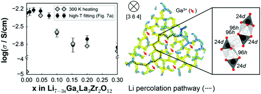 | ||
| Fig. 10 The effect of different content of Ga substitution in LLZO on ionic conductivity and the lithium percolation path.73 Reproduced with permission from ref. 73. Copyright (2015), American Chemical Society. | ||
Some substituents have a dual role of stabilizing c-LLZO and enhancing sinterability. For instance, the lower sintering temperature of 1000 °C for Ga-LLZO vs. 1100 °C for Al-LZZO and the associate higher densification of the Ga-LLZO are both attributed to the low eutectic point of Li–Ga–O compounds which is present as a liquid phase at the grain-boundaries during synthesis.76 Dense ISEs will have enhanced ionic conductivity and they also help impede dendrite formation. Fe3+ substituted LLZO has high ionic conductivity, but it is unstable against the lithium anode because it gets reduced to Fe2+ yielding an electronically conductive phase that propagates through the bulk and creates a short circuit.77 This again illustrates the critical importance of screening all key metrics in substitution studies of solid electrolytes.
Partial substitution of Zr4+ site similarly stabilizes c-LLZO, and its advantage over Li site substitution is that it does not hinder the lithium paths. Such substitutions include Ge4+, Nb5+, Ta5+, Sc3+. A small amount of alkaline earth metal substitution around 0.05 likewise substitutes the Zr4+ site. It expands the lattice size because alkaline earth metals have larger ionic radii than Zr, which causes the bottleneck size to increase, thus lowering the motional energy. Thus as shown in Fig. 11 larger the alkaline earth metal is higher ionic conductivity is attained.78 Alkaline earth metal substitution also improves the sinterability by its lower melting point compared to ZrO2.12 On the other hand large amount of alkaline earth metal substituents around 0.5 substitutes the La site.79 Ta5+ substitution of LLZO stabilizes the c-LLZO and at optimal lithium concentration of 0.6 per unit formula with the presence of a small amount of Al from the substrate distributed at the grain boundaries shows highest conductivity of 10−3 S cm−1.80 When Ta-LLZO is co-substituted with Ga or Al the conductivity decreases because they occupy Li sublattice hindering their diffusion.81
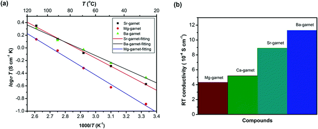 | ||
| Fig. 11 The conductivity of different alkaline earth substitution of LLZO.78 Reproduced with permission from ref. 78. Copyright (2016), John Wiley and Sons. | ||
Alkaline-earth elements substitution of LLZO with contents above 0.05 substitute the La3+ enhancing the sinterability. The density of alkaline earth element substituted LLZO increases with the ionic radius of the alkaline earth elements.
The interphase resistance of substituted LLZO with lithium anode depends on the nature of the substituents; for instance, in Al, Ta, Nb substituted LLZO, when in contact with lithium metal, Zr is reduced forming an oxygen deficient layer increasing the interfacial resistance. The amount of oxygen deficient layer forms in the substituted LLZO is as follows Ta4+ < Nb5+ < Al3+. This interphase was explored by measuring the change in interfacial impedance of Li/substituted-LLZO/Li at different time intervals and complemented by XPS measurement to explore the reduced species. Although in Nb-LLZO similar amount of oxygen deficient interphase forms but its reduction leads to the formation of a conductive phase that propagates through the bulk of ISE. While in Al substituted LLZO Zr4+ reduces into protecting oxygen deficient layer.49 The lithium stability of the high ionic conductive Nb-LLZO is improved by co-substituting with Ga.82 Multiple substitutions further improves the ionic conductivity as shown in Table 1, such as substituting Li+ by Ga3+ to stabilize the cubic phase and Zr4+ by Sc3+ to increase the number of lithium ions and improve the density. Additionally, Sc3+ causes local disorder of the Li network, enhancing the local mobility.83 Multi-substitution schemes are also employed, such as Li6.65Ga0.05La2.95Ba0.05Zr1.75Ta0.25O12 that includes supervalent substitution of Li+ and Zr4+ by Ga4+ and Ta5+ respectively and this stabilizes the c-LLZO by introducing vacancies besides Ga4+ has a role of enhancing the sinterability.84 Simultaneously, subvalent substitution La3+ by Ba2+ increases the lithium concentration and the bottleneck size due to its larger ionic radius. Additionally, multi-substituion decreases oxygen deficiency. These all enhance the lithium ion conductivity.85
The electronic conductivities of substituted LLZO are surveyed in Table 2. The electronic conductivity of single crystal Ga-LLZO is around 10−10 S cm−1 while for the polycrystalline material it is 10−8 S cm−1. The higher electronic conductivity in the polycrystalline sample is due the grain boundary and not of the intrinsic bulk, which implies that researchers must be mindful of the electronic conductivity in the final device and not solely in a perfect crystal.86 Further studies demonstrate that coating Ca-Nb-LLZO with LiAlO2 before sintering lowers the electronic conductivity from 3.59 to 1.01 × 10⁻⁸ S cm−1.87 This illustrates (as in part I of this review) that coatings can often be used to enhance surface properties without excess substitution into the bulk of the materials, such that coating methods are often in competition with bulk substitutions in real applications. An important current drawback of LLZO is that Li2CO3 forms when LLZO is exposed to air and this reduces the ionic conductivity.88
Though the focus of this review is the impact of substitutions, it is worth briefly summarizing here the state-of-the-art for each class of ISE in order to consider what future role substitutions may play. The interfacial resistance between the garnet electrolyte and the electrodes currently limits the performance of garnet based all-solid-state batteries. Different strategies have been used to reduce garnet/Li interface impedance. Some examples include using molten Li–C,89 coating garnet with C, surface acid treatment,51 wet sanding,50 thin layer of Ag, Sn or Ge,90–92 solid polymer electrolyte interface,93 and Al2O3 layer deposition.94 Similarly, the interfacial resistance between garnet and cathode is high because of the rigid nature of the garnet materials and the high cathode/garnet interfacial instability. One way to reduce the interfacial resistance is by co-sintering the composite cathode/electrolyte, but the electrolyte and electrode should not react at that temperature; otherwise, a more resistive interface can form. For instance, when Al-LLZO is co-sintered with LiCoO2 (LCO), a resistive interface forms due to Al diffusion at high temperature forming t-LLZO at the interface.95 This can be avoided by using Ta-LLZO instead. A discharge capacity of 110 mA h g−1 with 50 μA cm−2 current density at 50 °C was achieved in a LiCoO2/Ta-LLZO/Li cell configuration with a composite cathode composed of LiCoO2 and Ta-LLZO co-sintered at 1050 °C. This battery showed good performance for 100 cycles as shown in the Fig. 12(a).96 Although the areal discharge capacity dropped significantly at higher discharge current densities as shown in Fig. 12(b) but it performed better than other ASSB cell configurations at these current densities. Other reagents can be added to composite cathode to form an interfacial layer between the cathode active materials and the solid electrolyte during co-sintering. For example, formation of either a spinel layer on a layered oxide cathode97 or Li2.3−xC0.7+xB0.3−xO3 at the LLZO/LCO interface98 reduces the interfacial resistance. Low melting point sintering aids, such as Li3BO3, can also be added to lower the required sintering temperature and thereby avoid elemental diffusion and reaction between electrolyte/electrode that can occur at high temperatures. Another method such as depositing a thin film of the cathode active material on top of the electrolyte directly99,100 or with interface layer within between, such as a thin layer of Nb is also explored but this method has limited capacity.101 Despite all these developments garnet based ASSLBs continue to struggle to achieve high rate capacity and long cycle life. Continued research and development is required to further improve these ASSLB.
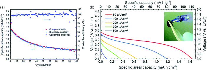 | ||
| Fig. 12 (a) Charge–discharge capacity vs. number of cycles of the LiCoO2/Ta-LLZO/Li-In cell with a current 50 μA cm−2 between 2.4–3.6 V at 50 °C. (b) Discharge performance at different discharge current densities.96 Reproduced with permission from ref. 96. Copyright (2019), Royal Society of Chemistry. | ||
4.2 Perovskite
Perovskite materials have the generic formula ABX3 and are made of corner shared BX6 octahedra and A located at dodecahedral sites as shown in Fig. 13. Lithium lanthanum titanates (LLTO) with composition Li3xLa(2/3)−xTiO3 (1/25 < x < 1/6) are the most promising electrolytes in the perovskite family because of their high bulk conductivities reaching ∼10−3 S cm−1.140 Lithium and lanthanum share occupation of the A sites while titanium fully occupies the B sites. The ionic conductivity of perovskite ISE is strongly dominated by the grain boundary conductivity that is very poor ∼10−4–10−5 S cm−1; however, substitutions can reduce the substantial grain boundary resistance. Table 3 summarizes the impact of substitutions made into LLTO and the resulting effect on total conductivity. The lattice size changes by introducing different size substituents to the A-site such as subvalent partial substitution of La3+ by larger ionic radius Sr2+ expands the lattice size leading to lower barrier energy and increases the lithium concentration by charge compensation. These two factors enhance the bulk conductivity.141 Likewise, partial substitution on the b-site affects the ionic conductivity. Similar to the other ISE families, substituting Ti4+ with Ge4+ increases the density of the solid electrolyte, which in turn improves the total conductivity by improving the transport at the grain boundaries.142 On the other hand, although partial substitution of Ti4+ by Nb5+ lowers the bulk conductivity, it also yields a higher grain boundary conductivity, which is the limiting factor of LLTO total conductivity such that Nb-substitution does improve the overall conductivity.143 A disadvantage of LLTO electrolyte is that it gets lithiated by the metallic lithium anode converting into conductive phase thereby preventing its integration into ASSLB with Li metal anode.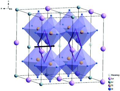 | ||
| Fig. 13 Crystal structure of LLTO and the square oxygen window through which the Li ions hope.141 Reproduced with permission from ref. 141. Copyright (2019), Elsevier. | ||
| Composition | Synthesis method | Sintering temperature/time | σ Total (S cm−1) | E a (eV) | σ electronic (S cm−1) | ρ/ρo (%) | Ref. |
|---|---|---|---|---|---|---|---|
| Li0.5La0.5Nb0.04Ti0.95O3 | Solid state | 1350 °C for 12 h | 1.04 × 10⁻⁴ | — | — | — | 143 |
| Li0.36La0.53Sr0.03TiO3 | Sol–gel | 1250 °C for 4 h | 1.95 × 10⁻³ | 0.3 | — | 97.31 | 141 |
| Li0.35La0.35Sr0.3TiO3 | Solid state | 1300 °C for 6 h | 2.78 × 10⁻⁵ | 0.3 | — | 97.17 | 144 |
| Li0.355La0.35Sr0.3Ti0.995Al0.005O3 | Solid state | 1300 °C for 6 h | 2.05 × 10⁻⁵ | 0.31 | — | 96.56 | 144 |
| Li0.355La0.35Sr0.3Ti0.995Co0.005O3 | Solid state | 1300 °C for 6 h | 1.37 × 10⁻⁵ | 0.32 | — | 96.99 | 144 |
| Li0.355La0.35Sr0.3Ti0.995In0.005O3 | Solid state | 1300 °C for 6 h | 1.97 × 10⁻⁵ | 0.31 | — | 97.15 | 144 |
| Li0.43La0.56Ti0.95Ge0.05O3 | Solid state | 1150 °C for 2 h | 1.20 × 10⁻⁵ | — | 5.2 × 10⁻⁷ | — | 142 |
| (Li0.33La0.56)1.005Ti0.99Al0.01O3 | Sol–gel | 1350 °C for 6 h | 3.17 × 10⁻⁴ | — | 2.3 × 10⁻¹² | — | 145 |
4.3 NASICON-type
NASICON-type ISEs are lithium ion conductors with the structure of a sodium super ionic conductor with chemical formula LiM2(XO4)3. The structure, shown in Fig. 14, is rhombohedral and can be described in the R![[3 with combining macron]](https://www.rsc.org/images/entities/char_0033_0304.gif) c space group. It is made of XO4 tetrahedra at 18e site and MO6 octahedra at 12c sites joined by corner sharing while the lithium ions fully occupy antiprismatic 6b sites (Li1). LiM2(XO4)3 has many polymorphs, but the rhombohedral structure yields the highest ionic conductivity. Fig. 15 shows the various substitutions attempted to improve this class of electrolytes. These substitutions are on two sites: the X sites (P, Si) and the M sites (Ge, Ti, Sc, Zr, Hf). For the M sites, the activation energy decreases as the ionic radius increases due to the larger lattice with expanded bottleneck size as shown in Fig. 16. However, when we resort to larger radii cations such as Zr, Hf, and Sc, the expansion of the lattice causes a structural distortion wherein Li ions move to a more stable site (M2) and transforms the structure into monoclinic/triniclic phases that are poorly conductive. The optimum M substitution in terms of ionic conductivity is therefore considered to be Ge as illustrated in Fig. 15. Three classes of NASICON-type materials have been studied with parent structures with M = Ti (LTP), Ge (LGP), and Zr (LZP). The rest of this section discusses progress in these families.
c space group. It is made of XO4 tetrahedra at 18e site and MO6 octahedra at 12c sites joined by corner sharing while the lithium ions fully occupy antiprismatic 6b sites (Li1). LiM2(XO4)3 has many polymorphs, but the rhombohedral structure yields the highest ionic conductivity. Fig. 15 shows the various substitutions attempted to improve this class of electrolytes. These substitutions are on two sites: the X sites (P, Si) and the M sites (Ge, Ti, Sc, Zr, Hf). For the M sites, the activation energy decreases as the ionic radius increases due to the larger lattice with expanded bottleneck size as shown in Fig. 16. However, when we resort to larger radii cations such as Zr, Hf, and Sc, the expansion of the lattice causes a structural distortion wherein Li ions move to a more stable site (M2) and transforms the structure into monoclinic/triniclic phases that are poorly conductive. The optimum M substitution in terms of ionic conductivity is therefore considered to be Ge as illustrated in Fig. 15. Three classes of NASICON-type materials have been studied with parent structures with M = Ti (LTP), Ge (LGP), and Zr (LZP). The rest of this section discusses progress in these families.
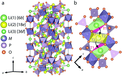 | ||
| Fig. 14 Crystal structure of LiM2(PO4)3 with NASICON structure (a), an illustration of the triangular oxygen bottleneck T1, T2 (b).159 Reproduced with permission from ref. 159. Copyright (2018), American Chemical Society. | ||
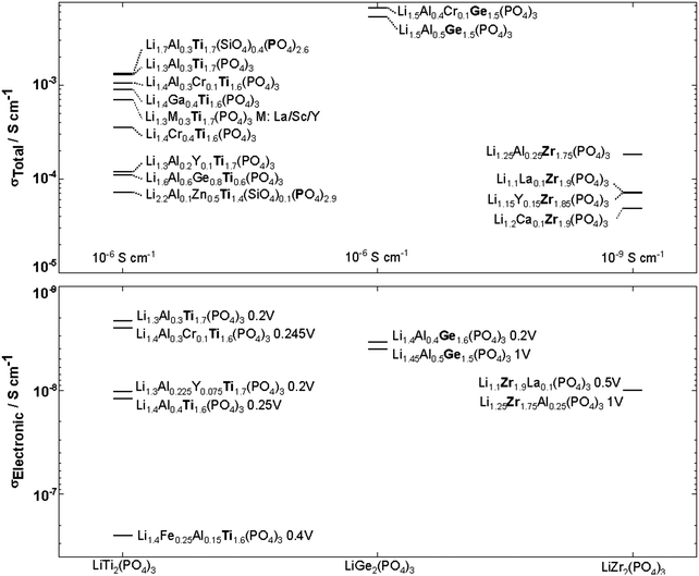 | ||
| Fig. 15 NASICON-like structures substitutions in LiM2(PO4)3 M:Ti, Ge, Zr and their corresponding ionic and electronic conductivity with the applied DC voltage indicated next to the compound name. 9,160–172 | ||
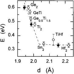 | ||
| Fig. 16 The bulk activation energy vs. the bottleneck size between Li1 and Li3 in NASICON-like ISEs.173 Reproduced with permission from ref. 173. Copyright (1998), American Chemical Society. | ||
Although LiGe2(PO4)3 LGP can be synthesized in the rhombohedral structure without any substituents, the conductivity is quite small (∼10−6 S cm−1). All the Li ions occupy the 6b site with the 18e site vacant. Fig. 15 shows that subvalent partial substitutions of Ge4+ with Cr3+ and Al3+ dramatically improves the conductivity. This is attributed to lithium ions now occupying both the 6b and 18e sites. Subvalent substitution of LGP by Al3+ introduces additional lithium ions to the Li3 site and due to the repulsion with the Li1 site, the lithium ions redistribute between Li1 and Li3. This repulsion causes the volume of the LiO6 octahedra to increase, expanding c of the lattice, but the size of the oxygen triangle windows T1 and T2 shown in Fig. 14 does not expand. The coulombic interaction between Li1 and Li3 pushes Li1 into Li3*, which acts as a spring flattening Li ion energy landscape, decreasing the activation energy. Therefore the mechanism behind the conductivity enhancement of Al-LGP is that by increasing the energy of lithium, the local minima become less profound, thereby decreasing the migration barriers.146 Optimal Al3+ substitution content of 0.4 mol per unit formula of LGP achieves room temperature total conductivity of 1.22 × 10⁻³ S cm−1 which is three order of magnitude higher than of unsubstituted LGP and is certainly of interest in real battery applications.147 Higher substituent content increases activation energy due to the smaller bottleneck size.148 Further co-substituting with Y tweaks the microstructure and grain morphology producing a denser product with lower intergrain resistance.149 Other co-substitution explored on Al-LGP is Sr where due to its large ionic radius has limited solubility of 0.17 per unit formula above which secondary phase (ScPO4) forms at the grain boundary lowering intergrain lithium diffusion. Higher Sr contents also distorts the cubic phase as mentioned above. The optimal composition of Li1.5Al0.33Sc0.17Ge1.5(PO4)3 shows higher conductivity than LGP due to the larger Li diffusion channel size and facilitating new diffusion channels direct 6b–36f path through which the Li ions move in concerted fashion instead moving through 18e by isolated single-ion diffusion.150 One drawback of LGP is that it gets reduced when in contact with metallic lithium anodes yielding an electronically conductive material.151
LiZr2(PO4)3 (LZP) has four polymorphs which are presented in Fig. 17. At synthesis temperature above 1100 °C, α′ triclinic phase (P![[1 with combining macron]](https://www.rsc.org/images/entities/char_0031_0304.gif) ) forms which transforms into α rhombohedral phase (R
) forms which transforms into α rhombohedral phase (R![[3 with combining macron]](https://www.rsc.org/images/entities/char_0033_0304.gif) c) at around 40 °C. Whereas the β′ monoclinic phase (P21/n) forms at synthesis temperatures below 1100 °C and transforms into β orthorhombic phase (Pbna) at around 300 °C. Both α and β has ionic conductivity but α phase has higher. Thus, lowering the transition temperature to stabilize room temperature α phase is a promising strategy to achieve high conductivity. Such stabilization of the R
c) at around 40 °C. Whereas the β′ monoclinic phase (P21/n) forms at synthesis temperatures below 1100 °C and transforms into β orthorhombic phase (Pbna) at around 300 °C. Both α and β has ionic conductivity but α phase has higher. Thus, lowering the transition temperature to stabilize room temperature α phase is a promising strategy to achieve high conductivity. Such stabilization of the R![[3 with combining macron]](https://www.rsc.org/images/entities/char_0033_0304.gif) c phase is accomplished by subvalent substitution of LZP with La3+ such substitutions are shown in Fig. 15. Moreover, the lithium concentration is increased by neutrality preservation and due to its larger ionic radius, the lattice size and triangle bottleneck window size expands leading to lower migration energy. The sum effect is enhanced bulk conductivity. It worth mentioning that different synthesis methods can also lower the phase transition temperature. For example, the sol–gel method can stabilize the rhombohedral without any substitution by reducing the α′ to α LZP phase transition temperature from 40 to 15 °C, yielding total and bulk conductivities of 1.5 × 10⁻⁶ and 1.5 × 10⁻⁴ S cm−1, respectively.152
c phase is accomplished by subvalent substitution of LZP with La3+ such substitutions are shown in Fig. 15. Moreover, the lithium concentration is increased by neutrality preservation and due to its larger ionic radius, the lattice size and triangle bottleneck window size expands leading to lower migration energy. The sum effect is enhanced bulk conductivity. It worth mentioning that different synthesis methods can also lower the phase transition temperature. For example, the sol–gel method can stabilize the rhombohedral without any substitution by reducing the α′ to α LZP phase transition temperature from 40 to 15 °C, yielding total and bulk conductivities of 1.5 × 10⁻⁶ and 1.5 × 10⁻⁴ S cm−1, respectively.152
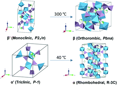 | ||
| Fig. 17 Crystal structures of the different polymorphs of LiZr2(PO4)3.174 Reproduced with permission from ref. 174. Copyright (2017), American Chemical Society. | ||
LTP conductivity is enhanced by subvalent substitution as shown in Fig. 15 such as with Al3+, Cr3+.153 The mechanism of the ionic conductivity enhancement is the same as in the subvalent substitution of LGP. The lithium in Al-LTP moves through the Li1–Li3–Li3–Li1 pathway which is explored by maximum-entropy method (MEM)154 Introducing Al to LTP in the range of 0.1–0.5 mol per unit formula increases the bulk conductivity three orders of magnitude to reach ∼10−3 S cm−1 which was measured on a single crystal.155 Low temperature EIS was used to separate the bulk and grain conductivities in polycrystalline samples of LATP as shown in the Arrhenius plots in Fig. 18. This reveals poor grain boundary conductivity with a high activation energy. Furthermore, Fig. 18 also shows that LATP has a decreasing bulk conductivity when exposed to air and the process can be reversed with heating.44 Ti4+-Based NASICON-type LTP gets reduced by Li metal into an electronically conductive phase. Thus, a buffer layer is currently required (e.g. LIPON layer156 or polymer electrolyte157) in order to protect the LATP.
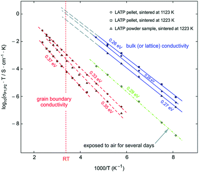 | ||
| Fig. 18 Arrhenius plot of LATP sintered at different temperatures the blue line corresponds to the bulk conductivity which was separated from grain boundary at low temperatures and extrapolated to room temperature. The green, the red line corresponds to the grain boundary and the green to the bulk conductivity after exposing the sample to air. 44 Reproduced with permission from ref. 44. Copyright (2015), Royal Society of Chemistry. | ||
Still of interest for further study, this class of material may yet be optimized with further substitutions. It should however be noted that these materials are extremely rigid such that assembly in a ASSLB is difficult and maintaining the battery structure during operation is very difficult unless low volume expansion electrodes are used and this greatly limits the energy density.158
4.4 LISICON
Lithium super ionic conductor (LISICON) is a family of materials with the structure of Li4SiO4 or γ-Li3PO4 with monoclinic and orthorhombic structures, respectively, as shown in Fig. 19. Both are made of XO4 tetrahedra (X = P, Si), but with different orientations. The three lithium ions per unit formula of γ-Li3PO4 are located at the tetrahedral 8d and 4c sites. The XO4 tetrahedral site can be partially substituted by different valence cations changing the charge carrier concentration and lattice size, hence tuning the ionic conductivity. Table 4 shows the resulting conductivities for the various substitutions attempted into these structures. Here, we focus on the one material that has a conductivity about 5 × 10⁻⁵ S cm−1 (W substituted Li–Ge–O) and refer a reader interested in this class of materials to a review article explores this class more.175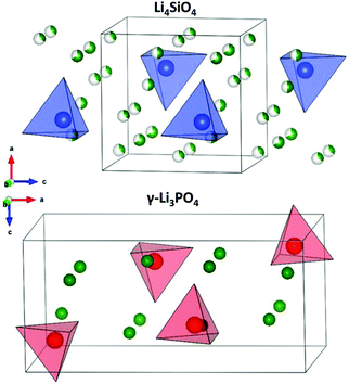 | ||
| Fig. 19 Crystal structures of LISICON solid electrolytes.177 Reproduced with permission from ref. 177. Copyright (2015), American Chemical Society. | ||
| Composition | σ Total (S cm−1) | E a (eV) | Ref. |
|---|---|---|---|
| Li3.6Ge0.8S0.2O4 | 2.00 × 10⁻⁵ | — | 178 |
| Li3.5Co0.25GeO4 | 8.40 × 10⁻⁶ | 0.71 | 179 |
| Li3.75Ge0.75V0.25O4 | 7.50 × 10⁻⁶ | 0.54 | 176 |
| Li3.70Ge0.85W0.15O4 | 5.0 × 10⁻⁵ | 0.41 | 176 |
| Li3PO4 | 5.10 × 10⁻⁷ | 0.59 | 180 |
| Li3.5Si0.5P0.5O4 | 1.60 × 10⁻⁶ | 0.54 | 180 |
| Li4SiO4 | 1.20 × 10⁻⁸ | 0.64 | 180 |
| Li4.5Si0.5Al0.5O4 | 2.30 × 10⁻⁷ | 0.56 | 181 |
| Li3.55(Ge0.45Si0.10V0.45)O4 | 1.00 × 10⁻⁵ | 0.37 | 182 |
| Li3.53(Ge0.75P0.25)0.7V0.3O4 | 5.10 × 10⁻⁵ | 0.43 | 183 |
| Li3.47Si0.5P0.5Cl0.03O3.97 | 1.03 × 10⁻⁵ | 0.44 | 184 |
| Li3.47Ge0.5P0.5Cl0.03O3.98 | 3.70 × 10⁻⁵ | 0.39 | 184 |
Li3.70Ge0.85W0.15O4 has a dramatically improved conductivity compared to the parent Li4GeO4 due to the supervalent W6+ substitution creating Li vacancies, and enlarging the oxygen windows such that the Li-diffusion energy barrier is lower.176 The drawback of LISICON is that they have high conductivity only at high temperatures; for instance Li3.5Si0.5P0.5O4 has a room temperature conductivity of ∼10−7 S cm−1 and ∼10−3 S cm−1 at 300 °C. At low temperature ordering of the interstitial lithium ions decreases the conductivity. However, at high temperature the two octahedral interstitial sites become partially occupied with weaker interaction with the oxygen at high temperature that lowers the activation energy. The ionic conductivity of LICISON is modest and still needs further enhancement.
4.5 Thio-LISICON
The anionic substitution of O2− by more polarizable S2− in the LISICON materials discussed in the previous section leads to orders of magnitude higher ionic conductivity ISE called thio-LISICON. The structure of thio-LISICON is the same structure as the LISICON only O2− is replaced by a more polarizable S2− anion. Li4GeS4 has β-Li3PS4 thio-LISICON structure and can be represented in the Pnma space group. When Ge is substituted by Sn forms a solid solution Li4Ge1−xSnxS4. Although the introduction of larger ionic radius Sn increases the triangular bottleneck window but does not affect the ionic conductivity because it enhances only short-range diffusion. However, the Li4SnS4 end of the solid solution shows an order of magnitude higher ionic conductivity 1.4 × 10⁻⁶ S cm−1 due to the enhanced short range diffusion combined with the reposition/redistribution of lithium ions which decreases the Li1–Li2 distance shown in Fig. 20(c) converting their configuration from edge shared to face shared facilitating long range diffusion chain along the b-axis. Moreover, the introduction of new partially occupied Li4 sites enables 3D conduction by connecting the linear diffusion paths as shown in Fig. 20(d).185 The low ionic conductivity of Li4SnS4 can be enhanced by substituting it with As forming Li4−xSn1−xAsxS4 (x = 0 to 0.250) solid solution with the highest ionic conductivity being 1.39 × 10⁻³ S cm−1 for Li3.833Sn0.833As0.166S4.186 The advantage of the thio-LISICON mentioned above compared to thiophosphate based ISEs that are discussed below is their air stability because thiophosphates react with moister to release H2S gas. The ionic conductivity of parent β-Li3PS4 increases 3 order of magnitude by substituting P with Si. It forms a very limited solid solution Li3+x[SixP1−x]S4 (0.15 < x < 0.33) where the β-Li3PS4 structure is entropy stabilized by splitting lithium site causing disorder which flattens the energy landscape thus reaching ionic conductivity of 1.22 × 10⁻³ S cm−1 for Li3.25[Si0.25P0.75]S4.187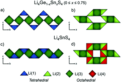 | ||
| Fig. 20 Li ion polyhedra of Li4Ge1−xSnxS4 (0 × 0.75) along a–b plane (a) and a–c plane (b) Li4SnS4 along a–b plane (a) and a–c plane (b)185 reproduced with permission from ref. 185. Copyright (2019), American Chemical Society. | ||
Furthermore, the Li4GeS4–Li3PS4 solid solution is divided into three regions (I, II, and III), as shown in Fig. 21, according to their superstructures caused by the different cation ordering. In this solid solution, Li3.25Ge0.25P0.75S4 has the highest conductivity. The Li2GeS4–Li2PS4 phase diagram is shown in Fig. 22, which reveals the regions where each phase the thio-LISICON and LGPS (discussed separately later in this review) exists. The downside of Li3.25Ge0.25P0.75S4 is its instability against lithium. Substitution of Ge by Al into Li(4−1/3)Al1/3P2/3S4 enhances stability against lithium but lowers the conductivity to 8.02 × 10⁻⁴ S cm−1 at 25 °C.188
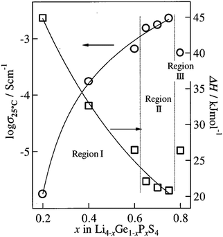 | ||
| Fig. 21 The ionic conductivity of the different regions of Li2GeS4–Li2PS4 solid solution.191 Reproduced with permission from ref. 191. Copyright (2001), Electrochemical Society. | ||
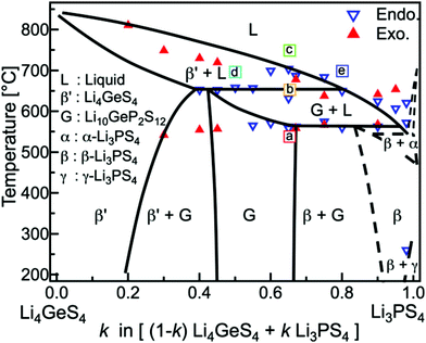 | ||
| Fig. 22 Li2GeS4–Li2PS4 phase diagram shows the thio-LISICON and LGPS regions.192 Reproduced with permission from ref. 192. Copyright (2015), John Wiley and Sons. | ||
This impressive class of solid electrolytes is receiving a great deal of interest in all solid batteries, so we now briefly summarize the state-of-the-art in thio-LISICON ASSLB. Alloy anodes are widely used to integrate sulfide electrolytes in all-solid-state batteries since they are unstable against lithium anode. Although the potential of alloy anodes still are outside the electrochemical stability window of sulfide electrolytes, its reduction thermodynamic driving force is lower compared to lithium anode. Such alloying metals are Al, Ga, In, Sn, or Sb; from this list In is the most promising because of its ductility.189 Moreover, sulfide-based electrolytes have a low upper electrochemical stability window such that a buffer layer between the cathode and electrolyte is needed. On the contrary, it is compatible with the sulfur cathode, making it a good candidate for Li–S batteries. Recently, an impressive areal capacity of 7.8 mA h cm−2 was obtained for a Li–S cell utilizing Li3PS4 as the electrolyte (this is well above the roughly 3 mA h cm−2 achieved in cathodes for state-of-the-art Li-ion batteries discussed in part I of this review). It should be noted that this performance was obtained at a slow cycling of about C/65 (the current density was 0.12 mA cm−2) and the capacity faded rapidly within a few cycles, indicating that much work is needed to further improve the performance of all-solid batteries.190 In Fig. 23(a) the electrochemical performance of 7.7 mg cm−2 loading at different cycles is show. At higher loadings as shown in Fig. 23(c) the gravimetric capacity dropped due the higher polarization of thick electrode. Although as shown in Fig. 23(b) the coulombic efficiency of high loading cell is almost 100% for the first 10 cycles but the charge discharge capacity dropped. Furthermore, the cell configuration had an average voltage in the range 1.2–1.5 V, thereby making their energy about 80% that of current Li-ion batteries operating at average voltage of about 3.8–3.9 V (as discussed in part I of this review). Nonetheless, these full solid-battery results are extremely promising and will undoubtedly encourage a great deal of further interest in ASSLB designs with thio-LISICON electrolytes.
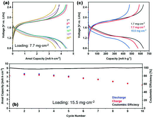 | ||
| Fig. 23 Charge–discharge profile of S/VS2/Li3PS4|Li3PS4|Li/In (a) for different cycles of 7.7 mg cm−2 loading (c) for different loadings. (b) Charge, discharge, and coulombic efficiency vs. cycle number for of S/VS2/Li3PS4|Li3PS4|Li/In with 15.5 mg cm−2 loading.190 Reproduced with permission from ref. 190. Copyright (2020), John Wiley and Sons. | ||
4.6 Argyrodite
Argyrodite has Li7PS6 chemical formula with two polymorphs. Fig. 24 shows both structures: the low ionic conductivity room temperature tetragonal phase (Pna21) and the high conductivity high temperature cubic phase (F![[4 with combining macron]](https://www.rsc.org/images/entities/char_0034_0304.gif) 3m). The framework of the cubic phase is made of PS4 tetrahedra located at the 4b site and S2− atoms located at the 4a, 4d, and 16e site while the lithium ions are found at the interstitial sites. The cubic structure is stabilized at room temperature by anionic or cationic substitutions. Anionic partial substitution such as substituting S2− by halide leads to Li6PS5X (X = Cl, Br, I).193 The introduction of more polarizable halides softens the lattice decreasing the activation energy. The softer lattice of Li6PS5Br compared to Li6PS5Cl causes a decrease of the pre-exponential factor. In Br− and Cl− substitution, the structure is disordered where the 4d S2− site is mixed occupied S2−/X− leading to enhanced conductivity. On the other hand, Li6PS5I has very low ionic conductivity because of the ordered structure due to the difference in the ionic size of S2− and I−. There are three possible lithium migration paths divided into intercage and intracage as shown in Fig. 24. S2−/I− disorder facilitates the intracage transport, thus enhancing the ionic conductivity.194 In contrast, partial subvalent cation substitution of P5+ at the 4b site by for example, Si4+ or Ge4+ produces solid solution Li7+xMxP1−xS6 (M = Si, Ge) where the conductivity is improved by stabilizing the cubic phase. The ionic conductivity in these solid solutions increases to a specific substituent content, after which decreases.195 Both Ge4+ and Si4+ substitution regardless of their radius cause S2−/I− disorder and increase the lithium occupancy at both the 24g and 48h sites which lead to stronger Li–Li coulombic interactions causing an increase in the double jump path and wider jump through a trigonal planer window and intercage jump through a polyhedral window. In other words, it flattens the potential surface; hence the activation energy decreases.196 Moreover, Si4+ substitution expands the electrochemical stability window to reach 6 V. 197 Although Li6PS5I has low conductivity as mentioned above, iodine based interface helps to form uniform plating and stripping against the lithium anode threby reducing dendrite formation. Cationic substitution of P5+ by Sn4+ in Li7PS6 is not possible but becomes possible in Li6PS5I since it has a larger lattice. The larger lattice size caused by larger ionic radius of Sn4+ compared to P5+ and higher lithium content in Li6+xP1−xSnxS5I enhances conductivity. Furthermore its air stability improved because Sn is soft acid and prefers to bond to soft base S2− in contrast P5+ is prone to oxidation where PS4 reacts with water forming H2S.198 Analogous to Li6+xMxP1−xS5I (M = Si, Ge, Sn), thioantimonate argyrodite Li6+xMxSb1−xS5I (M = Si, Ge, Sn) yields an impressive ionic conductivity of 2.4 × 10⁻² S cm−1 for Li6.6Si0.6Sb0.4S5I which is among the highest reported solid electrolyte ionic conductivities. This high ionic conductivity is due to minor S2−/I− disorder and significant lithium cation disorder.61 The drawback of argyrodite solid electrolyte, like other sulfur based electrolytes, is sensitivity to air where it reacts with the water in the air to form H2S.
3m). The framework of the cubic phase is made of PS4 tetrahedra located at the 4b site and S2− atoms located at the 4a, 4d, and 16e site while the lithium ions are found at the interstitial sites. The cubic structure is stabilized at room temperature by anionic or cationic substitutions. Anionic partial substitution such as substituting S2− by halide leads to Li6PS5X (X = Cl, Br, I).193 The introduction of more polarizable halides softens the lattice decreasing the activation energy. The softer lattice of Li6PS5Br compared to Li6PS5Cl causes a decrease of the pre-exponential factor. In Br− and Cl− substitution, the structure is disordered where the 4d S2− site is mixed occupied S2−/X− leading to enhanced conductivity. On the other hand, Li6PS5I has very low ionic conductivity because of the ordered structure due to the difference in the ionic size of S2− and I−. There are three possible lithium migration paths divided into intercage and intracage as shown in Fig. 24. S2−/I− disorder facilitates the intracage transport, thus enhancing the ionic conductivity.194 In contrast, partial subvalent cation substitution of P5+ at the 4b site by for example, Si4+ or Ge4+ produces solid solution Li7+xMxP1−xS6 (M = Si, Ge) where the conductivity is improved by stabilizing the cubic phase. The ionic conductivity in these solid solutions increases to a specific substituent content, after which decreases.195 Both Ge4+ and Si4+ substitution regardless of their radius cause S2−/I− disorder and increase the lithium occupancy at both the 24g and 48h sites which lead to stronger Li–Li coulombic interactions causing an increase in the double jump path and wider jump through a trigonal planer window and intercage jump through a polyhedral window. In other words, it flattens the potential surface; hence the activation energy decreases.196 Moreover, Si4+ substitution expands the electrochemical stability window to reach 6 V. 197 Although Li6PS5I has low conductivity as mentioned above, iodine based interface helps to form uniform plating and stripping against the lithium anode threby reducing dendrite formation. Cationic substitution of P5+ by Sn4+ in Li7PS6 is not possible but becomes possible in Li6PS5I since it has a larger lattice. The larger lattice size caused by larger ionic radius of Sn4+ compared to P5+ and higher lithium content in Li6+xP1−xSnxS5I enhances conductivity. Furthermore its air stability improved because Sn is soft acid and prefers to bond to soft base S2− in contrast P5+ is prone to oxidation where PS4 reacts with water forming H2S.198 Analogous to Li6+xMxP1−xS5I (M = Si, Ge, Sn), thioantimonate argyrodite Li6+xMxSb1−xS5I (M = Si, Ge, Sn) yields an impressive ionic conductivity of 2.4 × 10⁻² S cm−1 for Li6.6Si0.6Sb0.4S5I which is among the highest reported solid electrolyte ionic conductivities. This high ionic conductivity is due to minor S2−/I− disorder and significant lithium cation disorder.61 The drawback of argyrodite solid electrolyte, like other sulfur based electrolytes, is sensitivity to air where it reacts with the water in the air to form H2S.
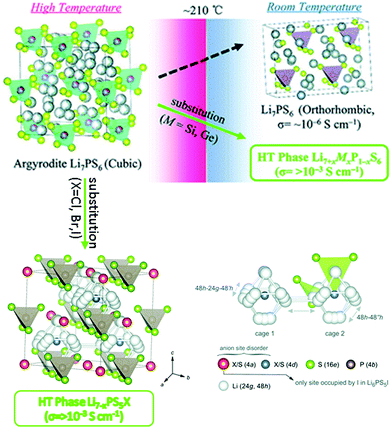 | ||
| Fig. 24 High and low temperature polymorphs of Argyrodite and the mechanisms used to lower the phase transition temperature by cationic and anionic substitution.195,201 Reproduced with permission from ref. 195 and 201. Copyright (2019), Royal Society of Chemistry. | ||
Due to the narrow electrochemical stability window (1.25–2.50 V) of argyrodite type ISE,199 their integration into an ASSLB requires ISE/electrode buffer layer. A promising argyrodite based ASSLB configuration is LiNi1/3Mn1/3Co1/3O2@Li0.35La0.5Sr0.05TiO3/Li6PS5Cl/Li–In, where the cathode active material is coated with Li0.35La0.5Sr0.05TiO3 to prevent electrolyte oxidation while using Li–In anode to prevent its reduction. This configuration exhibits a capacity of 97 mA h g−1 at the 850th cycle under C/3 with an applied external pressure of 50 MPa.200
4.7 LGPS-like
Li10GeP2S12 (LGPS) structure as shown in Fig. 25(b) consists of two tetrahedral sites where the 4d site is mixed occupied by Ge/P and the 2b site is fully occupied by P. There are four lithium sites two of each is fully occupied and the other two 16h and 8f sites are partially occupied making a chain along c-axis. The fully occupied lithium octahedral 4d site connects the XS4 tetrahedra along the a-axis through edge sharing with the tetrahedra at 4d site and corner sharing with PS4. While the other 4c fully occupied lithium site connects the PS4 tetrahedra along the a-axis through edge sharing with tetrahedra at 4d site and corner sharing with XS4. The lithium transport pathway is through the chain of interstitials at the 16h and 8f sites along the a-axis.69 These 1D lithium diffusion paths are interconnected by 8f–4d–8f and 16h–4c–16h lithium paths enabling 3D lithium diffusion as shown in Fig. 25(c).56 Although substituting of Ge4+ by Sn4+ expands the unit cell, the bottleneck size S3–S2 shown Fig. 26 becomes smaller, leading to higher migration energy.202 Moreover, this substitution causes the lattice to soften and the coulombic interaction between S2− and Li+ to increase because of the longer Sn–Li bond and lower electronegativity making the S more electron dense which all likewise increases the activation energy.11Table 5 summarizes the substitutions in LGPS like structure. The drawback of LGPS family ISE their very narrow electrochemical stability window because sulfur and phosphorus are prone to oxidation and reduction, respectively. When LGPS is used with metal anode, it degrades into Li2S Li3P and Ge–Li alloy leading to interfacial resistance growth. The ionic conductivity of Li2S dictates this resistance growth. The decomposition rate of LGPS against lithium anode extrapolates to a 4.6 kΩ cm2 interfacial resistance within a year increasing the cell overpotential (internal resistance).203 Its narrow electrochemical stability window can be resolved by adding buffer layer such as coating the LCO cathode with LiNbO3 and in situ formation of LiH2PO3 on the lithium anode.204 Substitution in LGPS has been investigated computationally for Li10±1MP2X12 (M: Ge, Si, Sn, Al or P, and X: O, S or Se).205 The anionic substitution of S2− by O2− decreases the conductivity because of its smaller ionic radius and polarizability compared to sulfur. This substitution narrows the lithium diffusion path, however, moving to Se doesn’t enhance the conductivity further which means an optimal channel size is obtained with S2−. By contrast, the effect of cationic substitution on the ionic conductivity is small, as shown in the Table 6.205 As an effort to enhance the narrow electrochemical stability window of LGPS, partial substitutions such as Li+/Ba2+ and S2−/O2− have been performed, where the ionic conductivity remained high and a higher electrochemical stability was reported.206,207 These electrochemical stability windows are overestimated because they were measured on a Li/SE/Au cell that is flawed as discussed earlier, but the fact that the substitutions yield improvements is sound.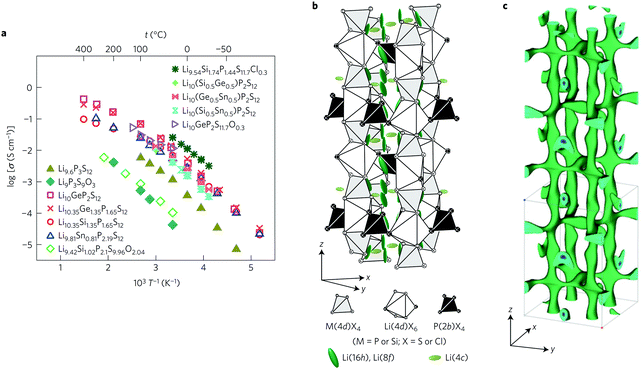 | ||
| Fig. 25 (a) The Arrhenius plot of different composition solid electrolyte with LGPS structure. (b) Crystal structure of Li10±1MP2X12 with LGPS structure, and (c) lithium diffusion path.208 Reproduced with permission from ref. 208. Copyright (2016), Springer Nature. | ||
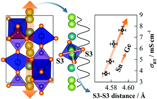 | ||
| Fig. 26 Illustration of the effect of Sn4+/Ge4+ substitution on the S3–S3 bottleneck size and hence the ionic conductivity.11 Reproduced with permission from ref. 11. Copyright (2018), American Chemical Society. | ||
| Composition | σ Total (mS cm−1) | E a (eV) |
|---|---|---|
| Li10GeP2S12 | 13 | 0.21 |
| Li10SiP2S12 | 23 | 0.20 |
| Li10SnP2S12 | 6 | 0.24 |
| Li9P3S12 | 4 | 0.26 |
| Li11AlP2S12 | 33 | 0.18 |
| Li10GeP2S12 | 24 | 0.19 |
| Li10GeP2O12 | 0.03 | 0.36 |
The state-of-the-art for LGPS ASSLB is impressive. Fig. 25(a) shows the Arrhenius plot of LGPS-like structure ISE with different substitutions/compositions accomplished in the literature. The optimal chemical formula Li9.54Si1.74P1.44S11.7Cl0.3 with LGPS structure holds the record with an ionic conductivity of 2.5 × 10⁻² S cm−1.208 In an all solid battery with the LiCoO2 + LGPS/LGPS/Li configuration, the instability of LGPS against the cathode and anode was resolved by buffer layers on each electrode, thereby achieving a capacity of 113.7 mA h g−1 at the 500th cycle at a cycling rate of 0.1C.204 Despite the challenges with air stability, this class of ISEs will continue to receive a great deal of attention due to the unmatched ionic conductivities.
4.8 Anti-perovskite
While all the previously discussed classes of structures have been studied for a significant period of time that has allowed time for significant exploration of the impact of substitution, anti-perovskites represent a newer class of ISEs where the impact of substitutions has not been explored so thoroughly. Anti-perovskite has the same structure as perovskite with inverted charges where oxygen occupies the octahedral B site OLi6 with the lithium ions at the vertices, and the dodecahedral A site is occupied by a halide or hydroxide with conductivity reaching around ∼10−3 S cm−1. The performance of lithium rich anti-perovskites Li3OA is enhanced by tuning the content of A site. The conductivity enhancement moving from I− to Cl− results from the optimal radius size ratio of Cl− to O and Li expanding the Li ion transport channel reaching room temperature conductivity of 8.5 × 10⁻⁴ S cm−1.210 Partial substitution of the Li can tune the charge carriers concentration. Perfect lithium anti-perovskite crystal is not conducive due to the absence of lithium vacancies. The presence of point defects Frenkel or Schottky (LiA deficiency) improves its conductivity. The conductivity of anti-perovskite can be enhanced by anionic mixing and cationic partial substitution.141 Partial substitution of Li by divalent cation such as Ba2+ incorporates vacancies into the structure, improving the performance of the glassy ISE.211 Hydrogen substitution to obtain Li3−xOHxCl lowers energy barriers by facilitating Schottky defects formation.212 A site mixing can generate lattice mismatch which improves lithium diffusion for instance, Li3OCl1−xBrx has conductivity higher than the end members.213 One the other B site partial substitution of O2− by S2− produces double perovskite with lower defect formation energy, hence improving room temperature conductivity.214 It worth mentioning that in all these anti-perovskite structures, slight off stoichiometry can produce vacancy facilitating the lithium transport through vacancy hopping route. The ordered vacancy in Li2OHCl orthorhombic structure at high temperature converts into cubic phase shown in Fig. 27(a) with disordered vacancy enhancing the conductivity. The partial substitution of OH− by F− stabilizes the cubic phase at room temperature and reduces the number of −OH groups which hydrogen hinters lithium motion; thus, the conductivity increases.215 On the other hand the substitutions that introduce octahedra tilting or and distortion as shown in Fig. 27(b) decreases the ionic conductivity.216 The disadvantage of anti-perovskite ISE is their low oxidation potential which was predicted by DFT calculation to be between 2.5–3.0 V,217,218 which currently limits their application to low voltage battery. We consider this class of ISE to be significantly improved by further substitution studies, with a particular focus on the stability against the cathode.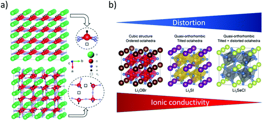 | ||
| Fig. 27 (a) Transition from orthorhombic with ordered vacancy to cubic structure with disordered vacancy by partial substitution of −OH by F−.212 Reproduced with permission from ref. 212. Copyright (2018), Royal Society of Chemistry. (b) Different substitution that leads the ionic conductivity to decrease due to the distortions.216 Reproduced with permission from ref. 216. Copyright (2019), Royal Society of Chemistry. | ||
5. Summary and conclusions
5.1 Design principles for optimizing solid electrolytes
The impact of metal substitutions into inorganic solid electrolytes on electrochemical properties and the underlying mechanism were reviewed. Substitutions in ISEs can enhance bulk ionic conductivity by increasing the Li carrier concentration and decreasing the bottleneck energy. There are a number of important design principles that were discussed throughout this review. These can be summarized as follows.In order to use metal substitutions to enhance the total ionic conductivity, this can be done either by tuning:
(1) The bulk conductivity (structure tuning):
• Tuning lattice volume by isovalent substitution to lower the bottleneck (barrier) energy.
• Induce lattice distortion.
• Increase Li sublattice disorder through aliovalent substitution by creating Li vacancies.
• Stabilize the high-temperature ion conductive phase by substitution.
• Create defects by aliovalent substitution through charge compensation via introducing or increasing the concentration of the vacancies or interstitial Li ions.
• Tweak the potential energy surface of the Li ion by inserting Li ions into high-energy sites to activate concerted ion migration through cation substitution.
• The inductive property of the cation substituent can change the bond energy of Li-anion, thus lithium energy potential landscape.
(2) The grain boundary contribution to the total conductivity (microstructure tuning):
• Sintering additive to increase the density of the solid electrolyte, thus enhancing the grain boundary ionic conductivity.
• Engineer the orientation of the domains and control the size of the grains.
It is now essential to look at the impact of metal substitutions on properties other than ionic conductivity. In particular, it is vital to obtain accurate values for electronic conductivity, and stability at both high and low electrochemical potential. We note in particular a lack of electronic conductivity measurements for the substituted ISE in many cases and encourage the ISE research community to measure this important metric systematically. Similarly, the use of a Li/electrolyte/inert metal cell measured by the cyclic voltammetry method is deemed to be an unreliable method of measuring the electrochemical stability window as it has been demonstrated to give far better stability results than in real battery operation (and computational studies). The systematic reporting of all important metrics for solid electrolytes is therefore deemed critical so that metal substitution studies continue to play an important role in developing full-solid batteries.
5.2 Current challenges and future perspectives
The ionic conductivities of a number of ISE electrolytes have reached values close to and even higher than those of liquid electrolytes. However, their performance in full batteries remains far behind the conventional lithium-ion battery due to both the intrinsic property limitations and its interface nature with the electrodes. For example, thiophosphate based electrolytes (argyrodite, LGPS-like, thio-LISICON) have good mechanical properties because of their formability, but their stability against air (O2 and H2O) must be improved. Moreover, their electrochemical stability window is very narrow and they are chemically unstable against lithium. Further studies on the impact of metal substitutions must focus more strongly on these properties. On the other hand, oxide base electrolytes are more stable in air. However, their brittle nature makes them mechanically incompatible for direct contact with the electrode since they cannot accommodate the expansion/contraction of the electrode. Additionally, their synthesis requires high temperatures. It is unlikely that metal substitutions can play a role in improving the mechanical properties, instead composite electrolytes are expected to be required.Importantly, despite the high ionic conductivity of the present solid-state electrolytes, the electrolyte/electrode interface behaves as a bottleneck, increasing the internal resistance and lowering the critical current density. Most of the all-solid batteries currently operate at low current densities and have low areal capacity compared to liquid-based lithium-ion ones. The challenge lies in understanding these interfaces better to improve them. Results to date suggest that innovative architectures may be required to overcome current limitations. Engineering better interfaces with both improved physical contact (wettability and loss of contact by progressive cycles) and chemical/electrochemical stability of the electrode/electrolyte interface will be required to achieve higher areal capacities at higher C-rates. Metal substitutions should continue to play an important role here, especially in improving the stability of the electrolyte, as long as substitution studies start to place a higher importance on reliably screening these properties as highlighted many times in this review.
Conflicts of interest
There are no conflicts to declare.Acknowledgements
This work was supported by a New Frontiers Research Fund grant and a Natural Sciences and Engineering Research Council of Canada discovery grant.References
- T. Chen, Y. Jin, H. Lv, A. Yang, M. Liu, B. Chen, Y. Xie and Q. Chen, Applications of lithium-ion batteries in grid-scale energy storage systems, Trans. Tianjin Univ., 2020, 26(3), 208–217 CrossRef.
- W. Li, B. Song and A. Manthiram, High-voltage positive electrode materials for lithium-ion batteries, Chem. Soc. Rev., 2017, 46(10), 3006–3059 RSC.
- N. P. W. Pieczonka, Z. Liu, P. Lu, K. L. Olson, J. Moote, B. R. Powell and J.-H. Kim, Understanding transition-metal dissolution behavior in LiNi0.5Mn1.5O4 high-voltage spinel for lithium ion batteries, J. Phys. Chem. C, 2013, 117(31), 15947–15957 CrossRef CAS.
- G. Oh, M. Hirayama, O. Kwon, K. Suzuki and R. Kanno, Bulk-type all solid-state batteries with 5 V class LiNi0.5Mn1.5O4 cathode and Li10GeP2S12 solid electrolyte, Chem. Mater., 2016, 28(8), 2634–2640 CrossRef CAS.
- K. Suzuki, N. Mashimo, Y. Ikeda, T. Yokoi, M. Hirayama and R. Kanno, High cycle capability of all-solid-state lithium–sulfur batteries using composite electrodes by liquid-phase and mechanical mixing, ACS Appl. Energy Mater., 2018, 1(6), 2373–2377 CrossRef CAS.
- H. Kitaura and H. Zhou, Electrochemical performance and reaction mechanism of all-solid-state lithium–air batteries composed of lithium, Li1+xAlyGe2−y(PO4)3 solid electrolyte and carbon nanotube air electrode, Energy Environ. Sci., 2012, 5(10), 9077–9084 RSC.
- S. Yu, R. D. Schmidt, R. Garcia-Mendez, E. Herbert, N. J. Dudney, J. B. Wolfenstine, J. Sakamoto and D. J. Siegel, Elastic properties of the solid electrolyte Li7La3Zr2O12 (LLZO), Chem. Mater., 2016, 28(1), 197–206 CrossRef CAS.
- K.-N. Jung, H.-S. Shin, M.-S. Park and J.-W. Lee, Solid-state lithium batteries: Bipolar design, fabrication, and electrochemistry, ChemElectroChem, 2019, 6(15), 3842–3859 CrossRef CAS.
- V. Ramar, S. Kumar, S. R. Sivakkumar and P. Balaya, NASICON-type La3+ substituted LiZr2(PO4)3 with improved ionic conductivity as solid electrolyte, Electrochim. Acta, 2018, 271, 120–126 CrossRef CAS.
- A. Logéat, T. Köhler, U. Eisele, B. Stiaszny, A. Harzer, M. Tovar, A. Senyshyn, H. Ehrenberg and B. Kozinsky, From order to disorder: The structure of lithium-conducting garnets Li7−xLa3TaxZr2−xO12 (x = 0–2), Solid State Ionics, 2012, 206, 33–38 CrossRef.
- T. Krauskopf, S. P. Culver and W. G. Zeier, Bottleneck of diffusion and inductive effects in Li10Ge1–xSnxP2S12, Chem. Mater., 2018, 30(5), 1791–1798 CrossRef CAS.
- S. Song, D. Sheptyakov, A. M. Korsunsky, H. M. Duong and L. Lu, High Li ion conductivity in a garnet-type solid electrolyte via unusual site occupation of the doping Ca ions, Mater. Des., 2016, 93, 232–237 CrossRef CAS.
- A. Manthiram, X. Yu and S. Wang, Lithium battery chemistries enabled by solid-state electrolytes, Nat. Rev. Mater., 2017, 2(4), 16103 CrossRef CAS.
- L. Smart and E. Moore, Solid state chemistry: an introduction, 3rd edn, CRC Press, Boca Raton, 2005 Search PubMed.
- R.-J. Chen, M. Huang, W.-Z. Huang, Y. Shen, Y.-H. Lin and C.-W. Nan, Effect of calcining and Al doping on structure and conductivity of Li7La3Zr2O12, Solid State Ionics, 2014, 265, 7–12 CrossRef CAS.
- K. G. Schell, E. C. Bucharsky, F. Lemke and M. J. Hoffmann, Effect of calcination conditions on lithium conductivity in Li1.3Ti1.7Al0.3(PO4)3 prepared by sol-gel route, Ionics, 2017, 23(4), 821–827 CrossRef CAS.
- A. Paolella, W. Zhu, G. Bertoni, S. Savoie, Z. Feng, H. Demers, V. Gariepy, G. Girard, E. Rivard, N. Delaporte, A. Guerfi, H. Lorrmann, C. George and K. Zaghib, Discovering the Influence of Lithium Loss on Garnet Li7La3Zr2O12 Electrolyte Phase Stability, ACS Appl. Energy Mater., 2020, 3(4), 3415–3424 CrossRef CAS.
- K. Kataoka, H. Nagata and J. Akimoto, Lithium-ion conducting oxide single crystal as solid electrolyte for advanced lithium battery application, Sci. Rep., 2018, 8(1), 9965 CrossRef PubMed.
- X. Xu, Z. Wen, X. Yang and L. Chen, Dense nanostructured solid electrolyte with high Li-ion conductivity by spark plasma sintering technique, Mater. Res. Bull., 2008, 43(8), 2334–2341 CrossRef CAS.
- L. Hallopeau, D. Bregiroux, G. Rousse, D. Portehault, P. Stevens, G. Toussaint and C. Laberty-Robert, Microwave-assisted reactive sintering and lithium ion conductivity of Li1.3Al0.3Ti1.7(PO4)3 solid electrolyte, J. Power Sources, 2018, 378, 48–52 CrossRef CAS.
- H. X. Geng, A. Mei, C. Dong, Y. H. Lin and C. W. Nan, Investigation of structure and electrical properties of Li0.5La0.5TiO3 ceramics via microwave sintering, J. Alloys Compd., 2009, 481(1), 555–558 CrossRef CAS.
- Y. Meesala, C.-Y. Chen, A. Jena, Y.-K. Liao, S.-F. Hu, H. Chang and R.-S. Liu, All-solid-state Li-ion battery using Li1.5Al0.5Ge1.5(PO4)3 as electrolyte without polymer interfacial adhesion, J. Phys. Chem. C, 2018, 122(26), 14383–14389 CrossRef CAS.
- F. Shen, W. Guo, D. Zeng, Z. Sun, J. Gao, J. Li, B. Zhao, B. He and X. Han, A simple and highly efficient method toward high-density garnet-type LLZTO solid-state electrolyte, ACS Appl. Mater. Interfaces, 2020, 12(27), 30313–30319 CrossRef CAS PubMed.
- J.-S. Lee, K. S. Yoo, T. S. Kim and H. J. Jung, Evaluation of the AC response of Li-electrolytic perovskites Li0.5(LnxLa0.5−x)TiO3 (Ln = Nd, Gd) in conjunction with their crystallographic and microstructural characteristics, Solid State Ionics, 1997, 98(1), 15–26 CrossRef CAS.
- J. H. Ahn, S.-Y. Park, J.-M. Lee, Y. Park and J.-H. Lee, Local impedance spectroscopic and microstructural analyses of Al-in-diffused Li7La3Zr2O12, J. Power Sources, 2014, 254, 287–292 CrossRef CAS.
- C. A. Geiger, E. Alekseev, B. Lazic, M. Fisch, T. Armbruster, R. Langner, M. Fechtelkord, N. Kim, T. Pettke and W. Weppner, Crystal chemistry and stability of “Li7La3Zr2O12” garnet: A fast lithium-ion conductor, Inorg. Chem., 2011, 50(3), 1089–1097 CrossRef CAS PubMed.
- E. Kazyak, K.-H. Chen, K. N. Wood, A. L. Davis, T. Thompson, A. R. Bielinski, A. J. Sanchez, X. Wang, C. Wang, J. Sakamoto and N. P. Dasgupta, Atomic layer deposition of the solid electrolyte garnet Li7La3Zr2O12, Chem. Mater., 2017, 29(8), 3785–3792 CrossRef CAS.
- A. C. Kozen, A. J. Pearse, C.-F. Lin, M. Noked and G. W. Rubloff, Atomic layer deposition of the solid electrolyte LiPON, Chem. Mater., 2015, 27(15), 5324–5331 CrossRef CAS.
- X. Liang, F. Tan, F. Wei and J. Du, Research progress of all solid-state thin film lithium Battery, IOP Conf. Ser.: Earth Environ. Sci., 2019, 218, 012138 CrossRef.
- J. F. M. Oudenhoven, T. van Dongen, R. A. H. Niessen, M. H. J. M. de Croon and P. H. L. Notten, Low-pressure chemical vapor deposition of LiCoO[sub 2] thin films: A systematic investigation of the deposition parameters, J. Electrochem. Soc., 2009, 156(5), D169 CrossRef CAS.
- J. Yang, R. C. de Guzman, S. O. Salley, K. Y. S. Ng, B.-H. Chen and M. M.-C. Cheng, Plasma enhanced chemical vapor deposition silicon nitride for a high-performance lithium ion battery anode, J. Power Sources, 2014, 269, 520–525 CrossRef CAS.
- C. Loho, R. Djenadic, P. Mundt, O. Clemens and H. Hahn, On processing-structure-property relations and high ionic conductivity in garnet-type Li5La3Ta2O12 solid electrolyte thin films grown by CO2-laser assisted CVD, Solid State Ionics, 2017, 313, 32–44 CrossRef CAS.
- C. Loho, R. Djenadic, M. Bruns, O. Clemens and H. Hahn, Garnet-type Li7La3Zr2O12 solid electrolyte thin films grown by CO2-laser assisted CVD for all-solid-state batteries, J. Electrochem. Soc., 2016, 164(1), A6131–A6139 CrossRef.
- H. Katsui and T. Goto, Preparation of cubic and tetragonal Li7La3Zr2O12 film by metal organic chemical vapor deposition, Thin Solid Films, 2015, 584, 130–134 CrossRef CAS.
- R.-J. Chen, M. Huang, W.-Z. Huang, Y. Shen, Y.-H. Lin and C.-W. Nan, Sol–gel derived Li–La–Zr–O thin films as solid electrolytes for lithium-ion batteries, J. Mater. Chem. A, 2014, 2(33), 13277–13282 RSC.
- T. Rosenthal, J. M. Weller and C. K. Chan, Needleless electrospinning for high throughput production of Li7La3Zr2O12 solid electrolyte nanofibers, Ind. Eng. Chem. Res., 2019, 58(37), 17399–17405 CrossRef CAS.
- W. Liu, S. W. Lee, D. Lin, F. Shi, S. Wang, A. D. Sendek and Y. Cui, Enhancing ionic conductivity in composite polymer electrolytes with well-aligned ceramic nanowires, Nat. Energy, 2017, 2(5), 17035 CrossRef CAS.
- F. Han, A. S. Westover, J. Yue, X. Fan, F. Wang, M. Chi, D. N. Leonard, N. J. Dudney, H. Wang and C. Wang, High electronic conductivity as the origin of lithium dendrite formation within solid electrolytes, Nat. Energy, 2019, 4(3), 187–196 CrossRef CAS.
- I. Kokal, M. Somer, P. H. L. Notten and H. T. Hintzen, Sol–gel synthesis and lithium ion conductivity of Li7La3Zr2O12 with garnet-related type structure, Solid State Ionics, 2011, 185(1), 42–46 CrossRef CAS.
- J. T. S. Irvine, D. C. Sinclair and A. R. West, Electroceramics: Characterization by impedance spectroscopy, Adv. Mater., 1990, 2(3), 132–138 CrossRef CAS.
- C. Ma, K. Chen, C. Liang, C.-W. Nan, R. Ishikawa, K. More and M. Chi, Atomic-scale origin of the large grain-boundary resistance in perovskite Li-ion-conducting solid electrolytes, Energy Environ. Sci., 2014, 7(5), 1638–1642 RSC.
- W. E. Tenhaeff, E. Rangasamy, Y. Wang, A. P. Sokolov, J. Wolfenstine, J. Sakamoto and N. J. Dudney, Resolving the grain boundary and lattice impedance of hot-pressed Li7La3Zr2O12 garnet electrolytes, ChemElectroChem, 2014, 1(2), 375–378 CrossRef.
- P. Bron, S. Dehnen and B. Roling, Li10Si0.3Sn0.7P2S12 – A low-cost and low-grain-boundary-resistance lithium superionic conductor, J. Power Sources, 2016, 329, 530–535 CrossRef CAS.
- S. Breuer, D. Prutsch, Q. Ma, V. Epp, F. Preishuber-Pflügl, F. Tietz and M. Wilkening, Separating bulk from grain boundary Li ion conductivity in the sol–gel prepared solid electrolyte Li1.5Al0.5Ti1.5(PO4)3, J. Mater. Chem. A, 2015, 3(42), 21343–21350 RSC.
- Y. A. Du and N. A. W. Holzwarth, Mechanisms of Li+ diffusion in crystalline γ- and β-Li3PO4 electrolytes from first principles, Phys. Rev. B: Condens. Matter Mater. Phys., 2007, 76(17), 174302 CrossRef.
- J. B. Wagner and C. Wagner, Electrical conductivity measurements on cuprous halides, J. Chem. Phys., 1957, 26(6), 1597–1601 CrossRef CAS.
- M. H. Hebb, Electrical conductivity of silver sulfide, J. Chem. Phys., 1952, 20(1), 185–190 CrossRef CAS.
- Y. Zhang, J. Deng, D. Hu, F. Chen, Q. Shen, L. Zhang and S. Dong, Synergistic regulation of garnet-type Ta-doped Li7La3Zr2O12 solid electrolyte by Li+ concentration and Li+ transport channel size, Electrochim. Acta, 2019, 296, 823–829 CrossRef CAS.
- Y. Zhu, J. G. Connell, S. Tepavcevic, P. Zapol, R. Garcia-Mendez, N. J. Taylor, J. Sakamoto, B. J. Ingram, L. A. Curtiss, J. W. Freeland, D. D. Fong and N. M. Markovic, Dopant-dependent stability of garnet solid electrolyte interfaces with lithium metal, Adv. Energy Mater., 2019, 9(12), 1803440 CrossRef.
- A. Sharafi, E. Kazyak, A. L. Davis, S. Yu, T. Thompson, D. J. Siegel, N. P. Dasgupta and J. Sakamoto, Surface chemistry mechanism of ultra-low interfacial resistance in the solid-state electrolyte Li7La3Zr2O12, Chem. Mater., 2017, 29(18), 7961–7968 CrossRef CAS.
- H. Huo, Y. Chen, N. Zhao, X. Lin, J. Luo, X. Yang, Y. Liu, X. Guo and X. Sun, In situ formed Li2CO3-free garnet/Li interface by rapid acid treatment for dendrite-free solid-state batteries, Nano Energy, 2019, 61, 119–125 CrossRef CAS.
- N. C. Rosero-Navarro, R. Kajiura, R. Jalem, Y. Tateyama, A. Miura and K. Tadanaga, Significant reduction in the interfacial resistance of garnet-type solid electrolyte and lithium metal by a thick amorphous lithium silicate layer, ACS Appl. Energy Mater., 2020, 3(6), 5533–5541 CrossRef CAS.
- F. Han, Y. Zhu, X. He, Y. Mo and C. Wang, Electrochemical stability of Li10GeP2S12 and Li7La3Zr2O12 solid electrolytes, Adv. Energy Mater., 2016, 6(8), 1501590 CrossRef.
- F. Wu, W. Fitzhugh, L. Ye, J. Ning and X. Li, Advanced sulfide solid electrolyte by core–shell structural design, Nat. Commun., 2018, 9(1), 4037 CrossRef PubMed.
- T. Binninger, A. Marcolongo, M. Mottet, V. Weber and T. Laino, Comparison of computational methods for the electrochemical stability window of solid-state electrolyte materials, J. Mater. Chem. A, 2020, 8(3), 1347–1359 RSC.
- D. A. Weber, A. Senyshyn, K. S. Weldert, S. Wenzel, W. Zhang, R. Kaiser, S. Berendts, J. Janek and W. G. Zeier, Structural insights and 3D diffusion pathways within the lithium superionic conductor Li10GeP2S12, Chem. Mater., 2016, 28(16), 5905–5915 CrossRef CAS.
- N. J. J. de Klerk, E. van der Maas and M. Wagemaker, Analysis of diffusion in solid-state electrolytes through md simulations, improvement of the Li-ion conductivity in β-Li3PS4 as an example, ACS Appl. Energy Mater., 2018, 1(7), 3230–3242 CrossRef CAS PubMed.
- M. A. Kraft, S. Ohno, T. Zinkevich, R. Koerver, S. P. Culver, T. Fuchs, A. Senyshyn, S. Indris, B. J. Morgan and W. G. Zeier, Inducing high ionic conductivity in the lithium superionic argyrodites Li6 + xP1–xGexS5I for all-solid-state batteries, J. Am. Chem. Soc., 2018, 140(47), 16330–16339 CrossRef CAS PubMed.
- J.-F. Wu, E.-Y. Chen, Y. Yu, L. Liu, Y. Wu, W. K. Pang, V. K. Peterson and X. Guo, Gallium-doped Li7La3Zr2O12 garnet-type electrolytes with high lithium-ion conductivity, ACS Appl. Mater. Interfaces, 2017, 9(2), 1542–1552 CrossRef CAS PubMed.
- R. Jalem, Y. Yamamoto, H. Shiiba, M. Nakayama, H. Munakata, T. Kasuga and K. Kanamura, Concerted migration mechanism in the Li ion dynamics of garnet-type Li7La3Zr2O12, Chem. Mater., 2013, 25(3), 425–430 CrossRef CAS.
- L. Zhou, A. Assoud, Q. Zhang, X. Wu and L. F. Nazar, New family of argyrodite thioantimonate lithium superionic conductors, J. Am. Chem. Soc., 2019, 141(48), 19002–19013 CrossRef CAS PubMed.
- A. Mei, X.-L. Wang, J.-L. Lan, Y.-C. Feng, H.-X. Geng, Y.-H. Lin and C.-W. Nan, Role of amorphous boundary layer in enhancing ionic conductivity of lithium–lanthanum–titanate electrolyte, Electrochim. Acta, 2010, 55(8), 2958–2963 CrossRef CAS.
- Y. Li, Z. Wang, Y. Cao, F. Du, C. Chen, Z. Cui and X. Guo, W-Doped Li7La3Zr2O12 ceramic electrolytes for solid state Li-ion batteries, Electrochim. Acta, 2015, 180, 37–42 CrossRef CAS.
- Y. Lu, X. Huang, Y. Ruan, Q. Wang, R. Kun, J. Yang and Z. Wen, An in situ element permeation constructed high endurance Li–LLZO interface at high current densities, J. Mater. Chem. A, 2018, 6(39), 18853–18858 RSC.
- Y. Lu, X. Meng, J. A. Alonso, M. T. Fernández-Díaz and C. Sun, Effects of fluorine doping on structural and electrochemical properties of Li6.25Ga0.25La3Zr2O12 as electrolytes for solid-state lithium batteries, ACS Appl. Mater. Interfaces, 2019, 11(2), 2042–2049 CrossRef CAS PubMed.
- X. Li, L. Jin, D. Song, H. Zhang, X. Shi, Z. Wang, L. Zhang and L. Zhu, LiNbO3-Coated LiNi0.8Co0.1Mn0.1O2 cathode with high discharge capacity and rate performance for all-solid-state lithium battery, J. Energy Chem., 2020, 40, 39–45 CrossRef.
- Y. Liu, Q. Sun, Y. Zhao, B. Wang, P. Kaghazchi, K. R. Adair, R. Li, C. Zhang, J. Liu, L.-Y. Kuo, Y. Hu, T.-K. Sham, L. Zhang, R. Yang, S. Lu, X. Song and X. Sun, Stabilizing the interface of NASICON solid electrolyte against Li metal with atomic layer deposition, ACS Appl. Mater. Interfaces, 2018, 10(37), 31240–31248 CrossRef CAS PubMed.
- Y. Su, J. Falgenhauer, A. Polity, T. Leichtweiß, A. Kronenberger, J. Obel, S. Zhou, D. Schlettwein, J. Janek and B. K. Meyer, LiPON thin films with high nitrogen content for application in lithium batteries and electrochromic devices prepared by RF magnetron sputtering, Solid State Ionics, 2015, 282, 63–69 CrossRef CAS.
- N. Kamaya, K. Homma, Y. Yamakawa, M. Hirayama, R. Kanno, M. Yonemura, T. Kamiyama, Y. Kato, S. Hama, K. Kawamoto and A. Mitsui, A lithium superionic conductor, Nat. Mater., 2011, 10(9), 682–686 CrossRef CAS PubMed.
- L. Cheng, E. J. Crumlin, W. Chen, R. Qiao, H. Hou, S. Franz Lux, V. Zorba, R. Russo, R. Kostecki, Z. Liu, K. Persson, W. Yang, J. Cabana, T. Richardson, G. Chen and M. Doeff, The origin of high electrolyte–electrode interfacial resistances in lithium cells containing garnet type solid electrolytes, Phys. Chem. Chem. Phys., 2014, 16(34), 18294–18300 RSC.
- H. Xie, J. A. Alonso, Y. Li, M. T. Fernández-Díaz and J. B. Goodenough, Lithium distribution in aluminum-free cubic Li7La3Zr2O12, Chem. Mater., 2011, 23(16), 3587–3589 CrossRef CAS.
- Y. Matsuda, K. Sakamoto, M. Matsui, O. Yamamoto, Y. Takeda and N. Imanishi, Phase formation of a garnet-type lithium-ion conductor Li7−3xAlxLa3Zr2O12, Solid State Ionics, 2015, 277, 23–29 CrossRef CAS.
- R. Jalem, M. J. D. Rushton, W. Manalastas, M. Nakayama, T. Kasuga, J. A. Kilner and R. W. Grimes, Effects of gallium doping in garnet-type Li7La3Zr2O12 solid electrolytes, Chem. Mater., 2015, 27(8), 2821–2831 CrossRef CAS.
- R. Wagner, G. J. Redhammer, D. Rettenwander, A. Senyshyn, W. Schmidt, M. Wilkening and G. Amthauer, Crystal structure of garnet-related Li-ion conductor Li7–3xGaxLa3Zr2O12: Fast Li-ion conduction caused by a different cubic modification?, Chem. Mater., 2016, 28(6), 1861–1871 CrossRef CAS PubMed.
- Y. Chen, E. Rangasamy, C. Liang and K. An, Origin of high Li+ conduction in doped Li7La3Zr2O12 garnets, Chem. Mater., 2015, 27(16), 5491–5494 CrossRef CAS.
- Y. Matsuda, A. Sakaida, K. Sugimoto, D. Mori, Y. Takeda, O. Yamamoto and N. Imanishi, Sintering behavior and electrochemical properties of garnet-like lithium conductor Li6.25M0.25La3Zr2O12 (M: Al3+ and Ga3+), Solid State Ionics, 2017, 311, 69–74 CrossRef CAS.
- Z. Cao, W. Wu, Y. Li, J. Zhao, W. He, J. Liu, H. Zhang and G. Li, Lithium ionic conductivity of Li7-3xFexLa3Zr2O12 ceramics by the Pechini method, Ionics, 2020, 26(9), 4247–4256 CrossRef CAS.
- S. Song, M. Kotobuki, F. Zheng, C. Xu, Y. Wang, W. D. Z. Li, N. Hu and L. Lu, Roles of alkaline earth ions in garnet-type superionic conductors, ChemElectroChem, 2017, 4(2), 266–271 CrossRef CAS.
- S. P. Kammampata, R. H. Basappa, T. Ito, H. Yamada and V. Thangadurai, Microstructural and electrochemical properties of alkaline earth metal-doped Li garnet-type solid electrolytes prepared by solid-state sintering and spark plasma sintering methods, ACS Appl. Energy Mater., 2019, 2(3), 1765–1773 CrossRef CAS.
- Y. Li, J.-T. Han, C.-A. Wang, H. Xie and J. B. Goodenough, Optimizing Li+ conductivity in a garnet framework, J. Mater. Chem., 2012, 22(30), 15357–15361 RSC.
- J. L. Allen, J. Wolfenstine, E. Rangasamy and J. Sakamoto, Effect of substitution (Ta, Al, Ga) on the conductivity of Li7La3Zr2O12, J. Power Sources, 2012, 206, 315–319 CrossRef CAS.
- W. Lan, H. Fan, V. W.-h. Lau, J. Zhang, J. Zhang, R. Zhao and H. Chen, Realizing Li7La3Zr2O12 garnets with high Li+ conductivity and dense microstructures by Ga/Nb dual substitution for lithium solid-state battery applications, Sustainable Energy Fuels, 2020, 4(4), 1812–1821 RSC.
- L. Buannic, B. Orayech, J.-M. López Del Amo, J. Carrasco, N. A. Katcho, F. Aguesse, W. Manalastas, W. Zhang, J. Kilner and A. Llordés, Dual substitution strategy to enhance Li+ ionic conductivity in Li7La3Zr2O12 solid electrolyte, Chem. Mater., 2017, 29(4), 1769–1778 CrossRef CAS.
- H. El Shinawi and J. Janek, Stabilization of cubic lithium-stuffed garnets of the type “Li7La3Zr2O12” by addition of gallium, J. Power Sources, 2013, 225, 13–19 CrossRef CAS.
- Y. Meesala, Y.-K. Liao, A. Jena, N.-H. Yang, W. K. Pang, S.-F. Hu, H. Chang, C.-E. Liu, S.-C. Liao, J.-M. Chen, X. Guo and R.-S. Liu, An efficient multi-doping strategy to enhance Li-ion conductivity in the garnet-type solid electrolyte Li7La3Zr2O12, J. Mater. Chem. A, 2019, 7(14), 8589–8601 RSC.
- M. Philipp, B. Gadermaier, P. Posch, I. Hanzu, S. Ganschow, M. Meven, D. Rettenwander, G. J. Redhammer and H. M. R. Wilkening, The electronic conductivity of single crystalline Ga-stabilized cubic Li7La3Zr2O12: A technologically relevant parameter for all-solid-state batteries, Adv. Mater. Interfaces, 2020, 7(16), 2000450 CrossRef CAS.
- Y. Song, L. Yang, W. Zhao, Z. Wang, Y. Zhao, Z. Wang, Q. Zhao, H. Liu and F. Pan, Revealing the short-circuiting mechanism of garnet-based solid-state electrolyte, Adv. Energy Mater., 2019, 9(21), 1900671 CrossRef.
- L. Cheng, M. Liu, A. Mehta, H. Xin, F. Lin, K. Persson, G. Chen, E. J. Crumlin and M. Doeff, Garnet electrolyte surface degradation and recovery, ACS Appl. Energy Mater., 2018, 1(12), 7244–7252 CrossRef CAS.
- J. Duan, W. Wu, A. M. Nolan, T. Wang, J. Wen, C. Hu, Y. Mo, W. Luo and Y. Huang, Lithium–graphite paste: An interface compatible anode for solid-state batteries, Adv. Mater., 2019, 31(10), 1807243 CrossRef PubMed.
- W. Feng, X. Dong, P. Li, Y. Wang and Y. Xia, Interfacial modification of Li/Garnet electrolyte by a lithiophilic and breathing interlayer, J. Power Sources, 2019, 419, 91–98 CrossRef CAS.
- M. He, Z. Cui, C. Chen, Y. Li and X. Guo, Formation of self-limited, stable and conductive interfaces between garnet electrolytes and lithium anodes for reversible lithium cycling in solid-state batteries, J. Mater. Chem. A, 2018, 6(24), 11463–11470 RSC.
- W. Luo, Y. Gong, Y. Zhu, Y. Li, Y. Yao, Y. Zhang, K. Fu, G. Pastel, C.-F. Lin, Y. Mo, E. D. Wachsman and L. Hu, Reducing interfacial resistance between garnet-structured solid-state electrolyte and Li-metal anode by a germanium layer, Adv. Mater., 2017, 29(22), 1606042 CrossRef PubMed.
- S.-S. Chi, Y. Liu, N. Zhao, X. Guo, C.-W. Nan and L.-Z. Fan, Solid polymer electrolyte soft interface layer with 3D lithium anode for all-solid-state lithium batteries, Energy Storage Mater., 2019, 17, 309–316 CrossRef.
- X. Han, Y. Gong, K. Fu, X. He, G. T. Hitz, J. Dai, A. Pearse, B. Liu, H. Wang, G. Rubloff, Y. Mo, V. Thangadurai, E. D. Wachsman and L. Hu, Negating interfacial impedance in garnet-based solid-state Li metal batteries, Nat. Mater., 2017, 16(5), 572–579 CrossRef CAS PubMed.
- K. Park, B.-C. Yu, J.-W. Jung, Y. Li, W. Zhou, H. Gao, S. Son and J. B. Goodenough, Electrochemical nature of the cathode interface for a solid-state lithium-ion battery: Interface between LiCoO2 and garnet-Li7La3Zr2O12, Chem. Mater., 2016, 28(21), 8051–8059 CrossRef CAS.
- C.-L. Tsai, Q. Ma, C. Dellen, S. Lobe, F. Vondahlen, A. Windmüller, D. Grüner, H. Zheng, S. Uhlenbruck, M. Finsterbusch, F. Tietz, D. Fattakhova-Rohlfing, H. P. Buchkremer and O. Guillon, A garnet structure-based all-solid-state Li battery without interface modification: resolving incompatibility issues on positive electrodes, Sustainable Energy Fuels, 2019, 3(1), 280–291 RSC.
- T. Liu, Y. Zhang, X. Zhang, L. Wang, S.-X. Zhao, Y.-H. Lin, Y. Shen, J. Luo, L. Li and C.-W. Nan, Enhanced electrochemical performance of bulk type oxide ceramic lithium batteries enabled by interface modification, J. Mater. Chem. A, 2018, 6(11), 4649–4657 RSC.
- F. Han, J. Yue, C. Chen, N. Zhao, X. Fan, Z. Ma, T. Gao, F. Wang, X. Guo and C. Wang, Interphase engineering enabled all-ceramic lithium battery, Joule, 2018, 2(3), 497–508 CrossRef CAS.
- S. Ohta, T. Kobayashi and T. Asaoka, High lithium ionic conductivity in the garnet-type oxide Li7−X La3(Zr2−X, NbX)O12 (X = 0–2), J. Power Sources, 2011, 196(6), 3342–3345 CrossRef CAS.
- S. Ohta, T. Kobayashi, J. Seki and T. Asaoka, Electrochemical performance of an all-solid-state lithium ion battery with garnet-type oxide electrolyte, J. Power Sources, 2012, 202, 332–335 CrossRef CAS.
- T. Kato, T. Hamanaka, K. Yamamoto, T. Hirayama, F. Sagane, M. Motoyama and Y. Iriyama, In-situ Li7La3Zr2O12/LiCoO2 interface modification for advanced all-solid-state battery, J. Power Sources, 2014, 260, 292–298 CrossRef CAS.
- J. Awaka, N. Kijima, H. Hayakawa and J. Akimoto, Synthesis and structure analysis of tetragonal Li7La3Zr2O12 with the garnet-related type structure, J. Solid State Chem., 2009, 182(8), 2046–2052 CrossRef CAS.
- J. Awaka, A. Takashima, K. Kataoka, N. Kijima, Y. Idemoto and J. Akimoto, Crystal structure of fast lithium-ion-conducting cubic Li7La3Zr2O12, Chem. Lett., 2010, 40(1), 60–62 CrossRef.
- L. J. Miara, W. D. Richards, Y. E. Wang and G. Ceder, First-principles studies on cation dopants and electrolyte|cathode interphases for lithium garnets, Chem. Mater., 2015, 27(11), 4040–4047 CrossRef CAS.
- Y. Jiang, X. Zhu, S. Qin, M. E. Ling and J. Zhu, Investigation of Mg2+, Sc3+ and Zn2+ doping effects on densification and ionic conductivity of low-temperature sintered Li7La3Zr2O12 garnets, Solid State Ionics, 2017, 300, 73–77 CrossRef CAS.
- D. Rettenwander, R. Wagner, A. Reyer, M. Bonta, L. Cheng, M. M. Doeff, A. Limbeck, M. Wilkening and G. Amthauer, Interface instability of Fe-stabilized Li7La3Zr2O12 versus Li metal, J. Phys. Chem. C, 2018, 122(7), 3780–3785 CrossRef CAS PubMed.
- E. Rangasamy, J. Wolfenstine and J. Sakamoto, The role of Al and Li concentration on the formation of cubic garnet solid electrolyte of nominal composition Li7La3Zr2O12, Solid State Ionics, 2012, 206, 28–32 CrossRef CAS.
- E. Hanc, W. Zając and J. Molenda, Synthesis procedure and effect of Nd, Ca and Nb doping on structure and electrical conductivity of Li7La3Zr2O12 garnets, Solid State Ionics, 2014, 262, 617–621 CrossRef CAS.
- A. Dumon, M. Huang, Y. Shen and C.-W. Nan, High Li ion conductivity in strontium doped Li7La3Zr2O12 garnet, Solid State Ionics, 2013, 243, 36–41 CrossRef CAS.
- R. Murugan, S. Ramakumar and N. Janani, High conductive yttrium doped Li7La3Zr2O12 cubic lithium garnet, Electrochem. Commun., 2011, 13(12), 1373–1375 CrossRef CAS.
- C. Shao, Z. Yu, H. Liu, Z. Zheng, N. Sun and C. Diao, Enhanced ionic conductivity of titanium doped Li7La3Zr2O12 solid electrolyte, Electrochim. Acta, 2017, 225, 345–349 CrossRef CAS.
- S. Song, B. Yan, F. Zheng, H. M. Duong and L. Lu, Crystal structure, migration mechanism and electrochemical performance of Cr-stabilized garnet, Solid State Ionics, 2014, 268, 135–139 CrossRef CAS.
- D. Rettenwander, A. Welzl, L. Cheng, J. Fleig, M. Musso, E. Suard, M. M. Doeff, G. J. Redhammer and G. Amthauer, Synthesis, crystal chemistry, and electrochemical properties of Li7–2xLa3Zr2–xMoxO12 (x = 0.1–0.4): Stabilization of the cubic garnet polymorph via substitution of Zr4+ by Mo6+, Inorg. Chem., 2015, 54(21), 10440–10449 CrossRef CAS PubMed.
- S. Song, B. Chen, Y. Ruan, J. Sun, L. Yu, Y. Wang and J. Thokchom, Gd-Doped Li7La3Zr2O12 garnet-type solid electrolytes for all-solid-state Li-Ion batteries, Electrochim. Acta, 2018, 270, 501–508 CrossRef CAS.
- X. Ma, Y. Xu, B. Zhang, X. Xue, C. Wang, S. He, J. Lin and L. Yang, Garnet Si–Li7La3Zr2O12 electrolyte with a durable, low resistance interface layer for all-solid-state lithium metal batteries, J. Power Sources, 2020, 453, 227881 CrossRef CAS.
- R. H. Brugge, J. A. Kilner and A. Aguadero, Germanium as a donor dopant in garnet electrolytes, Solid State Ionics, 2019, 337, 154–160 CrossRef CAS.
- S. Ramakumar, L. Satyanarayana, S. V. Manorama and R. Murugan, Structure and Li+ dynamics of Sb-doped Li7La3Zr2O12 fast lithium ion conductors, Phys. Chem. Chem. Phys., 2013, 15(27), 11327–11338 RSC.
- C. Deviannapoorani, L. Dhivya, S. Ramakumar and R. Murugan, Lithium ion transport properties of high conductive tellurium substituted Li7La3Zr2O12 cubic lithium garnets, J. Power Sources, 2013, 240, 18–25 CrossRef CAS.
- L. Shen, L. Wang, Z. Wang, C. Jin, L. Peng, X. Pan, J. Sun and R. Yang, Preparation and characterization of Ga and Sr co-doped Li7La3Zr2O12 garnet-type solid electrolyte, Solid State Ionics, 2019, 339, 114992 CrossRef CAS.
- X. Li, R. Li, S. Chu, K. Liao, R. Cai, W. Zhou and Z. Shao, Rational design of strontium antimony co-doped Li7La3Zr2O12 electrolyte membrane for solid-state lithium batteries, J. Alloys Compd., 2019, 794, 347–357 CrossRef CAS.
- T. Yang, Y. Li, W. Wu, Z. Cao, W. He, Y. Gao, J. Liu and G. Li, The synergistic effect of dual substitution of Al and Sb on structure and ionic conductivity of Li7La3Zr2O12 ceramic, Ceram. Int., 2018, 44(2), 1538–1544 CrossRef CAS.
- Y. Li, T. Yang, W. Wu, Z. Cao, W. He, Y. Gao, J. Liu and G. Li, Effect of Al–Mo codoping on the structure and ionic conductivity of sol-gel derived Li7La3Zr2O12 ceramics, Ionics, 2018, 24(11), 3305–3315 CrossRef CAS.
- J. Gai, E. Zhao, F. Ma, D. Sun, X. Ma, Y. Jin, Q. Wu and Y. Cui, Improving the Li-ion conductivity and air stability of cubic Li7La3Zr2O12 by the co-doping of Nb, Y on the Zr site, J. Eur. Ceram. Soc., 2018, 38(4), 1673–1678 CrossRef CAS.
- X. Chen, T. Wang, W. Lu, T. Cao, M. Xue, B. Li and C. Zhang, Synthesis of Ta and Ca doped Li7La3Zr2O12 solid-state electrolyte via simple solution method and its application in suppressing shuttle effect of Li–S battery, J. Alloys Compd., 2018, 744, 386–394 CrossRef CAS.
- Y. Ren, H. Deng, R. Chen, Y. Shen, Y. Lin and C.-W. Nan, Effects of Li source on microstructure and ionic conductivity of Al-contained Li6.75La3Zr1.75Ta0.25O12 ceramics, J. Eur. Ceram. Soc., 2015, 35(2), 561–572 CrossRef CAS.
- Z. Cao, X. Cao, X. Liu, W. He, Y. Gao, J. Liu and J. Zeng, Effect of Sb-Ba codoping on the ionic conductivity of Li7La3Zr2O12 ceramic, Ceram. Int., 2015, 41(5, Part A), 6232–6236 CrossRef CAS.
- A. Gupta, R. Murugan, M. P. Paranthaman, Z. Bi, C. A. Bridges, M. Nakanishi, A. P. Sokolov, K. S. Han, E. W. Hagaman, H. Xie, C. B. Mullins and J. B. Goodenough, Optimum lithium-ion conductivity in cubic Li7−xLa3Hf2−xTaxO12, J. Power Sources, 2012, 209, 184–188 CrossRef CAS.
- S. Kumazaki, Y. Iriyama, K.-H. Kim, R. Murugan, K. Tanabe, K. Yamamoto, T. Hirayama and Z. Ogumi, High lithium ion conductive Li7La3Zr2O12 by inclusion of both Al and Si, Electrochem. Commun., 2011, 13(5), 509–512 CrossRef CAS.
- S. Song, Y. Wu, Z. Dong, F. Deng, W. Tang, J. Yao, Z. Wen, L. Lu, N. Hu and J. Molenda, Multi-substituted garnet-type electrolytes for solid-state lithium batteries, Ceram. Int., 2020, 46(4), 5489–5494 CrossRef.
- X. Liu, M. Gao, Y. Liu, L. Xiong and J. Chen, Improving the room temperature ionic conductivity of Al-Li7La3Zr2O12 ceramics by Ba and Y or Ba and W co-doping, Ceram. Int., 2019, 45(10), 13488–13495 CrossRef CAS.
- H. Buschmann, J. Dölle, S. Berendts, A. Kuhn, P. Bottke, M. Wilkening, P. Heitjans, A. Senyshyn, H. Ehrenberg, A. Lotnyk, V. Duppel, L. Kienle and J. Janek, Structure and dynamics of the fast lithium ion conductor “Li7La3Zr2O12”, Phys. Chem. Chem. Phys., 2011, 13(43), 19378–19392 RSC.
- J. Su, X. Huang, Z. Song, T. Xiu, M. E. Badding, J. Jin and Z. Wen, Overcoming the abnormal grain growth in Ga-doped Li7La3Zr2O12 to enhance the electrochemical stability against Li metal, Ceram. Int., 2019, 45(12), 14991–14996 CrossRef CAS.
- J. Wolfenstine, J. Ratchford, E. Rangasamy, J. Sakamoto and J. L. Allen, Synthesis and high Li-ion conductivity of Ga-stabilized cubic Li7La3Zr2O12, Mater. Chem. Phys., 2012, 134(2), 571–575 CrossRef CAS.
- Y. Li, Z. Wang, C. Li, Y. Cao and X. Guo, Densification and ionic-conduction improvement of lithium garnet solid electrolytes by flowing oxygen sintering, J. Power Sources, 2014, 248, 642–646 CrossRef CAS.
- Y. Li, Y. Cao and X. Guo, Influence of lithium oxide additives on densification and ionic conductivity of garnet-type Li6.75La3Zr1.75Ta0.25O12 solid electrolytes, Solid State Ionics, 2013, 253, 76–80 CrossRef CAS.
- M. Yi, T. Liu, X. Wang, J. Li, C. Wang and Y. Mo, High densification and Li-ion conductivity of Al-free Li7-xLa3Zr2-xTaxO12 garnet solid electrolyte prepared by using ultrafine powders, Ceram. Int., 2019, 45(1), 786–792 CrossRef CAS.
- X. Huang, Y. Lu, J. Jin, S. Gu, T. Xiu, Z. Song, M. E. Badding and Z. Wen, Method using water-based solvent to prepare Li7La3Zr2O12 solid electrolytes, ACS Appl. Mater. Interfaces, 2018, 10(20), 17147–17155 CrossRef CAS PubMed.
- D. Wang, G. Zhong, W. K. Pang, Z. Guo, Y. Li, M. J. McDonald, R. Fu, J.-X. Mi and Y. Yang, Toward understanding the lithium transport mechanism in garnet-type solid electrolytes: Li+ ion exchanges and their mobility at octahedral/tetrahedral sites, Chem. Mater., 2015, 27(19), 6650–6659 CrossRef CAS.
- Q. Zhang, Y. Luo, S. Chen, J. Jiao, M. Shen, H. Chen and L. Guo, Effect of Nb–Sm co-doping on the ionic conductivity of Li7La3Zr2O12 electrolytes, J. Mater. Sci.: Mater. Electron., 2020, 31(3), 2650–2656 CrossRef CAS.
- Y. Inaguma and M. Itoh, Influences of carrier concentration and site percolation on lithium ion conductivity in perovskite-type oxides, Solid State Ionics, 1996, 86–88, 257–260 CrossRef CAS.
- S. Zhang, H. Zhao, J. Guo, Z. Du, J. Wang and K. Świerczek, Characterization of Sr-doped lithium lanthanum titanate with improved transport properties, Solid State Ionics, 2019, 336, 39–46 CrossRef CAS.
- Z. Hu, J. Sheng, J. Chen, G. Sheng, Y. Li, X.-Z. Fu, L. Wang, R. Sun and C.-P. Wong, Enhanced Li ion conductivity in Ge-doped Li0.33La0.56TiO3 perovskite solid electrolytes for all-solid-state Li-ion batteries, New J. Chem., 2018, 42(11), 9074–9079 RSC.
- Y. Jiang, Y. Huang, Z. Hu, Y. Zhou, J. Zhu and X. Zhu, Effects of B-site ion (Nb5 +) substitution on the microstructure and ionic conductivity of Li0.5La0.5TiO3 solid electrolytes, Ferroelectrics, 2020, 554(1), 89–96 CrossRef CAS.
- K. Yu, L. Jin, Y. Li, G. Liu, X. Wei and Y. Yan, Structure and conductivity of perovskite Li0.355La0.35Sr0.3Ti0.995M0.005O3 (M = Al, Co and In) ceramics, Ceram. Int., 2019, 45(18, Part A), 23941–23947 CrossRef CAS.
- H. T. T. Le, R. S. Kalubarme, D. T. Ngo, S.-Y. Jang, K.-N. Jung, K.-H. Shin and C.-J. Park, Citrate gel synthesis of aluminum-doped lithium lanthanum titanate solid electrolyte for application in organic-type lithium–oxygen batteries, J. Power Sources, 2015, 274, 1188–1199 CrossRef CAS.
- A. Vyalikh, M. Schikora, K. P. Seipel, M. Weigler, M. Zschornak, F. Meutzner, W. Münchgesang, T. Nestler, V. Vizgalov, D. Itkis, A. F. Privalov, M. Vogel and D. C. Meyer, NMR studies of Li mobility in NASICON-type glass-ceramic ionic conductors with optimized microstructure, J. Mater. Chem. A, 2019, 7(23), 13968–13977 RSC.
- M. Zhang, K. Takahashi, N. Imanishi, Y. Takeda, O. Yamamoto, B. Chi, J. Pu and J. Li, Preparation and electrochemical properties of Li1 + xAlxGe2-x(PO4)3 synthesized by a sol-gel method, J. Electrochem. Soc., 2012, 159(7), A1114–A1119 CrossRef CAS.
- B. E. Francisco, C. R. Stoldt and J.-C. M’Peko, Energetics of ion transport in NASICON-type electrolytes, J. Phys. Chem. C, 2015, 119(29), 16432–16442 CrossRef CAS.
- V. A. Vizgalov, T. Nestler, L. A. Trusov, I. A. Bobrikov, O. I. Ivankov, M. V. Avdeev, M. Motylenko, E. Brendler, A. Vyalikh, D. C. Meyer and D. M. Itkis, Enhancing lithium-ion conductivity in NASICON glass-ceramics by adding yttria, CrystEngComm, 2018, 20(10), 1375–1382 RSC.
- Y. Nikodimos, M.-C. Tsai, L. H. Abrha, H. H. Weldeyohannis, S.-F. Chiu, H. K. Bezabh, K. N. Shitaw, F. W. Fenta, S.-H. Wu, W.-N. Su, C.-C. Yang and B. J. Hwang, Al–Sc dual-doped LiGe2(PO4)3 – a NASICON-type solid electrolyte with improved ionic conductivity, J. Mater. Chem. A, 2020, 8(22), 11302–11313 RSC.
- X. Zhao, Z. Zhang, X. Zhang, B. Tang, Z. Xie and Z. Zhou, Computational screening and first-principles investigations of NASICON-type LixM2(PO4)3 as solid electrolytes for Li batteries, J. Mater. Chem. A, 2018, 6(6), 2625–2631 RSC.
- H. El-Shinawi, C. Greaves and J. Janek, Sol–gel synthesis and room-temperature properties of α-LiZr2(PO4)3, RSC Adv., 2015, 5(22), 17054–17059 RSC.
- P. Goharian, B. Eftekhari Yekta, A. R. Aghaei and S. Banijamali, Lithium ion-conducting glass-ceramics in the system Li2O–TiO2–P2O5–Cr2O3–SiO2, J. Non-Cryst. Solids, 2015, 409, 120–125 CrossRef CAS.
- M. Monchak, T. Hupfer, A. Senyshyn, H. Boysen, D. Chernyshov, T. Hansen, K. G. Schell, E. C. Bucharsky, M. J. Hoffmann and H. Ehrenberg, Lithium diffusion pathway in Li1.3Al0.3Ti1.7(PO4)3 (LATP) superionic conductor, Inorg. Chem., 2016, 55(6), 2941–2945 CrossRef CAS PubMed.
- D. Rettenwander, A. Welzl, S. Pristat, F. Tietz, S. Taibl, G. J. Redhammer and J. Fleig, A microcontact impedance study on NASICON-type Li1 + xAlxTi2−x(PO4)3 (0 ≤ x ≤ 0.5) single crystals, J. Mater. Chem. A, 2016, 4(4), 1506–1513 RSC.
- H.-S. Kim, Y. Oh, K. H. Kang, J. H. Kim, J. Kim and C. S. Yoon, Characterization of sputter-deposited LiCoO2 thin film grown on NASICON-type electrolyte for application in all-solid-state rechargeable lithium battery, ACS Appl. Mater. Interfaces, 2017, 9(19), 16063–16070 CrossRef CAS PubMed.
- J. Xie, N. Imanishi, T. Zhang, A. Hirano, Y. Takeda and O. Yamamoto, Li-Ion transport in all-solid-state lithium batteries with LiCoO2 using NASICON-type glass ceramic electrolytes, J. Power Sources, 2009, 189(1), 365–370 CrossRef CAS.
- P. Li, Y. Zhao, Y. Shen and S.-H. Bo, Fracture behavior in battery materials, J. Phys.: Energy, 2020, 2(2), 022002 CAS.
- M. Weiss, D. A. Weber, A. Senyshyn, J. Janek and W. G. Zeier, Correlating transport and structural properties in Li1+xAlxGe2–x(PO4)3 (LAGP) prepared from aqueous solution, ACS Appl. Mater. Interfaces, 2018, 10(13), 10935–10944 CrossRef CAS PubMed.
- M. Liu, X. Li, X. Wang, R. Yu, M. Chen, Q. Lu, B. Lu, H. Shu and X. Yang, Facile synthesis and electrochemical properties of high lithium ionic conductivity Li1.7Al0.3Ti1.7Si0.4P2.6O12 ceramic solid electrolyte, J. Alloys Compd., 2018, 756, 103–110 CrossRef CAS.
- J. L. Narváez-Semanate and A. C. M. Rodrigues, Microstructure and ionic conductivity of Li1 + xAlxTi2−x(PO4)3 NASICON glass-ceramics, Solid State Ionics, 2010, 181(25), 1197–1204 CrossRef.
- P. Zhang, H. Wang, Q. Si, M. Matsui, Y. Takeda, O. Yamamoto and N. Imanishi, High lithium ion conductivity solid electrolyte of chromium and aluminum co-doped NASICON-type LiTi2(PO4)3, Solid State Ionics, 2015, 272, 101–106 CrossRef CAS.
- J. Fu, Fast Li+ ion conduction in Li2O-(Al2O3 Ga2O3)-TiO2-P2O5 glass-ceramics, J. Mater. Sci., 1998, 33(6), 1549–1553 CrossRef CAS.
- H. Aono and E. Sugimoto, Ionic conductivity of the lithium titanium phosphate (Li1 + xMxTi2-x(PO4)3 M = Al, Sc, Y, and La) systems, J. Electrochem. Soc., 1989, 136(2), 590–591 CrossRef CAS.
- A. F. Orliukas, T. Šalkus, A. Kežionis, A. Dindune, Z. Kanepe, J. Ronis, V. Venckutė, V. Kazlauskienė, J. Miškinis and A. Lukauskas, Structure and broadband impedance spectroscopy of Li1.3AlyYx−yTi1.7(PO4)3 (x = 0.3; y = 0.1, 0.2) solid electrolyte ceramics, Solid State Ionics, 2012, 225, 620–625 CrossRef CAS.
- P. Maldonado-Manso, E. R. Losilla, M. Martínez-Lara, M. A. G. Aranda, S. Bruque, F. E. Mouahid and M. Zahir, High lithium ionic conductivity in the Li1 + xAlxGeyTi2-x-y (PO4)3 NASICON series, Chem. Mater., 2003, 15(9), 1879–1885 CrossRef CAS.
- X. Xu, Z. Wen, X. Yang, J. Zhang and Z. Gu, High lithium ion conductivity glass-ceramics in Li2O–Al2O3–TiO2–P2O5 from nanoscaled glassy powders by mechanical milling, Solid State Ionics, 2006, 177(26), 2611–2615 CrossRef CAS.
- M. Illbeigi, A. Fazlali, M. Kazazi and A. H. Mohammadi, Effect of simultaneous addition of aluminum and chromium on the lithium ionic conductivity of LiGe2(PO4)3 NASICON-type glass–ceramics, Solid State Ionics, 2016, 289, 180–187 CrossRef CAS.
- M. Illbeigi, A. Fazlali, M. Kazazi and A. H. Mohammadi, Ionic conduction and crystal structure of aluminum doped NASICON-type LiGe2(PO4)3 glass-ceramic crystallized at different times and temperatures, J. Electroceram., 2018, 40(3), 180–189 CrossRef CAS.
- T. Pareek, B. Singh, S. Dwivedi, A. K. Yadav, Anita, S. Sen, P. Kumar and S. Kumar, Ionic conduction and vibrational characteristics of Al3+ modified monoclinic LiZr2(PO4)3, Electrochim. Acta, 2018, 263, 533–543 CrossRef CAS.
- Y. Li, M. Liu, K. Liu and C.-A. Wang, High Li+ conduction in NASICON-type Li1 + xYxZr2−x(PO4)3 at room temperature, J. Power Sources, 2013, 240, 50–53 CrossRef CAS.
- H. Xie, Y. Li and J. B. Goodenough, NASICON-type Li1 + 2xZr2−xCax(PO4)3 with high ionic conductivity at room temperature, RSC Adv., 2011, 1(9), 1728–1731 RSC.
- A. Martínez-Juárez, C. Pecharromán, J. E. Iglesias and J. M. Rojo, Relationship between activation energy and bottleneck size for Li+ ion conduction in NASICON materials of composition LiMM‘(PO4)3; M, M‘ = Ge, Ti, Sn, Hf, J. Phys. Chem. B, 1998, 102(2), 372–375 CrossRef.
- H. Xu, S. Wang, H. Wilson, F. Zhao and A. Manthiram, Y-Doped NASICON-type LiZr2(PO4)3 solid electrolytes for lithium-metal batteries, Chem. Mater., 2017, 29(17), 7206–7212 CrossRef CAS.
- L. Liang, X. Sun, J. Zhang, J. Sun, L. Hou, Y. Liu and C. Yuan, Sur-/interfacial regulation in all-solid-state rechargeable Li-ion batteries based on inorganic solid-state electrolytes: Advances and perspectives, Mater. Horiz., 2019, 871–910 RSC.
- E. I. Burmakin, V. I. Voronin and G. S. Shekhtman, Crystalline Structure and Electroconductivity of Solid Electrolytes Li3.75Ge0.75V0.25O4 and Li3.70Ge0.85W0.15O4, Russ. J. Electrochem., 2003, 39(10), 1124–1129 CrossRef CAS.
- Y. Deng, C. Eames, J.-N. Chotard, F. Lalère, V. Seznec, S. Emge, O. Pecher, C. P. Grey, C. Masquelier and M. S. Islam, Structural and mechanistic insights into fast lithium-ion conduction in Li4SiO4–Li3PO4 solid electrolytes, J. Am. Chem. Soc., 2015, 137(28), 9136–9145 CrossRef CAS PubMed.
- S. Taminato, T. Okumura, T. Takeuchi and H. Kobayashi, Fabrication and charge–discharge reaction of all solid-state lithium battery using Li4-2xGe1-xSxO4 electrolyte, Solid State Ionics, 2018, 326, 52–57 CrossRef CAS.
- H. H. Sumathipala, M. A. K. L. Dissanayake and A. R. West, Novel LISICON mixed conductors, Li4 − 2xCoxGeO4, Solid State Ionics, 1996, 86–88, 719–724 CrossRef CAS.
- Y. Sakurai, A. Sakuda, A. Hayashi and M. Tatsumisago, Preparation of amorphous Li4SiO4–Li3PO4 thin films by pulsed laser deposition for all-solid-state lithium secondary batteries, Solid State Ionics, 2011, 182(1), 59–63 CrossRef CAS.
- B. J. Neudecker and W. Weppner, Li9SiAlO8: A lithium ion electrolyte for voltages above 5.4 V, J. Electrochem. Soc., 1996, 143(7), 2198–2203 CrossRef CAS.
- G. Zhao, K. Suzuki, T. Seki, X. Sun, M. Hirayama and R. Kanno, High lithium ionic conductivity of γ-Li3PO4-type solid electrolytes in Li4GeO4−Li4SiO4–Li3VO4 quasi-ternary system, J. Solid State Chem., 2020, 292, 121651 CrossRef CAS.
- G. Zhao, K. Suzuki, M. Yonemura, M. Hirayama and R. Kanno, Enhancing fast lithium ion conduction in Li4GeO4–Li3PO4 solid electrolytes, ACS Appl. Energy Mater., 2019, 2(9), 6608–6615 CrossRef CAS.
- S. Song, J. Lu, F. Zheng, H. M. Duong and L. Lu, A facile strategy to achieve high conduction and excellent chemical stability of lithium solid electrolytes, RSC Adv., 2015, 5(9), 6588–6594 RSC.
- N. Minafra, S. P. Culver, C. Li, A. Senyshyn and W. G. Zeier, Influence of the lithium substructure on the diffusion pathways and transport properties of the Thio-LISICON Li4Ge1–xSnxS4, Chem. Mater., 2019, 31(10), 3794–3802 CrossRef CAS.
- G. Sahu, Z. Lin, J. Li, Z. Liu, N. Dudney and C. Liang, Air-stable, high-conduction solid electrolytes of arsenic-substituted Li4SnS4, Energy Environ. Sci., 2014, 7(3), 1053–1058 RSC.
- L. Zhou, A. Assoud, A. Shyamsunder, A. Huq, Q. Zhang, P. Hartmann, J. Kulisch and L. F. Nazar, An entropically stabilized fast-ion Conductor: Li3.25[Si0.25P0.75]S4, Chem. Mater., 2019, 31(19), 7801–7811 CrossRef CAS.
- P. Zhou, J. Wang, F. Cheng, F. Li and J. Chen, A solid lithium superionic conductor Li11AlP2S12 with a thio-LISICON analogous structure, Chem. Commun., 2016, 52(36), 6091–6094 RSC.
- A. L. Santhosha, L. Medenbach, J. R. Buchheim and P. Adelhelm, The indium–lithium electrode in solid-state lithium-ion batteries: Phase formation, redox potentials, and interface stability, Batteries Supercaps, 2019, 2(6), 524–529 CrossRef CAS.
- S. Xu, C. Y. Kwok, L. Zhou, Z. Zhang, I. Kochetkov and L. F. Nazar, A high capacity all solid-state Li-sulfur battery enabled by conversion-intercalation hybrid cathode architecture, Adv. Funct. Mater., 2021, 31(2), 2004239 CrossRef CAS.
- R. Kanno and M. Murayama, Lithium ionic conductor Thio-LISICON: The Li[sub 2]S-GeS[sub 2]-P[sub 2]S[sub 5] System, J. Electrochem. Soc., 2001, 148(7), A742 CrossRef CAS.
- S. Hori, M. Kato, K. Suzuki, M. Hirayama, Y. Kato and R. Kanno, Phase diagram of the Li4GeS4–Li3PS4 quasi-binary system containing the superionic conductor Li10GeP2S12, J. Am. Ceram. Soc., 2015, 98(10), 3352–3360 CrossRef CAS.
- H.-J. Deiseroth, S.-T. Kong, H. Eckert, J. Vannahme, C. Reiner, T. Zaiß and M. Schlosser, Li6PS5X: A class of crystalline Li-rich solids with an unusually high Li+ mobility, Angew. Chem., Int. Ed., 2008, 47(4), 755–758 CrossRef CAS PubMed.
- M. A. Kraft, S. P. Culver, M. Calderon, F. Böcher, T. Krauskopf, A. Senyshyn, C. Dietrich, A. Zevalkink, J. Janek and W. G. Zeier, Influence of lattice polarizability on the ionic conductivity in the lithium superionic argyrodites Li6PS5X (X = Cl, Br, I), J. Am. Chem. Soc., 2017, 139(31), 10909–10918 CrossRef CAS PubMed.
- Z. Zhang, Y. Sun, X. Duan, L. Peng, H. Jia, Y. Zhang, B. Shan and J. Xie, Design and synthesis of room temperature stable Li-argyrodite superionic conductors via cation doping, J. Mater. Chem. A, 2019, 7(6), 2717–2722 RSC.
- S. Ohno, B. Helm, T. Fuchs, G. Dewald, M. A. Kraft, S. P. Culver, A. Senyshyn and W. G. Zeier, Further evidence for energy landscape flattening in the superionic argyrodites Li6 + xP1–xMxS5I (M = Si, Ge, Sn), Chem. Mater., 2019, 4936–4944 CrossRef CAS.
- J. Zhang, L. Li, C. Zheng, Y. Xia, Y. Gan, H. Huang, C. Liang, X. He, X. Tao and W. Zhang, Silicon-doped argyrodite solid electrolyte Li6PS5I with improved ionic conductivity and interfacial compatibility for high-performance all-solid-state lithium batteries, ACS Appl. Mater. Interfaces, 2020, 41538–41545 CrossRef PubMed.
- F. Zhao, J. Liang, C. Yu, Q. Sun, X. Li, K. Adair, C. Wang, Y. Zhao, S. Zhang, W. Li, S. Deng, R. Li, Y. Huang, H. Huang, L. Zhang, S. Zhao, S. Lu and X. Sun, A versatile Sn-substituted argyrodite sulfide electrolyte for all-solid-state li metal batteries, Adv. Energy Mater., 2020, 10(9), 1903422 CrossRef CAS.
- T. K. Schwietert, V. A. Arszelewska, C. Wang, C. Yu, A. Vasileiadis, N. J. J. de Klerk, J. Hageman, T. Hupfer, I. Kerkamm, Y. Xu, E. van der Maas, E. M. Kelder, S. Ganapathy and M. Wagemaker, Clarifying the relationship between redox activity and electrochemical stability in solid electrolytes, Nat. Mater., 2020, 19(4), 428–435 CrossRef CAS PubMed.
- D. Cao, Y. Zhang, A. M. Nolan, X. Sun, C. Liu, J. Sheng, Y. Mo, Y. Wang and H. Zhu, Stable thiophosphate-based all-solid-state lithium batteries through conformally interfacial nanocoating, Nano Lett., 2020, 20(3), 1483–1490 CrossRef CAS PubMed.
- I. Hanghofer, M. Brinek, S. L. Eisbacher, B. Bitschnau, M. Volck, V. Hennige, I. Hanzu, D. Rettenwander and H. M. R. Wilkening, Substitutional disorder: Structure and ion dynamics of the argyrodites Li6PS5Cl, Li6PS5Br and Li6PS5I, Phys. Chem. Chem. Phys., 2019, 21(16), 8489–8507 RSC.
- P. Bron, S. Johansson, K. Zick, J. Schmedt auf der Günne, S. Dehnen and B. Roling, Li10SnP2S12: An affordable lithium superionic conductor, J. Am. Chem. Soc., 2013, 135(42), 15694–15697 CrossRef CAS PubMed.
- S. Wenzel, S. Randau, T. Leichtweiß, D. A. Weber, J. Sann, W. G. Zeier and J. Janek, Direct observation of the interfacial instability of the fast ionic conductor Li10GeP2S12 at the lithium metal anode, Chem. Mater., 2016, 28(7), 2400–2407 CrossRef CAS.
- Z. Zhang, S. Chen, J. Yang, J. Wang, L. Yao, X. Yao, P. Cui and X. Xu, Interface re-engineering of Li10GeP2S12 electrolyte and lithium anode for all-solid-state lithium batteries with ultralong cycle life, ACS Appl. Mater. Interfaces, 2018, 10(3), 2556–2565 CrossRef CAS PubMed.
- S. P. Ong, Y. Mo, W. D. Richards, L. Miara, H. S. Lee and G. Ceder, Phase stability, electrochemical stability and ionic conductivity of the Li10 ± 1MP2X12 (M = Ge, Si, Sn, Al or P, and X = O, S or Se) family of superionic conductors, Energy Environ. Sci., 2013, 6(1), 148–156 RSC.
- Y. Sun, W. Yan, L. An, B. Wu, K. Zhong and R. Yang, A facile strategy to improve the electrochemical stability of a lithium ion conducting Li10GeP2S12 solid electrolyte, Solid State Ionics, 2017, 301, 59–63 CrossRef CAS.
- Y. Sun, K. Suzuki, K. Hara, S. Hori, T.-A. Yano, M. Hara, M. Hirayama and R. Kanno, Oxygen substitution effects in Li10GeP2S12 solid electrolyte, J. Power Sources, 2016, 324, 798–803 CrossRef CAS.
- Y. Kato, S. Hori, T. Saito, K. Suzuki, M. Hirayama, A. Mitsui, M. Yonemura, H. Iba and R. Kanno, High-power all-solid-state batteries using sulfide superionic conductors, Nat. Energy, 2016, 1(4), 16030 CrossRef CAS.
- J. M. Whiteley, J. H. Woo, E. Hu, K.-W. Nam and S.-H. Lee, Empowering the lithium metal battery through a silicon-based superionic conductor, J. Electrochem. Soc., 2014, 161(12), A1812–A1817 CrossRef.
- H. Fang and P. Jena, Li-Rich antiperovskite superionic conductors based on cluster ions, Proc. Natl. Acad. Sci. U. S. A., 2017, 114(42), 11046 CrossRef CAS PubMed.
- M. H. Braga, J. A. Ferreira, V. Stockhausen, J. E. Oliveira and A. El-Azab, Novel Li3ClO based glasses with superionic properties for lithium batteries, J. Mater. Chem. A, 2014, 2(15), 5470–5480 RSC.
- J. A. Dawson, T. S. Attari, H. Chen, S. P. Emge, K. E. Johnston and M. S. Islam, Elucidating lithium-ion and proton dynamics in anti-perovskite solid electrolytes, Energy Environ. Sci., 2018, 11(10), 2993–3002 RSC.
- Z. Deng, B. Radhakrishnan and S. P. Ong, Rational composition optimization of the lithium-rich Li3OCl1–xBrx anti-perovskite superionic conductors, Chem. Mater., 2015, 27(10), 3749–3755 CrossRef CAS.
- Z. Wang, H. Xu, M. Xuan and G. Shao, From anti-perovskite to double anti-perovskite: Tuning lattice chemistry to achieve super-fast Li+ transport in cubic solid lithium halogen–chalcogenides, J. Mater. Chem. A, 2018, 6(1), 73–83 RSC.
- Y. Li, W. Zhou, S. Xin, S. Li, J. Zhu, X. Lü, Z. Cui, Q. Jia, J. Zhou, Y. Zhao and J. B. Goodenough, Fluorine-doped antiperovskite electrolyte for all-solid-state lithium-ion batteries, Angew. Chem., Int. Ed., 2016, 55(34), 9965–9968 CrossRef CAS PubMed.
- K. Kim and D. J. Siegel, Correlating lattice distortions, ion migration barriers, and stability in solid electrolytes, J. Mater. Chem. A, 2019, 7(7), 3216–3227 RSC.
- A. Emly, E. Kioupakis and A. Van der Ven, Phase stability and transport mechanisms in antiperovskite Li3OCl and Li3OBr superionic conductors, Chem. Mater., 2013, 25(23), 4663–4670 CrossRef CAS.
- W. D. Richards, L. J. Miara, Y. Wang, J. C. Kim and G. Ceder, Interface stability in solid-state batteries, Chem. Mater., 2016, 28(1), 266–273 CrossRef CAS.
| This journal is © The Royal Society of Chemistry 2021 |
