
 Open Access Article
 This Open Access Article is licensed under a Creative Commons Attribution-Non Commercial 3.0 Unported Licence
Wide bandgap polymer donors for high efficiency non-fullerene acceptor based organic solar cells
Keqiang
He
,
Pankaj
Kumar
,
Yi
Yuan
and
Yuning
Li
 *
*
Department of Chemical Engineering and Waterloo Institute for Nanotechnology (WIN), University of Waterloo, 200 University Ave West, Waterloo, Ontario N2L 3G1, Canada. E-mail: yuning.li@uwaterloo.ca; Fax: +1-519-888-4347; Tel: +1-519-888-4567 ext. 31105
First published on 13th November 2020
Abstract
In the past few years, the power conversion efficiency (PCE) of organic solar cells (OSCs) has improved rapidly with the milestone value exceeding 18%, primarily owing to the development of novel non-fullerene acceptors (NFAs) as well as matching polymer donors. The molecular structure of a polymer donor fundamentally determines its molecular packing (crystal structure and morphology) and optoelectronic properties, which influence the photovoltaic processes and the ultimate PCE of the OSC device. The structure–property–cell performance relationships of polymer donors with respect to the specific acceptor are very complex, involving numerous parameters, but are extremely important towards the development of high-performance polymer donors to achieve high PCE. This review provides a timely analysis of the top-performing wide bandgap (WBG) polymer donors that have been developed to match the three most representative narrow bandgap NFAs, ITIC, IT-4F, and Y6, in terms of their structural design, fine-tuning of their optoelectronic properties, and control of the morphology and crystallinity of their blends with NFAs. We hope that this article provides deeper insight into the structure–property–cell performance relationships of polymer donors and a collection of useful guidelines and strategies for the design and processing of novel polymer donors for matching with NFAs for achieving ultrahigh performance OSCs.
1 Introduction
Organic solar cells (OSCs) have attracted much attention as a promising technology to convert solar energy into electricity because of their advantages in fabricating flexible, lightweight, large-area, and low-cost solar cells.1–4 Since the first report by Heeger et al.5 in 1995, OSCs with a bulk heterojunction (BHJ) structure composed of a blend active layer, comprising a p-type conjugated polymer as a donor and an n-type organic semiconductor as an acceptor, have attracted tremendous attention due to their excellent solution processability and mechanical properties that allow high throughput, roll-to-roll manufacturing. Significant improvements in the OSC performance (with the highest PCE exceeding 18%) have been achieved, largely by the judicious design and delicate synthesis of matching polymer donor and acceptor materials.6–10The first generation acceptor materials for BHJ OSCs comprise fullerene derivatives such as phenyl-C61 (or C71)-butyric acid methyl ester (PC61BM or PC71BM), which were first developed by Wudl et al.11 They have good solubility in organic solvents, high electron mobility (μe), and high electron affinity.12,13 Among various polymer donors developed to match these acceptors, a benzo[1,2-b:4,5-b′]dithiophene (BDT)-based polymer, PTB7, developed by Liang et al.7 in 2010, showed a high PCE of 7.4% and 9.2% using a conventional and inverted device structure, respectively, when blended with PC71BM.7,14 The highest PCE of 11.7% for single-junction binary-blend fullerene-based OSCs was achieved using PffBT4T-C9C13 as a donor by Zhao et al. in 2016.15 Since then, the development of fullerene-based OSCs has become subdued because of their weak absorption in the visible spectral region, limited energy level tunability, and inadequate long-term stability of the devices caused by the susceptibility to dimerization and gradual aggregation.
To overcome the drawbacks of fullerene-based acceptors, non-fullerene acceptors (NFAs) have been developed.16,17 ITIC, developed by Lin et al. in 2015, is one of the most efficient NFAs. It has a rigid indacenodithienothiophene (IDTT) central unit and a narrow bandgap of 1.59 eV.8 OSCs using ITIC as an acceptor and PTB7-Th as a donor showed a moderate PCE of 6.8% due to their similar absorption range with poor absorption in the shorter wavelength region of the solar spectrum. The PCE of ITIC-based OSCs rapidly improved to ∼10% when WBG polymer donors with complementary absorption such as J51 (9.26%),18 J61 (9.53%),19 and PBDB-T (11.21%)16 were used. Recently, a new WBG polymer donor, PBTA-PSF, was developed by Li et al.20 to match with ITIC to realize complementary absorption. OSCs based on PBTA-PSF:ITIC achieved a PCE of 13.91%, which is by far the highest among ITIC-based OSCs. At the same time, incorporation of electron-donating (e.g., methyl in IT-M and IT-DM)21 and electron-withdrawing (e.g., fluorine in IT-4F)22 groups, side chain engineering of the ITIC core structure (e.g. m-ITIC,23 ITIC2,24 ITIC-Th,25 ITIC-Th1,26 and IDIC27) and optimization of the central core (AOIC,28 INIC,29 FNIC,30 and FOIC31) further improved the PCEs when appropriate matching polymer donors were used. In 2019, Yuan et al.9 developed a new high performance NFA, Y6, which has a slightly electron-deficient dithienothiophen[3.2-b]-pyrrolobenzothiadiazole core that helps achieve a narrower bandgap of 1.33 eV compared to ITIC. Y6 achieved a very high PCE of 15.7% when blended with donor polymer PM6 owing to the largely improved photocurrent. The record PCE of 18.22% was obtained using Y6 as an acceptor and a novel WBG (1.98 eV) polymer D18 as a donor.10
Because BHJ OSCs utilize both donor and acceptor materials in the active layer blend, matching of the optoelectronic properties (frontier molecular orbital (FMO) energy levels, optical absorption, etc.) and morphological compatibility (miscibility, phase separation, crystallinity, etc.) between donor and acceptor materials are vital for achieving high photovoltaic performance. Compared to the previous review articles that focus on donors4,32–35 and acceptors,36–41 respectively, this review will provide a perspective from a different angle by placing emphasis on the matching between donors and acceptors to gain a better understanding of the relationships between the structures, properties, and device performances of representative donors with different prominent acceptor materials.
Firstly, we briefly discuss the working mechanism of OSCs and the general relationships between the molecular structure, nano-/microstructure, properties, and cell performance. Next, we select and classify some high-performance polymer donors that have been used to match the three most representative NFAs, ITIC, IT-4F, and Y6, to achieve PCEs above 10%. Then, we discuss the properties and photovoltaic performances of different donors and provide some guidelines for the design and processing of polymer donors to match with a certain acceptor to achieve high solar cell performance. Finally, a summary of the key findings in terms of the structure–property–cell performance relations of WBG high-performance polymer donors and an outlook for the future development of this type of materials and OSCs in general are provided.
2 Structure–property–cell performance relationships of polymer donors
A typical OSC device is made of an electron donor (commonly a polymer material) and an electron acceptor (commonly a small molecule material) that form a BHJ (photo)active layer with interpenetrating donor and acceptor phases at the nanometer scale.5 This active layer is sandwiched between an anode and a cathode, which collect the holes and electrons generated in the active layer, respectively. Usually, a hole transport layer (HTL) such as PEDOT:PSS or MoO3 is inserted between the active layer and the anode to facilitate the collection of holes and/or blocking of the electrons. A counterpart electron transport layer (ETL) such as ZnO is placed between the active layer and the cathode to extract electrons and/or block holes. At least one electrode, the cathode or anode, is made of a transparent conductor (TC) such as indium-doped tin oxide (ITO) to allow transmission of light to reach the active layer. The two most commonly adopted OSC architectures are shown in Fig. 1a and b; the conventional one has a TC anode (Fig. 1a), while the inverted one has a TC cathode (Fig. 1b).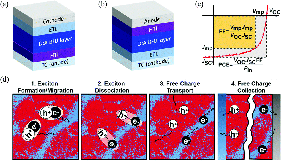 | ||
| Fig. 1 (a) Conventional and (b) inverted OSC architectures; (c) solar cell figures-of-merit: short circuit current density (JSC, mA cm−2), open circuit voltage (VOC, V), fill factor (FF) and PCE;42 and (d) working mechanism of the BHJ layer in OSCs (red and blue areas represent donor and acceptor domains, respectively).42 Reproduced from ref. 42 with permission from John Wiley and Sons, copyright 2019. | ||
The donor material in the active layer is a p-type semiconductor that has relatively high-lying highest occupied molecular orbital (EHOMO) and lowest unoccupied molecular orbital (ELUMO) energy levels, which can stabilize and transport the photogenerated holes. On the contrary, the acceptor material is an n-type semiconductor that has low EHOMO and ELUMO with respect to those of the donor material, which can stabilize and transport the photogenerated electrons. One or both of the donor and acceptor materials should strongly absorb sunlight.
The ultimate photovoltaic performance parameter of an OSC is the PCE or η, which is the percentage of electric energy generated by an OSC out of the total photo energy incident on the active layer conventionally under the standardized AM 1.5G solar spectrum with an intensity of 100 mW cm−2. As shown in Fig. 1c, the PCE is contributed by three factors, the short circuit current density (JSC, mA cm−2), open circuit voltage (VOC, V), and fill factor (FF), obtained from the current density–voltage (J–V) curve of an OSC based on the relationship PCE = (JSC × VOC × FF)/Pin, where Pin is the input power density (100 mW cm−2) of the light source under AM 1.5G conditions. The FF represents the ratio of the product of Jmp × Vmp (at the maximum power point on the J–V curve) over the product of JSC and VOC. The FF values are typically 0.5–0.7 for high-performing OSCs. Broader light absorption in the solar spectrum by the active layer increases JSC of the OSC; however, absorption of long wavelength (lower energy) photons results in a lower VOC. Therefore, it is preferred that an active layer absorbs the maximum number of photons in the low wavelength region of ∼400–925 nm (or energies of ∼3–1.34 eV) based on the Shockley–Queisser (S–Q) limit.43 The portion of sunlight with wavelengths longer than 925 nm can be effectively utilized by developing a tandem OSC with two or more OSC devices combined.44–47 Research into tandem OSCs has also attracted much attention, but faces numerous issues since deposition of an increased number of well-defined thin active layers and interlayers is very challenging and the charge transport in these multilayered devices is too complicated to control. Although tandem OSCs can achieve higher PCE intrinsically, single junction OSCs still perform better at the moment.
A typical OSC device undergoes photovoltaic processes as follows (Fig. 1d):48–50 (1) excitons (hole–electron pairs) are produced in the BHJ active layer (in the donor, the acceptor, or both phases) upon absorption of photons from sunlight; (2) the formed excitons diffuse towards the donor–acceptor (D–A) interfaces; (3) the excitons are dissociated into free holes and electrons at the D–A interfaces; and (4) the free holes and electrons travel through the donor and acceptor phases and are collected at the anode and cathode, respectively.
An OSC works through close collaboration of matching donor and acceptors. Fig. 2 illustrates the complex hierarchical relationships between the cell performance, properties, and the molecular and nano-/microstructures of polymer donor materials. Each of the cell performance parameters, JSC, VOC, or FF, is influenced by the photovoltaic processes and material properties, which are ultimately governed by the molecular structure of the polymer donor.
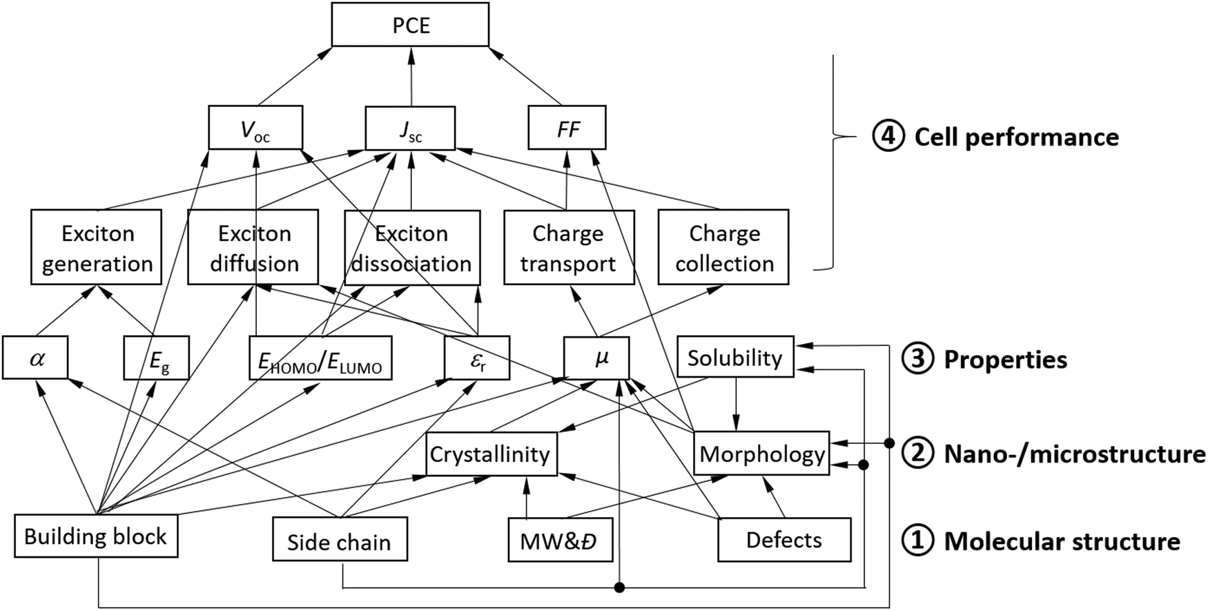 | ||
| Fig. 2 Scheme of the structure–property–cell performance relationships of a polymer donor for OSCs, where α is the absorption coefficient, εr is the dielectric constant (or relative permittivity), μ is the mobility, and MW and Đ are the molecular weight and its distribution, respectively, of the polymer donor. Defects may include terminal groups, homo coupled units in a copolymer, random arrangements of comonomers in a copolymer, regio-irregular units, branching, lightly cross-linked units, oligomers, etc. Some or all of these relationships may apply to small molecule donors as well as polymer and small molecule acceptors. | ||
Specifically, JSC is influenced by all the photovoltaic processes, where (1) the number of excitons generated (or photons absorbed) depends largely on the absorption coefficient (α) and the bandgap (Eg) of the donor; (2) exciton diffusion is influenced by the electronic structure of the conjugated building block, the dielectric constant (εr), and the morphology (phase size) of the donor; (3) exciton dissociation is influenced by the electronic structure of the building block, the dielectric constant, and the HOMO and LUMO energy offsets, ΔEHOMO and ΔELUMO, between the donor and the acceptor; and (4) transport and collection of charge carriers (holes) are determined by the hole mobility (μh) of the donor and its balance with the electron mobility (μe) of the acceptor. A higher dielectric constant can decrease the exciton binding energy, reducing exciton recombination events. If the donor phase is too large, excitons generated in a region with a distance to the donor and acceptor interface greater than the exciton diffusion length would recombine, leading to a reduction in JSC.
V OC is determined by the difference between ELUMO of the acceptor and EHOMO of the donor as well as the dielectric constant of the donor (and acceptor). A lower EHOMO of the donor helps achieve a high VOC, while a large dielectric constant can reduce the exciton binding energy, which would help reduce the required donor–acceptor energy offset ΔELUMO for exciton dissociation, achieving a higher VOC. Additionally, the type of building block (electronic structure) often plays a critical role in determining the minimal energy offset required for exciton dissociation, which is directly related to VOC.
The FF is critically influenced by μh of the donor and its balance with μe of the acceptor. High and balanced μh and μe of >10−4 cm2 V−1 s−1 are usually required to achieve a high FF. The morphology of the donor and acceptor blend film also exerts some influence on the FF.51–53 The carrier mobility is influenced by several factors including the building block, side chain, crystallinity (degree of crystallinity and crystal orientation), film morphology, and amount of structural defects. A face-on lamellar packing motif for the polymer donor in an OSC is desirable because the charge transport is facilitated through the vertically aligned π–π stacks in this type of crystal motif. Structural defects refer to the terminal groups, homo coupled units in a copolymer, random arrangements of comonomers in a copolymer, regio-irregular units, branching, lightly cross-linked units, oligomers, etc. Most structural defects are difficult to determine but are often largely responsible for the poor cell performance since they have adverse effects on the crystallinity, morphology, and charge transport.
Additionally, although not shown in Fig. 2, the properties of the interfaces between the active layer and the HTL and/or ETL determine the efficiency of charge collection, which influences JSC, VOC, and/or the FF.
As can be clearly seen in Fig. 2, the molecular structure fundamentally dictates the nano-/microstructure, properties, and OSC performance of a polymer donor. In particular, the π-conjugated building block used to construct a donor determines all the properties of the donor and the performance parameters of its OSC.
Characterization of the structures and properties of donors, acceptors, and their blends is nontrivial and often encounters great challenges. The widely used methodologies for characterization of their key structural features and properties are briefly described as follows:
(1) Eg: UV-vis-NIR spectroscopy is a simple and the most widely used method to obtain the bandgap of the donor or acceptor using the absorption onset wavelength. However, many materials, particularly polymers, are non-monodisperse and contain disordered structures, resulting in a tail in their absorption spectra with ill-defined onset edges. Measurements using the intersection of the normalized absorption and emission spectra can overcome this issue.54,55 Alternatively, Eg can be calculated from the onset of the EQE spectrum of the OSC device to minimize the influence of the film morphology.55
(2) EHOMO/ELUMO: due to its low-cost and easy operation, cyclic voltammetry (CV) is the most popular method used to estimate EHOMO and ELUMO of the donor or acceptor by using the onset oxidation and reduction potentials, respectively, with a reference having a known EHOMO such as ferrocene (EHOMO = −4.8 eV). However, most donors and acceptors only show the oxidation or the reduction process, respectively, in their CV diagrams. In such cases, the optical bandgap obtained by UV-vis-NIR and EHOMO or ELUMO obtained by CV are usually combined to calculate ELUMO or EHOMO of the donor or acceptor, respectively. The energy levels calculated in this way are often inaccurate because of the large exciton binding energy (up to ∼0.3–1 eV) associated with organic semiconductors. The energy levels determined by CV measurements also have large variations caused by different experimental conditions56,57 and thus the values reported for the same materials in the literature often vary largely. Nonetheless, the EHOMO and ELUMO values obtained by CV under similar conditions are still very useful and quite reliable for comparing the energy levels of different materials. A combination of ultraviolet photoelectron spectroscopy (UPS) and (low-energy) inverse photoemission spectroscopy (IPES), which are much more expensive and complex to operate compared to the electrochemical setup used for the CV measurements, can also be used to more accurately measure the ionization potential (IP) and electron affinity (EA) values, which correspond to EHOMO and ELUMO, respectively.56–58
(3) Crystallinity: wide-angle X-ray diffraction (WAXD) is the standard characterization method to study the crystal structure. When this method is used for thin films (∼100 nm), a grazing incidence geometry is used and the method is termed as GIWAXS or GIXD. GIWAXS can be used to obtain information about the structure, orientation, and ordering of crystallites.59 Particularly, two-dimensional (2-D) GIWAXS measured with a powerful synchrotron X-ray source can reveal the in-plane and out-of-plane crystal structures of the finely mixed BHJ blend film at the nanometer scale.60–62
(4) Morphology/phase separation: atomic force microscopy (AFM) is a surface analysis technique commonly used to probe morphological features (on the nanometer to micron-scale) such as film roughness, phase segregation, and domain size. Transmission electron microscopy (TEM) has also been used to extract information about phase segregation, grain size, and grain connectivity.59 Resonant soft X-ray scattering (RSoXS) is another evolving method to investigate multi-component, multi-phase systems like the active layer of an OSC, where the contrast of the donor and acceptor components can be tuned by selection of the incident X-ray energy to quantitatively reveal the molecular orientation, domain purity, and domain spacing.59,60,63,64
(5) Exciton dissociation, collection, and recombination: the trend of photocurrent density Jph (Jph = JL − JD, where JL is the current density under illumination and JD is the current density in the dark) versus effective voltage (Veff = V − V0) gives insights into the charge generation and exciton dissociation characteristics of the device. Here V0 is called the compensation voltage or the voltage at which Jph = 0 and V is the applied voltage.65,66Jph reaches a saturation value (Jsat) with increasing Veff, which means that all the photogenerated excitons are dissociated into free carriers and collected by the electrodes with the assistance of large reverse bias. Thus, the exciton dissociation probability, defined as Pdiss = JSC/Jsat, reflects the efficiency of exciton dissociation, charge transport, and charge collection.65 The photoinduced charge transfer efficiency (from the donor to the acceptor or vice versa) can also be probed via photoluminescence (PL) quenching and decay measurements of the blend films relative to the neat films.67,68
The light intensity dependence of VOC can directly indicate the role of trap-assisted recombination (or SRH recombination) versus bimolecular recombination under open circuit conditions. For this analysis the slope S1 (or ideality factor) is defined as 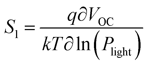 , where q is the elementary charge, k is the Boltzmann constant, T is the absolute temperature, and Plight is the light intensity.69–71 A value of S1 close to 1 indicates more ideal recombination, whereas values >1 indicate more trap-assisted/SRH recombination in the device.65,71 Moreover, JSC of an OSC follows a power law dependence with respect to the light intensity (Plight) (i.e.
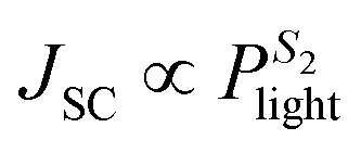 ), where S2 is the exponential factor. A value of S2 close to unity indicates negligible bimolecular recombination during sweep-out under short circuit conditions.72–74
(6) Mobility: the methods for measuring the carrier mobility along the direction vertical to the film (relevant to the charge transport in OSC devices) include space-charge-limited current (SCLC),75–77 time of flight (TOF),78,79 carrier extraction by linearly increasing voltage (CELIV),80,81 photogenerated charges in CELIV (photoCELIV),82–84 and impedance spectroscopy (IS).85,86 The SCLC method is most widely used.
(7) Dielectric constant: the exciton binding energy (Eb) estimated by the coulomb interaction depends inversely on the dielectric constant, εr: Eb = q2/4πε0εrr, where q is the elementary charge, ε0 is the permittivity of a vacuum, and r is the electron and hole separation distance.87–92 Therefore, to facilitate exciton diffusion and dissociation, semiconductors with high dielectric constant values are preferred. The capacitance–voltage (C–V) measurement at different frequencies (impedance spectroscopy) of a film sandwiched between two electrodes can be performed to obtain the dielectric constant value.93–98
3 High performance WBG polymer donors for NFAs
On the basis of the optical bandgap, polymer donors can be divided into narrow-bandgap or low-bandgap (LBG, bandgap <1.6 eV), medium-bandgap (MBG, 1.6 eV < bandgap < 1.8 eV) and wide-bandgap (WBG, bandgap >1.8 eV).35 To form complementary absorption with narrow-bandgap NFAs, polymer donors with medium- or wide-bandgaps are needed. Regioregular, head-to-tail poly(3-hexylthiophene-2,5-diyl) (P3HT), which can be synthesized at low cost and shows high μh, has been extensively studied as a donor for OSCs based on fullerene acceptors.50,99,100 However, P3HT has a rather high EHOMO (ca. −5.1 eV), which leads to a low VOC, limiting its solar cell performance.101–105 On the other hand, donor–acceptor (D–A) polymers containing alternating D and A building blocks on the backbone (Fig. 3) have been extensively developed as donor materials since their optical bandgaps and FMO (i.e. HOMO and LUMO) energy levels can be conveniently tuned through intramolecular charge transfer (ICT) by choosing different D and A units.32,35,49,106–108 D–A polymers also have enhanced μh due to intermolecular D–A interactions. D–A polymers have shown far better solar cell performances than P3HT in both fullerene and NFA-based OSCs.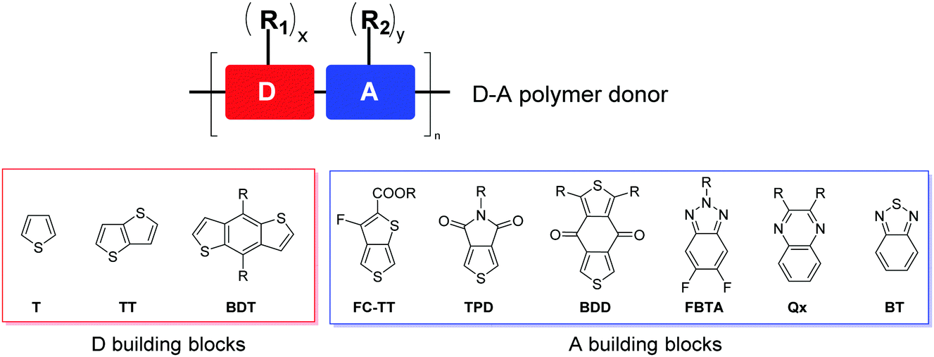 | ||
| Fig. 3 Chemical structures of representative D and A building blocks used for high performance D–A polymers, where R1 or R2 is a side chain chosen from alkyl, alkoxy, alkylthio, and aryl groups, etc., and x or y is an appropriate integer. | ||
The D building blocks mostly used to construct high-performing D–A polymer donors for NFA-based OSCs are thiophene-containing moieties such as thiophene (T), thieno[3,2-b]thiophene (TT), and benzo[1,2-b:4,5-b′]dithiophene (BDT) (Fig. 3), owing to their appropriate electron-donating effect to tune EHOMO, lower steric effect to maintain backbone coplanarity, rich chemistry, and good chemical stability. Two or more D blocks are often used to constitute a D unit in a D–A polymer. The frequently used A building blocks include 3-fluorothieno[3,4-b]thiophene-2-carboxylate (FC-TT),109 thieno[3.4-c]pyrrole-4,6-dione (TPD),110 benzo[1,2-c:4,5-c′]dithiophene-4,8-dione (BDD),111 difluorobenzotriazole (FBTA),112 quinoxaline (Qx),113 and benzothiadiazole (BT),114 which have an electron-withdrawing ester, imide, fluorine, diketone, and N-containing heterocycle substituting or fused to the thiophene or benzene ring. One or more linear or branched alkyl side chains (R1 and R2) are anchored to D, A, or both units to render the polymer soluble and control the packing of polymer chains in the solid state.
By analysing the chemical structures of high-performing D–A polymer donors, one would notice that the majority of them contain the fused ring structure BDT as the D building block. Therefore, in this review, the polymer donors are classified as BDT-based polymers and non-BDT based polymers. The BDT-based polymers are further classified according to the A units: (1) ester or imide substituted building blocks (FC-TT and TPD), (2) diketone derivatives (BDD), (3) N-heterocycles containing sp2 nitrogen (FBTA and Qx), and (4) other A units (such as BT) (Fig. 3).4,49,106,114 The structures of the polymer donors discussed in this review are shown in Fig. 4 and 5 based on this classification. Their key optoelectronic properties are listed in Table 1.
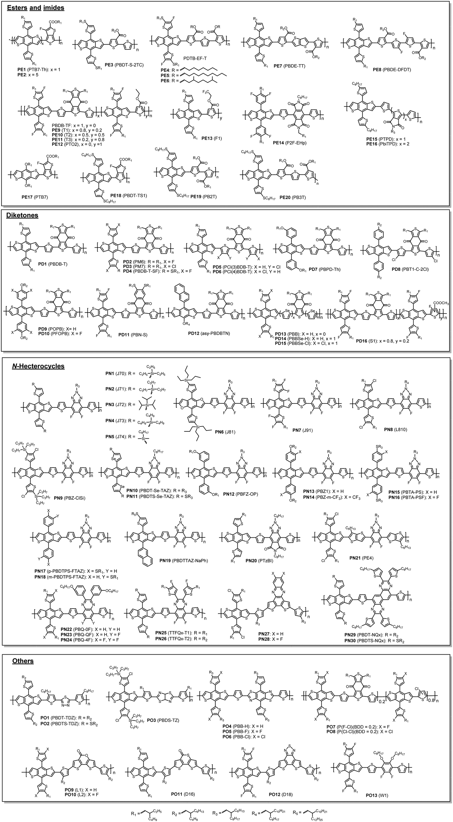 | ||
| Fig. 4 Chemical structures of BDT-based polymer donors discussed in this review. Their properties are listed in Table 1. Names in parentheses are used in the original publications. | ||
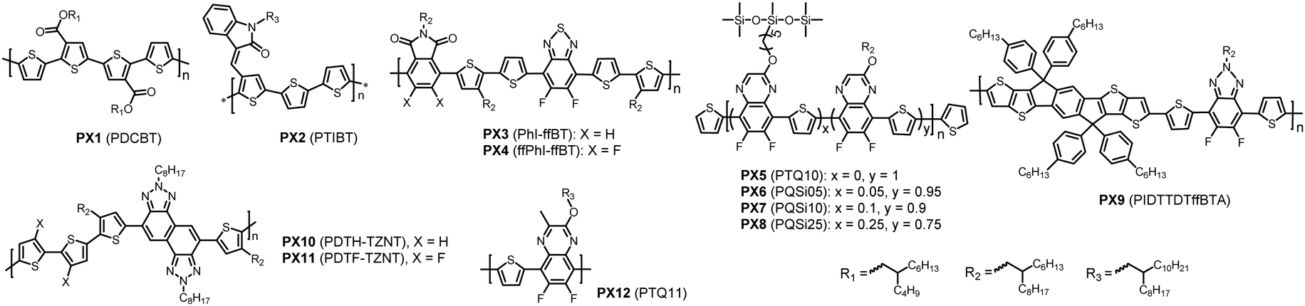 | ||
| Fig. 5 Chemical structures of non-BDT-based polymer donors discussed in this review. Their properties are listed in Table 2. Names in parentheses are used in the original publications. | ||
| Polymer | E HOMO (eV) | E LUMO (eV) | E gopt (eV) | λ max (nm) | λ onset (nm) | α f-max (×105 cm−1) | α s-max (×105 M−1 cm−1) | μ h (×10−4 cm2 V−1 s−1) | Ref. |
|---|---|---|---|---|---|---|---|---|---|
| a Obtained from film absorption, αf-max represents the maximum extinction coefficient in a thin film, and αs-max represents the maximum extinction coefficient in solution. b The numbers of significant digits of the data are adopted from the original references and may be different. | |||||||||
| PE1 | −5.22 | −3.64b | 1.58 | 625, 690 | 785 | 1.0b | 11.1115 | 8 | |
| PE2 | −5.37 | −3.63 | 1.74 | 549 | 711 | 116 | |||
| PE3 | −5.47 | −3.58 | 1.94 | 538 | 1b | 117 | |||
| PE4 | −5.51 | −3.59 | 1.93 | 540 | 642 | 0.79 | 1b | 118 | |
| PE5 | −5.50 | −3.59 | 1.93 | 544 | 642 | 0.81 | 1.2b | 118 | |
| PE6 | −5.54 | −3.6b | 1.94 | 536 | 639 | 0.72 | 0.73 | 118 | |
| PE7 | −5.49 | 1.97 | 538 | 629 | 0.726b | 0.607b | 1.11b | 119 | |
| PE8 | −5.5 | 1.94 | 544 | 639 | 0.758 | 0.65b | 3.4 | 119 | |
| PE9 | −5.48 | −3.63 | 1.83 | 678 | 120 | ||||
| PE10 | −5.51 | −3.63 | 1.87 | 663 | 120 | ||||
| PE11 | −5.55 | −3.62 | 1.93 | 642 | 120 | ||||
| PE12 | −5.59 | −3.67 | 1.99 | 533 | 623 | 0.769 | 121 | ||
| PE13 | −5.50 | −3.53 | 1.97 | 577 | 630 | 1.25 | 122 | ||
| PE14 | −5.46 | −3.13 | 1.82 | 700 | 123 | ||||
| PE15 | −5.05 | −3.19 | 1.86 | 562, 613 | 667 | 110 | |||
| PE16 | −5.20 | −3.45 | 1.78 | 586, 630 | 670 | 110 | |||
| PE17 | −5.157 | −3.317 | 1.60 | 614, 674 | 775 | 5.8 | 124 | ||
| PE18 | −5.33 | −3.52 | 1.51 | 655, 705 | 820 | 109125 | 126 | ||
| PE19 | −5.63 | −3.63 | 2.24 | 416 | 554 | 0.362 | 0.028 | 127 | |
| PE20 | −5.39 | −3.37 | 1.96 | 540 | 633 | 0.557 | 0.94 | 127 | |
| PD1 | −5.23 | −3.18 | 1.80 | 581, 622 | 689 | 0.86128 | 1.11128 | 111 | |
| PD2 | −5.50 | −3.56 | 1.80 | 570, 614 | 689 | 2.97 | 129 | ||
| PD3 | −5.52 | −3.57 | 1.79 | 577, 606128 | 692 | 0.99128 | 6.67128 | 130 | |
| PD4 | −5.40 | −3.60 | 1.80 | 626 | 688 | 1.08 | 22 | ||
| PD5 | −5.54 | −3.27 | 2.11 | 479 | 588 | 131 | |||
| PD6 | −5.48 | −3.47 | 1.78 | 622 | 697 | 131 | |||
| PD7 | −5.42 | −3.36 | 1.90 | 556 | 652 | 0.697 | 0.331 | 7.56132 | 133 |
| PD8 | −5.59 | −3.53 | 1.85 | 627 | 671 | 13.4 | 134 | ||
| PD9 | −5.38 | 3.57 | 1.81 | 577 | 685 | 0.531 | 3.96 | 135 | |
| PD10 | −5.5 | −3.64 | 1.86 | 612 | 667 | 0.845 | 15.1 | 135 | |
| PD11 | −5.48 | −3.52 | 1.75 | 632, 625 | 710 | 136 | |||
| PD12 | −5.41 | −3.58 | 1.83 | 621 | 678 | 1 | 137 | ||
| PD13 | −5.54 | −3.59 | 1.95 | 551 | 636 | 2.63 | 138 | ||
| PD14 | −5.16 | −3.45 | 1.71 | 657 | 726 | 5.54 | 138 | ||
| PD15 | −5.36 | −3.63 | 1.73 | 645 | 718 | 7.37 | 138 | ||
| PD16 | −5.52 | −3.72 | 1.80 | 689 | 139 | ||||
| PN1 | −5.37 | −2.91 | 1.99 | 538, 580 | 623 | 0.89 | 140 | ||
| PN2 | −5.40 | −3.24 | 1.96 | 528, 573 | 633 | 0.96 | 141 | ||
| PN3 | −5.42 | −3.29 | 1.98 | 533, 578 | 626 | 0.7 | 140 | ||
| PN4 | −5.46 | −2.92 | 1.98 | 535, 576 | 626 | 0.69 | 140 | ||
| PN5 | −5.56 | −3.06 | 1.99 | 526 | 623 | 0.68 | 140 | ||
| PN6 | −5.42 | −2.93 | 1.93 | 553, 600 | 642 | 142 | |||
| PN7 | −5.50 | −3.02 | 2.00 | 536 | 620 | 0.98 | 143 | ||
| PN8 | −5.57 | −3.58 | 1.99 | 622 | 0.838 | 144 | |||
| PN9 | −5.56 | −3.50 | 1.94 | 536 | 640 | 1.08 | 10.2 | 145 | |
| PN10 | −5.23 | −3.43 | 1.92 | 372, 550, 597 | 646 | 0.564 | 146 | ||
| PN11 | −5.29 | −3.49 | 1.9 | 374, 550, 602 | 653 | 0.854 | 146 | ||
| PN12 | −5.33 | −3.01 | 1.99 | 530, 575 | 623 | 7.28 | 147 | ||
| PN13 | −5.27 | −3.06 | 1.96 | 539 | 632 | 0.523 | 7.23 | 148 | |
| PN14 | −5.49 | −3.22 | 1.99 | 533 | 623 | 0.651 | 7.86 | 148 | |
| PN15 | −5.34 | −3.4 | 1.94 | 639 | 0.73 | 5.59 | 20 | ||
| PN16 | −5.52 | −3.54 | 1.98 | 537, 577 | 626 | 0.7 | 6.01 | 20 | |
| PN17 | −5.32 | −3.36 | 1.96 | 544, 589 | 633 | 0.62 | 149 | ||
| PN18 | −5.40 | −3.40 | 2.00 | 542, 579 | 621 | 0.60 | 149 | ||
| PN19 | −5.44 | −3.49 | 1.95 | 636 | 150 | ||||
| PN20 | −5.34 | −3.46 | 1.81 | 600 | 685 | 0.7 | 151 | ||
| PN21 | −5.42 | −3.49 | 1.93 | 590 | 642 | 1.1 | 152 | ||
| PN22 | −5.18 | −3.48 | 1.70 | 636 | 755 | 0.545 | 0.454 | 113 | |
| PN23 | −5.34 | −3.62 | 1.72 | 600 | 737 | 0.731 | 0.515 | 113 | |
| PN24 | −5.49 | −3.7 | 1.79 | 583 | 716 | 0.859 | 0.617 | 113 | |
| PN25 | −5.31 | −3.62 | 1.69 | 361, 435, 652 | 736 | 4.73 | 153 | ||
| PN26 | −5.38 | −3.67 | 1.71 | 361, 443, 635 | 724 | 4.64 | 153 | ||
| PN27 | −5.33 | −2.94 | 1.86 | 667 | 2.00 | 154 | |||
| PN28 | −5.46 | −3.16 | 1.79 | 693 | 7.74 | 154 | |||
| PN29 | −5.24 | −3.42 | 1.80 | 374, 450, 632 | 689 | 29 | 155 | ||
| PN30 | −5.31 | −3.46 | 1.81 | 368, 452, 636 | 685 | 34.5 | 155 | ||
| PO1 | −5.35 | −2.78 | 2.07 | 599 | 25 | 156 | |||
| PO2 | −5.39 | −2.79 | 2.09 | 593 | 31 | 156 | |||
| PO3 | −5.41 | −3.46 | 1.95 | 550 | 636 | 1.13 | 157 | ||
| PO4 | −5.47 | −3.47 | 2.00 | 580 | 620 | 1.53 | 0.614 | 158 | |
| PO5 | −5.47 | −3.57 | 2.00 | 579 | 620 | 1.39 | 0.143 | 158 | |
| PO6 | −5.64 | −3.64 | 2.00 | 580 | 620 | 1.27 | 0.27 | 158 | |
| PO7 | −5.62 | −3.74 | 1.88 | 361, 565 | 660 | 0.896 | 159 | ||
| PO8 | −5.67 | −3.77 | 1.90 | 364, 565 | 653 | 0.944 | 159 | ||
| PO9 | −5.45 | −2.79 | 1.96 | 634 | 7.20160 | 161 | |||
| PO10 | −5.52 | −2.91 | 1.96 | 634 | 161 | ||||
| PO11 | −5.48 | −2.83 | 1.95 | 551, 588 | 636 | 11.9 | 160 | ||
| PO12 | −5.51 | −2.77 | 1.98 | 584, 559 | 626 | 15.9 | 10 | ||
| PO13 | −5.36 | −2.81 | 2.16 | 502, 535 | 574 | 162 | |||
| PX1 | −5.31 | −3.00 | 1.90 | 551 | 653 | 1.05 | 163 and 164 | ||
| PX2 | −5.41 | −3.61 | 1.80 | 576 | 689 | 165 | |||
| PX3 | −5.55 | −3.80 | 1.75 | 583 | 708 | 166 | |||
| PX4 | −5.63 | −3.86 | 1.77 | 580 | 700 | 166 | |||
| PX5 | −5.54 | −2.98 | 1.92 | 646 | 167 | ||||
| PX6 | −5.67 | −3.74 | 1.93 | 642 | 168 | ||||
| PX7 | −5.62 | −3.71 | 1.92 | 646 | 168 | ||||
| PX8 | −5.61 | −3.69 | 1.92 | 646 | 168 | ||||
| PX9 | −5.25 | −3.63 | 2.02 | 583 | 627 | 0.818 | 1.2 | 169 | |
| PX10 | −5.16 | −3.10 | 1.94 | 541 | 639 | 0.804 | 170 | ||
| PX11 | 5.24 | −3.23 | 1.84 | 559, 617 | 674 | 1.28 | 170 | ||
| PX12 | −5.52 | −2.76 | 1.95 | 637 | 171 | ||||
As mentioned in the previous section, good matching between donor and acceptor materials is vital for achieving high OSC performance. Therefore, developing a polymer donor material having its photophysical properties matching with those of a certain NFA material on purpose is the most adopted and effective strategy. From a large number of high performance NFAs,36–38,40 we deliberately select the three most representative ones, ITIC, IT-4F, and Y6, which have been widely used for developing ultrahigh performance (PCE >10%) polymer donors. Their chemical structures are shown in Fig. 6, while their key optoelectronic properties are summarized in Table 2. It should be noted that the reported ELUMO and EHOMO values of the three NFAs, particularly ITIC, vary largely in the literature due to the different measurement conditions as mentioned earlier.
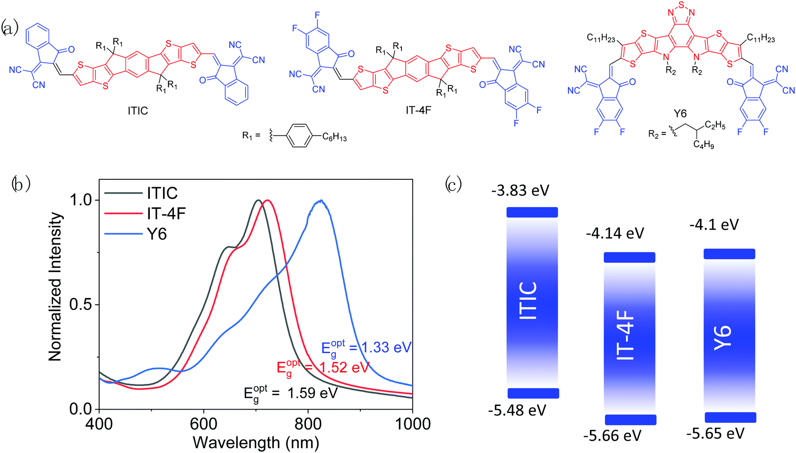 | ||
| Fig. 6 Chemical structures (a), thin-film UV-vis-NIR spectra (b), and energy diagrams (c) of ITIC, ITIC-4F, and Y6. | ||
| NFA | E HOMO (eV) | E LUMO (eV) | E gopt (eV) | λ max (nm) | λ onset (nm) | α f-max (×105 cm−1) | α s-max (×105 M−1 cm−1) | μ e (×10−4 cm2 V−1 s−1) | Ref. |
|---|---|---|---|---|---|---|---|---|---|
| a Obtained from film absorption. b SCLC mobility obtained at the annealing temperature shown in brackets. | |||||||||
| ITIC | −5.48 | −3.83 | 1.59 | 702 | 780 | 1.10 | 1.72 | 3 (150 °C) | 8 |
| −5.60 | −3.85 | 172 | |||||||
| −5.64 | −4.04 | 173 | |||||||
| −5.70 | −4.00 | 174 | |||||||
| IT-4F | −5.66 | −4.14 | 1.52 | 726 | 803 | 1.16 | 2.10 | 5.05 (150 °C) | 22 |
| −5.71 | −4.15 | 175 | |||||||
| −5.69 | −4.17 | 176 | |||||||
| Y6 | −5.65 | −4.10 | 1.33 | 821 | 931 | 1.07 | 2.39 | 2.35 (100 °C), 14.8 (150 °C), 33.0 (200 °C) | 9 |
| −5.70 | −4.08 | 177 | |||||||
| −5.60 | −4.10 | 130 | |||||||
| −5.65 | −4.11 | 175 | |||||||
3.1 High performance polymer donors matching with ITIC
As a milestone for NFAs, ITIC was developed in 2015 by Lin et al.,8 which has an electron-donating indacenodithienothiophene (IDTT) central unit and two electron-withdrawing 2-methylene-(3-(1,1-dicyanomethylene)-indanone) (IC) end groups. Hexyl phenyl side chains are introduced on IDTT to render the material soluble and to suppress the excessive aggregation of molecules in the solid state. ITIC has a good SCLC μe of 3.0 × 10⁻⁴ cm2 V−1 s−1, which approaches that of fullerene-based acceptors (∼10−4–10−2 cm2 V−1 s−1).179,180 Its rather high ELUMO (−3.83 eV) helps achieve a high VOC. However, ITIC has a relatively large bandgap (Eg = 1.59 eV), absorbing sunlight below 800 nm, which restricts JSC when a WBG polymer donor is used. Nonetheless, ITIC has been widely used as a model acceptor for the study and development of various polymer donors to provide significant insights into their structure–property–cell performance relationships.![[thin space (1/6-em)]](https://www.rsc.org/images/entities/char_2009.gif) :1 has the optimal EHOMO of −5.37 eV and Eg of 1.74 eV to form complementary absorption with ITIC. As a result, a higher JSC (17.24 mA cm−2) along with a higher VOC (0.89 V) and FF (67%) and thus a higher PCE of 10.27% were achieved compared to polymers with other D/A ratios. An et al.117 developed a polymer PE3 (PBDT-S-2TC) having a weaker electron-withdrawing ester substituted thiophene as A units. A non-substituted thiophene spacer was inserted between the ester substituted thiophene and the BDT unit to maintain the planarity of the polymer backbone. In addition, alkylthio chains were introduced onto BDT to lower EHOMO (−5.47 eV). A wide bandgap of 1.94 eV was obtained, which matches that of ITIC very well for complementary light absorption. The devices based on PE3:ITIC showed an improved JSC and a very high VOC of 0.96 V, resulting in a PCE of 10.12%.
:1 has the optimal EHOMO of −5.37 eV and Eg of 1.74 eV to form complementary absorption with ITIC. As a result, a higher JSC (17.24 mA cm−2) along with a higher VOC (0.89 V) and FF (67%) and thus a higher PCE of 10.27% were achieved compared to polymers with other D/A ratios. An et al.117 developed a polymer PE3 (PBDT-S-2TC) having a weaker electron-withdrawing ester substituted thiophene as A units. A non-substituted thiophene spacer was inserted between the ester substituted thiophene and the BDT unit to maintain the planarity of the polymer backbone. In addition, alkylthio chains were introduced onto BDT to lower EHOMO (−5.47 eV). A wide bandgap of 1.94 eV was obtained, which matches that of ITIC very well for complementary light absorption. The devices based on PE3:ITIC showed an improved JSC and a very high VOC of 0.96 V, resulting in a PCE of 10.12%.
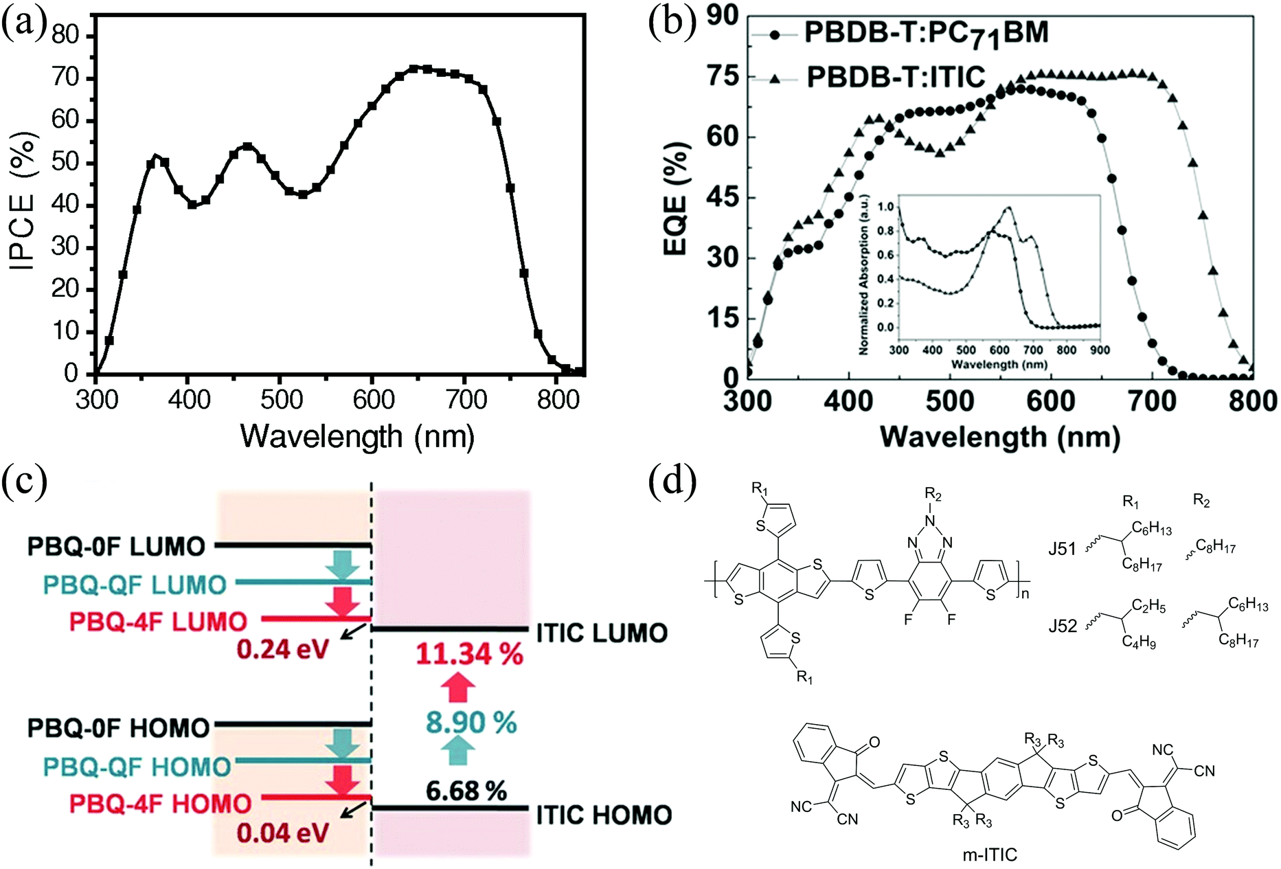 | ||
| Fig. 7 (a) IPCE spectrum of the PE1:ITIC-based OSC, reproduced from ref. 8 with permission from John Wiley and Sons, copyright 2015; (b) EQE curve of the PD1:ITIC-based OSC, reproduced with permission,16 copyright 2016, John Wiley and Sons; (c) energy level schematic of PN22, PN23, PN24, and ITIC, reproduced from ref. 113 with permission from John Wiley and Sons, copyright 2016; and (d) chemical structures of J51, J52 and m-ITIC. | ||
| Blend | μ h, μe (× 10−4 cm2 V−1 s−1), μe(h)/μh(e)a | EQEb (%) | V OC (V) | J SC (mA cm−2) | FF (%) | PCE (%) | S 1 | S 2 | P diss (%) | Ref. |
|---|---|---|---|---|---|---|---|---|---|---|
|
a
μ
e/μh or μh/μe, whichever is >1.
b Maximum value of EQE.
c Obtained from VOC ∼ S1log(Plight).
d Obtained from Jph ∼ S2log(Plight).
e The numbers of significant digits of the data are adopted from the original references and may be different.
|
||||||||||
| PE1:ITIC | 0.43, 1.1, 2.63 | 72.6e | 0.81e | 14.21e | 59.1e | 6.8e | 8 | |||
| PE2:ITIC | 0.298, 0.346, 1.16 | 0.89 | 17.24 | 67e | 10.27e | 1.15 | 0.927 | 116 | ||
| PE3:ITIC | 2.11, 2.83, 1.34 | 0.96 | 16.4e | 64.3 | 10.12 | 117 | ||||
| PD1:ITIC | 2.1, 3.13, 1.49 | 0.899e | 16.81 | 74.2 | 11.21 | 16 | ||||
| PD7:ITIC | 2.59, 2.25, 1.15 | 79e | 1.01 | 18.1 | 59 | 10.8 | 1.01 | 86.8e | 133 | |
| PD12:ITIC | 2.91, 2.67, 1.09 | 76 | 0.942 | 16.81 | 66.3 | 10.5 | 137 | |||
| PN2:ITIC | 3.78, 3.07, 1.23 | 76.5 | 0.94 | 17.32 | 69.77e | 11.41 | 141 | |||
| PN1:m-ITIC | 1.93, 8.4, 4.34 | 81.5 | 0.92 | 18.09 | 69.82 | 11.62 | 140 | |||
| PN2:m-ITIC | 1.09, 4.66, 4.28 | 0.944 | 18.09 | 70.59 | 12.05 | 140 | ||||
| PN3:m-ITIC | 0.46, 3.77, 8.2 | 0.962 | 16.35 | 65.03 | 10.23 | 140 | ||||
| PN4:m-ITIC | 0.38, 3.12, 8.2 | 0.974 | 16.45 | 66.87 | 10.71 | 140 | ||||
| PN5:m-ITIC | 0.24, 4.0, 16.66 | 0.99 | 15.89 | 61.18 | 9.63 | 140 | ||||
| PN6:ITIC | 3.66, 4.06, 1.11 | 0.95 | 15.27 | 73.08 | 10.6 | 0.94e | 96e | 142 | ||
| PN6:m-ITIC | 4.08, 4.67, 1.15 | 0.96 | 16.48 | 69.83 | 11.05 | 1.01 | 97 | 142 | ||
| PN7:m-ITIC | 1.016, 3.002, 2.95 | 0.984 | 18.03 | 65.54 | 11.63 | 1.028e | 143 | |||
| PN10:ITIC | 13.3, 8.7, 1.53 | 78 | 0.81 | 18.63 | 66.7 | 10.07 | 146 | |||
| PN11:ITIC | 24.7, 20.3, 1.22 | 80 | 0.84 | 19.51 | 75.1 | 12.31 | 146 | |||
| PN12:ITIC | 3.25, 2.62, 1.24 | 82 | 0.91 | 18.7 | 61.8 | 10.5 | 1.26 | 0.94 | 147 | |
| PN13:ITIC | 4.36, 2.98. 1.46 | 72 | 0.74 | 15.7 | 49.8 | 5.8 | 1.8 | 0.93 | 148 | |
| PN14:ITIC | 5.08, 3.96, 1.28 | 84 | 0.94 | 18.4 | 60.2 | 10.4 | 1.32 | 0.99 | 148 | |
| PN15:ITIC | 4.94, 3.81, 1.3 | 0.94 | 18.23 | 69.19 | 11.85 | 0.93 | 93 | 20 | ||
| PN16:ITIC | 5.46, 5.25 1.04 | 1.01 | 18.51 | 74.4 | 13.91 | 0.97 | 95.4 | 20 | ||
| PN17:ITIC | 1.15, 3.93, 3.42 | 0.89 | 18.12 | 67.37 | 10.86 | 0.92 | 93 | 149 | ||
| PN18:ITIC | 4.16, 3.16, 1.32 | 0.95 | 18.76 | 73.85 | 13.16 | 0.96 | 95 | 149 | ||
| PN19:ITIC | 2.132, 3.397, 1.59 | 83 | 0.936 | 18.21 | 67.8 | 11.56 | 150 | |||
| PN20:ITIC | 0.86, 0.23, 3.74 | 0.87 | 18.29 | 64.34 | 10.24 | 0.971 | 178 | |||
| PN22:ITIC | 7.8, 8.2, 1.05 | 0.69 | 16.16 | 59.91 | 6.68 | 1.33 | 0.952 | 88 | 113 | |
| PN23:ITIC | 8.6, 8.3, 1.04 | 0.83 | 17.16 | 62.49 | 8.9 | 1.23 | 0.981 | 95 | 113 | |
| PN24:ITIC | 10, 10, 1 | 0.95 | 17.87 | 66.8 | 11.34 | 113 | ||||
| PN25:ITIC | 1.13, 1.6, 1.42 | 75 | 0.9 | 16.88 | 69.24 | 10.52 | 0.96 | 97.2 | 153 | |
| PN26:ITIC | 0.139, 0.68, 4.89 | 66.4 | 0.94 | 13.75 | 56.11 | 7.22 | 0.9 | 96.3 | 153 | |
| PN29:ITIC | 1.8, 0.56, 3.2 | 71 | 0.87 | 16.21 | 64.6 | 9.11 | 1.37 | 0.92 | 89 | 155 |
| PN30:ITIC | 2.5, 1.3, 1.9 | 78 | 0.92 | 17.86 | 69.8 | 11.47 | 1.25 | 0.96 | 94 | 155 |
| PO1:ITIC | 8.5, 6.8, 1.25 | 1.01 | 17.15 | 67.7 | 11.72 | 156 | ||||
| PO2:ITIC | 12, 7.2, 1.67 | 1.1 | 17.78 | 65.4 | 12.8 | 156 | ||||
| P3HT:ITIC | 1.4, 1.68, 1.2 | 0.52 | 4.22 | 56.93 | 1.25 | 1.14 | 0.99 | 92 | 163 | |
| PX1:ITIC | 2.4, 16.3. 6.79 | 75 | 0.94 | 16.5 | 65.67 | 10.16 | 163 | |||
| PX2:ITIC | 1.79, 1.20, 1.49 | 72.5 | 0.66 | 15.19 | 57 | 5.72 | 165 | |||
Since then, PD1 was widely used as a star polymer donor and the PCE of devices based on PD1 was further improved to above 13% with a largely improved JSC of up to ∼20 mA cm−2 through rational design of new NFAs with narrower bandgaps.181–185
Fan et al.133 synthesized a novel polymer donor PD7 (PBPD-Th) with a low-lying EHOMO of −5.42 eV by replacing the 5-alkylthienyl in PD1 with m-alkoxyphenyl on the BDT units. OSCs based on PD7:ITIC have a smaller Eloss and therefore achieved a high VOC of up to 1.01 V. Moreover, the polymer also has a wide bandgap of 1.90 eV, resulting in complementary absorption with ITIC. High EQE values (up to ∼80%), especially in the short wavelength range (400–550 nm, ∼70% on average), were obtained, which led to a high JSC (18.1 mA cm−2) and thus a high PCE of 10.8%.
By breaking the symmetry of the BDT unit, i.e., introducing different side chains on two sides of BDT, Li et al.137 developed an asymmetric polymer donor PD12 (asy-PBDBTN). Alkoxyl side chains were introduced to modulate the absorption spectra and solubility of the polymers (achieving enhanced light-harvesting ability and compatibility with acceptor materials, simultaneously), while a β-position linked naphthalene unit with high ionization potential and low electron density was introduced to lower EHOMO. PD12 showed a low-lying EHOMO of −5.41 eV, a wide bandgap of 1.83 eV, and high light-harvesting ability with an αf-max of up to 1 × 105 cm−1. OSCs based on the PD12:ITIC blend displayed a high PCE of 10.5%.137
mA cm−2, a VOC of 0.94 V, and a FF of 69.77%, resulting in a high PCE of 11.41%. The annealed blend film showed high and balanced μh and μe of 3.78 × 10⁻⁴cm2 V−1 s−1 and 3.07 × 10⁻⁴ cm2 V−1 s−1, respectively, which contributed to the high JSC and high FF. It should be noted that ΔEHOMO between PN2 and ITIC is only 0.11 eV, which suggests a high hole transfer efficiency from the acceptor to the donor.
The same research group systemically investigated the effects of the size and configuration of side chains (PN1–PN5 (J70–J74)) on the OSC performance of their blends with an ITIC isomer, m-ITIC (Fig. 7d), which has meta-alkyl-phenyl substitution and shows a higher degree of self-organization and crystallinity.140 Among these five polymers, they found that the film absorption coefficients and hole mobilities decreased, while the EHOMO values downshifted, with increasing length and complexity (linear to branched) of the alkyl substituents, which resulted in decreased JSC and FF, but enhanced VOC. Among this series of polymers, PN2 showed the highest PCE of 12.05%.
When the thiophene rings in the BDT units were replaced with furan rings to form benzo[1,2-b:4,5-b′]difuran (BDF), the resultant polymer PN6 (J81), which is analogous to PN1, showed a lower EHOMO of −5.42 eV, achieving a high PCE of 11.05% when paired with m-ITIC.142 On the other hand, when the thiophene side chains on the BDT units in PN1 were di-substituted with electron-withdrawing fluorine atoms, the formed PN7 (J91) exhibited a further down-shifted EHOMO (−5.50 eV).143 OSCs based on PN7:m-ITIC showed an even higher PCE of 11.63%, resulting from the increased VOC and JSC.
Compared with thiophene, selenophene shows lower aromaticity and enhanced ground-state quinoid resonance character, which would result in improved planarity, increased effective conjugation length, and a lowered bandgap of the polymer. In addition, improved interchain interactions and charge carrier transport could also be observed for selenophene-containing polymers because of the stronger heteroaromatic interactions induced by selenium atoms.189,190
When the thiophene side chains on BDT units of J51 (Fig. 7d)18 were replaced with selenophene side chains, the obtained PN10 (PBDT-Se-TAZ) exhibited similar EHOMO (−5.23 vs. −5.26 eV) and Eg (1.92 vs. 1.91 eV) to those of J51.146 However, the PN10:ITIC blend showed much higher μh and μe of 13.3 × 10⁻⁴ cm2 V−1 s−1/8.7 × 10−4 cm2 V−1 s−1 compared to J51 (4.32 × 10⁻⁴ cm2 V−1 s−1/3.74 × 10−4 cm2 V−1 s−1), indicating much improved charge transport in PN10 due to the presence of selenophene side chains. Consequently, the devices based on PN10:ITIC showed improved performance (JSC = 18.63 mA cm−2; VOC = 0.81 V; FF = 66.7%; and PCE = 10.07%) compared to the devices based on J51:ITIC (JSC = 16.47 mA cm−2; VOC = 0.82 V; FF = 0.69; and PCE = 9.26%). Once the alkyl selenophene side chains in PN10 were changed to alkylthio selenophene side chains, the resulting PN11 (PBDTS-Se-TAZ) showed a slightly lower EHOMO (−5.29 vs. −5.23 eV), a slightly narrower Eg (1.90 vs. 1.92 eV), and a higher αs-max (the maximum extinction coefficient in solution) (8.54 × 10⁴vs. 5.64 × 10⁴ M−1 cm−1) compared to PN10.146 The PN11:ITIC blend showed greatly enhanced and more balanced μh and μe (2.47 × 10⁻³ cm2 V−1 s−1/2.03 × 10−3 cm2 V−1 s−1), and thus less recombination and higher exciton dissociation and charge collection efficiencies (Table 3). Therefore, PN11:ITIC displayed higher VOC (0.84 V), JSC (19.51 mA cm−2), FF (75.1%), and PCE (12.31%).146
Replacing thiophene side chains on BDT units with benzene side chains is a strategy to lower EHOMO as mentioned previously (in the case of PD7). Li et al.147 synthesized PN12 (PBFZ-OP) based on meta-alkoxy-phenyl-substituted BDT (BDT-m-OP) and FBTA units. EHOMO was lowered to −5.33 eV compared with J52 with thiophene side chains (EHOMO = −5.21 eV).19PN12 also showed a wider bandgap of 1.99 eV than that of J52 (1.96 eV), which could form a more complementary absorption profile when paired with ITIC. Much improved cell performance (VOC = 0.91 V; JSC = 18.7 mA cm−2; FF = 0.618; and PCE = 10.50%) was obtained for the PN12:ITIC blend compared with the J52:ITIC blend (VOC = 0.73 V; JSC = 13.1 mA cm−2; FF = 0.578; and PCE = 5.50%).
Later, the same group changed the alkoxy substituent of the phenyl side chains on BDT from the meta to the para position (PN13 (PBZ1)) and introduced a CF3 group on the meta position (PN14 (PBZ-m-CF3)) to further lower EHOMO.148 Compared with PN12, both polymers showed a similar bandgap (1.96 eV for PN13 and 1.99 eV for PN14). PN13 showed a slightly higher EHOMO of −5.27 eV, while PN14 showed a much lower EHOMO of −5.49 eV. Between these two polymers, PN14 exhibited a higher αf-max (6.51 × 10⁴vs. 5.23 × 104 cm−1), smaller π–π distance (3.60 vs. 3.69 Å), and slightly higher μh (7.86 × 10⁻⁴vs. 7.23 × 10⁻⁴ cm2 V−1 s−1). The PN14:ITIC blend showed a much higher PCE of 10.4% than PN13:ITIC (5.8%).
Li et al.20 synthesized another similar pair of polymers, using p-alkylthiophenyl without or with fluorine at the meta position as the side chains to BDT units, PN15 (PBTA-PS) and PN16 (PBTA-PSF), respectively. A wider bandgap of 1.98 eV and a much lower EHOMO of −5.52 eV were obtained for PN16 compared to PN15 (Eg = 1.94 eV; and EHOMO = −5.34 eV). When paired with ITIC, both showed a high VOC of ∼1 V and high JSC of ∼18 mA cm−2. The device based on PN16:ITIC showed a much improved FF of 74.4% (vs. 69.19% for PN15:ITIC) due to its higher and more balanced μh and μe, less recombination and higher exciton dissociation and charge collection efficiencies (Table 3). Therefore, while PN15:ITIC showed a PCE of 11.85%, the PN16:ITIC blend exhibited a much higher PCE of 13.91%, which is the highest value achieved among ITIC-based OSCs by far. The results indicate that alkylthiophenyl substitution on BDT is very beneficial for the improvement of the OSC performance of the resulting polymer. On other hand, fluorination on the phenyl ring could further enhance the cell performance.
Chen et al.149 conducted a further study to compare the effects of the position of alkylthio chains on phenyl (para or meta) on the OSC performance of this type of polymers. Compared with the polymer with alkylthio chains at the para position (PN17 (p-PBDTPS-FTAZ)), the one with the chains at the meta position, PN18 (m-PBDTPS-FTAZ), showed a lower EHOMO and blue-shifted absorption. When blended with ITIC, higher and more balanced μh and μe, less recombination, and higher exciton dissociation and charge collection efficiencies were observed. As a result, a higher PCE of 13.16% was achieved for the PN18:ITIC blend compared to PN17:ITIC (10.86%).
Liu et al.150 developed a series of polymer donors having the BDT unit asymmetrically substituted with an alkylthiolthienyl group on one side and a phenyl and naphthyl (or p-biphenyl) on the other. It was found that the long alkylthiolthienyl substituent can lower EHOMO, broaden the absorption spectrum, and improve the solubility. The non-substituted rigid aryl substituent (benzene, naphthalene and p-biphenyl) can be regarded as a lever arm to disturb the ITIC phase and weaken the polymer chain entanglements, which helps realize a favorable morphology even without post-treatment. When the polymer with the naphthyl substituent, PN19 (PBDTTAZ-NaPh), was blended with ITIC, the obtained film exhibited a homogeneous morphology with finely separated domains. A high PCE of 11.56% was obtained with this blend film.
Fan et al.151 used alkylimide to replace the two fluorine atoms on benzotriazole in FBTA to form an acceptor unit, TZBI, which was used to make a copolymer PN20 (PTZBI) with BDT. PN20 possesses a more delocalized electron distribution across the conjugated backbone, which lowers EHOMO and enhances the carrier mobility. A high PCE of 10.24% was obtained with the PN20:ITIC blend.178
Qx is another moderate electron-accepting N-heterocylic building block that is widely used in constructing WBG conjugated D–A polymer donors for OSCs.34,191 Zheng et al.113 conducted a systematic study on the correlations between the energy level alignment, performance, and device physics by finely tuning the FMO energy levels through introducing different numbers of F atoms. Three polymers with 0, 2 and 4 F atoms in one repeat unit, PN22 (PBQ-0F), PN23 (PBQ-QF) and PN24 (PBQ-4F), respectively, were synthesized. With an increasing number of F atoms, ELUMO and EHOMO downshifted gradually. PN24 showed the lowest EHOMO of −5.49 eV, and so achieved the highest VOC of 0.95 V when blended with ITIC. It should be noted that although the energy offsets between PN24 and ITIC are very small (ΔEHOMO = 0.04 eV and ΔELUMO = 0.24 eV), the devices exhibited efficient charge generation, which is an outstanding advantage over fullerene-based OSCs, which require a large energy offset of >0.3 eV for efficient exciton dissociation.87,121,192–195 A high JSC (17.87 mA cm−2) and FF (66.80%) were also obtained owing to the stronger inter-chain interaction, resulting in higher carrier mobility. Therefore, this blend afforded a high PCE of 11.34%. A mixture of non-halogenated solvents THF and IPA was used for processing the active layer, demonstrating the potential for environment-friendly fabrication of OSCs.
The thiophene donor building block possesses higher electron density and smaller steric hindrance, providing better absorption and charge transport to the resulting polymer than the benzene building block. Xu et al.153 replaced the phenyl side chains of Qx units with alkyl substituted fluorothiophene and introduced alkyl chains with different lengths on BDT units to form polymers PN25 (TTFQx-T1) and PN26 (TTFQx-T2). When paired with ITIC, the blend based on PN25 with short alkyl chains on BDT showed higher and more balanced μh and μe, less recombination, and higher exciton dissociation and charge collection efficiencies (Table 3). Therefore, it exhibited a much improved JSC (16.88 vs. 13.75 mA cm−2) and FF (69.24% vs. 56.11%) and thus a higher PCE (10.52% vs. 7.22%) compared with the PN26:ITIC blend. This result indicated that the alkyl chain length has notable influences on the photovoltaic properties.
Building blocks with an enlarged planar aromatic structure are favorable for ordered molecular packing and thus improved photovoltaic performance.196,197 In addition, alkylthiothiophene side chains can further reduce EHOMO. Based on these principles, Yu et al.155 used quinoxalino[6,5-f]quinoxaline (NQx) as A units and introduced alkylthiophene and alkylthiothiophene as side chains of BDT units to form PN29 (PBDT-NQx) and PN30 (PBDTS-NQx), respectively. The latter showed a lower EHOMO (−5.31 vs. −5.24 eV) and higher αs-max (3.45 × 10⁶vs. 2.9 × 10⁶ M−1 cm−1). The devices based on PN30:ITIC showed a higher PCE of 11.47% than those based on PN29:ITIC (9.11%).
The primary driving force for OSC research is the potential of manufacturing OSC products at a much lower cost than Si solar cells. The synthetic complexity (SC), which considers the number of reaction steps, purification methods, reaction yields, use of hazardous materials, etc., can be used to estimate the synthetic cost of the materials.199 Although BDT-based polymers showed high cell performance, the tedious synthesis of the BDT tin monomer alone would result in a high SC (>30%). P3HT can be synthesized with a very low SC (7.75%), but its OSC performance is rather low mainly due to its high EHOMO. To overcome the disadvantageous high-lying EHOMO of P3HT, Zhang et al.163 introduced electron-withdrawing carboxylate substituents on half of the thiophene rings in the backbone of polythiophene to form PX1 (PDCBT). EHOMO of PX1 down-shifted to −5.26 eV, much lower than that of P3HT (∼−5.0 eV). Therefore, a much higher VOC for the PX1:ITIC blend was obtained (0.94 V for PX1:ITIC vs. 0.52 V for P3HT:ITIC). Furthermore, in contrast to P3HT, PX1 predominantly adopted a face-on crystal orientation in the blend film, which is beneficial for the charge transport in the vertical direction. Combined with lower recombination and higher exciton dissociation and charge collection efficiencies, the devices based on PX1:ITIC showed a largely improved PCE of up to 10.16% compared to the PCE of 1.25% for P3HT:ITIC, demonstrating the potential of polythiophenes for achieving high photovoltaic performance. Another strategy to improve the photovoltaic performance of polythiophenes is to design novel D–A polymer donors with conjugated D and A units located at the backbone and side chains, respectively, which was demonstrated by He et al.165 with a polymer PX2 (PTIBT) that has an electron-rich polythiophene backbone and electron-accepting indolin-2-one side chains. The polymer with the so-called donor-backbone–acceptor-side-chain structure showed a very high dielectric constant of 7.70 due to the largely separated donor and acceptor units, which is beneficial for the exciton diffusion to the donor:acceptor interface and subsequent dissociation into free electrons and holes. Although the PCE was moderate (5.72%) for the PX2:ITIC blend, this novel polymer design showed potential for achieving high performance through increasing the dielectric constant of the material. It should be mentioned that this polymer could be synthesized with a very low SC of 23.5%.
3.2 High performance polymer donors matching with IT-4F
In the previous section it was pointed out that ITIC has a rather large bandgap (1.59 eV), which can only absorb sunlight below 800 nm. In 2017, Zhao et al.22 introduced F atoms on the end IC groups of ITIC to form IT-4F (Fig. 6). Compared with ITIC, IT-4F has a narrower bandgap (1.52 eV) with red-shifted absorption and higher αs-max and αf-max values along with lower ELUMO (−4.14 eV) and EHOMO (−5.66 eV). OSCs based on IT-4F have demonstrated improved photovoltaic performance compared to ITIC-based devices.| Blend | μ h, μe (×10−4 cm2 V−1 s−1), μe(h)/μh(e)a | EQEb (%) | V OC (V) | J SC (mA cm−2) | FF (%) | PCE (%) | S 1 | S 2 | P diss (%) | Ref. |
|---|---|---|---|---|---|---|---|---|---|---|
|
a
μ
e/μh or μh/μe, whichever is >1.
b Maximum value of EQE.
c Obtained from VOC ∼ S1log(Plight).
d Obtained from Jph ∼ S2log(Plight).
e The numbers of significant digits of the data are adopted from the original references and may be different.
|
||||||||||
| PE4:IT-4F | 1.51, 4.12, 2.7 | 0.896e | 20.05e | 64 | 11.5 | 1e | 93e | 118 | ||
| PE5:IT-4F | 3.46, 3.95, 1.1 | 82e | 0.9e | 20.73 | 76 | 14.2 | 0.91e | 95 | 118 | |
| PE6:IT-4F | 0.632, 2.35, 3.7 | 0.904 | 20.31 | 61 | 11.2 | 93 | 118 | |||
| PE7:IT-4F | 0.553, 0.918, 1.7 | 0.883 | 19.34 | 65 | 11.1 | 1.11 | 0.95 | 86 | 119 | |
| PE8:IT-4F | 1.94, 2.21, 1.1 | 82 | 0.865 | 21.83 | 75 | 14.16 | 96 | 119 | ||
| PE9:IT-4F (CB/DIO) | 0.899 | 21.5e | 78 | 15.1 | 120 | |||||
| PE9:IT-4F (THF/NMP) | 0.887 | 21.1 | 76 | 14.2 | 1.31 | 0.91 | 120 | |||
| PE12:IT-4F | 16, 6.4, 2.5 | 87 | 0.91e | 21.5 | 75 | 14.7 | 121 | |||
| PE13:IT-4F | 2.64, 2.21, 1.19 | 83 | 0.933 | 20.6 | 70 | 13.5 | 122 | |||
| PD4:IT-4F | 3.25, 4.32, 1.33 | 83 | 0.88 | 20.5 | 71.9 | 13 | 1.2 | 0.999e | 93 | 22 |
| PD2:IT-4F | 9.76, 7.15, 1.37 | 0.84 | 22.2 | 72.5 | 13.5 | 97.8e | 200 | |||
| PD3:IT-4F | 0.86 | 21.8 | 77 | 14.4 | 201 | |||||
| PD5:IT-4F | 0.88 | 0.88 | 23.74 | 0.18 | 131 | |||||
| PD6:IT-4F | 0.0574, 0.0516, 1.1 | 0.84 | 20.6 | 71.09 | 12.33 | 0.93 | 131 | |||
| PD8:IT-4F | 10.7, 5.4, 1.98 | 0.85 | 19.74 | 76 | 12.7 | 97 | 134 | |||
| PD9:IT-4F | 3.15, 1.86, 1.69 | 0.72 | 16.8 | 51.2 | 6.2 | 1.23 | 0.999 | 86.4 | 135 | |
| PD10:IT-4F | 4.43, 3.46, 1.28 | 0.89 | 20.4 | 64.5 | 11.7 | 1.19 | 0.977 | 93.7 | 135 | |
| PD11:IT-4F | 2.87, 1.02, 2.81 | 82.2e | 0.891 | 21.03 | 69.9 | 13.1 | 0.931 | 98 | 136 | |
| PN8:IT-4F | 8.98, 4.53, 1.98 | 80 | 0.790 | 20.76 | 73.5 | 12.1 | 1.24 | 0.998 | 96 | 144 |
| PN9:IT-4F | 2.11, 2.57, 1.22 | 81 | 0.93 | 19.2 | 71.5 | 12.8 | 1.11 | 0.935 | 93.7 | 145 |
| PO3:IT-4F | 5.01, 2.71, 1.85 | 0.804 | 20.05 | 73.1 | 12.01 | 1.01 | 95.7 | 157 | ||
| PO4:IT-4F | 0.84, 4.1, 5 | 0.82 | 21.5 | 67.8 | 12.0 | 1.37 | 0.96 | 98 | 158 | |
| PO5:IT-4F | 3.4, 2.9, 1.17 | 0.92 | 22.4 | 71.1 | 14.7 | 1.21 | 0.98 | 98 | 158 | |
| PO6:IT-4F | 7.0, 5.7, 1.22 | 0.94 | 21.8 | 72.5 | 14.8 | 1.24 | 0.99 | 98 | 158 | |
| PO7:IT-4F | 4.91, 5.60, 1.14 | 85 | 0.813 | 24.06 | 65.0 | 12.70 | 159 | |||
| PO8:IT-4F | 6.76, 6.11, 1.11 | 85 | 0.891 | 23.40 | 67.0 | 13.97 | 159 | |||
| PX3:IT-4F | 14.2, 5.49, 2.59 | 0.91 | 19.41 | 76 | 13.31 | 166 | ||||
| PX4:IT-4F | 5.61, 2.21, 2.54 | 0.94 | 19.01 | 71 | 12.74 | 0.95 | 166 | |||
| PX5:IT-4F | 0.931 | 20.52 | 66.96 | 12.79 | 0.938 | 95.9 | 168 | |||
| PX6:IT-4F | 2.60, 2.24, 1.16 | 0.911 | 21.42 | 69.48 | 13.56 | 0.929 | 96.4 | 168 | ||
| PX7:IT-4F | 1.31. 1.81, 1.38 | 0.911 | 21.12 | 69.28 | 13.32 | 0.924 | 96.3 | 168 | ||
| PX8:IT-4F | 0.7, 1.64, 2.4 | 0.891 | 21.07 | 69.75 | 13.1 | 0.94 | 95.5 | 168 | ||
Despite the high performance of EST-based polymer donors, the steric effects of the ester groups lead to twisted backbone structures. To improve the planarity of this kind of polymers, Li et al.119 inserted a TT unit and a difluorinated 2,2′-bithiophene (DFDT) unit as a π-spacer between two EST units to form PE7 (PBDE-TT) and PE8 (PBDE-DFDT). The latter had much better coplanarity due to the F⋯S non-bonding interaction, which enhanced the optical absorption, strengthened the interchain π–π interaction, and shortened the π–π distance, resulting in much improved μh (3.4 × 10⁻⁴ cm2 V−1 s−1 for PE8vs. 1.11 × 10⁻⁴ cm2 V−1 s−1 for PE7). When blended with IT-4F, more compact and ordered packing, higher and more balanced μh and μe, suppressed recombination, and higher exciton dissociation and charge collection efficiencies were obtained for the PE8:IT-4F blend. As a result, a higher PCE of 14.16% was obtained for PE8:IT-4F compared to PE7:IT-4F (11.1%).
PE12 (PTO2) having BDT and EST building blocks as D and A units, respectively, was developed by Yao et al.121PE12 showed a low-lying EHOMO of −5.56 eV, so a high VOC of 0.91 V was achieved when blended with IT-4F. ΔEHOMO between PE12 and IT-4F is very small (0.07 eV), but highly efficient exciton dissociation and charge separation were still observed. Through DFT calculations, they found that PE12 and IT-4F have a very large difference in molecular electrostatic potential (ESP) and the induced intermolecular electric field (IEF) may assist the separation of excitons. A high JSC and FF and thus a high PCE of up to 14.7% were achieved for PE12:IT-4F.
Although using ternary blends can enhance the optical absorption and thus the PCE, a third component would lead to a much more complicated blend morphology and mixing of incompatible materials would result in severe molecular disorder, hampering the device performance. As an alternative, incorporation of an additional building block to form a ternary polymer (terpolymer) is a feasible method to optimize the optical absorption and energy levels. Cui et al.120 introduced different amounts of the EST building block into PD2 to tune the electron-withdrawing property of the A units. The introduction of EST led to larger steric effects, but the desired downshifted EHOMO and broadened absorption. When PE9, which contained 20% EST in the A units, was used as a donor to blend with IT-4F, PCEs of 15.1% for the blend film processed from a chlorobenzene (CB)/1,8-diiodooctane (DIO) system and 14.2% for the blend film processed from a non-halogenated tetrahydrofuran (THF)/N-methyl pyrrolidone (NMP) system were obtained.
Compared with F atoms, CF3 groups also have strong electron-withdrawing ability, and can be more easily introduced. Meng et al.122 introduced CF3 groups at the terminal of the ester groups of PE12, but eliminating F atoms on the thiophene side chains, to form PE13 (F1). Compared with the polymer without the CF3 groups (F0), PE13 showed a lower EHOMO, increased absorption, and stronger intermolecular interactions. DFT results also suggested that the introduction of CF3 groups did not lead to larger steric hindrance. OSC devices based on the PE13:IT-4F blend showed a much higher PCE of 13.5% than those based on the polymer without CF3 groups (4.9%).
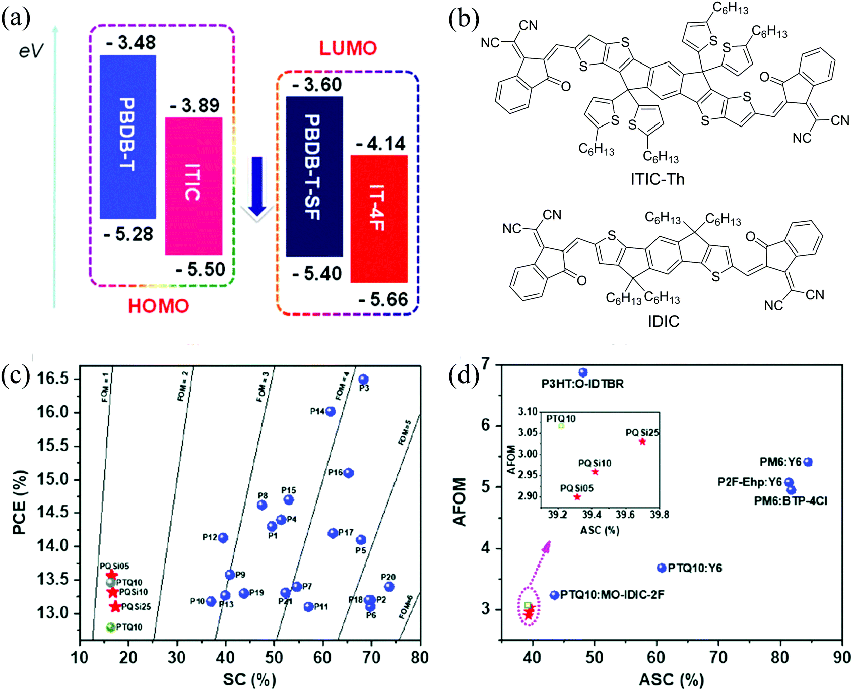 | ||
| Fig. 8 (a) Molecular energy levels of PBDB-T, ITIC, PBDB-T-SF and IT-4F, reproduced from ref. 22 with permission from the American Chemical Society, copyright 2017; (b) chemical structures of ITIC-Th and IDIC; (c) the maximum PCE versus SC of some polymers; and (d) the AFOM versus ASC for the active layers showing high PCEs in single-junction OSCs. Reproduced from ref. 168 with permission from John Wiley and Sons, copyright 2017. | ||
Although fluorination is an effective way to tune the FMO energy levels and molecular packing, the tedious synthesis and low yield would limit further industrial application. Zhang et al.201 replaced the F atoms in PD2 with Cl atoms to form PD3 (PM7). The lower material cost, much shorter synthetic route, and simpler purification of the intermediates made the synthetic cost of PD3 potentially much lower than that for PD2. In addition, introduction of Cl atoms resulted in higher dipole moments and a more delocalized HOMO of the polymer. Except for a slightly lowered EHOMO, the absorption profile, aggregation effect in solution, and film morphology of PD3 were similar to those of PD2. However, a very high PCE of 14.4% was obtained for the PD3:IT-4F blend. Furthermore, the same group introduced Cl atoms at different positions on the thiophene spacers of PD1 to form PD5 and PD6.131 These differences had dramatic effects on the molecular packing and thus the photovoltaic performance. PD6 showed a large redshift of 140 nm in its absorption spectrum with a narrower bandgap of 1.78 eV than PD5 (Eg = 2.11 eV). On the other hand, PD5 showed much weaker aggregation behaviour, poorer crystallinity, and almost no SCLC mobility due to the larger steric effects. Consequently, an extremely low PCE of 0.18% was obtained for PD5:IT-4F, while a much higher PCE of 12.33% was obtained for PD6:IT-4F.
Ye et al.134 developed a similar polymer donor, PD8 (PBT1-C-2Cl), using p-alkylphenyl groups as the side chains of BDT units and introducing Cl atoms on the 4-position of the thiophene spacer. Compared with PD6, PD8 exhibited a lower-lying EHOMO of −5.59 eV and a slightly wider bandgap of 1.85 eV. The devices based on PD8:IT-4F showed much enhanced μh and μe (Table 4), and therefore a higher FF of 76% than that of PD6:IT-4F (70.5%). Thus, a slightly higher PCE of 12.7% was obtained for PD8:IT-4F.
Li et al.135 used fluorinated alkoxyphenyl groups as side chains of BDT to form PD10 (PFOPB). Compared with PD9 (POPB) without fluorination, PD10 possessed a deeper EHOMO, higher extinction coefficient, and higher μh. Higher crystallinity with a smaller phase separation size was obtained for the PD10:IT-4F blend. As a result, a higher PCE of 11.7% was obtained. They also replaced the BDD unit with a naphtho[2,3-c]thiophene-4,9-dione (NTDO) unit as the latter possesses a planar structure and offers several loci in the phenyl ring for functionalization.202 Alkylthio side chains were also introduced to lower EHOMO. The resultant PD11 (PBN-S) showed a low-lying EHOMO of −5.48 eV, high crystallinity, and ordered molecular packing. Benefitting from the efficient charge separation, high and balanced μh and μe, ordered molecular packing, appropriate aggregations, and complementary absorption in the active layer, the devices based on PD11:IT-4F demonstrated a high PCE of 13.10%. The devices showed good storage stability, retaining 88% of their initial PCE after 100 days storage in a nitrogen-filled glove-box.136 A PCE of up to 10.21% with an active area of 100 mm2 was obtained, demonstrating the area scalability of these OSCs.
Benzo[1,2-d:4,5-d′]bis(thiazole) (BBT) is a weak electron-withdrawing building block for structural modification to improve μh and the stability of polymer donors. Wen et al.158 employed BDT and BBT both with alkylthiophene side chains as the D and A units, respectively, and introduced different halogen atoms (F and Cl) on the thiophene side chains of the BDT units to form polymers PO4 (PBB-H), PO5 (PBB-F), and PO6 (PBB-Cl). When blended with IT-4F, similarly high JSC values were obtained for these three polymers due to their high extinction coefficient and favourable face-on orientation. Fluorination and chlorination lowered the energy levels, improved the charge transport, and suppressed recombination, which led to a higher VOC and FF. Among them, the devices based on PO6:IT-4F showed the highest PCE of 14.8%.
Jeon et al.205 synthesized a simple, potentially low cost polymer donor P(Cl) by using BDT and 3-chlorothiophene as D and A units, respectively. P(Cl) showed a high PCE of 12.14% when blended with ITIC-Th (Fig. 8b). Although fluorination or chlorination on BDT units can improve the device performance, the molecular weight and solubility would decrease with the introduction of F or Cl atoms. To achieve a balance between molecular weight and solubility, they introduced a small amount of BDD as A units to form two ternary polymers, PO7 (P(F–Cl)(BDD = 0.2)) and PO8 (P(Cl–Cl)(BDD = 0.2)).159 Both polymers had higher molecular weights and showed better solubility than those without BDD units (P(F–Cl) and P(Cl–Cl)). High PCE values of 12.7% and 13.97% were obtained for PO7:IT-4F and PO8:IT-4F-based OSCs, respectively, when processed from eco-friendly solvents. For the BDT-based polymers, the π-orbitals of BDT show a high degree of localization, which is not beneficial for intramolecular charge carrier delocalization, resulting in low mobilities.49 Replacing the BDT units with imide-oligothiophene can greatly improve the carrier mobility.206 Yu et al.166 developed two polymer donors with D–A1–D–A2 structures using thiophenes as D units and difluorobenzothiadiazole (ffBT) and phthalimide (PhI) or difluoro phthalimide (ffPhI) as the two A units to form PX3 (PhI-ffBT) and PX4 (ffPhI-ffBT), respectively. These polymers are highly crystalline and show a high field effect μh of 0.6–0.9 cm2 V−1 s−1. PX4 has predominantly edge-on polymer backbone orientation, which is not beneficial for the charge transport in the vertical direction in an OSC. Therefore, the PX4:IT-4F blend showed a lower SCLC μh than that of PX3:IT-4F. The PX3:IT-4F blend exhibited tighter π–π stacking and less recombination and higher exciton dissociation and charge collection efficiencies. A higher PCE of 13.31% was obtained for PX3:IT-4F compared to PX4:IT-4F (12.74%).
Sun et al.167 synthesized PX5 (PTQ10) using thiophene and difluorinated quinoxaline as D and A units, respectively, in only two reaction steps with a high overall yield of 87.4%. PX5 possessed a low EHOMO of −5.54 eV and a wide bandgap of 1.92 eV and showed a high PCE of 12.70% when an ITIC derivative, IDIC (Fig. 8b), was used as an acceptor. Yuan et al.168 adopted a combinatory side chain strategy to keep the low synthetic cost while achieving high efficiencies. Siloxane terminated alkoxy and alkoxy groups with different ratios were incorporated to modify PX5 to obtain PX6 (PQSi05), PX7 (PQSi10), and PX8 (PQSi25). Compared with PX5, these polymers showed similar bandgaps, but increased EHOMO with an increasing amount of siloxane-containing side chains, which resulted in a decrease in VOC of OSCs based on their blends with IT-4F. Among them, the PX6:IT-4F blend showed the highest and most balanced μh and μe, least recombination and highest exciton dissociation and charge collection efficiencies (Table 4). Consequently, the devices based on the PX6:IT-4F blend showed the highest PCE of 13.56%. In addition, all these polymers have a low SC and high figure-of-merit (FOM) (a parameter that is related to the manufacturability of OSCs using this material) as well as a low average SC (ASC) and average FOM (AFOM) when considering the cost of acceptors (Fig. 8c and d).168
3.3 High performance polymer donors matching with Y6
In 2019, Yuan et al.9 developed a novel NFA, Y6, which incorporates a BT-based fused-unit as the central core and 2FIC as the end groups (Fig. 6). Compared with ITIC and IT-4F, Y6 has a narrower bandgap of 1.33 eV with a red-shifted optical absorption onset at 931 nm, and a higher αs-max of 2.39 × 10⁵ M−1 cm−1. The bandgap of Y6 is almost ideal for achieving the maximum PCE based on the Shockley–Queisser limit for single junction solar cells (at an Eg of 1.34 eV).43 The ELUMO of −4.1 eV was between those of ITIC and IT-4F. Y6 is the acceptor that has achieved the record PCE of 18.22% so far.10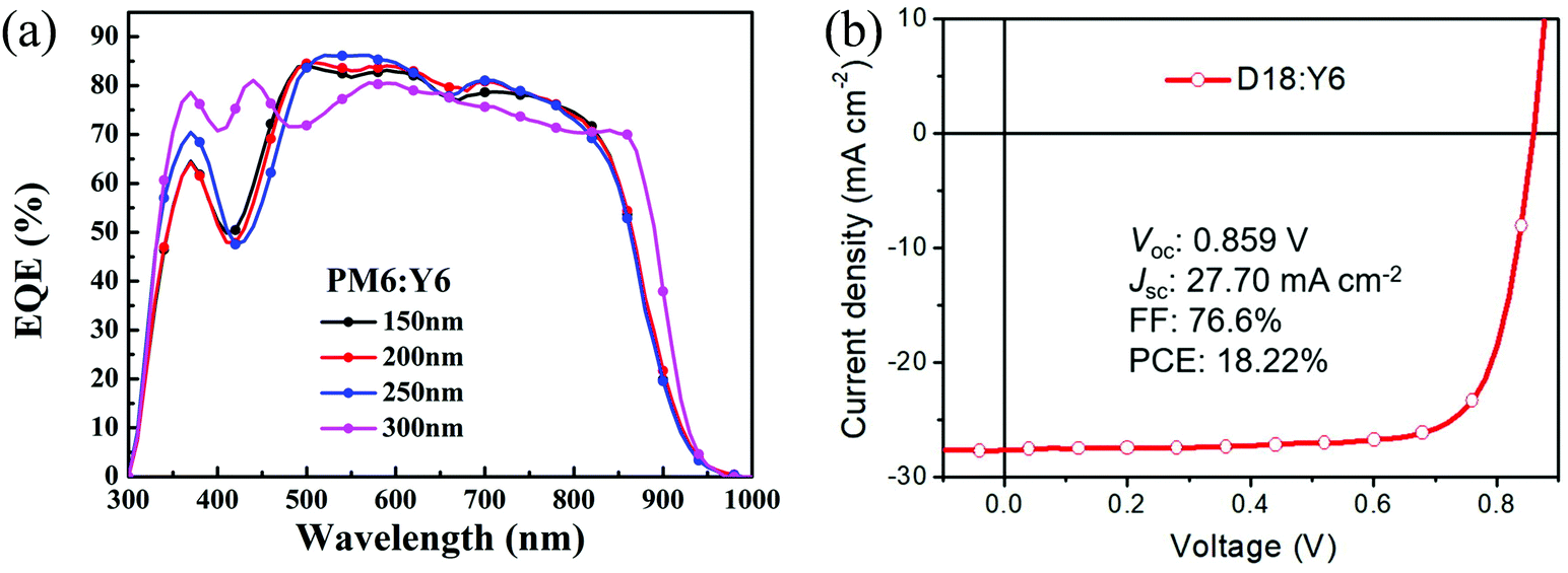 | ||
| Fig. 9 (a) EQE curves of PD2:Y6-based OSCs, reproduced from ref. 9 with permission from Elsevier, copyright 2019; and (b) J–V curve for a PO12:Y6-based OSC, reproduced from ref. 10 with permission from Elsevier, copyright 2020. | ||
As PD8 had shown high performance when blended with IT-4F, Xie et al.207 employed Y6 as an acceptor to blend with PD8. Compared with the IT-4F blend, the Y6 blend showed much wider EQE curves due to the red-shifted absorption of Y6. A much improved JSC of 26.1 mA cm−2 was obtained for PD8:Y6 than that for PD8:IT-4F (19.74 mA cm−2), contributing to the higher PCE of 16.1% of the former.
As mentioned previously, the π-spacer between D and A units plays a key role in improving the coplanarity of the polymer backbone. As a π-spacer, selenophene with lower aromaticity than thiophene can endow a more planar backbone and longer conjugation. Chao et al.138 synthesized three polymers, PD13 (PBB), PD14 (PBBSe-H), and PD15 (PBBSe-Cl), to investigate the influence of selenophene π-spacers as well as chlorination on the performance of OSCs. It was found that PD13 without π-spacers and chlorination showed the most twisted structure with blue-shifted absorption. On the other hand, PD15 with π-spacers and chlorination demonstrated the strongest sunlight harvesting capability with a medium bandgap of 1.73 eV, a deep EHOMO, the largest dipole moment, the most planar polymer backbone, the strongest aggregation, and the highest charge mobility. Therefore, a high PCE of 14.44% was obtained when PD15 was blended with Y6.138
As both F atoms and ester groups can downshift the FMO energy levels and enhance the planarity and hence the charge transport, Sun et al.139 simultaneously introduced these two types of substituents onto the β positions of thiophene to form FE-T as A units and made several terpolymers with BDT and BDD units via random copolymerization. The resultant polymer PD16 (S1) had a low-lying EHOMO of −5.52 eV and enhanced aggregation/crystallinity. Moreover, this ternary strategy enabled a favorable balance between crystallinity and miscibility. When this polymer was blended with Y6, a high PCE of 16.42% was obtained.
Phenazine (Pz) can be considered as a Qx derivative with extended conjugation. Ding et al.154 employed dithieno[3,2-a:2′,3′-c]phenazine (DTPz) and 9,10-difluorodithieno[3,2-a:2′,3′-c]-phenazine (FDTPz) as A units, BDT as D units, and thiophene as π-spacers to form two novel polymer donors, PN27 and PN28, respectively. Both polymers formed complementary absorption with Y6, while the fluorinated polymer PN28 showed a lower EHOMO of −5.46 eV than that of PN27 (−5.33 eV). The devices based on the PN28:Y6 blend showed a higher VOC (0.867 vs. 0.777 V) and a similar JSC compared with PN27:Y6. Moreover, due to the higher and more balanced μh and μe (Table 5), a higher FF (65.8% vs. 61.6%) was obtained for PN28:Y6. Thus, the PN28:Y6 blend showed a higher PCE of 15.14% than that of PN27:Y6 (12.3%).
| Blend | μ h, μe (×10−4 cm2 V−1 s−1), μe(h)/μh(e)a | EQEb (%) | V OC (V) | J SC (mA cm−2) | FF (%) | PCE (%) | S 1 | S 2 | P diss (%) | Ref. |
|---|---|---|---|---|---|---|---|---|---|---|
|
a
μ
e/μh or μh/μe, whichever is >1.
b Maximum value of EQE.
c Obtained from VOC ∼ S1log(Plight).
d Obtained from Jph ∼ S2log(Plight).
e The numbers of significant digits of the data are adopted from the original references and may be different.
|
||||||||||
| PE14:Y6 | 1.18, 0.83, 1.42 | 82 | 0.81 | 26.68 | 74.11 | 16.02 | 1.16 | 0.99 | 123 | |
| PE15:Y6 | 0.87, 1.32, 1.52 | <70 | 0.66 | 19.5 | 46 | 5.9e | 1.27 | 0.98 | 110 | |
| PE16:Y6 | 5.61, 2.42, 2.32 | 83 | 0.83 | 25.6 | 66.7 | 14.2 | 1.59 | 0.9e | 110 | |
| PD2:Y6 | 5.90, 2, 2.95 | 0.83 | 25.3 | 74.8 | 15.7 | 0.975 | 9 | |||
| PD3:Y6 | 7.46, 4.66, 1.60 | 0.897 | 25.644 | 74 | 17.037 | 96.7 | 130 | |||
| PD8:Y6 | 7.1, 5.1, 1.39 | 0.84 | 26.1 | 72.5 | 16.1 | 207 | ||||
| PD13:Y6 | 0.84, 4.1, 5 | 0.84 | 4.25 | 42.36 | 1.51 | 0.9 | 138 | |||
| PD14:Y6 | 3.4, 2.9, 1.17 | 0.65 | 22.23 | 56.4 | 8.17 | 0.95 | 138 | |||
| PD15:Y6 | 7.0, 5.7, 1.22 | 0.82 | 24.07 | 73.16 | 14.44 | 0.96 | 138 | |||
| PD16:Y6 | 7.01, 4.43, 1.67 | 0.877 | 25.402 | 73.7 | 16.421 | 0.978 | 95.8 | 139 | ||
| PN21:Y6 | 8.04, 1.14, 7.05 | 0.84 | 22.21 | 75.43 | 14.02 | 1.27 | 1 | 152 | ||
| PN27:Y6 | 1.33, 0.681, 1.95 | 0.777 | 25.7 | 61.6 | 12.3 | 0.933 | 87.9 | 154 | ||
| PN28:Y6 | 3.42, 2.42, 1.41 | 0.867 | 26.53 | 65.8 | 15.14 | 0.958 | 94.9 | 154 | ||
| PO9:Y6 | 5.62, 4.77, 1.18 | 76 | 0.8 | 23.93 | 74.7 | 14.63 | 0.954 | 96.7 | 161 | |
| PO10:Y6 | 1.60, 2.05, 1.28 | 68 | 0.87 | 20.52 | 70.2 | 12.57 | 0.951 | 94.7 | 161 | |
| PO11:Y6 | 2.82, 2.81, 1.01 | 83 | 0.85 | 25.41 | 74.9 | 16.22 | 0.981 | 97.8 | 160 | |
| PO12:Y6 | 1.49, 1.40, 1.06 | 87 | 0.859 | 27.70 | 76.6 | 18.22 | 10 | |||
| PO13:Y6 | 3.23, 1.51, 2.14 | 85 | 0.88 | 25.87 | 70.7 | 16.16 | 0.959 | 94.6 | 162 | |
| PX5:Y6 | 32.6, 13.5, 2.41 | 0.826 | 26.65 | 75.1 | 16.53 | 0.986 | 99.4 | 208 | ||
| PX9:Y6 | 2.82, 1.25, 2.26 | 0.74 | 22.7 | 65.73 | 11.05 | 169 | ||||
Later, Ding et al.10 used dithieno[3′,2′:3,4;2′′,3′′:5,6]benzo[1,2-c][1,2,5]thiadiazole (DTBT) as the A units and BDT as the D units to synthesize a polymer donor, PO12 (D18), which showed a higher μe of 1.59 × 10⁻⁴ cm2 V−1 s−1 than that of PO11 (1.19 × 10⁻⁴ cm2 V−1 s−1) since DTBT has a larger molecular plane. While the high and balanced μh and μe of the PO12:Y6 blend were responsible for the high FF (76.6%), the complementary absorption contributed to the very high JSC of 27.7 mA cm−2 (Table 5). A PCE of 18.22% was achieved (Fig. 9b), which is the highest value reported for single junction OSCs. They also used fluorine- and alkoxyl-substituted benzene (FAB) as A units to synthesize a new polymer donor PO13 (W1) with a low EHOMO of −5.36 eV and a wide bandgap of 2.16 eV.162 The PO13:Y6 blend achieved a PCE of 16.16%.
PX5 was synthesized with very low cost and showed high performance when blended with IDIC or IT-4F.167,168 When PX5 was blended with Y6, much wider absorption and EQE curves were obtained owing to the red-shifted absorption of Y6.208 In addition, higher μh and μe were also obtained. A largely improved JSC of 26.65 mA cm−2 was achieved, leading to a high PCE of 16.53%.
When J52 was blended with Y6, a low VOC (0.65 V) resulting from the high EHOMO (−5.12 eV) of J52 and a low FF (53.82%) due to the imbalanced μh and μe were obtained, leading to a moderate PCE of 7.15%.169 When IDTT was used to replace BDT in J52, the resulting PX9 (PIDTT-DTffBTA) had a lower EHOMO of −5.25 eV.169 When blended with Y6, more balanced μh and μe were obtained for the blend film. Consequently, a higher VOC of 0.74 V, an improved FF of 65.73%, and an enhanced PCE of 11.05% were obtained.
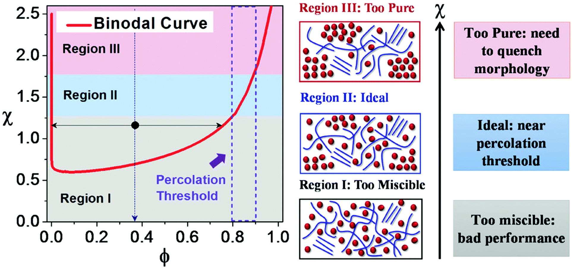 | ||
| Fig. 10 Schematic illustration of three regimes in the Flory–Huggins interaction parameter–polymer volume fraction (χ–ϕ) phase diagram. Regime I, II, and III represent high χ, medium χ (where the purity of the mixed domain is close to the small molecule acceptor percolation threshold), and low χ, respectively. The dashed rectangle marks the reported percolation threshold values where the polymer volume fractions are 0.8–0.9. The composition corresponding to the lower limit for electron transport is termed as the percolation threshold. Reproduced from ref. 228 with permission from John Wiley and Sons, copyright 2018. | ||
3.4 General guidelines for the design of high-performance WBG polymer donors
Based on the above discussions, some useful guidelines for the design of high-performance WBG polymer donors for matching narrow bandgap NFAs are obtained, which are briefly summarized as follows:42,209–212(1) A combination of suitable D and A building blocks to form D–A polymers has been almost exclusively used as the strategy to develop WBG polymer donors for matching narrow bandgap NFAs since desired FMOs and bandgaps can be readily obtained by fine selection of donor and acceptor units with different abilities of electron withdrawing or donating properties.35 Thiophene-containing building blocks have been used in the D units due to their appropriate electron-donating ability to obtain the desired EHOMO and their lower steric effects on the neighbouring units to maintain backbone planarity to achieve high hole mobility. Among them, BDT has been most frequently used due to its large and planar fused-ring extended π-conjugated structure that can facilitate hole transport and more importantly induce face-on crystal orientation for efficient charge transport along the vertical direction in the active layer. Moderately electron-withdrawing building blocks that can maintain a relatively high ELUMO have been utilized as the A units to construct WBG polymer donors. The electron-withdrawing groups among these building blocks are mainly esters, imides, ketones, N-heterocyles (containing sp2 nitrogen), and their combinations. In addition, an electron donating, sterically less demanding π-spacer has often been inserted between the D and A units in a D–A type polymer donor to maintain the backbone planarity and the distance between the D and A units to increase the electronic polarization, which possibly helps stabilize the excitons.213–216
(2) Several strategies can be used to lower EHOMO of the polymer donors: (i) introducing electron-withdrawing groups such as fluorine, chlorine, ester, trifluoromethyl, and alkoxy groups;121,147,148,217,218 (ii) replacing thienyl side chains with alkoxy or alkylthio substituted phenyl side chains;133,219 and (iii) replacing the alkyl side chains with alkylthio groups.220
(3) A coplanar and rigid backbone is needed for high charge carrier mobility, which can be achieved by: (i) extending the conjugation area of the backbone by using larger fused ring building blocks;196 (ii) replacing thiophene with selenophene, which has lower aromaticity and enhanced ground-state quinoid resonance character, resulting in improved planarity and increased effective conjugation length;138 (iii) fluorination or chlorination, which enhances the intermolecular interactions;217,218 and (iv) strengthening intermolecular interactions through side chain engineering221 and introduction of π-spacers.138
3.5 Morphology control in WBG polymer donor:NFA systems
The morphology of the BHJ blend active layer directly impacts the exciton dissociation, charge separation, and transport processes. A bicontinuous network of the donor and acceptor with domain sizes between 10 and 20 nm could provide a large interfacial area between the two domains to facilitate exciton dissociation, while forming a continuous and relatively pure percolating pathway to transport free charges to the corresponding electrodes.222–228 The extent of this phase separation is critical since domains that are too large (greater than the typical exciton diffusion length on the order of tens of nanometres) will favour geminate recombination, whereas too-mixed domains can increase the rate of non-geminate recombination.4,229–231 A favourable morphology can be achieved by tuning the donor:acceptor miscibility and crystallinity.229Herein, we discuss how changing the donor properties, choosing a certain acceptor in the BHJ blend, and modifying the processing conditions would impact the morphology of the donor:acceptor blend and hence the performance of the OSC device.
 | ||
| Fig. 11 Chemical structures of additional NFAs. | ||
A computational approach to studying the charge separation efficiency between polymer donors and NFAs was proposed by Yao et al..121 They found that the larger electrostatic potential difference between a WBG polymer donor (PE12) and NFA (IT-4F) was responsible for a high PCE of 14.7%, even though the driving force for charge separation (energy level offsets) in the blend was quite small.121
The morphology of the donor:acceptor blend can be controlled by pre- and post-deposition treatments of the as-cast film. These morphology optimization methods aim to achieve high average domain purity and highly ordered packing of both the donor and acceptor to minimize charge recombination in NFA-based OSCs.223
Processing solvent additives are well known for regulating the BHJ active layer morphology. Wang et al.239 studied the effect of different concentrations of a common solvent additive DIO (1,8-diiodooctane) in the PD1:ITIC system, using a vertical stratification study of the donor and acceptor. They found an optimal DIO content of 0.5%. It is noteworthy that while an increase in the DIO content (to 1%) leads to abruptly enhanced face-on packing of PD1 (beneficial in OSCs), excessive vertical component distribution and over crystallization of ITIC occur, which results in reduced vertical carrier transport paths for both PD1 and ITIC and a reduced PCE. The device with no additive demonstrated an average PCE of 8.74%, JSC of 15.88 mA cm−2, VOC of 0.892 V, and FF of 61.7%. With 0.5% DIO an increased JSC and FF of 17.23 mA cm−2 and 69.3%, respectively, resulted in a high PCE of 10.75%. With 1% DIO, both JSC and the FF dropped to 15.23 mA cm−2 and 66.8%, respectively, thereby leading to a lower PCE of 9.27%.
Solvent vapor annealing (SVA) is an efficient post-processing technique to control the morphology of the active layer. It serves as a method for molecular level rearrangement by penetrating solvent vapor into the active layer.240,241 Jiao et al.240 used four common annealing solvents, methylene chloride (CH2Cl2), chloroform (CHCl3), tetrahydrofuran (THF), and carbon disulfide (CS2), to study the effect of active layer SVA treatment on the performance of PD3:IT-4Cl-based OPVs, achieving significantly improved performance compared with that of the as-cast OPVs. SVA (especially with CS2) enhanced the charge generation, transport, and collection efficiency. The PD3:IT-4Cl device with CS2 solvent treatment showed the highest PCE of 13.76% with a JSC of 20.53 mA cm−2, a VOC of 0.87 V and a FF of 77.05%, while the control device showed a lower JSC (19.28 mA cm−2) and FF (70.36%), and a similar VOC of 0.88 V with a PCE of 11.94%.
Thermal annealing is another widely used simple method for morphology optimization, mostly due to the temperature-dependent aggregation behaviour of donor–acceptor phases.223,233,242–244 For example, Bin et al.141 reported a more than 25% improvement in the PCE of the PN2:ITIC device upon annealing at 150 °C for 10 min due to enhanced crystalline domains with prominent face-on orientation leading to higher SCLC mobility (improved charge transport) as compared to unannealed devices. The as-prepared PN2:ITIC device showed a PCE of 9.03% with a JSC of 14.81 mA cm−2, a VOC of 0.96 V and a FF of 63.63%, while, upon annealing, the device showed a significantly higher JSC (17.32 mA cm−2) and FF (69.77%) and a similar VOC (0.94 V), resulting in a PCE of 11.41%. Especially for the high performance WBG polymer PD1, with temperature dependent aggregation behavior, thermal annealing is necessary to achieve the optimal photovoltaic performance.141 The critical parameters that determine the effectiveness of thermal annealing for a polymer:NFA system are the glass transition temperature (Tg) and miscibility of the components (χ).233
4 Desirable properties of WBG polymer donors for high efficiency NFA-based OSCs
4.1 Molecular packing and charge transport
The choice of polymer donor will affect not only μh of the blend but also the molecular ordering of the NFAs significantly and thus μe and the domain purity (miscibility).245 A coplanar polymer with reduced steric hindrance in the backbone is favorable for ordered molecular packing and intermolecular charge transport and is correlated with higher μh of neat and blend films. For example, Li et al.119 employed covalent and noncovalent (F⋯S conformational lock) backbone rigidification strategies, respectively, to design two BDT and ester-modified oligothiophene-based copolymers (PE7 and PE8). Hydrogen-bonding interactions induced in the DFDT-based unit in polymer PE8 resulted in stronger interchain π–π interactions, a smaller π–π distance with a longer coherence length (Lc) and thus a significantly higher μh compared to its TT counterpart. A VOC of 0.86 V, a high JSC of 21.83 mA cm−2 and a remarkable FF of 75%, and thus a high PCE of 14.16% were obtained for the PE8:IT-4F device, whereas the PE7:IT-4F device showed a significantly lower JSC (19.34 mA cm−2) and FF (65%), and thus a low PCE of 11.10%. Liu et al.127 designed two new WBG polymers (PE19 (PB2T) and PE20 (PB3T)) based on BDT and oligothiophene units. PE20 exhibits a more planar geometry, whereas PE19 has a highly twisted backbone conformation; therefore, a PCE of 11.9% was achieved for the PE20:IT-M (Fig. 11) device compared to the very poor performance (0.01%) of the PE19:IT-M device. Tang et al.170 used a backbone fluorination strategy to improve the crystallinity (lamellar and π–π packing coherence length) and thus SCLC mobilities, making use of the introduced F⋯F, C–F⋯H, and F⋯S interactions in PX11 (PDTF-TZNT) compared to non-fluorinated counterpart PX11. Consequently, the PX10:IT-M device showed a relatively low PCE of 4.42% with a JSC of 10.15 mA cm−2, a VOC of 0.75 V, and a FF of 58.1%, whereas the PX11:IT-M device obtained a higher PCE of 10.05% with an improved JSC of 17.33 mA cm−2, a VOC of 0.80 V, and a significantly high FF of 72.5%.Achieving high FF requires efficient charge extraction capability facilitated by high mobilities of both holes and electrons. As seen in Fig. 12a, for high performance systems, blend carrier mobilities in excess of 10−4 cm2 V−1 s−1 can achieve a FF of >70%. To achieve such moderate to high mobilities in the device, the polymer donor is preferred to have a planar backbone with moderate aggregation capability, predominantly face-on orientation, and covalent and noncovalent backbone rigidification induced by strategies such as fluorination, conformation locking, and/or side chain modification. In addition, the mobility ratio, crystal sizes, and coherence length of the π–π stacking order of the polymer in the blend are also crucial (OSC performance dependencies on the mobility ratio and (010) coherence length are plotted in Fig. 12b and c, respectively). For perspective, most high-performance systems utilize polymers with neat film SCLC mobilities in excess of 10−4 cm2 V−1 s−1 for achieving a high FF of >60% (Fig. 12d). Importantly, an overly crystalline polymer donor can also lead to decreased miscibility with the NFA in the blend, leading to large pure aggregated domains, which is detrimental to charge transport.236
 | ||
| Fig. 12 Plots of (a) SCLC electron and hole mobilities measured in blend films vs. FF, (b) SCLC mobility ratio (μh/μe) vs. the corresponding FF, (c) coherence length along the [010] direction of crystal packing in blend films vs. the respective PCE, and (d) neat film SCLC mobility vs. the corresponding FF in OSCs with WBG polymer donors and NFAs discussed in this review. | ||
4.2 Matching energy levels for minimizing Eloss
For a long time, it has been considered that a sufficient energy level offset of ≥0.3 eV between organic donor and acceptor materials, ΔEHOMO or ΔELUMO, is required for efficient charge separation mostly based on observations for fullerene-based OSCs.87,121,192–195 This is due to the nature of organic semiconductors, which typically have much larger exciton binding energies (∼0.3–1 eV) than inorganic semiconductors. However, due to the advent of efficient NFAs, several studies have demonstrated highly efficient OSCs with efficient and fast charge separation at a ΔEHOMO (and/or ΔELUMO) much smaller than 0.3 eV. For example, Sun et al.171 used finely tuned WBG polymer donor:NFA acceptor system PX12 (PTQ11):TPT10 (Fig. 11) to achieve highly efficient exciton dissociation and charge transfer, resulting in a high PCE of 16.32% with a high VOC of 0.88 V, a large JSC of 24.79 mA cm−2, and a high FF of 74.8%, despite the zero ΔEHOMO value. Similar instances of a high JSC (high EQE) despite an incredibly low or zero ΔEHOMO or ΔELUMO have been reported elsewhere.65,246–250The voltage loss (Vloss), calculated from the difference between the optical bandgap of the solar cell active layer and VOC of the device (Vloss = Eg/q − VOC), is the key concern for obtaining the maximum performance from a given pair of a WBG polymer donor and NFA.248,250 This voltage loss (also referred to as energy loss, Eloss = eVloss) can be minimized by increasing the difference between ELUMO of the acceptor and EHOMO of the donor as VOC of OSCs is proportional to this difference. Therefore, if fast and efficient charge separation can be achieved in blends with almost no energy offsets, the LUMO and HOMO of the donor polymer could align with the acceptor to minimize ΔEHOMO and ΔELUMO, effectively decreasing Vloss.171 This was one of the two design criteria proposed by Qian et al.,248 where they used spectroscopic and quantum-chemistry approaches to identify key rules for minimizing voltage losses: (1) a low energy offset between the donor and acceptor molecular states and (2) high luminescence of the low-bandgap component.
Nevertheless, several studies have reported the need to fine tune the molecular energy alignment to provide a “certain minimum” driving force for balancing the exciton dissociation probability and VOC loss. Yang et al.65 used structurally similar donor and acceptor combinations (with similar blend morphologies and charge transport properties) to study the performance variations corresponding to their different energy-level offsets. They found that the energy offset has no impact on the charge transport process, but it does affect the exciton dissociation process in NFA-based OSCs. A larger ΔEHOMO between the donor and acceptor can provide sufficient driving force, which contributes to a higher exciton dissociation probability (Pdiss) and PCE. Although minimizing ΔEHOMO can effectively reduce Eloss (or improve VOC), the decreasing driving force will diminish the exciton dissociation process. Moreover, as ΔEHOMO falls below a threshold, Pdiss drops sharply, reducing the overall performance of the device.65 In yet another study investigating the relationship between Eloss and the device performance of NFA-based OSCs, Ling et al.249 found that donor and acceptor blends with an Eloss below 0.6 eV demonstrated inefficient charge transfer between the polymer donor and NFA, resulting in a low EQE and PCE (an example of the trade-off between device performance and energy loss). The PD1:IE-4Cl (Fig. 11)-based device afforded a PCE of 11.1% (with a high JSC of 21.49 mA cm−2 and a moderate FF of 60%) and Eloss of 0.64 eV, whereas the PD1:IEIC based device obtained a low PCE of 3.8% (with a low JSC of 7.65 mA cm−2 and low FF of 45%) despite the lower Eloss of 0.52 eV.
The reasons as to why some polymer donor:acceptor blend systems require a very low ΔEHOMO or ΔELUMO for efficient charge separation and show a very low Eloss are still not well understood, but seem to correlate with both the donor and acceptor materials. More examples are needed to probe the relationships of the structures (chemical and morphological) and optoelectronic properties of the polymer donors with Eloss of the OSC devices, which are extremely important for maximizing the potential of OSCs.
4.3 Characteristics of top performing polymer donors and OSCs
The OSC performance parameters, VOC, JSC, FF, and PCE, of the WBG polymer donors paired with ITIC, IT-4F, and Y6 discussed in this review are plotted in Fig. 13. It can be seen that VOC decreases and JSC increases from ITIC to IT-4F to Y6, while the FF is similar among the three NFAs even though the IT-4F based devices show a slightly higher FF. From ITIC to IT-4F to Y6, the FMO energy levels downshift and the absorption spectra red-shift, which leads to a narrowed optical bandgap, resulting in reduced VOC, but increased JSC. The overall PCE of the OSCs follows the order of ITIC < IT-4F < Y6, which is due to the relatively large contribution of JSC that supersedes the reduction in VOC. The PCE values of the top five high-performing polymer donors and the photovoltaic parameters of the best polymer donor for each NFA are shown in Fig. 14. | ||
| Fig. 13 V OC (a), JSC (b), FF (c), and PCE (d) of high-performance OSCs using WBG polymer donors and different NFAs, ITIC, IT-4F and Y6, discussed in this review. | ||
 | ||
| Fig. 14 Device performances of the top performing polymer donors matching with ITIC, IT-4F and Y6, where the photovoltaic parameters shown are from the best performing PN16:ITIC, PE9:IT-4F and PO12:Y6 systems. | ||
Some distinct characteristics of these high-performance polymer donors (in Fig. 14) can be observed. Firstly, the EHOMO values of the donors matching with ITIC are −5.3 to −5.5 eV, while those of the donors matching with IT-4F and Y6 are −5.5 to −5.6 eV, which are decided by EHOMO of the NFAs since a sufficient ΔEHOMO for efficient dissociation of excitons generated in the NFA phase is required. Secondly, these WBG polymer donors have Eg values of 1.9–2.1 eV that cover the short wavelength region (where the NFAs absorb poorly) to form complementary absorption to achieve high JSC. Lastly, these polymers have SCLC hole mobilities higher than 10−4 cm2 V−1 s−1, which could achieve high and balanced μh and μe in their blends with NFAs, leading to high FF. All these blends have a μh/μe ratio very close to 1 except for PX5:Y6, which has a μh/μe ratio (2.41) greater than 2, where both μh and μe are higher than 10−3 cm2 V−1 s−1, which would probably not impede charge transport even though μh and μe are not well balanced in this case.
5 Conclusions and outlook
In the past few years, tremendous progress has been made in the development of WBG polymer donors that match the emerging high-performance narrow bandgap NFAs, achieving remarkable PCEs of up to 18.22%, which has beaten the predicted PCE limit of ∼10% for OSCs based on fullerene acceptors.251 In this review, we have examined the most representative WBG polymer donors that have been used to match three typical NFAs: ITIC, IT-4F, and Y6. The structure–property–cell performance relationships are probed by analysing the structural design strategies to control and finely tune the FMO energy levels, adjust the light absorption profile, and enhance the hole mobility to match those of different NFAs. The morphology control of the polymer blends to create desirable phase separation and crystallinity for achieving high device performance is also discussed.Despite these recent advances in the development of polymer donors and OSCs in general, there is room for further improvement of the cell performance, while some challenges and issues need to be overcome in order to make OSCs a commercial reality.
(1) Further boosting the PCE of OSCs
(2) Long-term stability
Despite the considerable efforts made over the past few decades, OSCs have not become a commercial reality yet. The stability of OSCs is one of the main obstacles in the path towards commercialization. Solar cells work under various operational stresses such as solar illumination, increased temperature, and exposure to air.102,257–262 The intrinsic degradation mechanisms of the active layer in OSCs include degradation in the dark caused by the morphological changes (rearrangement of donor and acceptor domains) that occur over time and photo-chemical reactions of the organic semiconductor materials in the presence of illumination.263–267 In terms of morphological stability, all-polymer solar cells have attracted much attention since a polymer donor and a polymer acceptor can be entangled to form a much more metastable blend, leading to superior thermal and mechanical stabilities compared to small molecule-based OSCs.268–274 Notable progress has been made in improving the lifetime of OSCs with extrapolated lifetimes (with 80% PCE retention) of over 20 years being demonstrated recently.263,275(3) Fabrication of large area devices
Another big obstacle towards the commercialization of OSCs is the poor scalability of OSC devices. Most, if not all, of the OSCs showing high PCEs greater than 10% are reported with an active area of less than 1 cm2. Increasing the device active area usually results in a significant reduction in the PCE. Although promising large area modules have been reported,276,277 the lab-to-manufacturing translation seems still very challenging and requires urgent attention.278(4) Low cost
Commercialization of OSCs will require a competitive low manufacturing cost-to-PCE ratio along with energy payback and embodied energy metrics comparable to existing silicon solar cells.279,280 It has been predicted that for OSCs having unique merits such as flexibility, lightness, and high throughput manufacturability, a module efficiency of 10% with an operational lifetime of 10 years and a production cost of <$0.5 per Wp would be enough to reach the threshold of commecialization.281 For the donor:acceptor combination to be fully scalable, it should possess a high value of the industrial figure of merit (i-FOM).282–284 This parameter takes account of the synthetic complexity (SC) of the donor and acceptor materials as well as the PCE and lifetime of the OSC device. Most of the high PCE polymer donors require tedious synthesis and use of toxic substances, resulting in very high SC and thus insufficient i-FOM. The importance of developing polymer donors with low SC has been increasingly realized. On the other hand, small molecule donor materials have found increased interest in the last couple of years for their industrial scalability owing to the advantages of well-defined chemical structures, synthetic ease, high purity of materials, and outstanding repeatability from batch to batch synthesis.285,286(5) Environmentally friendly manufacturing
Most of the high performance OSCs are fabricated using halogenated solvents such as o-dichlorobenzene, chlorobenzene, or chloroform, which are environmental hazards. These solvents might be suitable for proof-of-concept lab-based research, but for large scale production alternative eco-friendly solvents (green solvents) need to be used.287,288 As discussed, some polymer donors that can be processed using green solvents and yet show high PCE have been reported.120,289,290Conflicts of interest
There are no conflicts to declare.Acknowledgements
The authors are thankful for the support from the Discovery Grants (RGPIN-2016-04366) and Strategic Partnership Grants for Projects (STPGP 506317-17; STPGP 521458) of the Natural Sciences and Engineering Research Council of Canada (NSERC).Notes and references
- G. Li, R. Zhu and Y. Yang, Nat. Photonics, 2012, 6, 153–161 CrossRef CAS.
- O. Inganäs, Adv. Mater., 2018, 30, 1800388 CrossRef.
- N. Matsuhisa, X. Chen, Z. Bao and T. Someya, Chem. Soc. Rev., 2019, 48, 2946–2966 RSC.
- C. Cui and Y. Li, Energy Environ. Sci., 2019, 12, 3225–3246 RSC.
- G. Yu, J. Gao, J. C. Hummelen, F. Wudl and A. J. Heeger, Science, 1995, 270, 1789–1791 CrossRef CAS.
- Y. Tong, Z. Xiao, X. Du, C. Zuo, Y. Li, M. Lv, Y. Yuan, C. Yi, F. Hao, Y. Hua, T. Lei, Q. Lin, K. Sun, D. Zhao, C. Duan, X. Shao, W. Li, H.-L. Yip, Z. Xiao, B. Zhang, Q. Bian, Y. Cheng, S. Liu, M. Cheng, Z. Jin, S. Yang and L. Ding, Sci. China: Chem., 2020, 63, 758–765 CrossRef CAS.
- Y. Liang, Z. Xu, J. Xia, S.-T. Tsai, Y. Wu, G. Li, C. Ray and L. Yu, Adv. Mater., 2010, 22, E135–E138 CrossRef CAS.
- Y. Lin, J. Wang, Z.-G. Zhang, H. Bai, Y. Li, D. Zhu and X. Zhan, Adv. Mater., 2015, 27, 1170–1174 CrossRef CAS.
- J. Yuan, Y. Zhang, L. Zhou, G. Zhang, H.-L. Yip, T.-K. Lau, X. Lu, C. Zhu, H. Peng, P. A. Johnson, M. Leclerc, Y. Cao, J. Ulanski, Y. Li and Y. Zou, Joule, 2019, 3, 1140–1151 CrossRef CAS.
- Q. Liu, Y. Jiang, K. Jin, J. Qin, J. Xu, W. Li, J. Xiong, J. Liu, Z. Xiao, K. Sun, S. Yang, X. Zhang and L. Ding, Sci. Bull., 2020, 65, 272–275 CrossRef CAS.
- J. C. Hummelen, B. W. Knight, F. LePeq, F. Wudl, J. Yao and C. L. Wilkins, J. Org. Chem., 1995, 60, 532–538 CrossRef CAS.
- J. Peet, J. Y. Kim, N. E. Coates, W. L. Ma, D. Moses, A. J. Heeger and G. C. Bazan, Nat. Mater., 2007, 6, 497–500 CrossRef CAS.
- Y. He, H.-Y. Chen, J. Hou and Y. Li, J. Am. Chem. Soc., 2010, 132, 1377–1382 CrossRef CAS.
- Z. He, C. Zhong, S. Su, M. Xu, H. Wu and Y. Cao, Nat. Photonics, 2012, 6, 591–595 CrossRef.
- J. Zhao, Y. Li, G. Yang, K. Jiang, H. Lin, H. Ade, W. Ma and H. Yan, Nat. Energy, 2016, 1, 15027 CrossRef CAS.
- W. Zhao, D. Qian, S. Zhang, S. Li, O. Inganäs, F. Gao and J. Hou, Adv. Mater., 2016, 28, 4734–4739 CrossRef CAS.
- J. Hou, O. Inganäs, R. H. Friend and F. Gao, Nat. Mater., 2018, 17, 119–128 CrossRef CAS.
- L. Gao, Z.-G. Zhang, H. Bin, L. Xue, Y. Yang, C. Wang, F. Liu, T. P. Russell and Y. Li, Adv. Mater., 2016, 28, 8288–8295 CrossRef CAS.
- H. Bin, Z.-G. Zhang, L. Gao, S. Chen, L. Zhong, L. Xue, C. Yang and Y. Li, J. Am. Chem. Soc., 2016, 138, 4657–4664 CrossRef CAS.
- X. Li, G. Huang, N. Zheng, Y. Li, X. Kang, S. Qiao, H. Jiang, W. Chen and R. Yang, Sol. RRL, 2019, 3, 1900005 CrossRef.
- S. Li, L. Ye, W. Zhao, S. Zhang, S. Mukherjee, H. Ade and J. Hou, Adv. Mater., 2016, 28, 9423–9429 CrossRef CAS.
- W. Zhao, S. Li, H. Yao, S. Zhang, Y. Zhang, B. Yang and J. Hou, J. Am. Chem. Soc., 2017, 139, 7148–7151 CrossRef CAS.
- Y. Yang, Z.-G. Zhang, H. Bin, S. Chen, L. Gao, L. Xue, C. Yang and Y. Li, J. Am. Chem. Soc., 2016, 138, 15011–15018 CrossRef CAS.
- J. Wang, W. Wang, X. Wang, Y. Wu, Q. Zhang, C. Yan, W. Ma, W. You and X. Zhan, Adv. Mater., 2017, 29, 1702125 CrossRef.
- Y. Lin, F. Zhao, Q. He, L. Huo, Y. Wu, T. C. Parker, W. Ma, Y. Sun, C. Wang, D. Zhu, A. J. Heeger, S. R. Marder and X. Zhan, J. Am. Chem. Soc., 2016, 138, 4955–4961 CrossRef CAS.
- F. Zhao, S. Dai, Y. Wu, Q. Zhang, J. Wang, L. Jiang, Q. Ling, Z. Wei, W. Ma, W. You, C. Wang and X. Zhan, Adv. Mater., 2017, 29, 1700144 CrossRef.
- Y. Lin, Q. He, F. Zhao, L. Huo, J. Mai, X. Lu, C.-J. Su, T. Li, J. Wang, J. Zhu, Y. Sun, C. Wang and X. Zhan, J. Am. Chem. Soc., 2016, 138, 2973–2976 CrossRef CAS.
- B. Jia, J. Wang, Y. Wu, M. Zhang, Y. Jiang, Z. Tang, T. P. Russell and X. Zhan, J. Am. Chem. Soc., 2019, 141, 19023–19031 CrossRef CAS.
- S. Dai, F. Zhao, Q. Zhang, T.-K. Lau, T. Li, K. Liu, Q. Ling, C. Wang, X. Lu, W. You and X. Zhan, J. Am. Chem. Soc., 2017, 139, 1336–1343 CrossRef CAS.
- J. Wang, J. Zhang, Y. Xiao, T. Xiao, R. Zhu, C. Yan, Y. Fu, G. Lu, X. Lu, S. R. Marder and X. Zhan, J. Am. Chem. Soc., 2018, 140, 9140–9147 CrossRef CAS.
- T. Li, S. Dai, Z. Ke, L. Yang, J. Wang, C. Yan, W. Ma and X. Zhan, Adv. Mater., 2018, 30, 1705969 CrossRef.
- Y. Ma, Z. Kang and Q. Zheng, J. Mater. Chem. A, 2017, 5, 1860–1872 RSC.
- H. Hu, P. C. Y. Chow, G. Zhang, T. Ma, J. Liu, G. Yang and H. Yan, Acc. Chem. Res., 2017, 50, 2519–2528 CrossRef CAS.
- D. Gedefaw, M. Prosa, M. Bolognesi, M. Seri and M. R. Andersson, Adv. Energy Mater., 2017, 7, 1700575 CrossRef.
- L. Sun, X. Xu, S. Song, Y. Zhang, C. Miao, X. Liu, G. Xing and S. Zhang, Macromol. Rapid Commun., 2019, 40, 1900074 CrossRef.
- A. Wadsworth, M. Moser, A. Marks, M. S. Little, N. Gasparini, C. J. Brabec, D. Baran and I. McCulloch, Chem. Soc. Rev., 2019, 48, 1596–1625 RSC.
- S. Dey, Small, 2019, 15, 1900134 CrossRef.
- G. Zhang, J. Zhao, P. C. Y. Chow, K. Jiang, J. Zhang, Z. Zhu, J. Zhang, F. Huang and H. Yan, Chem. Rev., 2018, 118, 3447–3507 CrossRef CAS.
- S. Suman and S. P. Singh, J. Mater. Chem. A, 2019, 7, 22701–22729 RSC.
- H. Wang, J. Cao, J. Yu, Z. Zhang, R. Geng, L. Yang and W. Tang, J. Mater. Chem. A, 2019, 7, 4313–4333 RSC.
- C. Yan, S. Barlow, Z. Wang, H. Yan, A. K.-Y. Jen, S. R. Marder and X. Zhan, Nat. Rev. Mater., 2018, 3, 18003 CrossRef CAS.
- G. Wang, F. S. Melkonyan, A. Facchetti and T. J. Marks, Angew. Chem., Int. Ed., 2019, 58, 4129–4142 CrossRef CAS.
- W. Shockley and H. J. Queisser, J. Appl. Phys., 1961, 32, 510–519 CrossRef CAS.
- L. Meng, Y. Zhang, X. Wan, C. Li, X. Zhang, Y. Wang, X. Ke, Z. Xiao, L. Ding, R. Xia, H.-L. Yip, Y. Cao and Y. Chen, Science, 2018, 361, 1094–1098 CrossRef CAS.
- T. Ameri, N. Li and C. J. Brabec, Energy Environ. Sci., 2013, 6, 2390 RSC.
- G. Li, W.-H. Chang and Y. Yang, Nat. Rev. Mater., 2017, 2, 17043 CrossRef CAS.
- P. Cheng, G. Li, X. Zhan and Y. Yang, Nat. Photonics, 2018, 12, 131–142 CrossRef CAS.
- K. Ramki, N. Venkatesh, G. Sathiyan, R. Thangamuthu and P. Sakthivel, Org. Electron., 2019, 73, 182–204 CrossRef CAS.
- H. Yao, L. Ye, H. Zhang, S. Li, S. Zhang and J. Hou, Chem. Rev., 2016, 116, 7397–7457 CrossRef CAS.
- U. Mehmood, A. Al-Ahmed and I. A. Hussein, Renewable Sustainable Energy Rev., 2016, 57, 550–561 CrossRef CAS.
- M.-H. Jao, H.-C. Liao and W.-F. Su, J. Mater. Chem. A, 2016, 4, 5784–5801 RSC.
- S. Liu, J. Yuan, W. Deng, M. Luo, Y. Xie, Q. Liang, Y. Zou, Z. He, H. Wu and Y. Cao, Nat. Photonics, 2020, 14, 300–305 CrossRef CAS.
- R. S. Gurney, W. Li, Y. Yan, D. Liu, A. J. Pearson and T. Wang, J. Energy Chem., 2019, 37, 148–156 CrossRef.
- K. Vandewal, J. Benduhn and V. C. Nikolis, Sustainable Energy Fuels, 2018, 2, 538–544 RSC.
- Y. Wang, D. Qian, Y. Cui, H. Zhang, J. Hou, K. Vandewal, T. Kirchartz and F. Gao, Adv. Energy Mater., 2018, 8, 1801352 CrossRef.
- J. Sworakowski, J. Lipiński and K. Janus, Org. Electron., 2016, 33, 300–310 CrossRef CAS.
- B. Dandrade, S. Datta, S. Forrest, P. Djurovich, E. Polikarpov and M. Thompson, Org. Electron., 2005, 6, 11–20 CrossRef CAS.
- R. E. M. Willems, C. H. L. Weijtens, X. de Vries, R. Coehoorn and R. A. J. Janssen, Adv. Energy Mater., 2019, 9, 1803677 CrossRef.
- J. Rivnay, S. C. B. Mannsfeld, C. E. Miller, A. Salleo and M. F. Toney, Chem. Rev., 2012, 112, 5488–5519 CrossRef CAS.
- F. Liu, Y. Gu, X. Shen, S. Ferdous, H.-W. Wang and T. P. Russell, Prog. Polym. Sci., 2013, 38, 1990–2052 CrossRef CAS.
- J. Liu, Y. Sun, X. Gao, R. Xing, L. Zheng, S. Wu, Y. Geng and Y. Han, Langmuir, 2011, 27, 4212–4219 CrossRef CAS.
- J. Liu, M. Arif, J. Zou, S. I. Khondaker and L. Zhai, Macromolecules, 2009, 42, 9390–9393 CrossRef CAS.
- J. H. Litofsky, Y. Lee, M. P. Aplan, B. Kuei, A. Hexemer, C. Wang, Q. Wang and E. D. Gomez, Macromolecules, 2019, 52, 2803–2813 CrossRef CAS.
- Y. Gu, C. Wang and T. P. Russell, Adv. Energy Mater., 2012, 2, 683–690 CrossRef CAS.
- C. Yang, J. Zhang, N. Liang, H. Yao, Z. Wei, C. He, X. Yuan and J. Hou, J. Mater. Chem. A, 2019, 7, 18889–18897 RSC.
- V. D. Mihailetchi, L. J. A. Koster, J. C. Hummelen and P. W. M. Blom, Phys. Rev. Lett., 2004, 93, 216601 CrossRef CAS.
- M. E. Ziffer, S. B. Jo, H. Zhong, L. Ye, H. Liu, F. Lin, J. Zhang, X. Li, H. W. Ade, A. K.-Y. Jen and D. S. Ginger, J. Am. Chem. Soc., 2018, 140, 9996–10008 CrossRef CAS.
- D. Baran, N. Gasparini, A. Wadsworth, C. H. Tan, N. Wehbe, X. Song, Z. Hamid, W. Zhang, M. Neophytou, T. Kirchartz, C. J. Brabec, J. R. Durrant and I. McCulloch, Nat. Commun., 2018, 9, 2059 CrossRef.
- S. R. Cowan, A. Roy and A. J. Heeger, Phys. Rev. B: Condens. Matter Mater. Phys., 2010, 82, 245207 CrossRef.
- L. J. A. Koster, V. D. Mihailetchi, R. Ramaker and P. W. M. Blom, Appl. Phys. Lett., 2005, 86, 123509 CrossRef.
- K. Jiang, G. Zhang, G. Yang, J. Zhang, Z. Li, T. Ma, H. Hu, W. Ma, H. Ade and H. Yan, Adv. Energy Mater., 2018, 8, 1701370 CrossRef.
- R. Sun, Q. Wu, J. Guo, T. Wang, Y. Wu, B. Qiu, Z. Luo, W. Yang, Z. Hu, J. Guo, M. Shi, C. Yang, F. Huang, Y. Li and J. Min, Joule, 2020, 4, 407–419 CrossRef CAS.
- L. Arunagiri, Z. Peng, X. Zou, H. Yu, G. Zhang, Z. Wang, J. Y. Lin Lai, J. Zhang, Y. Zheng, C. Cui, F. Huang, Y. Zou, K. S. Wong, P. C. Y. Chow, H. Ade and H. Yan, Joule, 2020, 4, 1790–1805 CrossRef CAS.
- L. J. A. Koster, V. D. Mihailetchi, H. Xie and P. W. M. Blom, Appl. Phys. Lett., 2005, 87, 203502 CrossRef.
- P. Mark and W. Helfrich, J. Appl. Phys., 1962, 33, 205–215 CrossRef CAS.
- D. Natali and M. Sampietro, J. Appl. Phys., 2002, 92, 5310–5318 CrossRef CAS.
- J. A. Röhr, X. Shi, S. A. Haque, T. Kirchartz and J. Nelson, Phys. Rev. Appl., 2018, 9, 044017 CrossRef.
- R. Mauer, M. Kastler and F. Laquai, Adv. Funct. Mater., 2010, 20, 2085–2092 CrossRef CAS.
- W. E. Spear, J. Non-Cryst. Solids, 1969, 1, 197–214 CrossRef CAS.
- G. Juška, K. Arlauskas, M. Viliūnas and J. Kočka, Phys. Rev. Lett., 2000, 84, 4946–4949 CrossRef.
- G. Juška, K. Arlauskas, M. Viliūnas, K. Genevičius, R. Österbacka and H. Stubb, Phys. Rev. B: Condens. Matter Mater. Phys., 2000, 62, R16235–R16238 CrossRef.
- A. Kokil, K. Yang and J. Kumar, J. Polym. Sci., Part B: Polym. Phys., 2012, 50, 1130–1144 CrossRef CAS.
- A. J. Mozer, C.-Q. Ma, W. W. H. Wong, D. J. Jones, P. Bäuerle and G. G. Wallace, Org. Electron., 2010, 11, 573–582 CrossRef CAS.
- K. Genevičius, R. Österbacka, G. Juška, K. Arlauskas and H. Stubb, Synth. Met., 2003, 137, 1407–1408 CrossRef.
- T. Okachi, T. Nagase, T. Kobayashi and H. Naito, Thin Solid Films, 2008, 517, 1331–1334 CrossRef CAS.
- H. C. F. Martens, H. B. Brom and P. W. M. Blom, Phys. Rev. B: Condens. Matter Mater. Phys., 1999, 60, R8489–R8492 CrossRef CAS.
- T. M. Clarke and J. R. Durrant, Chem. Rev., 2010, 110, 6736–6767 CrossRef CAS.
- M. Engel, F. Kunze, D. C. Lupascu, N. Benson and R. Schmechel, Phys. Status Solidi RRL, 2012, 6, 68–70 CrossRef CAS.
- B. P. Rand, D. P. Burk and S. R. Forrest, Phys. Rev. B: Condens. Matter Mater. Phys., 2007, 75, 115327 CrossRef.
- L. Zhu, Y. Yi and Z. Wei, J. Phys. Chem. C, 2018, 122, 22309–22316 CrossRef CAS.
- S. Chen, S.-W. Tsang, T.-H. Lai, J. R. Reynolds and F. So, Adv. Mater., 2014, 26, 6125–6131 CrossRef CAS.
- S. Y. Leblebici, T. L. Chen, P. Olalde-Velasco, W. Yang and B. Ma, ACS Appl. Mater. Interfaces, 2013, 5, 10105–10110 CrossRef CAS.
- B. Bernardo, D. Cheyns, B. Verreet, R. D. Schaller, B. P. Rand and N. C. Giebink, Nat. Commun., 2014, 5, 1–7 Search PubMed.
- J. A. Carr and S. Chaudhary, Appl. Phys. Lett., 2012, 100, 213902 CrossRef.
- S. Leblebici, J. Lee, A. Weber-Bargioni and B. Ma, J. Phys. Chem. C, 2017, 121, 3279–3285 CrossRef CAS.
- J. Brebels, J. V. Manca, L. Lutsen, D. Vanderzande and W. Maes, J. Mater. Chem. A, 2017, 5, 24037–24050 RSC.
- H.-W. Li, Z. Guan, Y. Cheng, T. Lui, Q. Yang, C.-S. Lee, S. Chen and S.-W. Tsang, Adv. Electron. Mater., 2016, 2, 1600200 CrossRef.
- N. Cho, C. W. Schlenker, K. M. Knesting, P. Koelsch, H.-L. Yip, D. S. Ginger and A. K.-Y. Jen, Adv. Energy Mater., 2014, 4, 1301857 CrossRef.
- P. Schilinsky, C. Waldauf and C. J. Brabec, Appl. Phys. Lett., 2002, 81, 3885–3887 CrossRef CAS.
- G. Li, V. Shrotriya, J. Huang, Y. Yao, T. Moriarty, K. Emery and Y. Yang, Nat. Mater., 2005, 4, 864–868 CrossRef CAS.
- S. Holliday, R. S. Ashraf, A. Wadsworth, D. Baran, S. A. Yousaf, C. B. Nielsen, C.-H. Tan, S. D. Dimitrov, Z. Shang, N. Gasparini, M. Alamoudi, F. Laquai, C. J. Brabec, A. Salleo, J. R. Durrant and I. McCulloch, Nat. Commun., 2016, 7, 11585 CrossRef CAS.
- D. Baran, R. S. Ashraf, D. A. Hanifi, M. Abdelsamie, N. Gasparini, J. A. Röhr, S. Holliday, A. Wadsworth, S. Lockett, M. Neophytou, C. J. M. Emmott, J. Nelson, C. J. Brabec, A. Amassian, A. Salleo, T. Kirchartz, J. R. Durrant and I. McCulloch, Nat. Mater., 2017, 16, 363–369 CrossRef CAS.
- X. Jia, Z. Chen, C. Duan, Z. Wang, Q. Yin, F. Huang and Y. Cao, J. Mater. Chem. C, 2019, 7, 314–323 RSC.
- X. Xu, G. Zhang, L. Yu, R. Li and Q. Peng, Adv. Mater., 2019, 31, 1906045 CrossRef CAS.
- C. Yang, S. Zhang, J. Ren, M. Gao, P. Bi, L. Ye and J. Hou, Energy Environ. Sci., 2020, 13, 2864–2869 RSC.
- B. Zheng, L. Huo and Y. Li, NPG Asia Mater., 2020, 12, 3 CrossRef CAS.
- W. Li, K. H. Hendriks, M. M. Wienk and R. A. J. Janssen, Acc. Chem. Res., 2016, 49, 78–85 CrossRef CAS.
- Y.-W. Su, Y.-C. Lin and K.-H. Wei, J. Mater. Chem. A, 2017, 5, 24051–24075 RSC.
- S.-H. Liao, H.-J. Jhuo, Y.-S. Cheng and S.-A. Chen, Adv. Mater., 2013, 25, 4766–4771 CrossRef CAS.
- J. Zhao, Q. Li, S. Liu, Z. Cao, X. Jiao, Y.-P. Cai and F. Huang, ACS Energy Lett., 2020, 5, 367–375 CrossRef CAS.
- D. Qian, L. Ye, M. Zhang, Y. Liang, L. Li, Y. Huang, X. Guo, S. Zhang, Z. Tan and J. Hou, Macromolecules, 2012, 45, 9611–9617 CrossRef CAS.
- S. C. Price, A. C. Stuart, L. Yang, H. Zhou and W. You, J. Am. Chem. Soc., 2011, 133, 4625–4631 CrossRef CAS.
- Z. Zheng, O. M. Awartani, B. Gautam, D. Liu, Y. Qin, W. Li, A. Bataller, K. Gundogdu, H. Ade and J. Hou, Adv. Mater., 2017, 29, 1604241 CrossRef.
- Y. Wang and T. Michinobu, J. Mater. Chem. C, 2016, 4, 6200–6214 RSC.
- C. Chang, W. Li, X. Guo, B. Guo, C. Ye, W. Su, Q. Fan and M. Zhang, Org. Electron., 2018, 58, 82–87 CrossRef CAS.
- D. H. Kim, T. T. Trang Bui, S. Rasool, C. E. Song, H. K. Lee, S. K. Lee, J.-C. Lee, W.-W. So and W. S. Shin, ACS Appl. Mater. Interfaces, 2019, 11, 2189–2196 CrossRef CAS.
- Y. An, X. Liao, L. Chen, J. Yin, Q. Ai, Q. Xie, B. Huang, F. Liu, A. K.-Y. Jen and Y. Chen, Adv. Funct. Mater., 2018, 28, 1706517 CrossRef.
- S. Li, L. Ye, W. Zhao, H. Yan, B. Yang, D. Liu, W. Li, H. Ade and J. Hou, J. Am. Chem. Soc., 2018, 140, 7159–7167 CrossRef CAS.
- S. Li, W. Zhao, J. Zhang, X. Liu, Z. Zheng, C. He, B. Xu, Z. Wei and J. Hou, Chem. Mater., 2020, 32, 1993–2003 CrossRef CAS.
- Y. Cui, H. Yao, L. Hong, T. Zhang, Y. Xu, K. Xian, B. Gao, J. Qin, J. Zhang, Z. Wei and J. Hou, Adv. Mater., 2019, 31, 1808356 CrossRef.
- H. Yao, Y. Cui, D. Qian, C. S. Ponseca, A. Honarfar, Y. Xu, J. Xin, Z. Chen, L. Hong, B. Gao, R. Yu, Y. Zu, W. Ma, P. Chabera, T. Pullerits, A. Yartsev, F. Gao and J. Hou, J. Am. Chem. Soc., 2019, 141, 7743–7750 CrossRef CAS.
- C. Yao, Y. Zhu, K. Gu, J. Zhao, J. Ning, D. F. Perepichka, Y.-L. Loo and H. Meng, J. Mater. Chem. A, 2020, 8, 12149–12155 RSC.
- B. Fan, D. Zhang, M. Li, W. Zhong, Z. Zeng, L. Ying, F. Huang and Y. Cao, Sci. China: Chem., 2019, 62, 746–752 CrossRef CAS.
- U. Huynh, T. Basel, T. Xu, L. Lu, T. Zheng, L. Yu and V. Vardeny, in Physical Chemistry of Interfaces and Nanomaterials Xiii, ed. N. Banerji, S. C. Hayes and C. Silva, Spie-Int Soc Optical Engineering, Bellingham, 2014, vol. 9165, p. UNSP91650Z Search PubMed.
- S. Zhang, M. A. Uddin, W. Zhao, L. Ye, H. Y. Woo, D. Liu, B. Yang, H. Yao, Y. Cui and J. Hou, Polym. Chem., 2015, 6, 2752–2760 RSC.
- L. Ye, S. Zhang, W. Zhao, H. Yao and J. Hou, Chem. Mater., 2014, 26, 3603–3605 CrossRef CAS.
- D. Liu, B. Yang, B. Jang, B. Xu, S. Zhang, C. He, H. Y. Woo and J. Hou, Energy Environ. Sci., 2017, 10, 546–551 RSC.
- Q. Fan, Q. Zhu, Z. Xu, W. Su, J. Chen, J. Wu, X. Guo, W. Ma, M. Zhang and Y. Li, Nano Energy, 2018, 48, 413–420 CrossRef CAS.
- M. Zhang, X. Guo, W. Ma, H. Ade and J. Hou, Adv. Mater., 2015, 27, 4655–4660 CrossRef CAS.
- R. Ma, T. Liu, Z. Luo, Q. Guo, Y. Xiao, Y. Chen, X. Li, S. Luo, X. Lu, M. Zhang, Y. Li and H. Yan, Sci. China: Chem., 2020, 63, 325–330 CrossRef CAS.
- Y. Wu, C. An, L. Shi, L. Yang, Y. Qin, N. Liang, C. He, Z. Wang and J. Hou, Angew. Chem., Int. Ed., 2018, 57, 12911–12915 CrossRef CAS.
- Z. Xu, Q. Fan, X. Meng, X. Guo, W. Su, W. Ma, M. Zhang and Y. Li, Chem. Mater., 2017, 29, 4811–4818 CrossRef CAS.
- Q. Fan, Z. Xu, X. Guo, X. Meng, W. Li, W. Su, X. Ou, W. Ma, M. Zhang and Y. Li, Nano Energy, 2017, 40, 20–26 CrossRef CAS.
- L. Ye, Y. Xie, K. Weng, H. S. Ryu, C. Li, Y. Cai, H. Fu, D. Wei, H. Y. Woo, S. Tan and Y. Sun, Nano Energy, 2019, 58, 220–226 CrossRef CAS.
- W. Li, G. Li, H. Guo, X. Guo, B. Guo, Q. Zhu, Q. Fan, W. Ma, M. Zhang and Y. Li, J. Mater. Chem. A, 2019, 7, 1307–1314 RSC.
- Y. Wu, H. Yang, Y. Zou, Y. Dong, J. Yuan, C. Cui and Y. Li, Energy Environ. Sci., 2019, 12, 675–683 RSC.
- Y. Li, D. Liu, J. Wang, Z.-G. Zhang, Y. Li, Y. Liu, T. Zhu, X. Bao, M. Sun and R. Yang, Chem. Mater., 2017, 29, 8249–8257 CrossRef CAS.
- P. Chao, M. Guo, Y. Zhu, H. Chen, M. Pu, H.-H. Huang, H. Meng, C. Yang and F. He, Macromolecules, 2020, 53, 2893–2901 CrossRef CAS.
- H. Sun, T. Liu, J. Yu, T.-K. Lau, G. Zhang, Y. Zhang, M. Su, Y. Tang, R. Ma, B. Liu, J. Liang, K. Feng, X. Lu, X. Guo, F. Gao and H. Yan, Energy Environ. Sci., 2019, 12, 3328–3337 RSC.
- H. Bin, Y. Yang, Z. Peng, L. Ye, J. Yao, L. Zhong, C. Sun, L. Gao, H. Huang, X. Li, B. Qiu, L. Xue, Z.-G. Zhang, H. Ade and Y. Li, Adv. Energy Mater., 2018, 8, 1702324 CrossRef.
- H. Bin, L. Gao, Z.-G. Zhang, Y. Yang, Y. Zhang, C. Zhang, S. Chen, L. Xue, C. Yang, M. Xiao and Y. Li, Nat. Commun., 2016, 7, 13651 CrossRef CAS.
- H. Bin, L. Zhong, Y. Yang, L. Gao, H. Huang, C. Sun, X. Li, L. Xue, Z.-G. Zhang, Z. Zhang and Y. Li, Adv. Energy Mater., 2017, 7, 1700746 CrossRef.
- L. Xue, Y. Yang, J. Xu, C. Zhang, H. Bin, Z.-G. Zhang, B. Qiu, X. Li, C. Sun, L. Gao, J. Yao, X. Chen, Y. Yang, M. Xiao and Y. Li, Adv. Mater., 2017, 29, 1703344 CrossRef.
- Z. Liao, Y. Xie, L. Chen, Y. Tan, S. Huang, Y. An, H. S. Ryu, X. Meng, X. Liao, B. Huang, Q. Xie, H. Y. Woo, Y. Sun and Y. Chen, Adv. Funct. Mater., 2019, 29, 1808828 CrossRef.
- W. Su, G. Li, Q. Fan, Q. Zhu, X. Guo, J. Chen, J. Wu, W. Ma, M. Zhang and Y. Li, J. Mater. Chem. A, 2019, 7, 2351–2359 RSC.
- Z. Li, X. Xu, G. Zhang, T. Yu, Y. Li and Q. Peng, Sol. RRL, 2018, 2, 1800186 CrossRef.
- W. Li, G. Li, X. Guo, B. Guo, Z. Bi, H. Guo, W. Ma, X. Ou, M. Zhang and Y. Li, J. Mater. Chem. A, 2017, 5, 19680–19686 RSC.
- W. Li, G. Li, X. Guo, Y. Wang, H. Guo, Q. Xu, M. Zhang and Y. Li, J. Mater. Chem. A, 2018, 6, 6551–6558 RSC.
- W. Chen, G. Huang, X. Li, Y. Li, H. Wang, H. Jiang, Z. Zhao, D. Yu, E. Wang and R. Yang, ACS Appl. Mater. Interfaces, 2019, 11, 33173–33178 CrossRef CAS.
- D. Liu, K. Zhang, Y. Zhong, C. Gu, Y. Li and R. Yang, J. Mater. Chem. A, 2018, 6, 18125–18132 RSC.
- L. Lan, Z. Chen, Q. Hu, L. Ying, R. Zhu, F. Liu, T. P. Russell, F. Huang and Y. Cao, Adv. Sci., 2016, 3, 1600032 CrossRef.
- A. Tang, Q. Zhang, M. Du, G. Li, Y. Geng, J. Zhang, Z. Wei, X. Sun and E. Zhou, Macromolecules, 2019, 52, 6227–6233 CrossRef CAS.
- S. Xu, X. Wang, L. Feng, Z. He, H. Peng, V. Cimrová, J. Yuan, Z.-G. Zhang, Y. Li and Y. Zou, J. Mater. Chem. A, 2018, 6, 3074–3083 RSC.
- W. Li, Q. Liu, K. Jin, M. Cheng, F. Hao, W.-Q. Wu, S. Liu, Z. Xiao, S. Yang, S. Shi and L. Ding, Mater. Chem. Front., 2020, 4, 1454–1458 RSC.
- T. Yu, X. Xu, G. Zhang, J. Wan, Y. Li and Q. Peng, Adv. Funct. Mater., 2017, 27, 1701491 CrossRef.
- X. Xu, T. Yu, Z. Bi, W. Ma, Y. Li and Q. Peng, Adv. Mater., 2018, 30, 1703973 CrossRef.
- G. Xu, L. Chen, H. Lei, Z. Liao, N. Yi, J. Liu and Y. Chen, J. Mater. Chem. A, 2019, 7, 4145–4152 RSC.
- S. Wen, Y. Li, N. Zheng, I. O. Raji, C. Yang and X. Bao, J. Mater. Chem. A, 2020, 8, 13671–13678 RSC.
- S. J. Jeon, Y. W. Han and D. K. Moon, Small, 2019, 15, 1902598 CrossRef CAS.
- J. Xiong, K. Jin, Y. Jiang, J. Qin, T. Wang, J. Liu, Q. Liu, H. Peng, X. Li, A. Sun, X. Meng, L. Zhang, L. Liu, W. Li, Z. Fang, X. Jia, Z. Xiao, Y. Feng, X. Zhang, K. Sun, S. Yang, S. Shi and L. Ding, Sci. Bull., 2019, 64, 1573–1576 CrossRef CAS.
- J. Liu, L. Liu, C. Zuo, Z. Xiao, Y. Zou, Z. Jin and L. Ding, Sci. Bull., 2019, 64, 1655–1657 CrossRef CAS.
- T. Wang, J. Qin, Z. Xiao, X. Meng, C. Zuo, B. Yang, H. Tan, J. Yang, S. Yang, K. Sun, S. Xie and L. Ding, Sci. Bull., 2020, 65, 179–181 CrossRef CAS.
- Y. Qin, M. A. Uddin, Y. Chen, B. Jang, K. Zhao, Z. Zheng, R. Yu, T. J. Shin, H. Y. Woo and J. Hou, Adv. Mater., 2016, 28, 9416–9422 CrossRef CAS.
- Y.-S. Wu, Y.-C. Lin, S.-Y. Hung, C.-K. Chen, Y.-C. Chiang, C.-C. Chueh and W.-C. Chen, Macromolecules, 2020, 53, 4968–4981 CrossRef CAS.
- K. He, X. Li, H. Liu, Z. Zhang, P. Kumar, J. H. L. Ngai, J. Wang and Y. Li, Asian J. Org. Chem., 2020, 9, 1301–1308 CrossRef CAS.
- J. Yu, P. Chen, C. W. Koh, H. Wang, K. Yang, X. Zhou, B. Liu, Q. Liao, J. Chen, H. Sun, H. Y. Woo, S. Zhang and X. Guo, Adv. Sci., 2018, 1801743 Search PubMed.
- C. Sun, F. Pan, H. Bin, J. Zhang, L. Xue, B. Qiu, Z. Wei, Z.-G. Zhang and Y. Li, Nat. Commun., 2018, 9, 743 CrossRef.
- D. Yuan, F. Pan, L. Zhang, H. Jiang, M. Chen, W. Tang, G. Qin, Y. Cao and J. Chen, Sol. RRL, 2020, 2000062 CrossRef CAS.
- F. Li, A. Tang, B. Zhang and E. Zhou, ACS Macro Lett., 2019, 8, 1599–1604 CrossRef CAS.
- D. Tang, J. Wan, X. Xu, Y. W. Lee, H. Y. Woo, K. Feng and Q. Peng, Nano Energy, 2018, 53, 258–269 CrossRef CAS.
- C. Sun, S. Qin, R. Wang, S. Chen, F. Pan, B. Qiu, Z. Shang, L. Meng, C. Zhang, M. Xiao, C. Yang and Y. Li, J. Am. Chem. Soc., 2020, 142, 1465–1474 CrossRef CAS.
- W. Su, Q. Fan, X. Guo, X. Meng, Z. Bi, W. Ma, M. Zhang and Y. Li, Nano Energy, 2017, 38, 510–517 CrossRef CAS.
- H. Hwang, D. H. Sin, C. Park and K. Cho, Sci. Rep., 2019, 9, 12081 CrossRef.
- Q. Li, Y. Sun, X. Xue, S. Yue, K. Liu, M. Azam, C. Yang, Z. Wang, F. Tan and Y. Chen, ACS Appl. Mater. Interfaces, 2019, 11, 3299–3307 CrossRef CAS.
- M.-A. Pan, T.-K. Lau, Y. Tang, Y.-C. Wu, T. Liu, K. Li, M.-C. Chen, X. Lu, W. Ma and C. Zhan, J. Mater. Chem. A, 2019, 7, 20713–20722 RSC.
- J. Wang, J. Xu, N. Yao, D. Zhang, Z. Zheng, S. Xie, X. Zhang, F. Zhang, H. Zhou, C. Zhang and Y. Zhang, J. Phys. Chem. Lett., 2019, 10, 4110–4116 CrossRef CAS.
- Q. Yue, H. Wu, Z. Zhou, M. Zhang, F. Liu and X. Zhu, Adv. Mater., 2019, 31, 1904283 CrossRef CAS.
- B. Fan, K. Zhang, X.-F. Jiang, L. Ying, F. Huang and Y. Cao, Adv. Mater., 2017, 29, 1606396 CrossRef.
- Y. He and Y. Li, Phys. Chem. Chem. Phys., 2011, 13, 1970–1983 RSC.
- C. Zhang, S. Langner, A. V. Mumyatov, D. V. Anokhin, J. Min, J. D. Perea, K. L. Gerasimov, A. Osvet, D. A. Ivanov, P. Troshin, N. Li and C. J. Brabec, J. Mater. Chem. A, 2017, 5, 17570–17579 RSC.
- W. Liu, J. Zhang, Z. Zhou, D. Zhang, Y. Zhang, S. Xu and X. Zhu, Adv. Mater., 2018, 30, 1800403 CrossRef.
- J. Sun, X. Ma, Z. Zhang, J. Yu, J. Zhou, X. Yin, L. Yang, R. Geng, R. Zhu, F. Zhang and W. Tang, Adv. Mater., 2018, 30, 1707150 CrossRef.
- C. Huang, X. Liao, K. Gao, L. Zuo, F. Lin, X. Shi, C.-Z. Li, H. Liu, X. Li, F. Liu, Y. Chen, H. Chen and A. K.-Y. Jen, Chem. Mater., 2018, 30, 5429–5434 CrossRef CAS.
- W. Gao, T. Liu, R. Ming, Z. Luo, K. Wu, L. Zhang, J. Xin, D. Xie, G. Zhang, W. Ma, H. Yan and C. Yang, Adv. Funct. Mater., 2018, 28, 1803128 CrossRef.
- J. Cao, S. Qu, J. Yu, Z. Zhang, R. Geng, L. Yang, H. Wang, F. Du and W. Tang, Mater. Chem. Front., 2020, 4, 924–932 RSC.
- H. Bin, L. Zhong, Z.-G. Zhang, L. Gao, Y. Yang, L. Xue, J. Zhang, Z. Zhang and Y. Li, Sci. China: Chem., 2016, 59, 1317–1322 CrossRef CAS.
- J. Min, Z.-G. Zhang, S. Zhang and Y. Li, Chem. Mater., 2012, 24, 3247–3254 CrossRef CAS.
- Y. Li, L. Zhong, J.-D. Lin, F.-P. Wu, H.-J. Bin, Z. Zhang, L. Xu, Z.-Q. Jiang, Z.-G. Zhang, F. Liu, T. P. Russell, Y. Li, L.-S. Liao and S. R. Forrest, Sol. RRL, 2017, 1, 1700107 CrossRef.
- A. Patra and M. Bendikov, J. Mater. Chem., 2010, 20, 422–433 RSC.
- S. S. Zade, N. Zamoshchik and M. Bendikov, Chem. – Eur. J., 2009, 15, 8613–8624 CrossRef CAS.
- L. Liu, G. Zhang, B. He, S. Liu, C. Duan and F. Huang, Mater. Chem. Front., 2017, 1, 499–506 RSC.
- Y. Xu, H. Yao, L. Ma, J. Wang and J. Hou, Rep. Prog. Phys., 2020, 83, 082601 CrossRef CAS.
- A. C. Jakowetz, M. L. Böhm, A. Sadhanala, S. Huettner, A. Rao and R. H. Friend, Nat. Mater., 2017, 16, 551–557 CrossRef CAS.
- S. Gélinas, A. Rao, A. Kumar, S. L. Smith, A. W. Chin, J. Clark, T. S. van der Poll, G. C. Bazan and R. H. Friend, Science, 2014, 343, 512–516 CrossRef.
- B. A. Gregg, J. Phys. Chem. Lett., 2011, 2, 3013–3015 CrossRef CAS.
- Y. Dong, X. Hu, C. Duan, P. Liu, S. Liu, L. Lan, D. Chen, L. Ying, S. Su, X. Gong, F. Huang and Y. Cao, Adv. Mater., 2013, 25, 3683–3688 CrossRef CAS.
- M. Wang, X. Hu, P. Liu, W. Li, X. Gong, F. Huang and Y. Cao, J. Am. Chem. Soc., 2011, 133, 9638–9641 CrossRef CAS.
- Y. Li, J. Geng, Y. Liu, S. Yu and G. Zhao, ChemMedChem, 2013, 8, 27–41 CrossRef CAS.
- R. Po, G. Bianchi, C. Carbonera and A. Pellegrino, Macromolecules, 2015, 48, 453–461 CrossRef CAS.
- Q. Fan, W. Su, Y. Wang, B. Guo, Y. Jiang, X. Guo, F. Liu, T. P. Russell, M. Zhang and Y. Li, Sci. China: Chem., 2018, 61, 531–537 CrossRef CAS.
- S. Zhang, Y. Qin, J. Zhu and J. Hou, Adv. Mater., 2018, 30, 1800868 CrossRef.
- C. Cui, X. Fan, M. Zhang, J. Zhang, J. Min and Y. Li, Chem. Commun., 2011, 47, 11345 RSC.
- Q. Fan, W. Su, X. Meng, X. Guo, G. Li, W. Ma, M. Zhang and Y. Li, Sol. RRL, 2017, 1, 1700020 CrossRef.
- B. Guo, W. Li, X. Guo, X. Meng, W. Ma, M. Zhang and Y. Li, Adv. Mater., 2017, 29, 1702291 CrossRef.
- S. J. Jeon, Y. W. Han and D. K. Moon, Sol. RRL, 2019, 3, 1900094 CrossRef.
- X. Guo, N. Zhou, S. J. Lou, J. Smith, D. B. Tice, J. W. Hennek, R. P. Ortiz, J. T. L. Navarrete, S. Li, J. Strzalka, L. X. Chen, R. P. H. Chang, A. Facchetti and T. J. Marks, Nat. Photonics, 2013, 7, 825–833 CrossRef CAS.
- Y. Xie, Y. Cai, L. Zhu, R. Xia, L. Ye, X. Feng, H. Yip, F. Liu, G. Lu, S. Tan and Y. Sun, Adv. Funct. Mater., 2020, 2002181 CrossRef CAS.
- Y. Wu, Y. Zheng, H. Yang, C. Sun, Y. Dong, C. Cui, H. Yan and Y. Li, Sci. China: Chem., 2020, 63, 265–271 CrossRef CAS.
- Y. Lin, F. Zhao, Y. Wu, K. Chen, Y. Xia, G. Li, S. K. K. Prasad, J. Zhu, L. Huo, H. Bin, Z.-G. Zhang, X. Guo, M. Zhang, Y. Sun, F. Gao, Z. Wei, W. Ma, C. Wang, J. Hodgkiss, Z. Bo, O. Inganäs, Y. Li and X. Zhan, Adv. Mater., 2017, 29, 1604155 CrossRef.
- Y. Geng, A. Tang, K. Tajima, Q. Zeng and E. Zhou, J. Mater. Chem. A, 2019, 7, 64–96 RSC.
- J. Zhang, L. Zhu and Z. Wei, Small Methods, 2017, 1, 1700258 CrossRef.
- H. Lee, C. Park, D. H. Sin, J. H. Park and K. Cho, Adv. Mater., 2018, 30, 1800453 CrossRef.
- S. Namuangruk, S. Jungsuttiwong, N. Kungwan, V. Promarak, T. Sudyoadsuk, B. Jansang and M. Ehara, Theor. Chem. Acc., 2016, 135, 14 Search PubMed.
- B. F. Minaev, G. V. Baryshnikov and V. A. Minaeva, Dyes Pigm., 2012, 92, 531–536 CrossRef CAS.
- Z. Sun, Y. Jiang, L. Zeng and L. Huang, ChemSusChem, 2019, 12, 1325–1333 CrossRef CAS.
- S. Jungsuttiwong, T. Yakhanthip, Y. Surakhot, J. Khunchalee, T. Sudyoadsuk, V. Promarak, N. Kungwan and S. Namuangruk, J. Comput. Chem., 2012, 33, 1517–1523 CrossRef CAS.
- H. Yao, J. Wang, Y. Xu, S. Zhang and J. Hou, Acc. Chem. Res., 2020, 53, 822–832 CrossRef CAS.
- Q. Zhang, M. A. Kelly, N. Bauer and W. You, Acc. Chem. Res., 2017, 50, 2401–2409 CrossRef CAS.
- J. Yuan, L. Qiu, Z.-G. Zhang, Y. Li, Y. Chen and Y. Zou, Nano Energy, 2016, 30, 312–320 CrossRef CAS.
- Y. Wu, Y. Zou, H. Yang, Y. Li, H. Li, C. Cui and Y. Li, ACS Appl. Mater. Interfaces, 2017, 9, 37078–37086 CrossRef CAS.
- Y. Li, N. Zheng, L. Yu, S. Wen, C. Gao, M. Sun and R. Yang, Adv. Mater., 2019, 31, 1807832 CrossRef.
- X. Jiao, L. Ye and H. Ade, Adv. Energy Mater., 2017, 7, 1700084 CrossRef.
- L. Ye, W. Zhao, S. Li, S. Mukherjee, J. H. Carpenter, O. Awartani, X. Jiao, J. Hou and H. Ade, Adv. Energy Mater., 2017, 7, 1602000 CrossRef.
- J. Song, M. Zhang, M. Yuan, Y. Qian, Y. Sun and F. Liu, Small Methods, 2018, 2, 1700229 CrossRef.
- T. Liu, L. Huo, S. Chandrabose, K. Chen, G. Han, F. Qi, X. Meng, D. Xie, W. Ma, Y. Yi, J. M. Hodgkiss, F. Liu, J. Wang, C. Yang and Y. Sun, Adv. Mater., 2018, 30, 1707353 CrossRef.
- J. Chen, Z. Bi, X. Xu, Q. Zhang, S. Yang, S. Guo, H. Yan, W. You and W. Ma, Adv. Sci., 2019, 6, 1801560 CrossRef.
- L. Yang, Z. Hu, Z. Zhang, J. Cao, H. Wang, J. Yu, F. Zhang and W. Tang, J. Mater. Chem. A, 2020, 8, 5458–5466 RSC.
- L. Ye, B. A. Collins, X. Jiao, J. Zhao, H. Yan and H. Ade, Adv. Energy Mater., 2018, 8, 1703058 CrossRef.
- H. Fu, Z. Wang and Y. Sun, Angew. Chem., Int. Ed., 2019, 58, 4442–4453 CrossRef CAS.
- S. Xiao, Q. Zhang and W. You, Adv. Mater., 2017, 29, 1601391 CrossRef.
- S. Holliday, Y. Li and C. K. Luscombe, Prog. Polym. Sci., 2017, 70, 34–51 CrossRef CAS.
- L. Ye, S. Li, X. Liu, S. Zhang, M. Ghasemi, Y. Xiong, J. Hou and H. Ade, Joule, 2019, 3, 443–458 CrossRef CAS.
- M. Ghasemi, H. Hu, Z. Peng, J. J. Rech, I. Angunawela, J. H. Carpenter, S. J. Stuard, A. Wadsworth, I. McCulloch, W. You and H. Ade, Joule, 2019, 3, 1328–1348 CrossRef CAS.
- L. Ye, H. Hu, M. Ghasemi, T. Wang, B. A. Collins, J.-H. Kim, K. Jiang, J. H. Carpenter, H. Li, Z. Li, T. McAfee, J. Zhao, X. Chen, J. L. Y. Lai, T. Ma, J.-L. Bredas, H. Yan and H. Ade, Nat. Mater., 2018, 17, 253–260 CrossRef CAS.
- N. Yi, Q. Ai, W. Zhou, L. Huang, L. Zhang, Z. Xing, X. Li, J. Zeng and Y. Chen, Chem. Mater., 2019, 31, 10211–10224 CrossRef CAS.
- X. Xue, K. Weng, F. Qi, Y. Zhang, Z. Wang, J. Ali, D. Wei, Y. Sun, F. Liu, M. Wan, J. Liu and L. Huo, Adv. Energy Mater., 2019, 9, 1802686 CrossRef.
- H. Cha, G. Fish, J. Luke, A. Alraddadi, H. H. Lee, W. Zhang, Y. Dong, S. Limbu, A. Wadsworth, I. P. Maria, L. Francàs, H. L. Sou, T. Du, J.-S. Kim, M. A. McLachlan, I. McCulloch and J. R. Durrant, Adv. Energy Mater., 2019, 9, 1901254 CrossRef.
- Z. Zheng, H. Yao, L. Ye, Y. Xu, S. Zhang and J. Hou, Mater. Today, 2020, 35, 115–130 CrossRef CAS.
- L.-M. Wang, Q. Li, S. Liu, Z. Cao, Y.-P. Cai, X. Jiao, H. Lai, W. Xie, X. Zhan and T. Zhu, ACS Appl. Mater. Interfaces, 2020, 12, 24165–24173 CrossRef CAS.
- C. Jiao, C. Pang and Q. An, Int. J. Energy Res., 2019, 43, 8716–8724 CrossRef CAS.
- M. Zhang, F. Zhang, Q. An, Q. Sun, W. Wang, X. Ma, J. Zhang and W. Tang, J. Mater. Chem. A, 2017, 5, 3589–3598 RSC.
- M. B. Upama, N. K. Elumalai, M. A. Mahmud, M. Wright, D. Wang, C. Xu and A. Uddin, Sol. Energy Mater. Sol. Cells, 2018, 176, 109–118 CrossRef CAS.
- W. Li, J. Cai, Y. Yan, F. Cai, S. Li, R. S. Gurney, D. Liu, J. D. McGettrick, T. M. Watson, Z. Li, A. J. Pearson, D. G. Lidzey, J. Hou and T. Wang, Sol. RRL, 2018, 2, 1800114 CrossRef.
- W. Ma, C. Yang, X. Gong, K. Lee and A. J. Heeger, Adv. Funct. Mater., 2005, 15, 1617–1622 CrossRef CAS.
- H. Hu, K. Jiang, P. C. Y. Chow, L. Ye, G. Zhang, Z. Li, J. H. Carpenter, H. Ade and H. Yan, Adv. Energy Mater., 2018, 8, 1701674 CrossRef.
- S. Li, L. Zhan, Y. Jin, G. Zhou, T. Lau, R. Qin, M. Shi, C. Li, H. Zhu, X. Lu, F. Zhang and H. Chen, Adv. Mater., 2020, 2001160 CrossRef CAS.
- J. Yuan, T. Huang, P. Cheng, Y. Zou, H. Zhang, J. L. Yang, S.-Y. Chang, Z. Zhang, W. Huang, R. Wang, D. Meng, F. Gao and Y. Yang, Nat. Commun., 2019, 10, 570 CrossRef CAS.
- D. Qian, Z. Zheng, H. Yao, W. Tress, T. R. Hopper, S. Chen, S. Li, J. Liu, S. Chen, J. Zhang, X.-K. Liu, B. Gao, L. Ouyang, Y. Jin, G. Pozina, I. A. Buyanova, W. M. Chen, O. Inganäs, V. Coropceanu, J.-L. Bredas, H. Yan, J. Hou, F. Zhang, A. A. Bakulin and F. Gao, Nat. Mater., 2018, 17, 703–709 CrossRef CAS.
- L. Hong, H. Yao, R. Yu, Y. Xu, B. Gao, Z. Ge and J. Hou, ACS Appl. Mater. Interfaces, 2019, 11, 29124–29131 CrossRef CAS.
- S. M. Menke, N. A. Ran, G. C. Bazan and R. H. Friend, Joule, 2018, 2, 25–35 CrossRef CAS.
- G. Dennler, M. C. Scharber and C. J. Brabec, Adv. Mater., 2009, 21, 1323–1338 CrossRef CAS.
- M. Jeong, I. W. Choi, E. M. Go, Y. Cho, M. Kim, B. Lee, S. Jeong, Y. Jo, H. W. Choi, J. Lee, J.-H. Bae, S. K. Kwak, D. S. Kim and C. Yang, Science, 2020, 369, 1615 CAS.
- Y. Ji, L. Xu, X. Hao and K. Gao, Sol. RRL, 2020, 4, 2000130 CrossRef.
- Z.-H. Chen, P.-Q. Bi, X.-Y. Yang, M.-S. Niu, K.-N. Zhang, L. Feng and X.-T. Hao, J. Phys. Chem. C, 2019, 123, 12676–12683 CAS.
- J. H. Bombile, M. J. Janik and S. T. Milner, Phys. Chem. Chem. Phys., 2019, 21, 11999–12011 RSC.
- X. Jiang, J. Yang, S. Karuthedath, J. Li, W. Lai, C. Li, C. Xiao, L. Ye, Z. Ma, Z. Tang, F. Laquai and W. Li, Angew. Chem., Int. Ed., 2020, 59, 2–12 CrossRef.
- K. Wang, Y. Li and Y. Li, Macromol. Rapid Commun., 2020, 41, 1900437 CrossRef CAS.
- W. R. Mateker and M. D. McGehee, Adv. Mater., 2017, 29, 1603940 CrossRef.
- P. Cheng and X. Zhan, Chem. Soc. Rev., 2016, 45, 2544–2582 RSC.
- M. Jørgensen, K. Norrman, S. A. Gevorgyan, T. Tromholt, B. Andreasen and F. C. Krebs, Adv. Mater., 2012, 24, 580–612 CrossRef.
- M. Giannouli, V. M. Drakonakis, A. Savva, P. Eleftheriou, G. Florides and S. A. Choulis, ChemPhysChem, 2015, 16, 1134–1154 CrossRef CAS.
- G. A. dos, R. Benatto, B. Roth, M. Corazza, R. R. Søndergaard, S. A. Gevorgyan, M. Jørgensen and F. C. Krebs, Nanoscale, 2016, 8, 318–326 RSC.
- X. Xu, J. Xiao, G. Zhang, L. Wei, X. Jiao, H.-L. Yip and Y. Cao, Sci. Bull., 2020, 65, 208–216 CrossRef CAS.
- J. Xiao, M. Ren, G. Zhang, J. Wang, D. Zhang, L. Liu, N. Li, C. J. Brabec, H.-L. Yip and Y. Cao, Sol. RRL, 2019, 3, 1900077 CrossRef.
- J. Guo, Y. Wu, R. Sun, W. Wang, J. Guo, Q. Wu, X. Tang, C. Sun, Z. Luo, K. Chang, Z. Zhang, J. Yuan, T. Li, W. Tang, E. Zhou, Z. Xiao, L. Ding, Y. Zou, X. Zhan, C. Yang, Z. Li, C. J. Brabec, Y. Li and J. Min, J. Mater. Chem. A, 2019, 7, 25088–25101 RSC.
- X. Du, T. Heumueller, W. Gruber, A. Classen, T. Unruh, N. Li and C. J. Brabec, Joule, 2019, 3, 215–226 CrossRef CAS.
- N. Y. Doumon, M. V. Dryzhov, F. V. Houard, V. M. Le Corre, A. Rahimi Chatri, P. Christodoulis and L. J. A. Koster, ACS Appl. Mater. Interfaces, 2019, 11, 8310–8318 CrossRef CAS.
- Z. Li, W. Zhong, L. Ying, F. Liu, N. Li, F. Huang and Y. Cao, Nano Energy, 2019, 64, 103931 CrossRef CAS.
- Y. Zhang, Y. Xu, M. J. Ford, F. Li, J. Sun, X. Ling, Y. Wang, J. Gu, J. Yuan and W. Ma, Adv. Energy Mater., 2018, 8, 1800029 CrossRef.
- K. Zhang, R. Xia, B. Fan, X. Liu, Z. Wang, S. Dong, H.-L. Yip, L. Ying, F. Huang and Y. Cao, Adv. Mater., 2018, 30, 1803166 CrossRef.
- Y.-Y. Yu, C.-H. Chen, C.-C. Chueh, C.-Y. Chiang, J.-H. Hsieh, C.-P. Chen and W.-C. Chen, ACS Appl. Mater. Interfaces, 2017, 9, 27853–27862 CrossRef CAS.
- T. Kim, R. Younts, W. Lee, S. Lee, K. Gundogdu and B. J. Kim, J. Mater. Chem. A, 2017, 5, 22170–22179 RSC.
- T. Kim, J. Choi, H. J. Kim, W. Lee and B. J. Kim, Macromolecules, 2017, 50, 6861–6871 CrossRef CAS.
- T. Kim, J.-H. Kim, T. E. Kang, C. Lee, H. Kang, M. Shin, C. Wang, B. Ma, U. Jeong, T.-S. Kim and B. J. Kim, Nat. Commun., 2015, 6, 8547 CrossRef CAS.
- Q. Burlingame, X. Huang, X. Liu, C. Jeong, C. Coburn and S. R. Forrest, Nature, 2019, 573, 394–397 CrossRef CAS.
- X. Meng, L. Zhang, Y. Xie, X. Hu, Z. Xing, Z. Huang, C. Liu, L. Tan, W. Zhou, Y. Sun, W. Ma and Y. Chen, Adv. Mater., 2019, 31, 1903649 CrossRef CAS.
- S. H. Park, S. Park, S. Lee, J. Kim, H. Ahn, B. J. Kim, B. Chae and H. J. Son, Nano Energy, 2020, 77, 105147 CrossRef CAS.
- P. Meredith and A. Armin, Nat. Commun., 2018, 9, 1–4 CrossRef.
- J. Guo and J. Min, Adv. Energy Mater., 2019, 9, 1802521 CrossRef.
- A. Gambhir, P. Sandwell and J. Nelson, Sol. Energy Mater. Sol. Cells, 2016, 156, 49–58 CrossRef CAS.
- N. Li and C. J. Brabec, Nat. Energy, 2017, 2, 772–773 CrossRef CAS.
- N. Li, I. McCulloch and C. J. Brabec, Energy Environ. Sci., 2018, 11, 1355–1361 RSC.
- J. Min, Y. N. Luponosov, C. Cui, B. Kan, H. Chen, X. Wan, Y. Chen, S. A. Ponomarenko, Y. Li and C. J. Brabec, Adv. Energy Mater., 2017, 7, 1700465 CrossRef.
- E. Bundgaard, F. Livi, O. Hagemann, J. E. Carlé, M. Helgesen, I. M. Heckler, N. K. Zawacka, D. Angmo, T. T. Larsen-Olsen, G. A. dos R. Benatto, B. Roth, M. V. Madsen, M. R. Andersson, M. Jørgensen, R. R. Søndergaard and F. C. Krebs, Adv. Energy Mater., 2015, 5, 1402186 CrossRef.
- D. Hu, Q. Yang, H. Chen, F. Wobben, V. M. L. Corre, R. Singh, T. Liu, R. Ma, H. Tang, L. J. A. Koster, T. Duan, H. Yan, Z. Kan, Z. Xiao and S. Lu, Energy Environ. Sci., 2020, 13, 2134–2141 RSC.
- R. Ilmi, A. Haque and M. S. Khan, Org. Electron., 2018, 58, 53–62 CrossRef CAS.
- S. Dong, K. Zhang, B. Xie, J. Xiao, H.-L. Yip, H. Yan, F. Huang and Y. Cao, Adv. Energy Mater., 2019, 9, 1802832 CrossRef.
- K. An, W. Zhong and L. Ying, Org. Electron., 2020, 82, 105701 CrossRef CAS.
- S. Strohm, F. Machui, S. Langner, P. Kubis, N. Gasparini, M. Salvador, I. McCulloch, H.-J. Egelhaaf and C. J. Brabec, Energy Environ. Sci., 2018, 11, 2225–2234 RSC.
- Y. Qin, L. Ye, S. Zhang, J. Zhu, B. Yang, H. Ade and J. Hou, J. Mater. Chem. A, 2018, 6, 4324–4330 RSC.
| This journal is © The Royal Society of Chemistry 2021 |