Hierarchical structures lead to high thermoelectric performance in Cum+nPb100SbmTe100Se2m (CLAST)†
Received
1st November 2020
, Accepted 2nd December 2020
First published on 8th December 2020
Abstract
Ternary compound CuSbSe2-alloyed PbTe, CumPb100SbmTe100Se2m (CLAST), presents outstanding n-type thermoelectric transport behavior and features hierarchical Cu-based precipitates and interstitials that can balance phonon and carrier transport. Results show that a small amount of CuSbSe2 (∼3%) alloying in CLAST can realize a room-temperature carrier concentration of ∼1.7 × 1018 cm−3 and then optimize the power factor, and simultaneously precipitate out embedded Cu-based nanostructures in the matrix to lower the lattice thermal conductivity. Additionally, extra Cu atoms adding in CLAST can form interstitials and further improve both the carrier concentration to ∼3.0 × 1018 cm−3 and carrier mobility to ∼1227.8 cm2 V−1 s−1 at room temperature, which benefits a maximum power factor of ∼20.0 μW cm−1 K−2 in Cu3.3Pb100Sb3Te100Se6. Moreover, the Cu interstitials together with massive Cu-based nanoprecipitates can strongly scatter a wide set of phonons, and largely lower the lattice thermal conductivity to ∼0.44 W m−1 K−1 in Cu3.4Pb100Sb3Te100Se6 at 623 K. Finally, these Cu-based hierarchical structures in CLAST samples can synergistically optimize the phonon and carrier transport properties and contribute to a high ZT of ∼0.5 at 300 K and a peak ZT of ∼1.4 at 723 K. A remarkably high ZTave of ∼0.94 at 300–723 K is achieved in Cu3.3Pb100Sb3Te100Se6 due to high ZT values in the low temperature range, outperforming other high-performance n-type PbTe-based thermoelectric materials.
Broader context
With more than 60% of input energy being lost as waste heat, thermoelectric materials which make it possible to directly and reversibly convert heat into electrical energy have received ever-increasing attention. Lead telluride (PbTe), a kind of traditional mid-temperature thermoelectric material, has been well-developed in the past few decades. For PbTe-based materials, due to the favorable complex electronic band structures, abundant studies indicate that p-type materials exhibit better thermoelectric performance than n-type counterparts, therefore the optimization of n-type materials to match p-type counterparts is becoming an urgent issue. Here, we report an n-type PbTe system, Cum+nPb100SbmTe100Se2m (abbreviated as CLAST), achieving a room-temperature superior ZT of ∼0.5 and a high ZT of ∼1.4 at 723 K through designing hierarchical microstructures of nanoprecipitates and atomic interstitials. Alloying CuSbSe2 into PbTe improves the power factor and concurrently reduces the thermal conductivity through producing nanoprecipitations. And then, extra Cu interstitials are added, which enhance carrier concentration, maintain carrier mobility, and further suppress thermal conductivity. This work provides a valuable path to collectively optimize carrier and phonon transport.
|
Introduction
Thermoelectric technology makes it possible to directly convert heat into electricity based on the Seebeck effect, which is a promising energy source.1–5 The thermoelectric conversion efficiency strongly depends on the dimensionless figure of merit ZT of materials, ZT = S2σT/(κlat + κele), where S is the Seebeck coefficient, σ is electrical conductivity, T is absolute temperature in kelvin, κlat is lattice thermal conductivity and κele is electronic thermal conductivity. Achieving high S, high σ, and low κlat and κele is the key to acquiring high-performance thermoelectric materials. Due to the coupled relationships between these thermoelectric parameters, obtaining a high ZT value by synchronously optimizing carrier and phonon transport properties is pretty difficult.6–9 Strategies for scattering phonons with different wavelengths include point defects (including substitutional atoms,10,11 interstitial atoms,12,13 and vacancies14,15), grain boundaries16–18 and nanoscale precipitates embedded in the matrix.19–21 Various kinds of methods aim to enhance the power factor (S2σ), including optimization of the carrier concentration and carrier mobility22–24 and band structure manipulations (resonant states25 and band convergence26–28).
As a traditional mid-temperature range material for thermoelectric power generation, PbTe has been intensively investigated.29–32 Recently, p-type PbTe has attained record-high ZT and ZTave with synergistically optimized strategies of manipulating valence band convergence and nanostructuring, such as PbTe–Na–SrTe,33 PbTe–Na–PbS,34 PbTe–S–K,35etc. Although p-type PbTe has been well developed and presents high thermoelectric performance, the thermoelectric performance in n-type counterparts still maintains at a relatively low level, causing a hindrance to widely practical applications of PbTe-based materials. Due to the large offset (∼0.45 eV) between the conduction bands in n-type PbTe,36,37 the strategies to enhance the thermoelectric performance are very different with the p-type PbTe. Most previous research focuses on improving the electrical transport properties by optimizing the carrier concentration or suppressing thermal conductivity by nanostructure design. For instance, In or Ga elements doped in n-type PbTe to form a defect level can well optimize the carrier concentration and finally obtain high power factor.38–41 Sn alloying in n-type PbTe to sharpen the conduction band shape can well optimize the carrier effective mass, and maintain relatively high carrier mobility and power factor.42,43 However, these studies mainly focus on optimizing carrier transport but still maintain high thermal conductivity, which limits the development of thermoelectric performance. Some researchers are devoted to reducing the lattice thermal conductivity by nanostructures, such as PbTe–ZnTe,44 PbTe–CdTe,45 PbTe–CaTe,46 PbTe–PbSnS2,47etc. However, the existence of nanoprecipitates reinforces the scattering of carriers, in turn damaging the power factor. It can be seen that previous studies could not achieve high power factor and low lattice thermal conductivity at the same time. Therefore, it is essential to develop new approaches to realize high thermoelectric performance by balancing carrier and phonon transport properties.
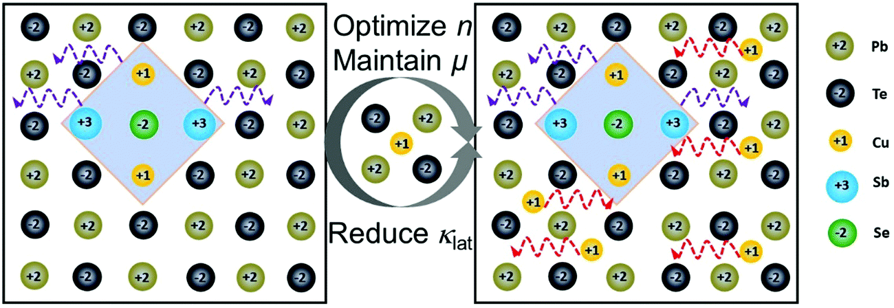
This work reported a high-performance n-type Cum+nPb100SbmTe100Se2m (abbreviated as CLAST in the following text) thermoelectric material with hierarchical structures including Cu-based nanoscale precipitates and atomic interstitials, and the proposed structures are schematically shown in Fig. 1. High-performance CLAST is obtained by firstly alloying ternary compound CuSbSe2 to form nanoprecipitates and then adding extra Cu to form atomic Cu interstitials. Interestingly, these hierarchical structures in the CLAST matrix can not only well strengthen the power factor but also depress the lattice thermal conductivity. With CuSbSe2 alloying and extra Cu added, the room-temperature carrier concentration and carrier mobility can be optimized to ∼3.0 × 1018 cm−3 and ∼1227.8 cm2 V−1 s−1, which contributes to a maximum power factor of ∼20.0 μW cm−1 K−2 in Cu3.3Pb100Sb3Te100Se6. Furthermore, the minimum lattice thermal conductivity can reach as low as ∼0.44 W m−1 K−1 in Cu3.4Pb100Sb3Te100Se6 at 623 K. As a result, a room-temperature ZT of ∼0.5 and a peak ZT of ∼1.4 at 723 K are achieved in Cu3.3Pb100Sb3Te100Se6 through two-step introducing hierarchical structures of nanoprecipitates and interstitials, leading to a transporting balance between carrier and phonon.
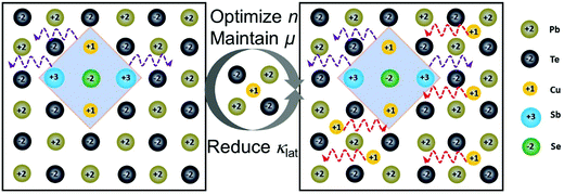 |
| | Fig. 1 Schematic of Cu-based forms in CLAST. Nanoscale Cu-based precipitates form in CLAST with ternary compound CuSbSe2 alloying, and then atomic Cu interstitials appear with extra Cu atoms added. These hierarchical structures can effectively optimize the carrier concentration (n), maintain high carrier mobility (μ) and simultaneously intensively reduce the lattice thermal conductivity (κlat). | |
Results and discussion
To obtain high-performance n-type PbTe-based thermoelectric materials, this work synergistically optimizes the carrier and phonon transport properties by artificially introducing Cu-based hierarchical structures into CumPb100SbmTe100Se2m (CLAST). More experiment details are in the ESI.† Firstly, ternary compound CuSbSe2 alloying in PbTe forms Cu-based nanostructures to dramatically lower the lattice thermal conductivity. Then, extra Cu is utilized and forms interstitial atoms, leading to both a good synergistic optimization of carrier and phonon transport and a further diminution in lattice thermal conductivity. To unveil the origin of high performance in CLAST thermoelectrics, the microstructure observations are conducted to systematically investigate the existing forms of Cu atoms.
Crystal structure identification in CLAST
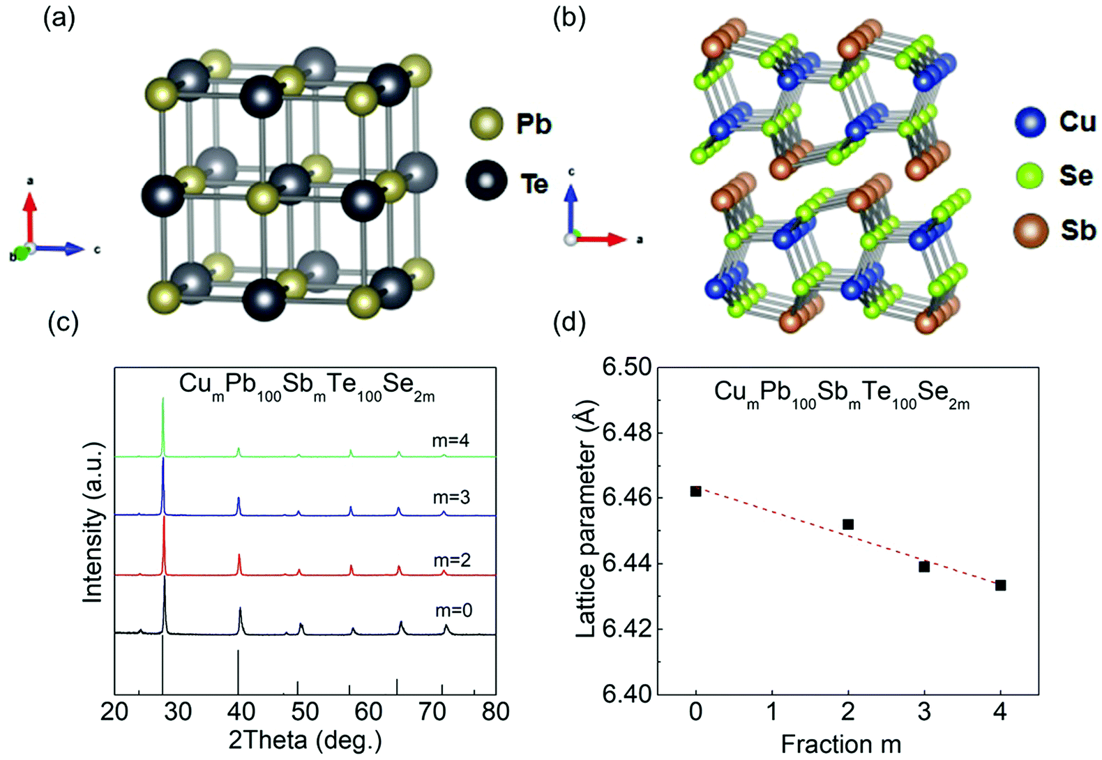
As shown in Fig. 2(a) and (b), PbTe has a cubic rock-salt structure with the Fm3m space group, and CuSbSe2 exhibits a 2D double-layered structure with the Pnma space group. Besides, the lattice parameters between these two phases are very different, CuSbSe2: a ∼ 6.40 Å, b ∼ 3.95 Å, c ∼ 15.3 Å, and PbTe: a = b = c ∼ 6.44 Å. From the XRD patterns, a small amount of CuSbSe2 alloyed with PbTe is dominated by the NaCl structure, named as CumPb100SbmTe100Se2m (CLAST). Meanwhile, no impurity phase can be found in the powder XRD measurement of the CumPb100SbmTe100Se2m (m = 0, 2, 3, 4) samples due to the detection limit of the equipment. Noticeably, the following TEM results disclose that some Cu-based nanostructures indeed precipitate out in the CLAST sample, which will be discussed later. In Fig. 2(d), the falling lattice parameter with the increase of CuSbSe2 content indicates that small-sized Cu+ (∼0.46 Å) and Sb3+ (∼0.92 Å) can partly incorporate in Pb2+ (∼1.2 Å) sites, and small-sized Se2− (∼1.98 Å) incorporates in Te2− (∼2.1 Å) sites.
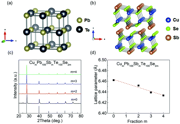 |
| | Fig. 2 Crystal structures of PbTe and CuSbSe2, and phase identification of CumPb100SbmTe100Se2m (CLAST) (m = 0, 2, 3, 4): (a) PbTe crystal structure; (b) CuSbSe2 crystal structure; (c) powder XRD pattern; (d) lattice parameter. | |
Thermal and electrical transport properties in CLAST
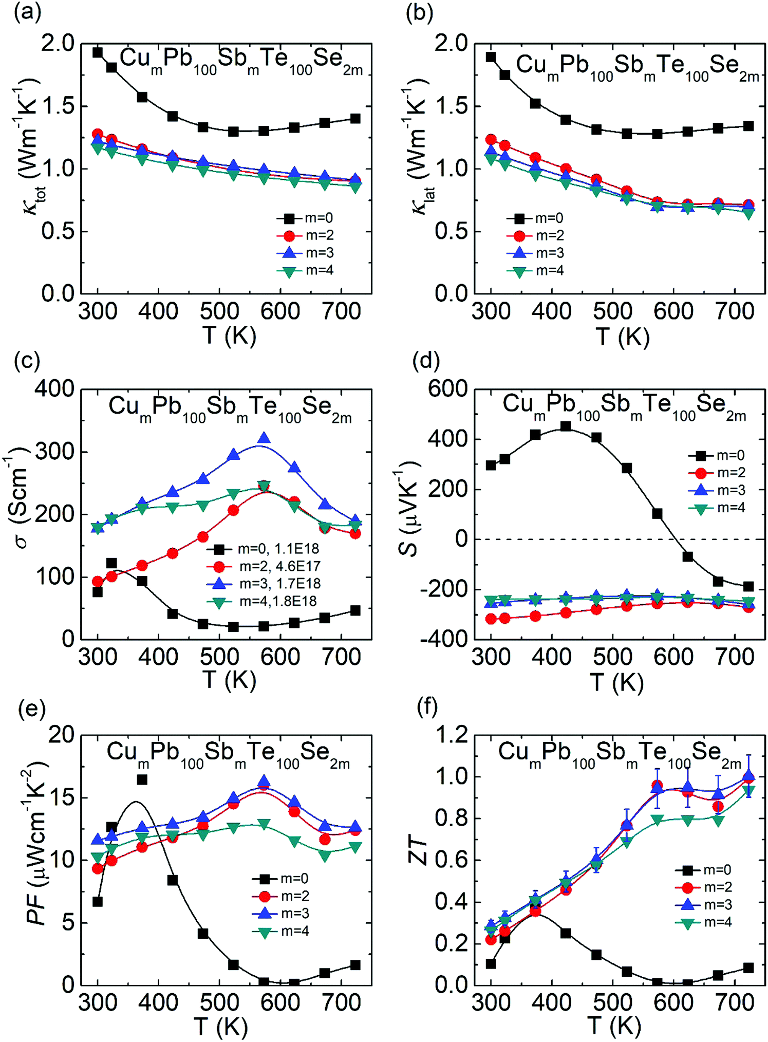
In Fig. 3(a), compared with undoped PbTe, the total thermal conductivity of CLAST is obviously low. The lattice thermal conductivity is equal to the total thermal conductivity minus electronic thermal conductivity, and the electronic thermal conductivity is computed by κele = LσT, where L is the Lorenz number, σ is electrical conductivity and T is the temperature in kelvin. With the incremental CuSbSe2 content, the total thermal conductivity is gradually lowered because of the decreased lattice thermal conductivity with nano-precipitate scattering (detailed discussion is given below), as shown in Fig. 3(b). The minimum lattice thermal conductivity is suppressed from ∼1.28 W m−1 K−1 in PbTe to ∼0.65 W m−1 K−1 in Cu4Pb100Sb4Te100Se8. In Fig. 3(c), the optimal electrical conductivity is promoted to ∼320.7 S cm−1 in Cu3Pb100Sb3Te100Se6 at 573 K because of the improved carrier concentration. Specifically, the temperature-dependent electrical conductivity shows a trend of first rising and then falling in CLAST samples, which may originate from the combination of dynamic doping and phase transition of the Cu-containing phase in CLAST.48,49 In Fig. 3(d), undoped PbTe experiences a p–n transformation, and CLAST exhibits n-type semiconductor characteristic with the negative Seebeck coefficient. The absolute value of room-temperature Seebeck coefficient is reduced from ∼316.7 μV K−1 to ∼239.3 μV K−1. Integrating the improved electrical conductivity and Seebeck coefficient, the maximum power factor reaches ∼16.3 μW cm−1 K−1 in Cu3Pb100Sb3Te100Se6 at 573 K, as shown in Fig. 3(e). Finally, the ZT values reflect an incremental trend with temperature, and a maximum ZT of ∼1.0 is achieved in Cu3Pb100Sb3Te100Se6 at 723 K, as shown in Fig. 3(f). Other thermoelectric data with respect to CLAST are listed in Fig. S1 and S2 (ESI†), such as Lorenz number L, electronic thermal conductivity κele, heat capacity Cp, thermal diffusivity D, and sample density ρ.
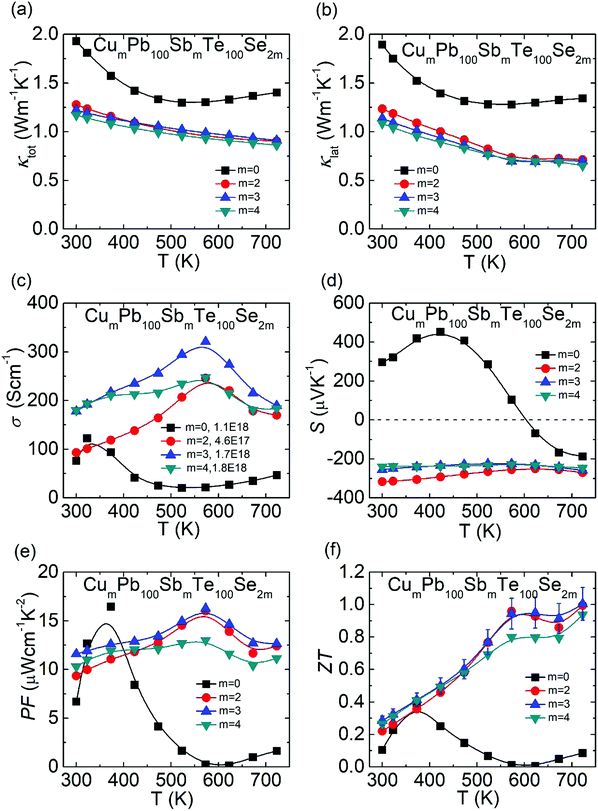 |
| | Fig. 3 Thermoelectric transport properties of CumPb100SbmTe100Se2m (m = 0, 2, 3, 4): (a) total thermal conductivity; (b) lattice thermal conductivity; (c) electrical conductivity; (d) Seebeck coefficient; (e) power factor; (f) ZT value. | |
Microstructures in CLAST
To disclose the low thermal conductivity in CLAST, we carried out transmission electron microscopy (TEM) analysis to explore the microstructures of CLAST. Fig. 4(a) displays the bright-field TEM image obtained from Cu3Pb100Sb3Te100Se6, where nanoscale precipitates with an average size of ∼100 nm are clearly observed. Fig. 4(b) and (c) show the selected area electron diffraction (SAED) patterns taken along [100] from the CLAST matrix as well as the areas with nanoprecipitates. The splitting spots in Fig. 4(c) indicate that the precipitates have a similar cubic structure to the rock-salt PbTe matrix. It can also be found that the lattice mismatch between the PbTe matrix and the precipitates along [100] is about 7% by comparing the SAED patterns.
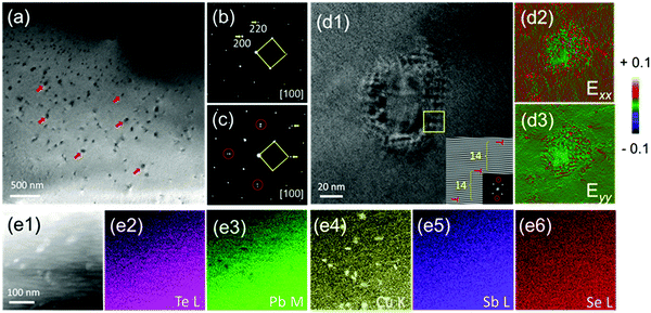 |
| | Fig. 4 Nanoprecipitates in Cu3Pb100Sb3Te100Se6: (a) low magnification bright-field TEM image, with red arrows marking some of the precipitates; electron diffraction along [100] obtained from (b) a small local region that is almost free from nanoprecipitates and (c) a relatively larger region that contains considerable nanoprecipitates. The splitting spots in (c) show that the nanoprecipitates have a similar cubic structure to the PbTe matrix, although a large lattice mismatch by ∼7% is found; (d1) The HRTEM image of the nano-precipitate. Inset showing the Fast-Fourier-Transform (FFT) image that reveals the presence of dislocations, together with the corresponding diffraction spots chosen marked in red; (d2 and d3) GPA maps of (d1) from horizontal (Exx) and vertical (Eyy) directions; (e1–e6) the ADF image and corresponding EDS element maps of Te, Pb, Cu, Sb and Se, respectively. | |
Fig. 4(d1) displays the high resolution TEM (HRTEM) image of the nanoprecipitates, and the dislocations appear as periodic structures as shown in the Fourier transform image of the inset of Fig. 4(d1), consistent with the lattice mismatch of the splitting diffraction spots in Fig. 4(c). Thus, the lattice distortion could be compensated by forming a semi-coherent interface between the matrix and the precipitates. Geometric phase analysis (GPA) is used to determine lattice distortion with respect to the reference matrix structure, as depicted in Fig. 4(d2 and d3). Fig. 4(e1–e6) are the annular dark-field (ADF) images and the corresponding energy dispersive spectroscopy (EDS) elemental maps. We observed a homogeneous distribution of each element in either the matrix or the precipitates. In particular, it is obvious that the precipitates show a composition that is Pb-poor and Cu-rich.
Crystal structure identification in extra Cu-added CLAST
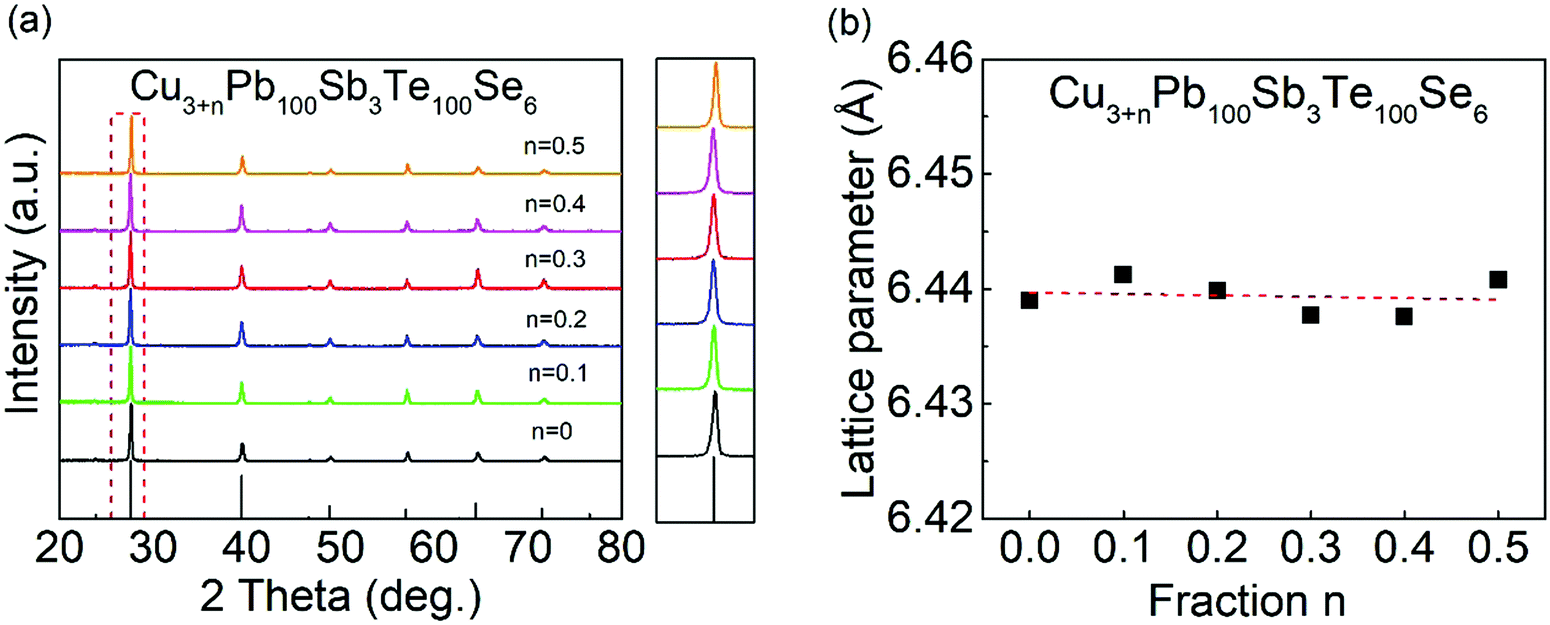
In Fig. 5(a), all the samples can be indexed as a NaCl structure with no distinct secondary phases detected. From the enlarged XRD patterns at ∼27.6 degree, no obvious peak shifts can be observed compared with a CLAST sample, indicating small changes of lattice parameter in extra Cu-added CLAST samples. In Fig. 5(b), the calculated lattice parameters in Cu-added CLAST samples show slight vibrations around ∼6.44 Å.
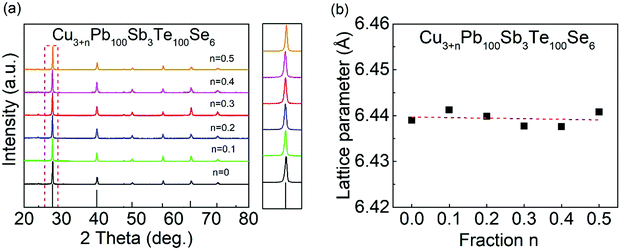 |
| | Fig. 5 Phase identification of Cu3+nPb100Sb3Te100Se6 (n = 0–0.5): (a) powder XRD pattern; (b) lattice parameter. | |
Electrical transport properties in extra Cu-added CLAST
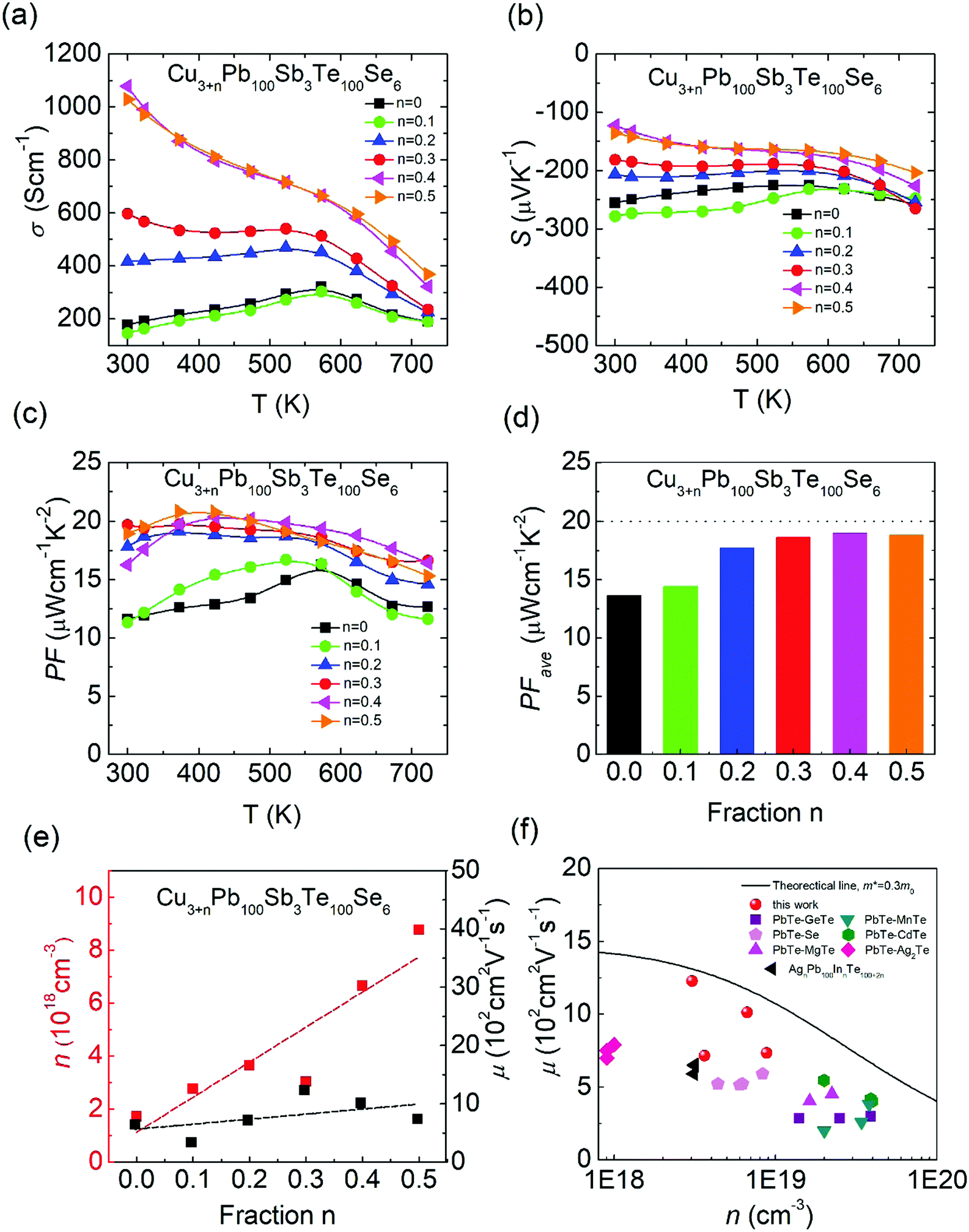
In Fig. 6(a), the extra Cu added in CLAST can largely enhance the electrical transport properties, and the room-temperature electrical conductivity is improved from ∼177.6 S cm−1 in Cu3Pb100Sb3Te100Se6 to ∼1077.3 S cm−1 in Cu3.4Pb100Sb3Te100Se6 through adding a small amount of Cu, n = 0.4. The negative Seebeck coefficient indicates that extra Cu-added CLAST samples are dominated with charge carriers of electrons, and the absolute values of the Seebeck coefficients decrease with increasing Cu content, as shown in Fig. 6(b). The Pisarenko relationship in Fig. S3 (ESI†) unveils that the carrier effective mass in extra Cu-added CLAST samples maintains around ∼0.3m0. The variations of the electrical conductivity and Seebeck coefficient can be commendably accounted for by the enhanced carrier concentration, as shown in Fig. 6(e). In Fig. 6(e), the Hall measurement shows that carrier concentration manifests an obvious upward trend with an increasing amount of Cu, indicating that Cu atoms form massive interstitials to work as a donor in CLAST rather than the hole-doping by Cu in Pb sites, similar as Ag works in AgnPb100InnTe100+2n (LIST) samples.39 Additionally, the carrier mobility of Cu3+nPb100Sb3Te100Se6 is generally higher than that of other n-type PbTe systems (PbTe–GeTe,50 PbTe–Se,51 PbTe–MgTe,52 PbTe–MnTe,53 PbTe–CdTe,54 PbTe–Ag2Te,55 AgnPb100InnTe100+2n39), as shown in Fig. 6(f). It is well known that carrier concentration and carrier mobility are two competing parameters, however, it is very interesting that Cu addition improves both carrier concentration and carrier mobility, which may be related to the interstitials causing weak scattering on carriers56 and compensating Pb vacancies.57 Combining improved electrical conductivity and reduced Seebeck coefficient over the wide temperature, the power factor of Cu-added CLAST is almost two times larger than CLAST samples across the whole temperature range, and the maximum power factor reaches ∼20.4 μW cm−1 K−2 for Cu3.4Pb100Sb3Te100Se6 in Fig. 6(c). The power factor at low temperature is superior to other n-type PbTe systems, such as La-doped PbTe–Ag2Te,58 I-doped PbTe–MgTe,52 PbTe–InSb,59etc. As we know, good electrical transport properties of materials are determined by the average power factor value PFave, calculated as:60| |  | (1) |
where Tc is the cold-end temperature (300 K), and Th is the hot-end temperature (723 K). As shown in Fig. 6(d), the PFave of Cu3+nPb100Sb3Te100Se6 (n = 0.1–0.5) reaches a much higher value, compared with Cu3Pb100Sb3Te100Se6. Therefore, by virtue of improved carrier concentration and carrier mobility, CLAST with added Cu can exhibit an outstanding electrical transport performance.
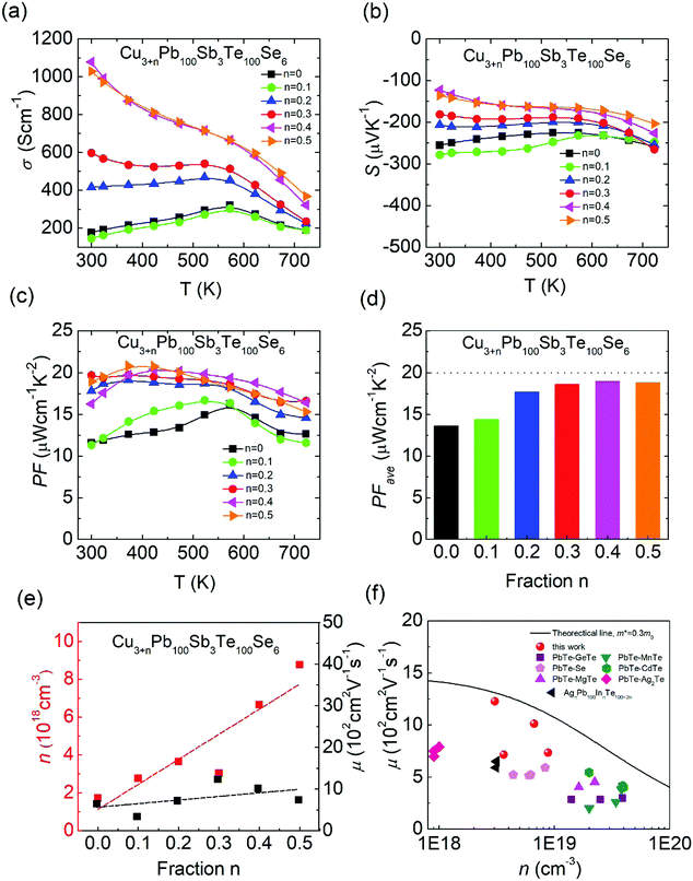 |
| | Fig. 6 Electrical transport properties of Cu3+nPb100Sb3Te100Se6 (n = 0–0.5): (a) electrical conductivity; (b) Seebeck coefficient; (c) power factor; (d) average power factor; (e) carrier concentration and carrier mobility at room temperature; and (f) carrier mobility as a function of carrier concentration at room temperature (PbTe–GeTe,50 PbTe–Se,51 PbTe–MgTe,52 PbTe–MnTe,53 PbTe–CdTe,54 PbTe–Ag2Te,55 AgnPb100InnTe100+2n39). | |
Microstructures in extra Cu-added CLAST
To further examine the location of Cu atoms in the extra Cu-added CLAST sample, we utilized aberration-corrected high-angle annular dark-field scanning transmission electron microscopy (HAADF-STEM) analysis. Two types of atom structures are observed in the Cu3+nPb100Sb3Te100Se6 sample along the [100] zone axis, one shows an atom structure projection that is similar to that of PbTe (cf.Fig. 7(a)), and another displays the existence of Cu interstitials (cf.Fig. 7(b)). The detailed atom arrangement is exemplified in the magnified HAADF image (cf.Fig. 7(c)). Noticeably, the Cu interstitials randomly disperse in the CLAST lattice because of their strong vibrations,57 which can contribute to intensified phonon scattering and then low lattice thermal conductivity. The additional peaks corresponding to Cu interstitials can also be clearly observed in Fig. 7(d).
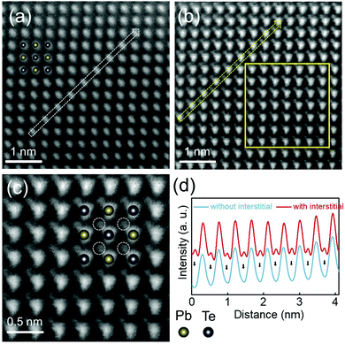 |
| | Fig. 7 Atom structure observation of Cu3.3Pb100Sb3Te100Se6. HAADF images obtained from regions (a) without and (b) with Cu interstitial atoms along the [100] zone axis; (c) enlarged image showing Cu interstitial atoms from the marked regions in (b); and (d) intensity scan profiles obtained from the ADF images, as indicated by hollow arrows shown in (a) and (b), respectively. Inset of (c) shows the schematic atom structure of the CLAST with Cu interstitials, which is labeled by white circles. The arrowed peaks in (d) mark the additional peaks corresponding to Cu interstitials. | |
Thermal transport properties in extra Cu-added CLAST
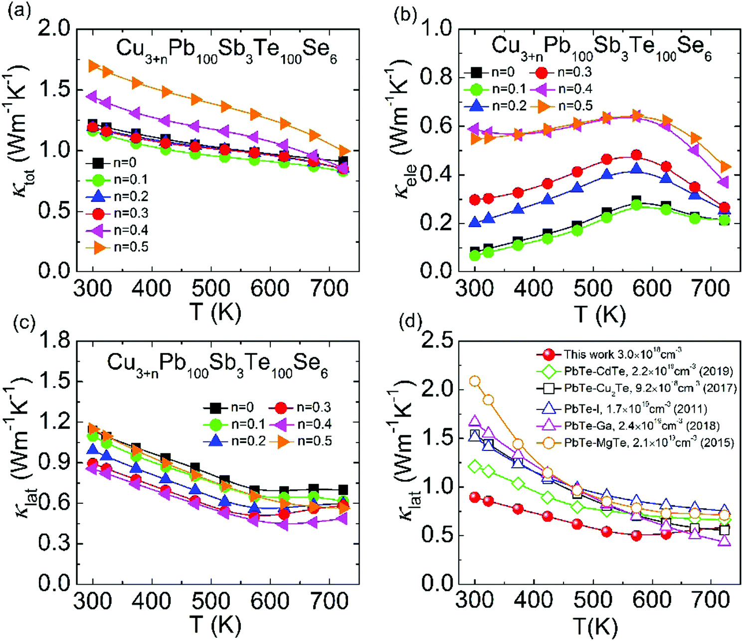
As depicted in Fig. 8(a), the total thermal conductivity is almost unchanged when n < 0.3 and begins to increase when n > 0.3, which comes from the promoted electronic thermal conductivity. In Fig. 8(b), the increased electronic thermal conductivity is in agreement with the electrical conductivity in Fig. 8(a) because of the increasing carrier concentration. In contrast, the lattice thermal conductivity shows a further obvious reduction with Cu added in Fig. 8(c), and the minimum lattice thermal conductivity decreases sharply to ∼0.44 W m−1 K−1 at 623 K in Cu3.4Pb100Sb3Te100Se6, which is extremely close to the minimum theoretical value of PbTe (∼0.36 W m−1 K−1). The suppressed lattice thermal conductivity is indicative of local lattice distortion with Cu atoms, which enhances phonon scattering. Meanwhile, the lattice thermal conductivity exhibits an upward trend above 623 K, which originates from the phase transition of Cu-containing phases and the slightly bipolar diffusion in CLAST samples.61,62 Then, we compared the lattice thermal conductivity of Cu3.4Pb100Sb3Te100Se6 to that of other high-ZT n-type PbTe, such as PbTe–CdTe,54 PbTe–Cu2Te,57 PbTe–I,63 PbTe–Ga,41 and PbTe–MgTe.52 It is obviously noticed that the lattice thermal conductivity of Cu3.3Pb100Sb3Te100Se6 is relatively low compared with others, especially at low temperature. This comes from the superimposed effects of nanoprecipitates and interstitials. Other thermoelectric parameters, including Lorenz number L, heat capacity Cp, thermal diffusivity D, and sample density ρ, are shown in Fig. S4 (ESI†).
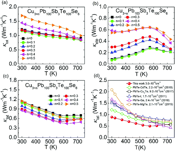 |
| | Fig. 8 Thermal transport properties of Cu3+nPb100Sb3Te100Se6 (n = 0–0.5): (a) total thermal conductivity; (b) electronic thermal conductivity; (c) lattice thermal conductivity; (d) comparison of lattice thermal conductivity of n-type PbTe (PbTe–CdTe,54 PbTe–Cu2Te,57 PbTe–I,63 PbTe–Ga,41 PbTe–MgTe52). | |
ZT values
To evaluate the comprehensive effects of hierarchical structures, precipitates and interstitials, on thermoelectric performance in CLAST samples, the minimum lattice thermal conductivity (κlat) and ratio of carrier mobility to lattice thermal conductivity (μ/κlat) are shown in Fig. 9(a). It is obvious that the lattice thermal conductivity is continuously suppressed through introducing precipitates and interstitials in CLAST. Besides intensifying the phonon scattering, these nanoprecipitates and interstitials can also preserve carrier transport, inducing a large enhancement of μ/κlat in extra Cu-added CLAST. Consequently, these special hierarchical structures, precipitate and interstitials, can contribute to a maximum ZT of ∼0.5 at 300 K and of ∼1.4 at 723 K in Cu3.3Pb100Sb3Te100Se6, as shown in Fig. 9(b). When making a comparison for the room-temperature carrier mobility and lattice thermal conductivity in CLAST with others,39,41,44,45,50,52–55,57,64,65 it is found that the CLAST sample shows a superior performance through balancing the phonon and carrier transports, as shown in Fig. 9(c). These special hierarchical structures in CLAST make its thermoelectric performance competitive to other high-performance n-type PbTe-based materials, especially at a low temperature range, shown in Fig. 9(d). The average ZT values (ZTave) are also calculated as:66–68| | 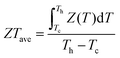 | (2) |
where Tc is the cold-end temperature (300 K), and Th is the hot-end temperature (723 K). In Fig. S5 (ESI†), a remarkably high ZTave of ∼0.94 is achieved in Cu3.3Pb100Sb3Te100Se6 from 300 K to 723 K due to outstanding ZT values in the low temperature range.
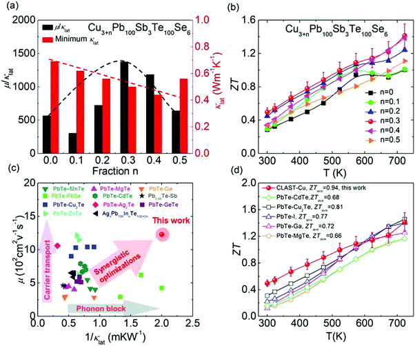 |
| | Fig. 9 Comparisons of thermoelectric parameters of CLAST and others: (a) ratio of carrier mobility to lattice thermal conductivity (μ/κlat) at room temperature; (b) ZT values of Cu3+nPb100Sb6Te100Se6 (n = 0–0.5); (c) diagram of μ and 1/κlat (PbTe–MnTe,53 PbTe–PbSe,64 PbTe–Cu2Te,57 PbTe–ZnTe,44 PbTe–MgTe,52 PbTe–CdTe,54 PbTe–Ag2Te,55 PbTe–Ga,41 Pb0.98Te–Sb,65 PbTe–GeTe,50 AgnPb100InTe100+2n39); (d) comparisons of ZT values in n-type PbTe (PbTe–CdTe,54 PbTe–Cu2Te,57 PbTe–I,63 PbTe–Ga,41 PbTe–MgTe52). | |
Conclusions
In summary, a maximum ZT ∼ 0.5 at 300 K and ∼1.4 at 723 K, and average ZT ∼ 0.94 at 300–723 K are achieved in an n-type CLAST sample. Its high thermoelectric transport properties are mainly attributed to the hierarchical structures of nanoprecipitates and interstitials, which can well balance the phonon and carrier transport. The nanoprecipitates firstly are formed in the CLAST sample with ternary compound CuSbSe2 alloying, which can intensify phonon scattering to largely depress the lattice thermal conductivity. With extra Cu added in CLAST, massive interstitials can be observed, and these Cu interstitials can well optimize the carrier concentration and carrier mobility, and simultaneously further lower the lattice thermal conductivity. These special hierarchical structures in CLAST finally make its thermoelectric performance obviously higher than other n-type PbTe-based thermoelectric materials. This work puts forward an effective strategy to synergistically optimize phonon and carrier transports through designing hierarchical structures, and also proves that the interstitials are of great importance to enhance the thermoelectric performance through balancing electrical and thermal transport.
Author contribution
Siqi Wang, Yu Xiao and Li-Dong Zhao designed the research; Siqi Wang compounded the samples and made thermoelectric performance tests; Yongjin Chen, Xiang Gao, Shang Peng and Tao Hong performed TEM characterization; Siqi Wang, Dongyang Wang, Zhi Yang and Yuejun Sun analyzed data and drew diagrams. Siqi Wang, Yu Xiao and Xiang Gao wrote the manuscript and all authors edited the manuscript.
Conflicts of interest
There are no conflicts to declare.
Acknowledgements
This work was supported by the National Key Research and Development Program of China (2018YFA0702100 and 2018YFB0703600), the National Natural Science Foundation of China (51772012 and 51671015), Beijing Natural Science Foundation (JQ18004), Shenzhen Peacock Plan team (KQTD2016022619565991), the National Postdoctoral Program for Innovative Talents (BX20190028 and BX20200028), 111 Project (B17002) and Postdoctoral Science Foundation of China (2019M660399). L. D. Z. is thankful for the support from the National Science Fund for Distinguished Young Scholars (51925101) and the high performance computing (HPC) resources at Beihang University.
References
- Y. Xiao and L.-D. Zhao, Science, 2020, 367, 1196–1197 CrossRef CAS PubMed.
- L.-D. Zhao, V. P. Dravid and M. G. Kanatzidis, Energy Environ. Sci., 2014, 7, 251–268 RSC.
- X. L. Shi, J. Zou and Z. G. Chen, Chem. Rev., 2020, 120, 7399–7515 CrossRef CAS PubMed.
- Y. M. Zhou and L. D. Zhao, Adv. Mater., 2017, 29, 1702676 CrossRef PubMed.
- D. Y. Wang, Z. W. Huang, Y. Zhang, L. J. Hao, G. T. Wang, S. H. Deng, H. L. Wang, J. Chen, L. H. He, B. Xiao, Y. D. Xu, S. J. Pennycook, H. J. Wu and L. D. Zhao, Sci. China Mater., 2020, 63, 1759–1768 CrossRef CAS.
- J. F. Li, Y. Pan, C. F. Wu, F. H. Sun and T. R. Wei, Sci. China: Technol. Sci., 2017, 60, 1347–1364 CrossRef.
- M. G. Kanatzidis, Chem. Mater., 2010, 22, 648–659 CrossRef CAS.
- B.-C. Qin, Y. Xiao, Y.-M. Zhou and L.-D. Zhao, Rare Met., 2017, 37, 343–350 CrossRef.
- Y. Xiao and L.-D. Zhao, npj Quantum Mater., 2018, 3, 55 CrossRef.
- A. T. Duong, V. Q. Nguyen, G. Duvjir, V. T. Duong, S. Kwon, J. Y. Song, J. K. Lee, J. E. Lee, S. Park, T. Min, J. Lee, J. Kim and S. Cho, Nat. Commun., 2016, 7, 13713 CrossRef CAS PubMed.
- W. K. He, D. Y. Wang, H. J. Wu, Y. Xiao, Y. Zhang, D. S. He, Y. Feng, Y. J. Hao, J. F. Dong, R. Chetty, L. J. Hao, D. F. Chen, J. F. Qin, Q. Yang, X. Li, J. M. Song, Y. C. Zhu, W. Xu, C. L. Niu, X. Li, G. T. Wang, C. Liu, M. Ohta, S. J. Pennycook, J. Q. He, J. F. Li and L.-D. Zhao, Science, 2019, 365, 1418–1424 CrossRef CAS PubMed.
- H. S. Dow, M. Na, S. J. Kim and J. W. Lee, J. Mater. Chem. C, 2019, 7, 3787–3794 RSC.
- L. You, J. Y. Zhang, S. S. Pan, Y. Jiang, K. Wang, J. Yang, Y. Z. Pei, Q. Zhu, M. T. Agne, G. J. Snyder, Z. F. Ren, W. Q. Zhang and J. Luo, Energy Environ. Sci., 2019, 12, 3089–3098 RSC.
- L. P. Hu, T. J. Zhu, X. H. Liu and X. B. Zhao, Adv. Funct. Mater., 2014, 24, 5211–5218 CrossRef CAS.
- J. Shuai, Y. Sun, X. J. Tan and T. Mori, Small, 2020, 16, 1906921 CrossRef CAS PubMed.
- G. Z. Xie, Z. Li, T. T. Luo, H. Bai, J. C. Sun, Y. Xiao, L.-D. Zhao, J. S. Wu, G. J. Tan and X. F. Tang, Nano Energy, 2020, 69, 104395 CrossRef CAS.
- T. J. Slade, J. A. Grovogui, J. J. Kuo, S. Anand, T. P. Bailey, M. Wood, C. Uher, G. J. Snyder, V. P. Dravid and M. G. Kanatzidis, Energy Environ. Sci., 2020, 13, 1509–1518 RSC.
- W. W. Qu, X. X. Zhang, B. F. Yuan and L. D. Zhao, Rare Met., 2018, 37, 79–94 CrossRef CAS.
- D. Li, H. W. Ming, J. M. Li, B. Jabar, W. Xu, J. Zhang and X. Y. Qin, ACS Appl. Mater. Interfaces, 2020, 12, 3886–3892 CrossRef CAS PubMed.
- B. Xiang, J. Liu, J. Yan, M. Xia, Q. Zhang, L. Chen, J. Li, X. Y. Tan, Q. Yan and Y. Wu, J. Mater. Chem. A, 2019, 7, 18458–18467 RSC.
- C. Chang and L. D. Zhao, Mater. Today Phys., 2018, 4, 50–57 CrossRef.
- J. Li, J. H. Sui, Y. L. Pei, C. Barreteau, D. Berardan, N. Dragoe, W. Cai, J. Q. He and L.-D. Zhao, Energy Environ. Sci., 2012, 5, 8543–8547 RSC.
- S. N. Guin and K. Biswas, J. Mater. Chem. C, 2015, 3, 10415–10421 RSC.
- D. Wu, Y. L. Pei, Z. Wang, H. J. Wu, L. Huang, L. D. Zhao and J. Q. He, Adv. Funct. Mater., 2014, 24, 7763–7771 CrossRef CAS.
- G. J. Tan, F. Y. Shi, S. Q. Hao, H. Chi, L.-D. Zhao, C. Uher, C. Wolverton, V. P. Dravid and M. G. Kanatzidis, J. Am. Chem. Soc., 2015, 137, 5100–5112 CrossRef CAS PubMed.
- C. J. Zhou, Y. Yu, Y. K. Lee, O. Cojocaru-Miredin, B. Yoo, S. P. Cho, J. Im, M. Wuttig, T. Hyeon and I. Chung, J. Am. Chem. Soc., 2018, 140, 15535–15545 CrossRef CAS PubMed.
- S. Sarkar, X. Zhang, S. Hao, X. Hua, T. P. Bailey, C. Uher, C. Wolverton, V. P. Dravid and M. G. Kanatzidis, ACS Energy Lett., 2018, 3, 2593–2601 CrossRef CAS.
- Y. L. Pei, C. Chang, Z. Wang, M. J. Yin, M. H. Wu, G. J. Tan, H. J. Wu, Y. X. Chen, L. Zheng, S. K. Gong, T. J. Zhu, X. B. Zhao, L. Huang, J. Q. He, M. G. Kanatzidis and L. D. Zhao, J. Am. Chem. Soc., 2016, 138, 16364–16371 CrossRef CAS PubMed.
- A. D. LaLonde, Y. Z. Pei, H. Wang and G. J. Snyder, Mater. Today, 2011, 14, 526–532 CrossRef CAS.
- L. W. Fu, J. Cui, Y. Yu, Y. Huang, Y. F. Wang, Y. Chen and J. Q. He, J. Mater. Chem. A, 2019, 7, 6304–6311 RSC.
- X. Zhang, D. Y. Wang, H. J. Wu, M. J. Yin, Y. L. Pei, S. K. Gong, L. Huang, S. J. Pennycook, J. Q. He and L.-D. Zhao, Energy Environ. Sci., 2017, 10, 2420–2431 RSC.
- G. J. Tan, C. C. Stoumpos, S. Wang, T. P. Bailey, L.-D. Zhao, C. Uher and M. G. Kanatzidis, Adv. Energy Mater., 2017, 7, 1700099 CrossRef.
- G. J. Tan, F. Y. Shi, S. Q. Hao, L.-D. Zhao, H. Chi, X. M. Zhang, C. Uher, C. Wolverton, V. P. Dravid and M. G. Kanatzidis, Nat. Commun., 2016, 7, 12167 CrossRef CAS PubMed.
- D. Wu, L.-D. Zhao, X. Tong, W. Li, L. J. Wu, Q. Tan, Y. L. Pei, L. Huang, J. F. Li, Y. M. Zhu, M. G. Kanatzidis and J. Q. He, Energy Environ. Sci., 2015, 8, 2056–2068 RSC.
- H. J. Wu, L.-D. Zhao, F. S. Zheng, D. Wu, Y. L. Pei, X. Tong, M. G. Kanatzidis and J. Q. He, Nat. Commun., 2014, 5, 4515 CrossRef CAS PubMed.
- S. Q. Wang, Z. Yang, Y. J. Sun, Y. Xiao and L.-D. Zhao, J. Alloys Compd., 2020, 815, 152463 CrossRef CAS.
- K. Q. Zhang, H. C. Wang, W. B. Su, T. Wang, X. Wang, T. T. Chen, T. C. Huo, F. Dang, M. Y. Dong, C. L. Wang, B. B. Dong and Z. H. Guo, J. Phys. D: Appl. Phys., 2020, 53, 245501 CrossRef CAS.
- Q. Zhang, Q. C. Song, X. Y. Wang, J. Y. Sun, Q. Zhu, K. Dahal, X. Lin, F. Cao, J. W. Zhou, S. Chen, G. Chen, J. Mao and Z. F. Ren, Energy Environ. Sci., 2018, 11, 933–940 RSC.
- Y. Xiao, H. J. Wu, D. Y. Wang, C. L. Niu, Y. L. Pei, Y. Zhang, I. Spanopoulos, I. T. Witting, X. Li, S. J. Pennycook, G. J. Snyder, M. G. Kanatzidis and L.-D. Zhao, Adv. Energy Mater., 2019, 9, 1900414 CrossRef.
- X. L. Su, S. Q. Hao, T. P. Bailey, S. Wang, I. Hadar, G. J. Tan, T.-B. Song, Q. J. Zhang, C. Uher, C. Wolverton, X. F. Tang and M. G. Kanatzidis, Adv. Energy Mater., 2018, 8, 1800659 CrossRef.
- Z. S. Wang, G. Y. Wang, R. F. Wang, X. Y. Zhou, Z. Y. Chen, C. Yin, M. J. Tang, Q. Hu, J. Tang and R. Ang, ACS Appl. Mater. Interfaces, 2018, 10, 22401–22407 CrossRef CAS PubMed.
- Y. Xiao, D. Wang, B. Qin, J. Wang, G. Wang and L.-D. Zhao, J. Am. Chem. Soc., 2018, 140, 13097–13102 CrossRef CAS PubMed.
- Y. Xiao, D. Wang, Y. Zhang, C. Chen, S. Zhang, K. Wang, G. Wang, S. J. Pennycook, G. J. Snyder, H. Wu and L.-D. Zhao, J. Am. Chem. Soc., 2020, 142, 4051–4060 CrossRef CAS PubMed.
- P. K. Rawat, B. Paul and P. Banerji, ACS Appl. Mater. Interfaces, 2014, 6, 3995–4004 CrossRef CAS PubMed.
- K. Ahn, M. K. Han, J. Q. He, J. Androulakis, S. Ballikaya, C. Uher, V. P. Dravid and M. G. Kanatzidis, J. Am. Chem. Soc., 2010, 132, 5227–5235 CrossRef CAS PubMed.
- K. Biswas, J. Q. He, G. Y. Wang, S. H. Lo, C. Uher, V. P. Dravid and M. G. Kanatzidis, Energy Environ. Sci., 2011, 4, 4675–4684 RSC.
- S. N. Girard, T. C. Chasapis, J. Q. He, X. Y. Zhou, E. Hatzikraniotis, C. Uher, K. M. Paraskevopoulos, V. P. Dravid and M. G. Kanatzidis, Energy Environ. Sci., 2012, 5, 8716–8725 RSC.
- S. Ballikaya, H. Chi, J. R. Salvador and C. Uher, J. Mater. Chem. A, 2013, 1, 12478–12484 RSC.
- S. Mukherjee, R. Parasuraman, A. M. Umarji, G. Rogl, P. Rogl and K. Chattopadhyay, J. Alloys Compd., 2020, 817, 152729 CrossRef CAS.
- Z.-Z. Luo, X. M. Zhang, X. Hua, G. J. Tan, T. P. Bailey, J. W. Xu, C. Uher, C. Wolverton, V. P. Dravid, Q. Y. Yan and M. G. Kanatzidis, Adv. Funct. Mater., 2018, 28, 1801617 CrossRef.
- K. M. Zhang, Q. H. Zhang, L. J. Wang, W. Jiang and L. D. Chen, J. Alloys Compd., 2017, 725, 563–572 CrossRef CAS.
- P. Jood, M. Ohta, M. Kunii, X. Hu, H. Nishiate, A. Yamamoto and M. G. Kanatzidis, J. Mater. Chem. C, 2015, 3, 10401–10408 RSC.
- Y. Xiao, H. J. Wu, J. Cui, D. Y. Wang, L. W. Fu, Y. Zhang, Y. Chen, J. Q. He, S. J. Pennycook and L.-D. Zhao, Energy Environ. Sci., 2018, 11, 2486–2495 RSC.
- G. J. Tan, X. M. Zhang, S. Q. Hao, H. Chi, T. P. Bailey, X. L. Su, C. Uher, V. P. Dravid, C. Wolverton and M. G. Kanatzidis, ACS Appl. Mater. Interfaces, 2019, 11, 9197–9204 CrossRef CAS PubMed.
- Y. Z. Pei, A. F. May and G. J. Snyder, Adv. Energy Mater., 2011, 1, 291–296 CrossRef CAS.
- Y. X. Qin, Y. Xiao and L.-D. Zhao, APL Mater., 2020, 8, 010901 CrossRef CAS.
- Y. Xiao, H. J. Wu, W. Li, M. J. Yin, Y. L. Pei, Y. Zhang, L. W. Fu, Y. X. Chen, S. J. Pennycook, L. Huang, J. He and L.-D. Zhao, J. Am. Chem. Soc., 2017, 139, 18732–18738 CrossRef CAS PubMed.
- Y. Z. Pei, J. Lensch-Falk, E. S. Toberer, D. L. Medlin and G. J. Snyder, Adv. Funct. Mater., 2011, 21, 241–249 CrossRef CAS.
- J. Zhang, D. Wu, D. S. He, D. Feng, M. J. Yin, X. Y. Qin and J. Q. He, Adv. Mater., 2017, 29, 1703148 CrossRef PubMed.
- H. S. Kim, W. S. Liu, G. Chen, C. W. Chua and Z. F. Ren, Proc. Natl. Acad. Sci. U. S. A., 2015, 112, 8205–8210 CrossRef CAS PubMed.
- L.-D. Zhao, H. J. Wu, S. Q. Hao, C. I. Wu, X. Y. Zhou, K. Biswas, J. Q. He, T. P. Hogan, C. Uher, C. Wolverton, V. P. Dravid and M. G. Kanatzidis, Energy Environ. Sci., 2013, 6, 3346–3355 RSC.
- Y. L. Pei and Y. Liu, J. Alloys Compd., 2012, 514, 40–44 CrossRef CAS.
- A. D. LaLonde, Y. Z. Pei and G. J. Snyder, Energy Environ. Sci., 2011, 4, 2090–2096 RSC.
- H. Sun, B. W. Cai, P. Zhao, F. R. Yu, L. Zhang, D. L. Yu, Y. J. Tian and B. Xu, J. Alloys Compd., 2019, 791, 786–791 CrossRef CAS.
- H. T. Liu, Z. Y. Chen, C. Yin, B. Q. Zhou, B. Liu and R. Ang, Appl. Phys. A: Mater. Sci. Process., 2019, 125, 225 CrossRef.
- B. C. Qin, Y. Zhang, D. Y. Wang, Q. Zhao, B. C. Gu, H. J. Wu, H. J. Zhang, B. J. Ye, S. J. Pennycook and L.-D. Zhao, J. Am. Chem. Soc., 2020, 142, 5901–5909 CrossRef CAS PubMed.
- X. Qian, H. J. Wu, D. Y. Wang, Y. Zhang, J. F. Wang, G. T. Wang, L. Zheng, S. J. Pennycook and L.-D. Zhao, Energy Environ. Sci., 2019, 12, 1969–1978 RSC.
- B. Qin, D. Wang, W. He, Y. Zhang, H. Wu, S. J. Pennycook and L. D. Zhao, J. Am. Chem. Soc., 2019, 141, 1141–1149 CrossRef CAS PubMed.
Footnotes |
| † Electronic supplementary information (ESI) available. See DOI: 10.1039/d0ee03459b |
| ‡ These authors contributed equally to this work. |
|
| This journal is © The Royal Society of Chemistry 2021 |
Click here to see how this site uses Cookies. View our privacy policy here. 
 b,
Yongjin
Chen
c,
Shang
Peng
c,
Dongyang
Wang
b,
Tao
Hong
b,
Zhi
Yang
a,
Yuejun
Sun
ad,
Xiang
Gao
*c and
Li-Dong
Zhao
b,
Yongjin
Chen
c,
Shang
Peng
c,
Dongyang
Wang
b,
Tao
Hong
b,
Zhi
Yang
a,
Yuejun
Sun
ad,
Xiang
Gao
*c and
Li-Dong
Zhao