
Computational investigation of a switchable emulsion stabilized by the mixture of a surfactant and tertiary amine†
Yue
Wang
a,
Hui
Yan
 *a,
Xiujuan
Zhong
a and
Shiling
Yuan
*b
*a,
Xiujuan
Zhong
a and
Shiling
Yuan
*b
aSchool of Pharmacy, Liaocheng University, Liaocheng 252059, China. E-mail: yanhui@lcu.edu.cn
bKey Lab of Colloid and Interface Chemistry, Shandong University, Jinan 250199, China. E-mail: shilingyuan@sdu.edu.cn
First published on 17th November 2020
Abstract
Molecular dynamics simulations were performed to investigate the CO2-responsiveness of an oil-in-water (O/W) emulsion stabilized by sodium oleate (NaOA) with a tertiary amine additive, named pentamethyl diethylenetriamine (PMA). The simulated results were in accordance with the experimental observations. That is, the surfactant NaOA itself can stabilize dodecane/water emulsions in aqueous solution, while the CO2-reponsiveness was strongly related to the added PMA. The electroneutral PMA molecules preferred to be located in the core region of the droplets. Thus, under the same conditions, the size of the droplet containing PMA is predictably larger than that without PMA. The increased extent of the charged surfactant headgroups distribution can increase the electrostatic repulsion between the droplets in the emulsion solution, which is the important reason why a much more stable emulsion is obtained by adding PMA. When PMA molecules were protonated to PMA2+ by bubbling CO2, they migrated from the interior to the surface of the droplets under electrostatic attraction, forming ion pairs with OA−. The binding between PMA2+ and OA− made the distribution of the surfactants very concentrated on the droplet surface, leading to large hydrophobic areas exposed to water. Besides, the hydration interactions of OA− headgroups decreased because they were covered by PMA2+. The calculated potential of mean force (PMF) confirmed that the electrostatic repulsion between droplets was crucial for the emulsion stabilization.
Introduction
Environmental stimuli-responsive or “switchable” surfactants have been widely used to prepare emulsions, because they are usually eco-friendly and recyclable.1,2 Stimuli-responsive surfactants can be classified into two categories. One is the surfactant itself containing functional groups, which are responsive to the changes of the environmental factors.1–5 The other one is the agents added to surfactant assemblies having stimuli-responsive groups.6–11 Through controlling the external conditions, the structural properties of surfactants or additives could change. Therefore, controllable emulsification and demulsification can be achieved as desired.The switchable surfactants can be further classified on the basis of the external stimuli, such as CO2,1,3 solution pH,12,13 temperature,14,15 UV light,11,16 and redox reagents.5,17 Compared with other triggers, CO2 is nontoxic, inexpensive and easily removable. In 2010, Jessop and co-workers first developed a CO2-switchable cationic surfactant using long-chain alkyl amidines.1 Since then, the CO2-controlled surfactants have attracted wide attention in many scientific and industrial fields. Many new types of stimuli-responsive surfactants and additives have been developed and applied in many areas, such as emulsion/demulsification,10,18–23 soil remediation,24 and pollution adsorption.25
Recently, Lu and co-workers used a series of water-soluble tertiary amines (TAs) with a traditional surfactant (sodium oleate, NaOA) to prepare emulsions.18,19 Upon bubbling CO2 into the solution, TAs converted into bicarbonate salts and formed ion pairs with NaOA, resulting in demulsification. Removing CO2 from the solution by introducing N2 can reverse the process and the emulsion formed again. The effects of structure factors on the CO2-responsiveness of an emulsion, including the number of tertiary amine groups and the locations of a hydroxyl group, were also investigated. It is found that increasing the tertiary amine groups would help to stabilize the emulsion and a faster demulsification was achieved when bubbling N2.
According to the experimental observations and the proposed mechanisms underlying the reversible emulsion/demulsification process, the binding between protonated TAs and surfactants could be responsible for the demulsification. However, the switchable hydration properties of TAs, as well as the effect of their structural characteristics on the reversible performance, still warrant a further detailed investigation, especially at the molecular level. In addition, systematic theoretical studies on the switchable surfactant/additive systems could help to understand the molecular mechanism behind the specific effects of different additives on the reversible performance. To achieve this goal, molecular dynamics (MD) simulations are an effective approach to provide supplemental and microscopic insights for the experimental observations.
During the past few years, many theoretical studies have been devoted to gaining insights into the behaviors of multiphase emulsion systems.26–34 Limited to the modeling scale and computational ability, the dissipative particle dynamics (DPD) method is suitable for investigating the phase behavior on the mesoscale.31,33,34 Although DPD can provide useful information on the interfacial and structural properties of the systems on a large scale, it cannot capture the intermolecular interactions at the atomic level. The classic MD method exhibits good performance to observe the interactions between atoms, but it is still a challenge to simulate the target system with large dimensions and a long time-scale. For instance, the diameter of microemulsion droplets is usually in a range of 10–100 nm. Thus, it is very time consuming to observe some special phenomena of the emulsion system, such as droplets’ coalescence, using the classic MD method with large dimensions. The common practice using classic MD to investigate emulsion systems is to construct a water/oil interface.30,32 However, the coalescence or the demulsification process could not be directly visualized. Thus, the microscopic insights into these processes will not be appropriately gained.
The main objectives of this work were to explore the mechanism behind the emulsification/demulsification processes with a CO2-switchable surfactant/additive system. On the basis of the experiments reported by Lu et al.,18 a representative TA named pentamethyl diethylenetriamine (PMA) was selected as the additive to the emulsion, because of its high performance in stabilizing or breaking emulsions. We performed MD simulations to study the reversible emulsion/demulsification process by surfactant NaOA with PMA. The formation of an emulsion by this surfactant system was studied in detail. The demulsification induced by transition from PMA to protonated PMA2+ ions was then simulated. During this process, we focused on the intermolecular interactions between the surfactant and PMA. Potential of mean force (PMF) was calculated to quantitatively determine the factors that play a role in stabilizing or breaking the emulsion.
Experimental
A series of simulated systems were modeled to study the formation or demulsification of the CO2-controlled oil-in-water emulsion. We first simulated the emulsification of dodecane by the NaOA surfactant solution (system I). This system was constructed by randomly inserting 100 OA− and 300 dodecane monomers into a cubic box with dimensions of 103 nm3, containing about 27![[thin space (1/6-em)]](https://www.rsc.org/images/entities/char_2009.gif) 000 water molecules. The setting of the surfactant–oil proportion was not strict. On the one hand, the volume ratio of oil to water should not be very large. Otherwise, oil–water separation would be observed from the MD simulations. On the other hand, an O/W emulsion was usually formed by adding a small amount of surfactant into the oil–water mixture. Thus, the number of surfactants in this work was set to be less than that of oil molecules. In the Discussion section, the reason for selecting 1:3 as the surfactant–oil proportion is explained. The MD results indicated that the proportion set was suitable to reflect the experimental phenomenon. Besides, in these simulated systems, all NaOA molecules were present in their ionized form OA− and the small amount of hydrophilic oleic acid HOA was ignored for the sake of simplicity.
000 water molecules. The setting of the surfactant–oil proportion was not strict. On the one hand, the volume ratio of oil to water should not be very large. Otherwise, oil–water separation would be observed from the MD simulations. On the other hand, an O/W emulsion was usually formed by adding a small amount of surfactant into the oil–water mixture. Thus, the number of surfactants in this work was set to be less than that of oil molecules. In the Discussion section, the reason for selecting 1:3 as the surfactant–oil proportion is explained. The MD results indicated that the proportion set was suitable to reflect the experimental phenomenon. Besides, in these simulated systems, all NaOA molecules were present in their ionized form OA− and the small amount of hydrophilic oleic acid HOA was ignored for the sake of simplicity.
The effect of PMA on the emulsion stabilized by NaOA was investigated by performing system II. The initial setup of this system was the same as system I, that is all the substances were randomly distributed at the start state. The molar ratio of PMA/NaOA was set to 1:1, which was consistent with the experimental situation.18 System III was modelled to study the CO2-responsiveness of the NaOA/PMA solution. According to the experimental verification,18 two tertiary amine groups of PMA were protonated after CO2 was bubbled into the solution. Fig. 1 shows the reversible reaction of PMA and PMA2+. The protonated PMA2+ formed an ion pair with OA− through electrostatic interactions, resulting in the demulsification. Thus, system III was built by randomly inserting OA− and PMA2+, along with dodecane monomers into the same cubic box used in system I. Because the amount of hydrophilic oleic acid (HOA) was less after CO2 was introduced into the solution, the protonation of OA was ignored for the sake of simplicity. To investigate the effect of the initial configuration on the simulated results, system IV was performed by inserting PMA2+ into the final configuration of system I, and system V was built by changing all PMA molecules to PMA2+ in the final configuration of system II. The reversible reaction between PMA and PMA2+ was also ignored. Because in the actual situation, CO2 was continuously bubbled into the solution resulting in protonation of PMA. Since we focused on the effect of PMA2+ on the demulsification, the last systems were performed in the absence of PMA molecules. In the PMA2+ systems, HCO3− ions were added to make them electrically neutral. All the simulated systems are summarized in Table S1 in the ESI.† A flowchart showing the relationship among the above systems is also provided in Table S1 (ESI†).
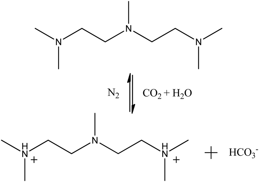 | ||
| Fig. 1 Reversible reaction of PMA and PMA2+.18 | ||
MD simulations were performed using the GROMACS 2019 package.35–38 The GROMOS96 54A7 united-atom force field39 was adopted for the potential function terms to calculate the interatomic interactions. The force field topology files for the components including OA−, PMA, PMA2+, HCO3−, and dodecane were generated from the Automated Topology Builder server.40 Water molecules were described using the simple point charge/extend (SPC/E) model.41 The system energy was first minimized using the steepest descent method. Then, MD simulations were performed under the NPT ensemble at 1 atm and 298 K. The temperature and pressure were controlled using a v-rescale thermostat42 and a Berendsen barostat43 with coupling time constants of 0.1 and 1.0 ps, respectively. During the simulations, bond lengths were constrained using the LINCS method.44 A cutoff distance of 1.2 nm was applied for the short-range pair interactions, and the long-range electrostatic interactions were treated with the particle mesh Ewald method.45 Periodic boundary conditions were applied in all directions. A time step of 2 fs was used in the simulations and trajectories were saved every 200 ps. The simulation times for different systems are listed in Table S1, ESI.† The simulated configurations were displayed using the VMD software.46
Results and discussion
Emulsification by NaOA or the NAOA/PMA mixture
The formation process of an oil-in-water emulsion stabilized by NaOA was analyzed by checking the MD trajectories of system I. To illustrate the formation process, the quantity of droplets formed by OA− and dodecane was counted with time, as shown in Fig. 2a. Several configurations at different moments of the simulation are shown together with the profile in Fig. 2. It can be seen that the adjacent molecules aggregated to form small droplets as soon as the simulation began. Subsequently, these small droplets gradually fused into large ones. At about 42 ns, the number of the aggregated clusters was reduced to two. During the following simulation, the finally formed two droplets kept steady without further droplet coalescence. In the presence of PMA (system II), the aggregation process is similar to that without PMA. As shown in Fig. 2b. The components including OA−, dodecane, and PMA assembled into two stable droplets.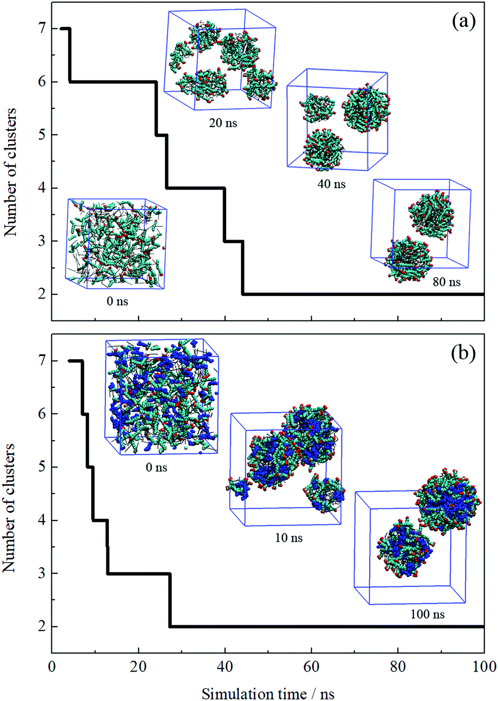 | ||
| Fig. 2 Number of aggregated clusters with time evolution. Several instantaneous configurations selected from MD trajectories of systems I (a) and II (b) are shown together. Dodecane and PMA molecules are shown in black lines and blue VDW models, respectively. The headgroup O atoms and hydrocarbon chains of OA− are shown in red and cyan, respectively. The blue cube represents the periodic boundaries and water molecules and ions are omitted for clarity. | ||
To further check the reproducibility of the observations from the simulated systems, the systems were performed once again. The dynamic processes of the repeated trajectories are shown in Fig. S1 in the ESI† by plotting the number of clusters versus simulation time. These results show good consistency, which verified the reproducibility of the simulation methods. In addition, several additional systems have been performed to compare the effect of the quantity of surfactants on the emulsion (Fig. S2, ESI†). It was found that the surfactants and oil molecules aggregated spontaneously and formed one or more droplets with the surfactants adsorbed on the droplet surface. In the system with a few surfactants, a large droplet formed by OA− and dodecane was observed after 50 ns simulation. But it was insufficient to represent the emulsion only by one droplet. When the number of surfactants is equal to or greater than that of oil molecules, the obtained structures seem to be more like micelles, especially the swollen micelles with oil molecules distributed internally. After comparing each situation, we used the system in which the number of surfactants was set to be less than the oil molecules.
It is worth noting that the size of droplets may be smaller than that in actual experiments, since even the diameter of microemulsion droplets is between 5 and 100 nm. It would exceed the computational capability if the diameter of simulated droplets got bigger. To further verify the results of the simulated systems, the system size was doubled. Take system II for instance, the initial setup of the simulation box was doubled along the z direction, as shown in Fig. S3, ESI.† Correspondingly, the number of components was doubled. After 50 ns simulation, the MD configuration shows that four dispersed droplets formed. This suggests that the simulation setup could qualitatively describe the formation of dispersed droplets regardless of the droplets’ actual diameter.
The equilibrium of the first two systems was determined by calculating the radii of the finally formed two droplets and the distance between them as a function of simulation time. The radius of the droplet was defined by the average distances between headgroup O atoms of OA− and droplet COM (center of mass). Fig. 3 shows that the radii of the individual droplets remained quite stable for a long simulation time after they formed. Although COM distances between the two droplets show larger fluctuations, they kept their distance at around 6.5 nm during the simulations. In addition, the two droplets show no trend toward droplet coalescence judging by the distance variation. These distance profiles reflect that the two simulated systems reached their equilibrium states. Besides, the variation of box lengths during the simulations was checked to ensure the accuracy of the pressure control, as shown in Fig. S4 (ESI†). It can be seen that the fluctuation of box lengths remained steady during the simulations, and there is little difference in density among the systems.
 | ||
| Fig. 3 COM distance between the two obtained droplets from system I (a) and II (b), and their radii plotted as a function of simulation time. | ||
Fig. 2 shows that the droplets formed with the surfactants OA− located at the droplet surface, and oil molecules were wrapped inside the droplets. To further explore the structural properties of the formed droplets, the density distribution probability of the selected atoms was plotted, as shown in Fig. 4. For systems I and II, one of the finally formed two droplets was selected to calculate the number density distribution with respect to the droplet COM. The profiles illustrate that the dodecane molecules were encased inside the droplet, with OA− surfactants adsorbed on the surface. The alkyl chains of the surfactant were inserted into the oil phase under hydrophobic interactions with oil molecules. For system II, the distribution of PMA molecules was represented by the N atoms. It can be seen that all PMA molecules were solubilized into the deep core region of the droplet. Besides, the carboxy groups of surfactants were found to penetrate into the water phase, constituting a hydrophilic shell around the droplet. This hydrophilic shell is considered to help dissolve the oil droplet in the water solution and further stabilize the emulsion.
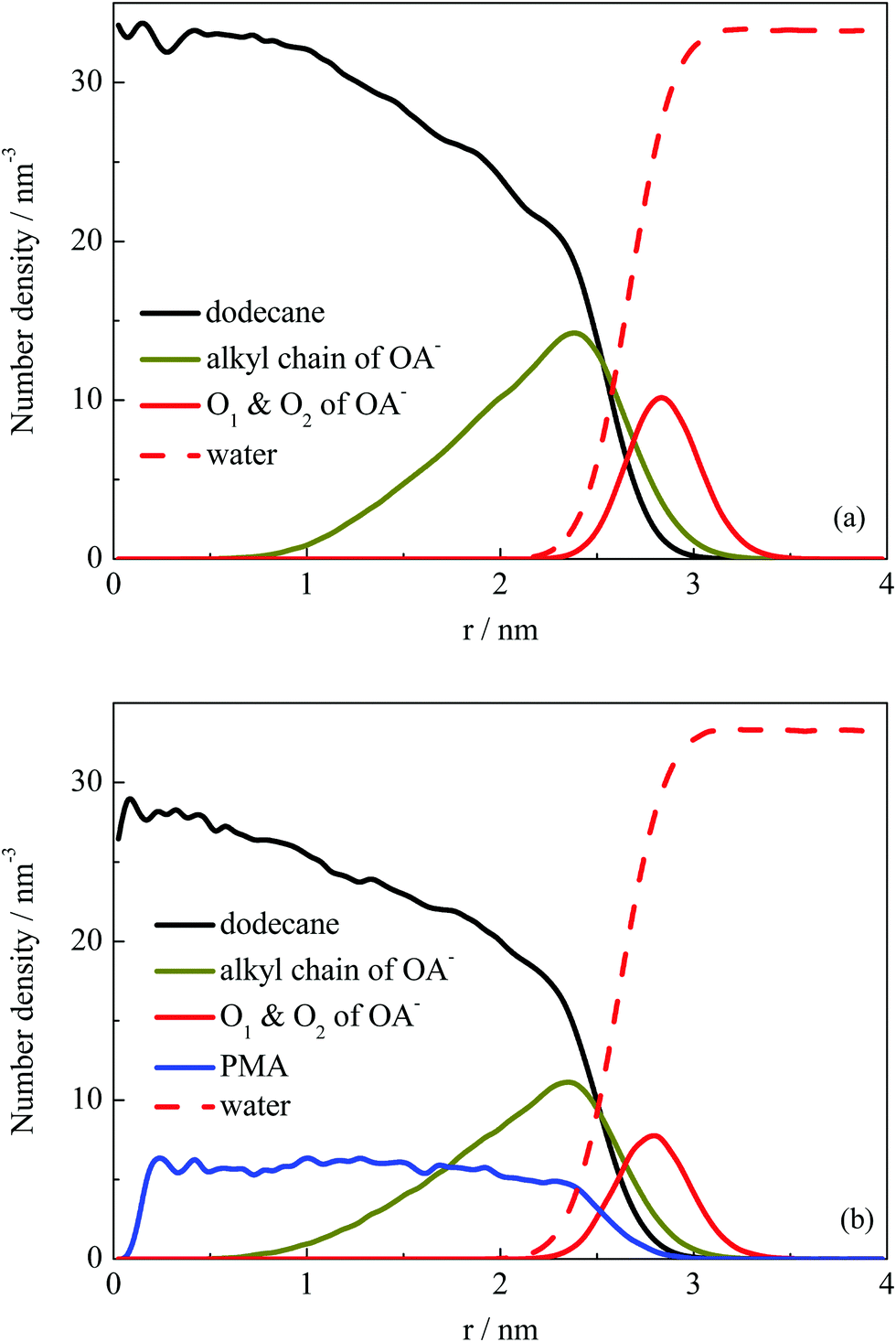 | ||
| Fig. 4 Number density distribution of components with respect to COM of one selected droplet for systems I (a) and II (b). Water molecules were represented by their O atoms, while the densities for hydrocarbon chains and PMA were calculated using all the atoms in molecules. The values of headgroup O1 and O2 atoms were multiplied by 10 for clarity. | ||
Demulsification by PMA2+
The dynamic change of the configurations for system III is shown in Fig. 5a. As mentioned in the Experimental section, the initial setup of this system was identical to those of the first two systems, i.e., these systems were performed from the random distribution of the components. The continuous droplet coalescence during the early stage was also observed. What is different is that all oil and surfactant molecules along with the PMA2+ ions formed one droplet after about 35 ns simulation. The configuration at the end of the simulation (50 ns) shows that the protonated PMA2+ covered on the droplet surface. In addition, it is noted that there was still part of PMA2+ dissolved in the water phase because of their strong affinity for water molecules. | ||
| Fig. 5 (a) Number of the formed clusters in system III plotted with time evolution. (b) Time varying curves of the COM distance between two droplets and the number of adsorbed PMA2+ on the droplet surface (system IV). Several configurations at different times are also shown. PMA2+ molecules are shown in yellow and the other details shown are identical to those shown in Fig. 2. | ||
System IV was performed to check the effect of the initial status on the simulated results. After inserting PMA2+ ions into the water phase of the final configuration obtained from system I, the distance variation between two emulsion droplets was plotted with time evolution, as shown in Fig. 5b. It is noted that the COM distance began to decrease after about 12 ns simulation. During this period, we observed that most of the PMA2+ molecules were gradually adsorbed onto the droplet surface from the water phase. In Fig. 5b, the absolute number of PMA2+ absorbed on the surface of each droplet was counted with time. It is found that the amount of PMA2+ absorbed on each droplet surface reached a stable value after about 12 ns. From then on, the two droplets began to approach each other. At about 15 ns, the two droplets connected and then they gradually fused into one droplet. The simulated results of system V are shown in Fig. S5, ESI.† It is found that after PMA molecules were protonated (i.e., the two terminal N atoms were connected by H atoms), they would migrate to the droplet surface from the inner region. Similarly, after the two droplets were covered by PMA2+, they would soon approach each other and fuse together. The final configurations obtained from systems III–V were precisely the same, suggesting that the initial positions of components have no effect on the simulation results.
The structural properties of the formed droplet were further investigated. Fig. 6a shows the number density distribution profile for a droplet formed at about 10 ns in system III. The density distribution was calculated on the basis of the MD trajectories from 10–30 ns. Comparing the profile shown in Fig. 4, the relative locations of dodecane and OA− molecules did not change. However, the PMA2+ molecules were found to be located at the outermost shell of the droplet. To give a clear view of the PMA2+ locations on the droplet surface, a configuration of the droplet (at 30 ns) is shown in Fig. 6b. It is clear that PMA2+ molecules were associated with the surfactant headgroups through electronic interactions, forming ion pairs. As is well known, surface-charges played an important role in the stabilization of many colloid and emulsion systems. Many computational studies also reported the significant function of electrostatic interactions during various processes of surfactant self-assembly.47–52
 | ||
| Fig. 6 (a) Number density distribution of components with respect to a selected droplet derived from system III. (b) Binding structure of PMA2+ with surfactant headgroups on the droplet surface. The headgroup O atoms of OA− are highlighted to give a clear view. | ||
Besides, we found that the arrangement of OA− surfactants becomes more concentrated on the droplet surface. As a comparison, a configuration of the droplet in the absence of PMA2+ is shown in Fig. S6 (ESI†). It shows that the distribution of OA− surfactants on the surface was much uniform, due to the electrostatic repulsion among the headgroups. While in the presence of PMA2+, almost all the anionic headgroups were binding with the positive PMA2+, as shown in Fig. 6b. Since one PMA2+ may bind with two or more OA− headgroups, these positive ions adsorbed on the droplet surface gathered the negative headgroups, resulting in uneven distribution of ion pairs on the droplet surface. The hydrophilic groups were then distributed concentratedly, leaving large hydrophobic areas exposed to the water phase. In addition, the surfactant headgroups were separated with water by PMA2+ ions, which may reduce the surface activity of the surfactants. Both factors were considered to contribute to the constant coalescing of the droplets, resulting in the final demulsification.
Fusion process between droplets
As discussed above, no matter how many droplets formed finally, droplet coalescence always occurred during the simulation process. To investigate the effect of PMA or PMA2+ on the emulsification or demulsification process, the detailed information about the droplets’ coalescence was explored by observing the simulated trajectories. Fig. S7 in the ESI† shows the coalescence between two droplets selected from the trajectories of system I. We found that for the surfactant-stabilized droplets without any additives, the surfactant headgroups would be mutually exclusive when the two droplets got closer to each other. Until the surfactants on the droplet contact surface were repelled aside and the interior hydrophobic components exposed toward the water phase, the two droplets began to fuse together through the internal oil molecules. This reflects that the hydrophilic headgroup shell on the droplet surface will play a key role in preventing droplets’ coalescence, due to the electrostatic repulsion among the positive headgroups.In the presence of PMA (system II), the droplet coalescence process was very rapid, compare Fig. 2a and b. Especially at the first 10 ns, the first formed small droplets soon fused into three larger droplets. This indicates that it is much easier to obtain a stable emulsion if PMA molecules are present. Fig. 7 shows the instantaneous configurations of two droplets selected from system II. When the two droplets got close enough, we may also observe that the OA− headgroups on the contacting surface were under surface repulsive force. Besides the electrostatic repulsion between carboxyl groups, these hydrophilic headgroups also did not prefer to contact with the outside hydrophobic oil molecules (7.8 ns). What is more important, the PMA molecules which were distributed among surfactant headgroups may bridge two droplets through the interaction with the headgroups (8.2 and 8.4 ns). Before the formation of final stable emulsion droplets, this interaction helps to accelerate the fusion process among the small droplets.
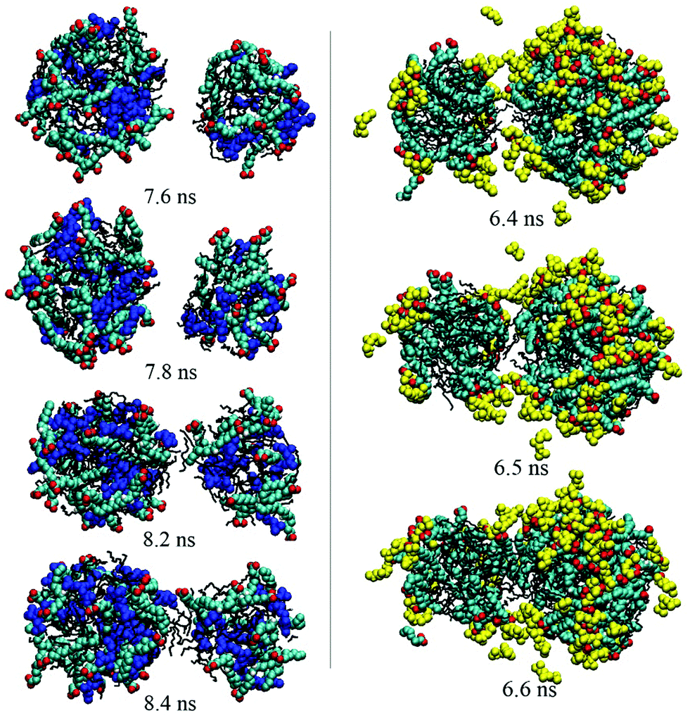 | ||
| Fig. 7 Dynamical process of the droplets’ coalescence. The left and right figures show the configurations derived from systems II and III, respectively. PMA and PMA2+ are shown in blue and yellow, respectively. The other details shown are identical to those shown in Fig. 2. | ||
Fig. 5 shows that two droplets formed in less than 10 ns and they fused into one droplet within 40 ns. Compared with the first two systems, the droplets’ integration got an obvious speed improvement in the presence of PMA2+ ions. Thus, the protonation of PMA molecules was considered to play a key role in breaking the emulsion. To observe the microscopic behavior of PMA2+ in the droplets’ coalescence process, instantaneous configurations of two droplets derived from system III are also shown in Fig. 7. No obvious repulsion interactions were found between the surfactant headgroups when the two droplets got closer. Instead, PMA2+ can bridge surfactant headgroups, which efficiently shielded the electrostatic repulsion between two droplets. Subsequently, the interior oil molecules integrated and linked the two droplets together.
In summary, the effect of PMA2+ embodied in two aspects. On the one hand, PMA2+ ions covered the droplet surface due to electrostatic interactions with surfactant headgroups, reducing the electrostatic repulsion between two droplets. On the other hand, PMA2+ can combine with more than two headgroups, making much concentrated distribution of headgroups on the droplet's surface (Fig. 6b). Thus, more hydrophobic areas were exposed to the water phase, which may facilitate the droplets’ coalescence. As for the effect of HCO3−, Fig. 6a shows that a certain amount of HCO3− ions was distributed on the droplet's surface through electrostatic interactions with PMA2+. During the droplets’ fusion process, HCO3− ions were also distributed around the ion pairs and interacted with PMA2+ through electrostatic interactions, but they did not affect the formation of ion pairs between PMA2+ and OA− (Fig. S8, ESI†).
In the above systems, all the PMA molecules were set to change into PMA2+ after bubbling CO2 for the sake of convenience. To explore the composition on the droplet coalescence, several simulated systems were performed. In these systems, the quantities of oil and surfactant were kept constant, while the ratio between PMA and PMA2+ was varied to mimic the process of gradual gas bubbling. The results are shown in Fig. S9 (ESI†). When the quantity of PMA2+ was less (0 and 10%), two droplets formed within 50 ns without further droplet coalescence. While when the percentage of PMA2+ was above 25%, one droplet formed within 50 ns, suggesting the emulsion was broken. The results show that, when a certain amount of PMA2+ generated with bubbling CO2, the emulsion would be broken into a two-phase water–oil form.
To investigate the repulsion effect between different droplets, the potential of mean force (PMF) for two droplets’ coalescence was calculated using the umbrella sampling method.53 First, the steered molecular dynamics (SMD)54 was performed to obtain a series of configurations for two droplets approaching each other. For the systems with and without PMA, the two droplets were both derived from the final configuration (100 ns) of system II. While for the droplets with PMA2+, the two droplets were derived from the configuration at 10 ns simulation of system IV. In this way, the numbers of components except for the TAs additives are equal in the three cases. An illustration is presented in Fig. S10 in the ESI† to show the initial setup for the SMD simulations. By applying an external force, one droplet was pulled toward the other one. During this process, a harmonic potential with a force constant of 1000 kJ mol−1 nm−2 and a pull rate of 0.001 nm ps−1 was used. A series of sampling windows were generated as a function of distance between the two droplets’ COMs along the z direction. A 5 ns MD simulation was performed for each sampling window. PMF profiles were integrated using the weighted histogram analysis mothed (WHAM).55
The PMF profiles for the fusion process of the three droplets are shown in Fig. 8a. The PMF profiles achieved a satisfactory convergence when the two droplets were separated at a distance above 7 nm, suggesting a 5 ns sampling simulation was sufficient. An energy barrier occurred when two OA−/oil or OA−/PMA/oil droplets got closer, suggesting that repulsion forces existed when these two kinds of droplets were fusing together. Fig. S11 in the ESI† shows the configurations corresponding to the maximum point of the PMF curves. On the droplets’ surface to be touched, it is clear that the headgroups were bent toward the droplet interior, suggesting they were being repulsed. The repulsion resulted in the energy barrier of the PMF, which contributed to the emulsion stability. In the case of PMA2+, when the two droplets got closer, the energy would be soon decreased without any energy barrier appearing. As discussed above, PMA2+ covered the surface of the droplet and made the surfactants more concentrated. Then, the large-area of oil molecules on the surface facilitated the droplets’ integration, resulting in the final separation between the oil and solution.
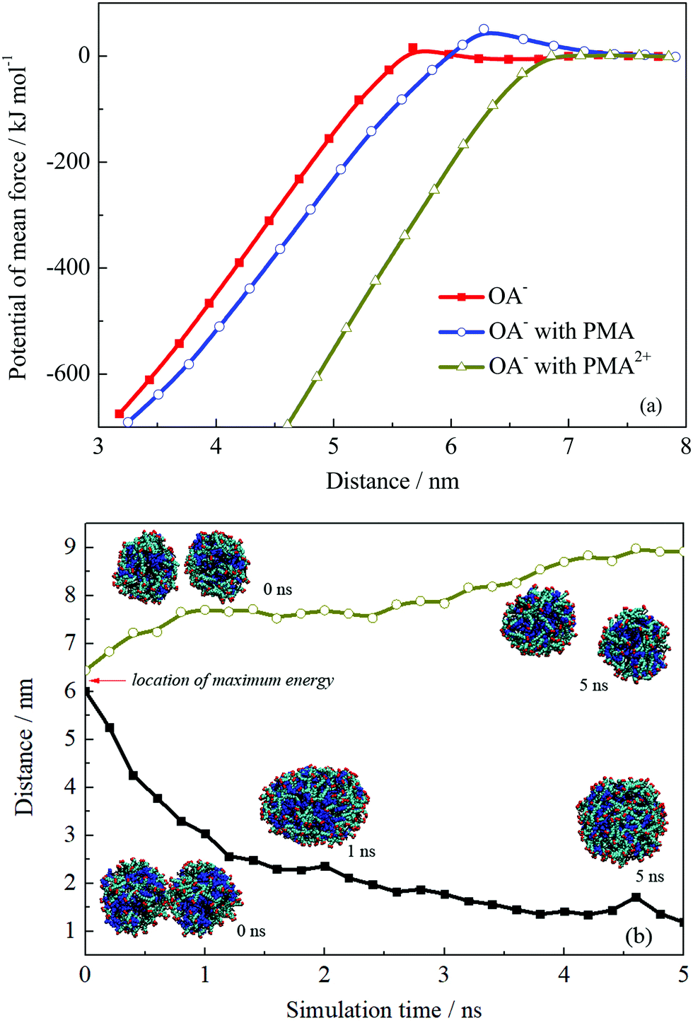 | ||
| Fig. 8 (a) Potential of mean force of two droplets’ coalescence. (b) Distance variations and configurations of two droplets’ coalescence or separation. | ||
The appearance of the energy barrier indicates that the repulsion between two emulsion droplets can prevent the droplets’ coalescence. If the attraction interaction between two droplets cannot overcome the energy barrier, the coalescence would not occur and the stable dispersive emulsion droplets formed. To confirm the point, we performed two more simulations for the droplet formed by OA−/PMA and dodecane. The initial configurations were derived from the pulling simulations and the separation distances between the two droplets were ∼6.0 and 6.5 nm, which were just located at the two sides of the energy barrier. The distance variations between two droplets are shown in Fig. 8b. It shows that the two droplets initially separated at 6.0 nm spontaneously fused into one droplet after 1 ns MD simulation. This is because that the system energy was very high because the two droplets were placed very close under an external force. To reduce the system energy, an effective way for the two droplets was fusing together. Whereas for the two droplets placed at 6.5 nm, further separation can reduce the system energy. In addition, the free energy barrier of the system containing PMA is higher than that without PMA. The maximum values of the energy barrier for the two systems are 51.04 and 15.72 kJ mol−1, respectively. This suggests that the addition of PMA can improve the stability of the emulsion.
Hydration properties of the droplet surface
The emulsion stability should be related to the interfacial activity of surfactants on the droplet surface. To investigate the hydration structural properties of OA− headgroups in each system, the radial distribution functions (RDFs) between carboxyl groups and water O atoms were calculated. Fig. 9 shows the RDF profiles with a cutoff at 1 nm to give a clear view of water shells around the surfactant headgroups. In the emulsion system, two well-organized hydration shells were found around the OA− carboxyl groups, indicating strong headgroup–water interactions. It is worth mentioning that the intensities of the first two peaks were all slightly strengthened in the presence of PMA molecules. This is mainly because that PMA molecules were solubilized into the droplets and distributed around the surfactant headgroups. Thus, the packing of the surfactant headgroups on the droplet surface was considered to be much looser than without PMA molecules. The packing of the surfactant headgroups on the droplet surface of these three systems was compared by the corresponding headgroup O–O RDFs, as shown in Fig. S12, ESI.† The intensity of the RDF peaks for the system with PMA2+ is the strongest, because the headgroups were concentrated through the strong electrostatic binding with PMA2+ as discussed above. In the presence of PMA, the intensity of the RDF peaks was slightly lower than that without any additives. This confirmed that the solubilized PMA can screen the repulsion between the OA− headgroups.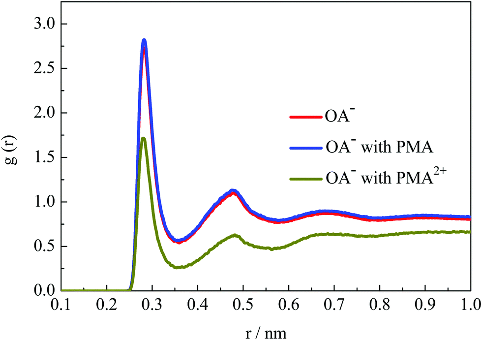 | ||
| Fig. 9 RDFs of water molecules around headgroup oxygen atoms. | ||
PMA2+ can cover the droplet surface, resulting in the reduction of surfactant headgroups’ hydration capacity. And then, the stability of the emulsion droplets will be destroyed. However, it should be noted that the PMA2+ salts were also water soluble. To further investigate the hydration behavior of the droplet formed by PMA2+ and surfactants, the RDFs of water molecules around PMA2+ were calculated (Fig. S12, ESI†). Although there was an evident hydration shell around the terminal tertiary amine groups, especially around the connected H atoms at about 0.2 nm, the peak strength was very weak. Thus, the hydrophilic ability of the droplet surface in the presence of PMA2+ can be ignored.
Above all, PMA2+ combined with the surfactant headgroups on the droplet surface, making the surfactant distribute more concentrated. Moreover, the surface activity was significantly reduced. These two factors make the droplets similar to hydrophobic oil droplets. Therefore, these droplets will quickly fuse together leading to demulsification. Although it is hard to observe the precipitation phenomenon for simulations, we can still find the ion pairs formed between PMA2+ and OA−. Moreover, by analyzing the hydration character of the droplet surface, it can be confirmed that the combination between PMA2+ and OA− ultimately resulted in demulsification.
Conclusions
The emulsification/demulsification processes controlled by a switchable surfactant/additive system were investigated using molecular dynamics simulations. The simulated results showed that both NaOA and NaOA/PMA systems can be used to stabilise dodecane/water emulsions. The surfactant NaOA molecules were distributed on the droplets’ surface, with their hydrocarbon chains inserted into the oil phase. The polar headgroups on the droplets’ surface should contribute to the electrostatic repulsion among the emulsion droplets. In the presence of PMA, the simulation time is shorter for the formation of two emulsion droplets, suggesting that the added PMA molecules helped to stabilize the emulsion.When PMA molecules were converted into their protonated form, PMA2+ combined with surfactant headgroups on the droplets’ surface. Besides, the surfactants were much concentrated and the hydrophilicity of the headgroups decreased significantly. The calculated PMF of emulsion droplets’ coalescence showed energy barriers, suggesting that the repulsion among the headgroups played a key role in stabilizing the emulsion. The ion pairs formed between PMA2+ and surfactants reduced the repulsion interactions among droplets, resulting in droplets’ coalescence and demulsification. Our simulated models succeeded in reproducing the experimental observations and provided insights into the CO2-responsiveness of the surfactant/TA system. On the basis of this work, the structure factors of TAs, such as the number of tertiary amine groups and the position of hydroxyl groups, which would affect the CO2-responsive performance, are expected to be further studied.
Conflicts of interest
There are no conflicts to declare.Acknowledgements
This work was financially supported by the National Natural Science Foundation of China (21203084) and Project of Shandong Province Higher Educational Science and Technology Program (J18KA075).References
- Y. Liu, P. G. Jessop, M. Cunningham, C. A. Eckert and C. L. Liotta, Science, 2006, 313, 958–960 CrossRef CAS.
- P. Brown, C. P. Butts and J. Eastoe, Soft Matter, 2013, 9, 2365–2374 RSC.
- P. G. Jessop, S. M. Mercer and D. J. Heldebrant, Energy Environ. Sci., 2012, 5, 7240–7253 RSC.
- J. Eastoe and A. Vesperinas, Soft Matter, 2005, 1, 338–347 RSC.
- K. Tsuchiya, Y. Orihara, Y. Kondo, N. Yoshino, T. Ohkubo, H. Sakai and M. Abe, J. Am. Chem. Soc., 2004, 126, 12282–12283 CrossRef CAS.
- S. M. Mercer, T. Robert, D. V. Dixon, C.-S. Chen, Z. Ghoshouni, J. R. Harjani, S. Jahangiri, G. H. Peslherbe and P. G. Jessop, Green Chem., 2012, 14, 832–839 RSC.
- Y. Zhang, Y. Feng, J. Wang, S. He, Z. Guo, Z. Chu and C. A. Dreiss, Chem. Commun., 2013, 49, 4902–4904 RSC.
- C. D. Umeasiegbu, V. Balakotaiah and R. Krishnamoorti, Langmuir, 2016, 32, 655–663 CrossRef CAS.
- R. G. Shrestha, L. K. Shrestha and K. Aramaki, J. Colloid Interface Sci., 2007, 311, 276–284 CrossRef CAS.
- P. Xu, Z. Wang, Z. Xu, J. Hao and D. Sun, J. Colloid Interface Sci., 2016, 480, 198–204 CrossRef CAS.
- M. Zhao, M. Gao, C. Dai, C. Zou, Z. Yang, X. Wu, Y. Liu, Y. Wu, S. Fang and W. Lv, Langmuir, 2017, 33, 4319–4327 CrossRef CAS.
- A. F. Dexter, A. S. Malcolm and A. P. J. Middelberg, Nat. Mater., 2006, 5, 502–506 CrossRef CAS.
- C. B. Minkenberg, L. Florusse, R. Eelkema, G. J. M. Koper and J. H. van Esch, J. Am. Chem. Soc., 2009, 131, 11274–11275 CrossRef CAS.
- Z. Chu and Y. Feng, Chem. Commun., 2011, 47, 7191–7193 RSC.
- X. Wei, A. Ping, P. Du, J. Liu, D. Sun, Q. Zhang, H. Hao and H. Yu, Soft Matter, 2013, 9, 8454–8463 RSC.
- H. Sakai, A. Matsumura, S. Yokoyama, T. Saji and M. Abe, J. Phys. Chem. B, 1999, 103, 10737–10740 CrossRef CAS.
- S. S. Datwani, V. N. Truskett, C. A. Rosslee, N. L. Abbott and K. J. Stebe, Langmuir, 2003, 19, 8292–8301 CrossRef CAS.
- S. Dai, P. Zhu, Y. Suo and H. Lu, J. Phys. Chem. B, 2019, 123, 2558–2566 CrossRef CAS.
- S. Dai, Y. Suo, D. Liu, P. Zhu, J. Zhao, J. Tan and H. Lu, Phys. Chem. Chem. Phys., 2018, 20, 11285–11295 RSC.
- C. Liang, J. R. Harjani, T. Robert, E. Rogel, D. Kuehne, C. Ovalles, V. Sampath and P. G. Jessop, Energy Fuels, 2011, 26, 488–494 CrossRef.
- C. I. Fowler, P. G. Jessop and M. F. Cunningham, Macromolecules, 2012, 45, 2955–2962 CrossRef CAS.
- L. M. Scott, T. Robert, J. R. Harjani and P. G. Jessop, RSC Adv., 2012, 2, 4925–4931 RSC.
- C. I. Fowler, C. M. Muchemu, R. E. Miller, L. Phan, C. O’Neill, P. G. Jessop and M. F. Cunningham, Macromolecules, 2011, 44, 2501–2509 CrossRef CAS.
- E. Ceschia, J. R. Harjani, C. Liang, Z. Ghoshouni, T. Andrea, R. S. Brown and P. G. Jessop, RSC Adv., 2014, 4, 4638–4645 RSC.
- R. Nistico, L. R. Celi, A. Prevot, L. Carlos, G. Magnacca, E. Zanzo and M. Martin, J. Hazard. Mater., 2018, 342, 260–269 CrossRef CAS.
- J. Liu, Y. Zhao and S. Ren, Energy Fuels, 2015, 29, 1233–1242 CrossRef CAS.
- D. C. Steytler, E. Rumsey, M. Thorpe, J. Eastoe, A. Paul and R. K. Heenan, Langmuir, 2001, 17, 7948–7950 CrossRef CAS.
- X. Liu, Y. Li, S. Tian and H. Yan, J. Phys. Chem. C, 2019, 123, 25246–25254 CrossRef CAS.
- S. Salaniwal, S. T. Cui, H. D. Cochran and P. T. Cummings, Langmuir, 2001, 17, 1784–1792 CrossRef CAS.
- F. Goodarzi and S. Zendehboudi, Can. J. Chem. Eng., 2019, 97, 281–309 CrossRef CAS.
- F. Goodarzi, J. Kondori, N. Rezaei and S. Zendehboudi, J. Mol. Liq., 2019, 295, 111357 CrossRef CAS.
- H. Dominguez and M. L. Berkowitz, J. Phys. Chem. B, 2000, 104, 5302–5308 CrossRef CAS.
- F. Goodarzi and S. Zendehboudi, Ind. Eng. Chem. Res., 2019, 58, 8817–8834 CAS.
- S. Aland and A. Voigt, Colloids Surf., A, 2012, 413, 298–302 CrossRef CAS.
- M. J. Abraham, T. Murtola, R. Schulz, S. Páll, J. C. Smith, B. Hess and E. Lindahl, SoftwareX, 2015, 1, 19–25 CrossRef.
- S. Páll, M. J. Abraham, C. Kutzner, B. Hess and E. Lindahl, Solving Software Challenges for Exascale, 2015, vol. 8759, pp. 3–27 Search PubMed.
- S. Pronk, S. Páll, R. Schulz, P. Larsson, P. Bjelkmar, R. Apostolov, M. R. Shirts, J. C. Smith, P. M. Kasson, D. van der Spoel, B. Hess and E. Lindahl, Bioinformatics, 2013, 29, 845–854 CrossRef CAS.
- B. Hess, C. Kutzner, D. van der Spoel and E. Lindahl, J. Chem. Theory Comput., 2008, 4, 435–447 CrossRef CAS.
- W. Huang, Z. Lin and W. F. van Gunsteren, J. Chem. Theory Comput., 2011, 7, 1237–1243 CrossRef CAS.
- A. K. Malde, L. Zuo, M. Breeze, M. Stroet, D. Poger, P. C. Nair, C. Oostenbrink and A. E. Mark, J. Chem. Theory Comput., 2011, 7, 4026–4037 CrossRef CAS.
- H. J. C. Berendsen, J. R. Grigera and T. P. Straatsma, J. Phys. Chem., 1987, 91, 6269–6271 CrossRef CAS.
- G. Bussi, D. Donadio and M. Parrinello, J. Chem. Phys., 2007, 126, 014101 CrossRef.
- H. J. C. Berendsen, J. P. M. Postma, W. F. van Gunsteren, A. DiNola and J. R. Haak, J. Chem. Phys., 1984, 81, 3684–3690 CrossRef CAS.
- B. Hess, H. Bekker, H. J. C. Berendsen and J. G. E. M. Fraaije, J. Comput. Chem., 1997, 18, 1463–1472 CrossRef CAS.
- U. Essman, L. Perera, M. L. Berkowitz, T. Darden, H. Lee and L. G. Pedersen, J. Chem. Phys., 1995, 103, 8577–8593 CrossRef.
- W. Humphrey, A. Dalke and K. Schulten, J. Mol. Graphics, 1996, 14, 33–38 CrossRef CAS.
- M. S. Bodnarchuk, D. Dini and D. M. Heyes, Langmuir, 2017, 33, 7263–7270 CrossRef CAS.
- A. Date, R. Ishizuka and N. Matubayasi, Phys. Chem. Chem. Phys., 2016, 18, 13223–13231 RSC.
- A. Ramazani, T. Mandal and R. G. Larson, Langmuir, 2016, 32, 13084–13094 CrossRef CAS.
- Z. Liu, P. Wang, S. Pei, B. Liu, X. Sun and J. Zhang, Colloids Surf., A, 2016, 506, 276–283 CrossRef CAS.
- J. F. Chen and J. C. Hao, Phys. Chem. Chem. Phys., 2013, 15, 5563–5571 RSC.
- H. Yan, Z. Han, K. Li, G. Li and X. Wei, Langmuir, 2018, 34, 351–358 CrossRef CAS.
- G. M. Torrie and J. P. Valleau, J. Comput. Phys., 1977, 23, 187–199 CrossRef.
- S. Izrailec, S. Stepaniants, B. Isralewitz, D. Kosztin, H. Lu, F. Molnar, W. Wriggers and K. Schulten, Steered Molecular Dynamics, Springer-Verlag, Berlin, Germany, 1998 Search PubMed.
- S. Kumar, J. M. Rosenberg, D. Bouzida, R. H. Swendsen and P. A. Kollman, J. Comput. Chem., 1992, 13, 1011–1021 CrossRef CAS.
Footnote |
| † Electronic supplementary information (ESI) available: Summary of the simulated systems; the simulated results of the additional systems; the detailed structure of a droplet formed by OA−/PMA/oil; droplets’ coalescence in system I; the configuration of HCO3− on the droplet; the results of the systems with different ratios of PMA/PMA2+; an illustration for the SMD simulations; configurations corresponding to the maximum point of PMF; and RDFs of water around the headgroup or PMA2+. See DOI: 10.1039/d0cp05686c |
| This journal is © the Owner Societies 2021 |