
 Open Access Article
 This Open Access Article is licensed under a Creative Commons Attribution-Non Commercial 3.0 Unported Licence
3D printed MOF-based mixed matrix thin-film composite membranes†
Sameh K. Elsaidi *ab,
Mayur Ostwalcd,
Lingxiang Zhuae,
Ali Sekizkardesae,
Mona H. Mohamedfg,
Michael Gippleah,
Jeffrey R. McCutcheon*cd and
David Hopkinsona
*ab,
Mayur Ostwalcd,
Lingxiang Zhuae,
Ali Sekizkardesae,
Mona H. Mohamedfg,
Michael Gippleah,
Jeffrey R. McCutcheon*cd and
David Hopkinsona
aDOE National Energy Technology Laboratory (NETL), Pittsburgh, PA 15236, USA. E-mail: samehelsaidi@mail.usf.edu
bOak Ridge Institute for Science and Education, Pittsburgh, PA 15236, USA
cConnecticut Center for Applied Separations Technology, University of Connecticut, Storrs, CT, USA. E-mail: jeffrey.mccutcheon@uconn.edu
dDepartment of Chemical & Biomolecular Engineering, Center for Environmental Sciences and Engineering, University of Connecticut, Storrs, CT, USA
eLeidos Research Support Team, 626 Cochrans Mill Road, P.O. Box 10940, Pittsburgh, PA 15236, USA
fChemistry Department, Faculty of Science, Alexandria University, P.O. Box 426, Ibrahimia, Alexandria, 21321, Egypt
gDepartment of Chemistry, University of Pittsburgh, 219 Parkman Avenue, Pittsburgh, PA, USA
hDeltha, New Orleans, LA 70114, USA
First published on 26th July 2021
Abstract
MOF-based mixed-matrix membranes (MMMs) have attracted considerable attention due to their tremendous separation performance and facile processability. In large-scale applications such as CO2 separation from flue gas, it is necessary to have high gas permeance, which can be achieved using thin membranes. However, there are only a handful of MOF MMMs that are fabricated in the form of thin-film composite (TFC) membranes. We propose herein the fabrication of robust thin-film composite mixed-matrix membranes (TFC MMMs) using a three dimensional (3D) printing technique with a thickness of 2–3 μm. We systematically studied the effect of casting concentration and number of electrospray cycles on membrane thickness and CO2 separation performance. Using a low concentration of polymer of intrinsic microporosity (PIM-1) or PIM-1/HKUST-1 solution (0.1 wt%) leads to TFC membranes with a thickness of less than 500 nm, but the fabricated membranes showed poor CO2/N2 selectivity, which could be attributed to microscopic defects. To avoid these microscale defects, we increased the concentration of the casting solution to 0.5 wt% resulting in TFC MMMs with a thickness of 2–3 μm which showed three times higher CO2 permeance than the neat PIM-1 membrane. These membranes represent the first examples of 3D printed TFC MMMs using the electrospray printing technique.
1. Introduction
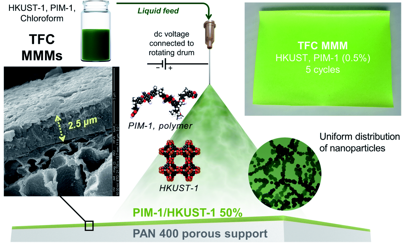
Mixed-matrix membranes (MMMs) have emerged as a promising technology for gas separation applications.1–7 They combine the advantages of polymeric membranes, including robustness and ease of fabrication, and the inorganic materials for their superb separation performance. This improved performance can be more pronounced if thin-film composite (TFC) membranes are used because membrane thinning can allow for high gas flux and gas permeation without compromising selectivity.8–10 Metal–organic frameworks (MOFs) have gained significant attention as filler particles in MMMs due to their high degree of modularity, permanent porosity, tunable pore size, and multifarious functionalities.11–18 However, it is a challenge to fabricate continuous and defect-free TFC MMMs. TFC membranes can be fabricated via various approaches, such as interfacial polymerization, dip coating, spin coating, slot-die coating, knife coating, and bar coating.19–21 However, these methods have some challenges that are not suitable for MOFs, such as using aggressive chemicals, complexity and limitations in processing.22–25 Three-dimension (3D) printing or additive manufacture (AM) has found its applications in various areas, such as medicine, constructions, art, automotive, aerospace, and engineering.26,27 However, the use of 3D printing for the fabrication of the separation membranes is relatively new.28 3D printing techniques could provide more control towards the design, shape, thickness, and roughness of the separation membrane, which cannot be achieved using conventional fabrication techniques.28,29 Besides, 3D membrane printing can deliver numerous benefits that are highly desirable for the manufacturing, commercialization, and practicality of MMMs, such as speed, cost, precision, consistency, and quality. Recent research has shown a tremendous capacity for 3D printing to control membrane smoothness and thickness, exemplified by the 3D printed polyamide membrane reaching a thickness as low as 15 nm.30On the other hand, 3D printing of mixed-matrix membranes (MMMs) is generally unexplored. A recent report demonstrated the fabrication of mixed-matrix films (MMFs) using the 3D printing technique. The MMFs are fabricated as a single layer with different grid patterns using selective laser sintering for water purification applications.31 As a part of our efforts to control and improve the MMM fabrication, we developed the first examples of 3D printed TFC MMMs consisting of HKUST-1 as filler and PIM-1 matrix using the electrospray printing technique. This could be a breakthrough for MOF-based MMM scale-up and commercialization, which can only be realized using nanoscale MOFs to produce thin selective layers.
Fenn et al. used the electrospray printing technique for mass spectrometry of large polar biomolecules.32 Others used the same technique to make thin films, nanoparticles, or patterns.32–36 We recently used the same approach to deposit individual monomers onto a substrate, subsequently polymerizing on the surface to create membranes for reverse osmosis.30
2. Experimental
2.1 Synthesis
HKUST-1 synthesis was performed using a direct mixing procedure using acetic acid as modulator. A 100 ml ethanolic solution of 1 mmol trimesic acid was mixed directly with a 100 ml solution of 2 mmol copper acetate dissolved in 90 ml water and 10 ml of acetic acid. An immediate sky blue color of HKUST-1 nanoparticles was formed and the suspended powder was centrifuged immediately to avoid crystal growth. HKUST-1 nanoparticles were thoroughly solvent-exchanged with ethanol, acetone then methanol to remove unreacted starting materials and acetic acid.
2.1.3.1 Preparation of 2 wt% PIM-1 solution. A 2 g of PIM-1 was added to 98 g of chloroform. The solution was then sonicated until the polymer is completely soluble.
2.1.3.2 Preparation of 2 wt% PIM-1/HKUST-1 solution. In a glove box, 300 mg of activated MOF nanoparticles is added to the 1.7 g of PIM-1 in 98 g of chloroform and sonicated for several hours until all the MOF particles get suspended.
The 0.1 wt% and 0.5 wt% solutions of PIM-1 and PIM-1/HKUST-1 were prepared by dilution of the 2 wt% solutions with chloroform.
2.1.3.3 Membrane fabrication (electrospray deposition of PIM-1/HKUST-1). The membranes were fabricated following the 3D printing (electrospray) procedure reported in literature.30 The schematic for the electrospray system utilized is shown in Fig. S1.† A stainless-steel needle was connected to a high voltage DC power source (Gamma High Voltage Research, Ormond Beach, FL) which can generate up to 30 kV. A 12′′ diameter rotating drum was grounded to generate potential difference between the drum and the needle tip. The needle was suspended from an L-shaped arm attached to a stage. ∼5 cm distance was kept between the needle tip and the rotating drum. The stage was mounted on a screw slider moves horizontally (across the length of the rotating drum) using a stepper motor that is controlled by a motor controller (Velmex, Bloomfield, NY).
To print the membrane on the support, the drum is fist covered with a Aluminum foil and the PAN 400 support (∼3′′ × 6′′) was then attached and wrapped around the foil-wrapped drum using tape. Part of the aluminum foil on the edges was left exposed. PIM-1 and HKUST-1 solution (0.1 or 0.5 wt%) was then fed to the needle using a syringe pump at a flowrate of 20 ml h−1 using flexible tubing. Electrospraying was initiated on the exposed (not covered with PAN 400 support) aluminum foil to allow the spray to stabilize. Stable spray refers to a cone-jet mode where the liquid is elongated into a long, fine jet of droplets which deposit onto the substrate surface. The applied voltage was around 6.8 kV. Once the spray was stabilized, the Velmex controller was activated which was programmed to begin the movement of the needle stage over 12 cm horizontally as the drum turned (at 15 rpm). As the drum rotates, the PIM-1 and HKUST-1 solution gets deposited on the PAN support. When the needle traverses the entire PAN 400 support once, that was considered “one scan” or “one cycle”. For multiple scans, the stage would come back to the original position at a speed of 5 cm s−1 and start the next scan. The number of scans were varied from 2–5. After the desired number of scans was done, the sample was removed, and the delivery line was cleaned with chloroform and dried with air.
3. Characterization
3.1 Powder X-ray diffraction
XRD pattern for the crystalline powder of MOF nanoparticles were recorded on a Panalytical X'Pert Pro MPD X-ray Diffractometer using Cu Kα radiation (λ = 1.54 Å at 45 kV and 40 mA) at room temperature. Diffraction data were collected at a scan speed of 0.1° min−1, step size of 0.03° and a 2θ range of 5–40°.3.2 Ultraviolet-visible spectroscopy (UV-VIS)
The UV-VIS of the MOF/polymer dispersed solutions in chloroform were collected on an Agilent 8453 UV-VIS spectrometer.3.3 Gas sorption measurements
Adsorption measurements were conducted on the crystalline powder of HKUST-1 using a Micromeritics 3Flex surface area and gas analyzer instrument within the P/Po range of 0–1.0.3.4 Scanning electron microscope (SEM)
SEM measurements were performed to determine the quality of the fabricated membranes. The samples were prepared by fracturing the membranes in liquid nitrogen and subsequent sputter coating of palladium using a SPI Module Sputter Coater. SEM images were collected using a FEI Company Quanta 600 field-emission scanning electron microscope. SEM was used with a beam energy of 10 kV and a working distance of ∼10 mm in secondary electron mode to examine the morphology of the membranes.3.5 Gas permeation measurements
Pure-gas permeances of TFC membranes were measured in a customized constant-pressure variable volume system. The membrane sample was first masked by a 50 μm thick copper shim using epoxy to seal the rim of the mask before being sealed inside a stainless-steel permeation membrane cell. The active membrane area for gas permeation was about 1 cm2. Pure CO2 or N2 was introduced to the upstream side of the membrane at 1 barg while keeping the permeate side at atmospheric pressure. The trans-membrane steady-state flux was measured using a soap bubble flow meter (<0.1 cm3 min−1) and a digital mass flow meter (0.1–20 cm3 min−1) at the room temperature of 22 °C. To exclude the interference of physical aging effect, all the membrane samples were pretreated with 24 h methanol soaking, followed by a vacuum drying at 40 °C for 3 hours prior to the measurement.4. Results and discussion
The choice of the HKUST-1 as a filler and PIM-1 as a matrix was based on our previous study,39 which revealed their chemical compatibility and their separation performance. The free nitrile functional groups in the PIM-1 backbone can strongly interact with the unsaturated Cu metal centers of HKUST-1. This chemical interaction is important for optimizing the MOF-polymer interfacial compatibility. Fig. S2† shows the ultraviolet-visible spectroscopy (UV-VIS) of a PIM-1/HKUST-1 nanoparticles solution in chloroform. A peak shift to higher energy was observed from 700 nm in HKUST-1 to 580 nm in the PIM-1/HKUST-1 mixture. This could indicate the variation in the Cu electronic environment in HKUST-1 upon the interaction with cyano groups from PIM-1 backbone.X-ray photoelectron spectroscopy (XPS) was used as an evidence for the HKUST-1/PIM-1 interaction.39 The XPS N1s spectra of PIM-1 revealed two equally intense components to the N1s spectrum at 397.7 eV and 399.7 eV from the C![[triple bond, length as m-dash]](https://www.rsc.org/images/entities/char_e002.gif) N functionality of PIM-1. Upon mixing HKUST-1 with PIM-1, the unsaturated Cu centers on the surface of the HKUST-1 can coordinate with the CN of PIM-1 resulted in a shift of the 399.7 eV component of the N1s spectrum to 397.7 eV and an increase in the relative intensity of the other component.39
N functionality of PIM-1. Upon mixing HKUST-1 with PIM-1, the unsaturated Cu centers on the surface of the HKUST-1 can coordinate with the CN of PIM-1 resulted in a shift of the 399.7 eV component of the N1s spectrum to 397.7 eV and an increase in the relative intensity of the other component.39
The formation of small MOF nanoparticles is highly desirable for the uniform distribution of polymer/MOF solution on the substrate. Therefore, we were able to synthesize HKUST-1 nanoparticles in small sizes of ∼30–50 nm (Fig. S3†), as revealed by scanning electron microscopy (SEM). The powder X-ray diffraction (PXRD) showed the high crystallinity of the HKUST-1 nanoparticles (Fig. S4†), and the N2 adsorption isotherm at 77 K revealed the retention of high porosity (BET surface area = 1869 m2 g−1, Fig. S5†).
PIM-1/HKUST-1 mixture was deposited as nanoscale droplets using the electrospray technique forming TFC MMMs on a substrate surface. The electrospray system schematic (Fig. 1 and S1†) and detailed printing procedure are described in the ESI.† In this technique, the liquid containing the MOF/polymer mixture (PIM-1 and HKUST-1 in chloroform) is extruded from the needle in the presence of a strong electric field. This field forces the ejected droplets to spread well with diameters below 1 μm (Fig. 1).
 | ||
| Fig. 1 Schematic demonstration of the electrospray 3D printing approach. | ||
The solution droplet emerging from the needle is then sprayed and deposited on the substrate. The needle moves horizontally over and across the substrate attached on a rotating drum to form a uniform coating. The drum is grounded and connected to the needle through a high-voltage dc power supply that can produce up to 30 kV. A polyacrylonitrile (PAN) microporous membrane was used as a porous substrate due to its superior chemical stability among the commercial microporous membranes. The needle stage passes along the collector surface to ensure coverage of the entire substrate. A single sweep over the surface is denoted as a single scan or cycle. The number of scans or cycles then controlled the thickness of the selective layer.
PXRD confirmed that the MOF structures retained their crystallinity after the membrane fabrication (Fig. S6 in ESI†). The peaks of the PAN support were observed in both the PIM-1 and PIM-1/HKUST-1 TFCs. The SEM revealed the successful fabrication of the TFC membranes (Fig. 2). The membrane thickness of the neat polymer or the TFC MMM-1 using a low concentration (0.1 wt%) of PIM-1 or PIM-1/HKUST-1 was around 400–500 nm. In comparison, the higher concentration solution (0.5 wt%) led to thicker PIM-1 and TFC MMM-2 selective layers with a thickness of 2.5–3 μm. As shown in Fig. S7 in ESI,† PIM-1 TFC prepared by low concentration of PIM-1 (0.1 wt%) showed microscopic defects that are shown only in the surface of the membrane. Therefore, we decided to increase the concentration of the casting solution (PIM-1 and PIM-1/HKUST-1) from 0.1 wt% to 0.5 wt%. SEM cross-sectional and surface images of the fabricated TFC membranes at high concentration of 0.5 wt% did not reveal any noticeable defects (Fig. S8–S11†). The energy-dispersive X-ray spectroscopy (EDX) revealed that MOF nanoparticles (Cu in HKUST-1) were distributed uniformly throughout the membrane cross-section with no visible defects or large-scale phase separation (Fig. 2d).
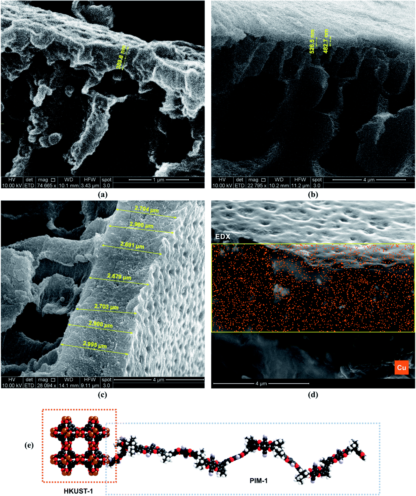 | ||
| Fig. 2 SEM images of the fabricated TFC membranes (5 cycles). (a) 0.1 wt% PIM-1, (b) 0.1 wt% PIM-1/HKUST-1, (c) 0.5 wt% PIM-1/HKUST-1, (d) EDX analysis of 0.5 wt% PIM-1/HKUST-1, and (e) representation of the chemical interaction between the open metal site of the HKUST-1 and the cyano group of PIM-1. The scale bar is shown below each image. The thickness of the membrane is measured in yellow. | ||
As a proof-of-concept demonstration for gas separation applications, we tested these membranes for CO2 separation from flue gas. The gas permeation data revealed that the membranes prepared using a low concentration PIM-1 or PIM-1/HKUST-1 mixture (0.1 wt%) with the membrane thickness below 500 nm showed poor CO2/N2 selectivity, which might be attributed to small defects or imperfections in the fabricated membranes.
After increasing the concentration of the PIM-1 to 0.5 wt%, the membrane selectivity of the neat polymer is dramatically enhanced from 2.6 to 12 for 5 coating cycles. The same behavior was observed in the TFC MMMs by increasing the PIM-1/HKUST-1 concentration to 0.5 wt% and membrane thickness to 2–3 μm, the CO2/N2 selectivity is increased from 2 to 6.4 (Tables 1 and S1;† Fig. 3). Although the CO2/N2 selectivity of the HKUST-1/PIM-1 TFC MMM is decreased compared to the neat polymer, the TFC MMM B#2 showed four times higher CO2 permeance than the neat PIM-1 B#1 membrane. This is a typical trade-off when highly porous filler particles are added to a polymer matrix.
| Membrane | Thickness (μm) | wt% | CO2 permeance (GPU) | CO2/N2 selectivity |
|---|---|---|---|---|
| PIM-1 (LC) | 0.39 | 0.1 | 147 | 2.6 |
| TFC MMM-1 | 0.5 | 0.1 | 305 | 2 |
| PIM-1 (HC) | 2.75 | 0.5 | 159 | 12 |
| TFC MMM-2 | 2.75 | 0.5 | 696 | 6.4 |
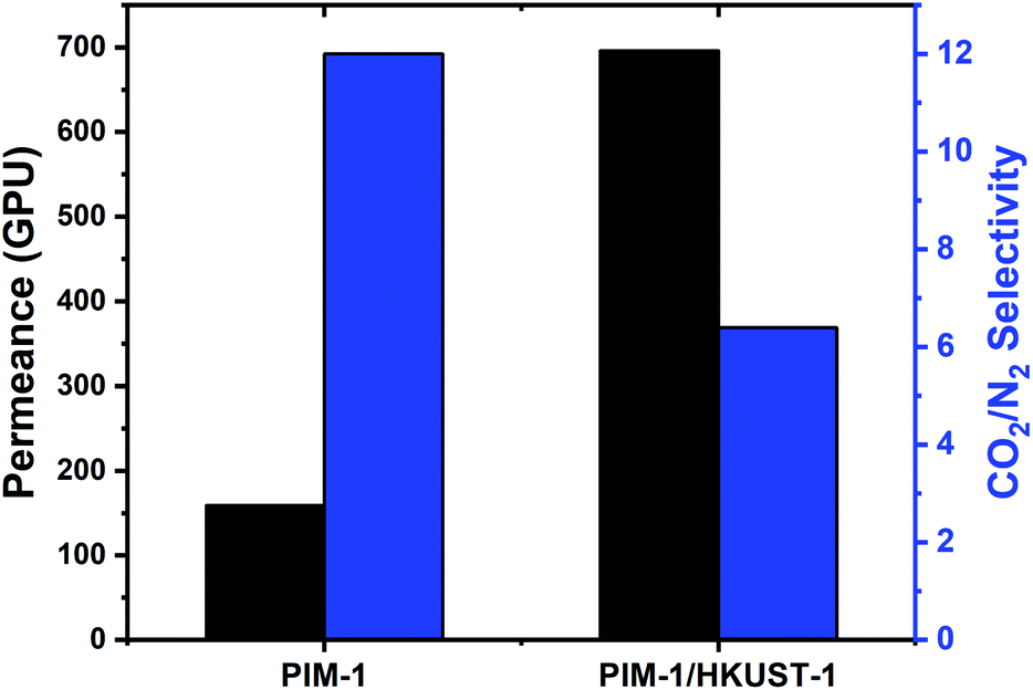 | ||
| Fig. 3 The gas transport properties of the PIM-1/HKUST-1 TFC MMM compared to neat PIM-1 TFC membrane. The CO2 permeance in GPU (gray) and CO2/N2 selectivity (blue). | ||
We also examined the impact of the number of coverage cycles on membrane performance. Using a high concentration of PIM-1, the TFC membrane fabricated using two coverage cycles (PIM-1 B#1) showed comparable permeability and selectivity to the one with five cycles (PIM-1 B#2), which indicates a full coverage of the substrate and formation of membranes without significant defects in both cases. Also, as would be expected, the membrane permeance scales with inverse proportion to selective layer thickness, with more cycles leading to greater thickness.
5. Conclusions
In summary, we successfully fabricated MOF-based TFC-MMMs by incorporating HKUST-1 nanoparticles into a PIM-1 matrix via the 3D electrospray printing technique. The membrane thickness was reduced to maximize the gas permeance while still ensuring that the fabricated membranes are defect-free and sufficiently robust. The thinner membranes (<500 nm) showed a much lower CO2/N2 selectivity, which might be attributed to microscopic defects. However, by increasing the concentration of the membrane compositions to 0.5 wt%, we fabricate 2–3 μm continuous TFC membranes thanks to the high control of the electrospray 3D printing technique. The 2–3 μm thick TFC membranes showed a drastic improvement in CO2/N2 selectivity compared to the thinner membranes. Although TFC MMMs had reduced CO2/N2 selectivity, the MMM showed much higher CO2 permeance than the neat polymer.Conflicts of interest
There are no conflicts to declare.Acknowledgements
This technical report was performed in support of the National Energy Technology Laboratory's ongoing research in CO2 capture under the Carbon Capture field work proposal. This project was funded by the U.S. Department of Energy, National Energy Technology Laboratory, an agency of the United States Government, in part through a support contract with Leidos. Funding was also provided through the Connecticut Center for Applied Separations Technology which is supported by the Connecticut Department of Economic and Community Development. Additional funding and support came from NSF CMMI #2001624. Neither the United States Government nor any agency thereof, nor any of their employees, nor Leidos, nor any of their employees, makes any warranty, expressed or implied, or assumes any legal liability or responsibility for the accuracy, completeness, or usefulness of any information, apparatus, product, or process disclosed, or represents that its use would not infringe privately owned rights. Reference herein to any specific commercial product, process, or service by trade name, trademark, manufacturer, or otherwise, does not necessarily constitute or imply its endorsement, recommendation, or favoring by the United States Government or any agency thereof. The views and opinions of authors expressed herein do not necessarily state or reflect those of the United States Government or any agency thereof.References
- M. Aroon, A. Ismail, T. Matsuura and M. Montazer-Rahmati, Sep. Purif. Technol., 2010, 75, 229–242 CrossRef CAS.
- B. Ghalei, K. Sakurai, Y. Kinoshita, K. Wakimoto, A. P. Isfahani, Q. Song, K. Doitomi, S. Furukawa, H. Hirao, H. Kusuda, S. Kitagawa and E. Sivaniah, Nat. Energy, 2017, 2, 17086 CrossRef.
- G. Liu, V. Chernikova, Y. Liu, K. Zhang, Y. Belmabkhout, O. Shekhah, C. Zhang, S. Yi, M. Eddaoudi and W. J. Koros, Nat. Mater., 2018, 17, 283–289 CrossRef CAS PubMed.
- M. S. Denny Jr, J. C. Moreton, L. Benz and S. M. Cohen, Nat. Rev. Mater., 2016, 1, 16078 CrossRef.
- T. Rodenas, I. Luz, G. Prieto, B. Seoane, H. Miro, A. Corma, F. Kapteijn, F. X. Llabrés i Xamena and J. Gascon, Nat. Mater., 2014, 14, 48 CrossRef PubMed.
- Y. Cheng, Y. Ying, S. Japip, S.-D. Jiang, T.-S. Chung, S. Zhang and D. Zhao, Adv. Mater., 2018, 30, 1802401 CrossRef PubMed.
- J. Dechnik, J. Gascon, C. J. Doonan, C. Janiak and C. J. Sumby, Angew. Chem., Int. Ed., 2017, 56, 9292–9310 CrossRef CAS PubMed.
- W. Lau, A. Ismail, N. Misdan and M. Kassim, Desalination, 2012, 287, 190–199 CrossRef CAS.
- Q. Fu, J. Kim, P. A. Gurr, J. M. P. Scofield, S. E. Kentish and G. G. Qiao, Energy Environ. Sci., 2016, 9, 434–440 RSC.
- C. Ma, M. Wang, Z. Wang, M. Gao and J. Wang, J. CO2 Util., 2020, 42, 101296 CrossRef CAS.
- H. Furukawa, K. E. Cordova, M. O'Keeffe and O. M. Yaghi, Science, 2013, 341, 1230444 CrossRef PubMed.
- J.-R. Li, R. J. Kuppler and H.-C. Zhou, Chem. Soc. Rev., 2009, 38, 1477–1504 RSC.
- X. Zhao, Y. Wang, D.-S. Li, X. Bu and P. Feng, Adv. Mater., 2018, 30, 1705189 CrossRef PubMed.
- H. Furukawa, N. Ko, Y. B. Go, N. Aratani, S. B. Choi, E. Choi, A. Ö. Yazaydin, R. Q. Snurr, M. O'Keeffe, J. Kim and O. M. Yaghi, Science, 2010, 329, 424–428 CrossRef CAS PubMed.
- H.-C. Zhou, J. R. Long and O. M. Yaghi, Chem. Rev., 2012, 112, 673–674 CrossRef CAS PubMed.
- H. Deng, C. J. Doonan, H. Furukawa, R. B. Ferreira, J. Towne, C. B. Knobler, B. Wang and O. M. Yaghi, Science, 2010, 327, 846–850 CrossRef CAS PubMed.
- D. Zhao, D. J. Timmons, D. Yuan and H.-C. Zhou, Acc. Chem. Res., 2011, 44, 123–133 CrossRef CAS PubMed.
- S. K. Elsaidi, M. H. Mohamed, D. Banerjee and P. K. Thallapally, Coord. Chem. Rev., 2018, 358, 125–152 CrossRef CAS.
- S. Yu, S. Li, Y. Liu, S. Cui and X. Shen, J. Membr. Sci., 2019, 573, 425–438 CrossRef CAS.
- T. K. Goh, S. N. Guntari, C. J. Ochs, A. Blencowe, D. Mertz, L. A. Connal, G. K. Such, G. G. Qiao and F. Caruso, Small, 2011, 7, 2863–2867 CrossRef CAS PubMed.
- B.-H. Jeong, E. M. Hoek, Y. Yan, A. Subramani, X. Huang, G. Hurwitz, A. K. Ghosh and A. Jawor, J. Membr. Sci., 2007, 294, 1–7 CrossRef CAS.
- A. Awad and I. H. Aljundi, Energy, 2018, 157, 188–199 CrossRef CAS.
- V. Freger, J. Gilron and S. Belfer, J. Membr. Sci., 2002, 209, 283–292 CrossRef CAS.
- J. Ji, J. Dickson, R. Childs and B. McCarry, Macromolecules, 2000, 33, 624–633 CrossRef CAS.
- J. Rühe and W. Knoll, Journal of Macromolecular Science, Part C, 2002, 42, 91–138 CrossRef.
- H. Lipson and M. Kurman, Fabricated: The new world of 3D printing, John Wiley & Sons, 2013 Search PubMed.
- F. Rengier, A. Mehndiratta, H. Von Tengg-Kobligk, C. M. Zechmann, R. Unterhinninghofen, H.-U. Kauczor and F. L. Giesel, International journal of computer assisted radiology and surgery, 2010, 5, 335–341 CrossRef CAS PubMed.
- Z.-X. Low, Y. T. Chua, B. M. Ray, D. Mattia, I. S. Metcalfe and D. A. Patterson, J. Membr. Sci., 2017, 523, 596–613 CrossRef CAS.
- J.-Y. Lee, W. S. Tan, J. An, C. K. Chua, C. Y. Tang, A. G. Fane and T. H. Chong, J. Membr. Sci., 2016, 499, 480–490 CrossRef CAS.
- M. R. Chowdhury, J. Steffes, B. D. Huey and J. R. McCutcheon, Science, 2018, 361, 682–686 CrossRef CAS PubMed.
- R. Li, S. Yuan, W. Zhang, H. Zheng, W. Zhu, B. Li, M. Zhou, A. Wing-Keung Law and K. Zhou, ACS Appl. Mater. Interfaces, 2019, 11, 40564–40574 CrossRef CAS PubMed.
- J. B. Fenn, M. Mann, C. K. Meng, S. F. Wong and C. M. Whitehouse, Science, 1989, 246, 64 CrossRef CAS PubMed.
- R. Saf, M. Goriup, T. Steindl, T. E. Hamedinger, D. Sandholzer and G. Hayn, Nat. Mater., 2004, 3, 323–329 CrossRef CAS PubMed.
- A. Jaworek and A. T. Sobczyk, J. Electrost., 2008, 66, 197–219 CrossRef CAS.
- J.-U. Park, M. Hardy, S. J. Kang, K. Barton, K. Adair, D. kishore Mukhopadhyay, C. Y. Lee, M. S. Strano, A. G. Alleyne and J. G. Georgiadis, Nat. Mater., 2007, 6, 782–789 CrossRef CAS PubMed.
- Y. K. Hwang, U. Jeong and E. C. Cho, Langmuir, 2008, 24, 2446–2451 CrossRef CAS PubMed.
- S. K. Elsaidi, D. Ongari, W. Xu, M. H. Mohamed, M. Haranczyk and P. K. Thallapally, Chem. – Eur. J., 2017, 23, 10758–10762 CrossRef CAS PubMed.
- P. M. Budd, E. S. Elabas, B. S. Ghanem, S. Makhseed, N. B. McKeown, K. J. Msayib, C. E. Tattershall and D. Wang, Adv. Mater., 2004, 16, 456–459 CrossRef CAS.
- S. K. Elsaidi, S. Venna, A. K. Sekizkardes, J. A. Steckel, M. H. Mohamed, J. Baker, J. Baltrus and D. Hopkinson, Cell Rep. Phys. Sci., 2020, 1, 100113 CrossRef.
Footnote |
| † Electronic supplementary information (ESI) available. See DOI: 10.1039/d1ra03124d |
| This journal is © The Royal Society of Chemistry 2021 |