 Open Access Article
A label-free aptasensor FET based on Au nanoparticle decorated Co3O4 nanorods and a SWCNT layer for detection of cardiac troponin T protein
Sandeep G.
Surya†
 a,
Sanjit M.
Majhi†
 a,
Dilip K.
Agarwal
 b,
Abdellatif Ait
Lahcen
a,
Saravanan
Yuvaraja
a,
Karumbaiah N.
Chappanda
 ac and
Khaled N.
Salama
 *a
*a
aSensors Lab, Advanced Membranes and Porous Materials Center, Computer, Electrical and Mathematical Science and Engineering Division, King Abdullah University of Science and Technology (KAUST), Saudi Arabia. E-mail: khaled.salama@kaust.edu.sa
bCRNTS, Indian Institute of Technology Bombay, Mumbai – 400076, India
cDepartment of Electrical and Electronics Engineering, Birla Institute of Technology and Science, Hyderabad 500078, India
First published on 20th November 2019
Abstract
Acute myocardial infarction (AMI) is a serious health problem that must be identified in its early stages. Considerable progress has been made in understanding the condition of AMI through ascertaining the role of biomarkers, such as myoglobin, cardiac troponin proteins (T and I), creatine kinase-MB, and fatty acid-binding protein (FABP). A field-effect transistor (FET) is an effective platform; however, innovations are required in all layers of the FET for it to become robust and highly sensitive. For the first time, we made use of the synergistic combination of noble metal nanoparticles (AuNPs) with Co3O4 for the detection of cardiac troponin T (cTnT) in a FET platform. We determined the morphology of Au-decorated Co3O4 NRs and their electronic properties by characterizing the channel layer using electron microscopies and transient measurements. Subsequently, we performed the detection of cardiac troponin T by immobilizing its complementary biotinylated DNA aptamer on the channel surface using a drop-casting method. To understand the changes in drain current caused by this interaction, we probed our SWCNT–Co3O4 NR transistor with limited gate and drain bias (≤1 V), achieving a sensitivity of 0.5 μA μg−1 mL−1 for the Au-decorated NRs. A 250% increase in the sensitivity and a limit of detection (LOD) of 0.1 μg mL−1 were achieved by using this device. Finally, selectivity studies proved that this synergistic combination works well in the FET configuration for the successful detection of cTnT.
Introduction
One of the most critical causes of heart-related deaths is acute myocardial infarction (AMI), and the highest risk of death is during the initial hours of AMI onset. Researchers are earnestly pursuing ways to detect the AMI condition with high sensitivity.1–3 Biomarkers have been used for early diagnosis of such conditions, and an increasing amount of research is attempting to find such novel markers. Thus far, point-of-care devices embedded with biosensors are used for the detection of markers in AMI, which exclusively detect potent markers such as myoglobin,4 fatty acid-binding protein (FABP),5 and troponin proteins.6 One of the most widely used biomarkers for AMI is cardiac troponin T (cTnT), the concentration of which spikes in the blood within 3–4 hours of AMI. In addition, multiple sensor configurations and approaches are implemented to identify the AMI condition. For example, immunosensors that rely on capacitive7 and conduction8 transduction are already in use; these require more complex electronics and are bulky in nature. By contrast, electrochemical9 and piezoresistive cantilever10 transduction involve complex processes and multilevel lithography steps that increase the overall cost. Thus, developing a transduction mechanism that is simple in terms of process as well as low in cost is crucial. Field-effect transistors (FETs) and chemiresistors are two other11 alternative platforms that address the aforementioned problems of the various transduction techniques.A sensor-element dimension reduced to the scale and size of the analyte being detected will potentially improve the sensitivity.11 A silicon-based sensing platform with nanostructures provides an opportunity to merge the biological world with a non-biological entity to realize integrated sensors. Micro-electro-mechanical-sensors (MEMS) and nano-electromechanical-sensors (NEMS) were used in sensing biological analytes with high precision and accuracy;12 however, although research into these sensors began three decades ago, they could not be commercialized successfully. In the complementary metal-oxide–semiconductor industry, FET devices that are miniaturized with a top-down approach are capable of delivering devices as per the scale of analytes.13 Such transducers possess many advantageous attributes, such as excellent sensitivity and selectivity, the ability to be used for label-free detection of various analytes, and being simple in terms of fabrication and on-chip integration, all of which make them excellent candidates for point-of-care systems.14 Various types of functional nanomaterials such as semiconductor nanoparticles,15 carbon-based nanostructures,16 metal chalcogenides,17 and semiconducting metal oxides (SMOs)18 have been reported and fabricated for FET-based biosensors. For example, Kim et al. reported FET biosensors based on silicon nanowires (Si-NWRs) with honeycomb nanostructures for the label-free detection of cardiac troponin I (cTnI) with high sensitivity.19 Silva et al. reported using functionalized SWCNT screen-printed FET-based sensors for the detection of cTnT. Mao et al. demonstrated a FET-based biosensor using gold (Au) nanoparticle RGO-decorated vertically oriented graphene sheets for highly sensitive and selective protein detection.20 Lee et al. presented a MoS2-based label-free FET biosensor for the detection of prostate-specific antigen (PSA).21 In addition, SMO nanomaterials have attracted tremendous attention from researchers for biosensing applications, in fields such as medical diagnosis and drug delivery. They have exhibited unique physicochemical properties with biocompatibility and interesting catalytic properties, and possess the advantages of large-scale production and cost efficiency.22 Furthermore, SMO nanomaterials offer a high surface area and strong adsorption capability for the immobilization of biomolecules, resulting in improved electron transfer between the biomolecules and transducer electrodes, thereby enhancing the biosensing performance. Recently, various nanostructures of metal oxides (MOs) have been reported on FET-based biosensors and immunosensors. For example, Liu et al. demonstrated highly sensitive and rapid diagnosis of AMI biomarkers (i.e., cTnT) utilizing sputter-coated In2O3 nanoribbon-based FET biosensors.23 Moreover, Fathil et al. reported ZnO-based FET biosensors for cardiac troponin T. They prepared ZnO thin-film transducers using an electron beam evaporator and modified their surface with APTES and glutaraldehyde linkers to immobilize the bioreceptor antibody.24 Similarly, in our previous work, we successfully demonstrated a sputtered ZnO FET modified with a DNA aptamer for the detection of cTnT.25
As is evident from the above mentioned reports, mostly n-type MOs have been employed in biosensing applications for the investigation of troponin T. Furthermore, it can be seen that progress in the design of high-performance p-type MO biosensors is still in the early stages of investigation. Therefore, investigating the biosensing behavior of p-type MOs would be interesting. Among the different p-type MOs, Co3O4 is a promising material with a relatively high isoelectric point value (approx. 8) and is an effective electrocatalytic material used in biosensing applications.26 However, to the best of our knowledge, sensing properties for the detection of cTnT using Co3O4 nanomaterials have never been reported. We believe that the sensing performance of biosensors can be improved in various ways; for example, by incorporating foreign nanomaterials such as noble metal nanoparticles and other oxides onto the sensing element to design a composite structure, as well as by controlling the morphology of the nanomaterials.27 Metal nanoparticles play a crucial role in immobilizing biomolecules and enhancing the response signal owing to their high surface area, excellent conductivity and high surface free energy.28,29
In this article, we report a chemically functionalized FET device with Au-decorated p-type Co3O4 NRs and SWCNTs as a receptor-cum-channel layer for the detection of cTnT. Specifically, the biotin–streptavidin receptor layer was immobilized on the surface of the device stack in order to enhance the sensitivity towards the target. Whereas, the nanomaterials used here and their combinations enhance the sensitivity aspect of the sensor. Noble metal nanoparticle–metal oxide-based composite materials have been gaining considerable attention because they show novel functionality caused by the synergistic effect compared with their individual components. Among the various noble metal nanoparticles, Au nanoparticles have been the most frequently used until now for applications such as catalysis,30 gas sensing,31 and biosensing.32 P-type semiconducting Co3O4 NRs were used for the first time in the sensing of cTnT to assess the AMI condition. Our analytical sensor is a microelectronic-inspired device with a combination of biologically sensitive and transduction elements. SWCNTs have been widely used as a channel material in transistors and are p-type semiconductors. They play a crucial role in the basic device functioning of transistors. On the other hand, Co3O4 nanorods though p-type cannot act as a channel layer but avoid any hetero-junction formation with the SWCNTs, thus carrying the same charge (holes) throughout the device. The role of the Au nanoparticles and Co3O4 nanorods is to enhance the sensitivity by providing a greater surface to volume ratio. This helps in enhancing the sensitivity and is evident from our studies where the device response was minimal for the individual components. Whereas, for the synergistic combination of both the nanostructures the sensitivity has improved 2.5 fold. Thus, the novelty of the sensor lies in the synergistic combination of SWCNTs and Au loaded Co3O4 NRs, which are crucial in affording the high level of sensitivity towards cTnT by making use of biotin–streptavidin chemistry. Prior to performing analytical tests using the proposed biosensor, we carried out hybrid material characterization such as FE-SEM, TEM, and XRD. Further, we studied the effect of varying concentrations of gold during the process of synthesis and we set this at 1 mL of Au in the Co3O4 matrix. Furthermore, we conducted a quantitative analysis using the proposed biosensing strategy by increasing the concentration of troponin T up to 10 μg mL−1 and observed an enhanced response.
Experimental section
Materials and reagents
Chloroauric acid (HAuCl4), single-walled carbon nanotubes (SWCNTs), cobalt nitrate hexahydrate [Co(NO3)2·6H2O], ammonium fluoride (NH4F), urea, and streptavidin were all purchased from Sigma-Aldrich (USA). Highly doped n-type Si (n++) wafers were purchased from Si-Mat (Germany). All reagents were used as received without further purification. In this study, ultrapure water (18.2 MΩ cm) from a Milli-Q ultrapure system was used to prepare the aqueous solutions. The DNA aptamer (3′ biotinylated) protein was purchased from OTC Biotech (USA) and cTnT (the marker being tested) was purchased from ABCAM (UK).Synthesis of Co3O4 NRs
The Co3O4 NRs were synthesized using a facile hydrothermal method. In a typical procedure, 5 mmol of Co(NO3)2, 10 mmol of NH4F, and 25 mmol of urea were dissolved in 70 mL of distilled water with vigorous stirring, which produced a pink-colored solution. This solution was then transferred to a Teflon-liner stainless steel autoclave with a volume capacity of 100 mL and heated in a programmable oven at 120 °C for 5 h. After the reaction was complete, the pink precipitate of cobalt hydroxide products was collected, washed, centrifuged with distilled water and ethanol alternately to remove unreacted ions, and then dried at 70 °C in an oven overnight. To make the final product crystalline and porous structures, the product was calcined at 350 °C for 2 h in the air to get black color Co3O4 NR powders.Synthesis of Au-decorated Co3O4 NR composites
To modify the surface of the Co3O4 NRs, we decorated Au nanoparticles (NPs) on them using a deposition–precipitation method at a low temperature. Initially, 0.01 g of Co3O4 NR powder was added to 25 mL of an aqueous solution of urea (0.42 M) and sonicated for complete mixing. Four aliquots of HAuCl4 (0.01 M, 0.5–2 mL) solution were added drop by drop and stirred further for 10 min. Subsequently, the above mixture solutions were heated on a hotplate at 80 °C for 4 h with constant stirring. At the end of the reaction, the products were washed, centrifuged, and dried. Finally, the dried powder was calcined at 350 °C for 2 h to obtain Au-decorated Co3O4 NRs. According to the different amounts of HauCl4, four materials with different Au-NP loading were obtained and are denoted as 0.5-Au/Co3O4 NRs, 1-Au/Co3O4 NRs, 1.5-Au/Co3O4 NRs and 2-Au/Co3O4 NRs, respectively. Fig. 1 illustrates the schematic of the synthesis process of pure Co3O4 NRs and Au-decorated Co3O4 NRs.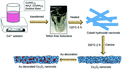 | ||
| Fig. 1 Schematic illustration of the synthesis process of Co3O4 and Au-decorated Co3O4 NRs with the hydrothermal method using an autoclave and calcination approaches. | ||
Characterization of the nanomaterials
The morphologies of the as-synthesized Co3O4 NRs and Au-decorated Co3O4 NRs were characterized using a field-emission scanning electron microscope (FESEM; Zeiss) and transmission electron microscope (TEM; JEOL-JEM-2010) equipped with a charge-coupled device camera (operating voltage = 200 kV). The X-ray diffraction (XRD) patterns of the as-prepared materials were recorded on a Bruker D8 Phaser instrument with Cu-kα radiation (k = 1.54178 Å). Gas sensing measurements were conducted using an in house developed setup at King Abdullah University of Science and Technology (KAUST), Saudi Arabia.Fabrication of transistor-based sensor devices and electrical measurements
We used highly doped 4-inch Si wafers (n++) to make the interdigitated electrode structures that essentially worked as the source and drain contacts of the transistor. Initially, single-sided polished Si wafers were cleaned using a Radio Corporation of America (RCA) process and were transferred immediately into an oxidation chamber for dry oxidation. The thermally grown oxide on top of the wafers was approximately 300 nm and deposited on both sides. The back oxide on the rough side was removed in buffered hydrofluoric acid (BHF). Subsequently, a lithography process was performed on top of the oxide layer using an AZ 5240 positive photoresist and a dark-field mask of interdigitated electrodes (IDE) was used to expose the sample to ultraviolet light at 80 mW. Furthermore, the wafer was developed in an AZ 700 developer for 1 min followed by being washed in deionized water. Finally, we deposited Ti/Au (10/200 nm) using sputtering in a vacuum at 2 × 10⁻⁶ mBar. A lift off process was used to take off the Au and photoresist (sonication in acetone) to realize the source and drain electrodes. The distance between the electrodes was 100 μm and the width of the device was 24![[thin space (1/6-em)]](https://www.rsc.org/images/entities/char_2009.gif) 100 μm. For the deposition, we started with 1 μL of SWCNT solution and drop-cast it on the IDE substrate (FET device), annealing it at 80 °C for 20 min to form the actual channel layer of the device. Then, 2.5 μL of Co3O4 NR solution decorated with Au nanoparticles was drop-cast on top of the SWCNTs in the channel region to form the receptor layer. Fig. 2 illustrates the fabrication process of the transistor-based sensor device using the as-synthesized Co3O4 NRs and Au-decorated Co3O4 NRs.
100 μm. For the deposition, we started with 1 μL of SWCNT solution and drop-cast it on the IDE substrate (FET device), annealing it at 80 °C for 20 min to form the actual channel layer of the device. Then, 2.5 μL of Co3O4 NR solution decorated with Au nanoparticles was drop-cast on top of the SWCNTs in the channel region to form the receptor layer. Fig. 2 illustrates the fabrication process of the transistor-based sensor device using the as-synthesized Co3O4 NRs and Au-decorated Co3O4 NRs.
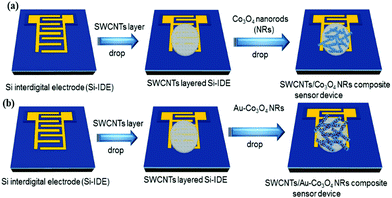 | ||
| Fig. 2 Scheme illustrating the flow of the fabrication process (sensor devices) using (a) Co3O4 NRs and (b) Au-decorated Co3O4 NRs. The red spots on the NRs correspond to Au nanoparticles. | ||
The full length troponin-T protein was purchased from ABCAM. The solutions of streptavidin and troponin-T were prepared in PBS (phosphate buffer saline, pH = 7.4) in 1× dilution using deionized distilled water from a Millipore water purification system. To perform the bio-functionalization during the experiment tiny amounts of streptavidin protein (∼1 μL) were first attached to the surface followed by immobilization of the biotinylated DNA aptamer using the drop-casting method. Binding between the aptamer and streptavidin was facilitated using biotin–streptavidin chemistry. Finally, the target analyte cTnT (∼1 μL) was introduced into the device and the change in the electrical characteristics of the FET was measured and analyzed further. The above sequence was repeated for multiple runs for varying conditions, such as different gate bias voltages, thin-film thicknesses, and target concentrations.
Results and discussion
Morphological and structural characterization
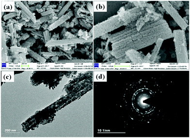
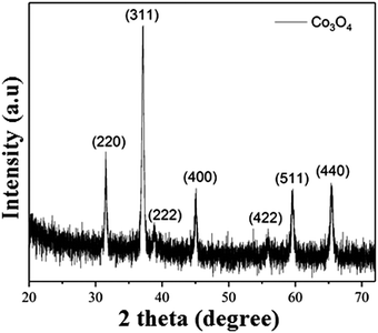
Co3O4 NRs were synthesized using a one-step hydrothermal method (a detailed explanation was provided in the previous section). The morphology and structure of the as-synthesized Co3O4 NRs and Au–Co3O4 NRs obtained after calcination were examined using the FESEM. Fig. 3a and b display FESEM images of the hydrothermally synthesized Co3O4 nanoparticles, which clearly indicate that the products consisted of numerous rod-like structures. The obtained Co3O4 NRs had a diameter in the range of 100–200 nm and length up to 0.5–2 μm. Furthermore, it can be seen that the primary particles of which the Co3O4 NRs are composed were in the range of 40–60 nm. The TEM image in Fig. 3c further demonstrates the morphology of the Co3O4 NRs. It can be seen that the Co3O4 nanoparticles are aggregated during thermal treatment but still the Co3O4 NRs appears to be porous structures. The corresponding selected area electron diffraction (SAED) pattern shown in Fig. 3d further confirms the formation of polycrystalline structures of the Co3O4 NRs corresponding to the cubic Co3O4 phase. The Co3O4 porous NR structures were formed during the oxidation process of Co(OH)x(CO3)y·nH2O according to the following reaction:33,34 | (1) |
| NH2CONH2 + H2O → 2NH3 + CO2 | (2) |
| CO2 + H2O → CO32− + 2H+ | (3) |
| NH3·H2O → NH4+ + OH− | (4) |
 | (5) |
 | (6) |
Characterization of pure Au-decorated Co3O4 NRs
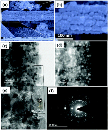
To compare the sensing performance, Au NPs were deposited on the as-synthesized Co3O4 NRs by a deposition–calcination method as described in the synthesis procedure. Fig. 5a is the FESEM image of 1 mL Au-decorated Co3O4 NRs.From these figures, it is evident that small Au NPs were deposited throughout the Co3O4 NR surface after Au nanoparticles were decorated on the Co3O4 NR surface, and are distributed well across the whole surface.
From Fig. 5b, numerous tiny white spherical particles (representing Au nanoparticles) were assembled on the Co3O4 NR surface, which had an average size in the range of 3–5 nm.
Fig. 5d shows the HAADF-STEM image of the 1-Au-loaded Co3O4 NRs, which further confirmed the deposition of Au NPs. Fig. 5e shows the HR-TEM image of the 1-Au-loaded Co3O4 NRs, which was recorded from the black dotted box as shown in Fig. 5c. It clearly shows the lattice fringes of Au and Co3O4, respectively.
Also, Fig. 5f shows the SAED pattern of the 1-Au-loaded Co3O4 NRs indicating the polycrystalline nature of the prepared materials. Fig. 6(a–d) shows the morphologies of as prepared different variations of Au deposited Co3O4 NRs depending on the amount of HAuCl4 from 0.5 to 2 mL. It can be seen that after increasing the loading amount of HAuCl4 to 1.5 mL, the small Au NPs were fully dispersed throughout the Co3O4 NR surface. After further increasing the loading amount of HAuCl4 to 2 mL, the size of the Au NPs increased and they agglomerated on the surface of the Co3O4 NRs.
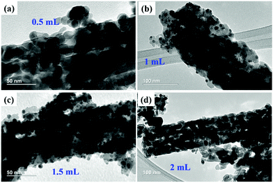 | ||
| Fig. 6 TEM images of (a) 0.5-Au/Co3O4 NRs, (b) 1-Au/Co3O4 NRs, (c) 1.5-Au/Co3O4 NRs, and (d) 2-Au/Co3O4 NRs. | ||
Sensing measurements
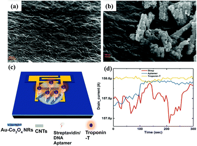
We extracted the transient response of the CNT-based FET device over a period of 5 min (optimized) at multiple stages. The corresponding SEM images of the device are shown in Fig. 7, where we depicted the device deposited with SWCNTs alone (Fig. 7a) and SWCNT/Au–Co3O4 NRs (Fig. 7b) separately. Further analysis was conducted as per the data generated from bare devices and the targeted bioanalyte bound devices. An interesting observation was made toward the end, and the results were in agreement with our previous study on the ZnO platform.24 Initially, control experiments were performed to detect the target analyte with SWCNTs alone, as shown in Fig. 7d.We did not observe any change in the drain current of the device after functionalization of the surface and after introducing cTnT onto the functionalized surface. Next, the Co3O4 NRs were introduced on top of the SWCNTs as a receptor layer, essentially forming a complete bilayer, and the immobilization steps were performed accordingly. In a relevant study, CNTs were used as a channel material along with receptor layers in a FET configuration with a primary focus on chemical sensing.35 Furthermore, in some reports, modified CNTs have been directly used as a channel/sensing layer. For example, Gomes-Filho et al. reported the use of carboxylated CNTs (C-CNTs) for the detection of cTnT,36 where the amine group in polyethyleneimine allowed covalent binding between antibodies and COOH-CNT. Similarly, Barbara et al. reported using NH2-CNT on top of a PET sheet for the detection of cTnT, where the carboxylic group was present on the anti-cTnT antibodies.37
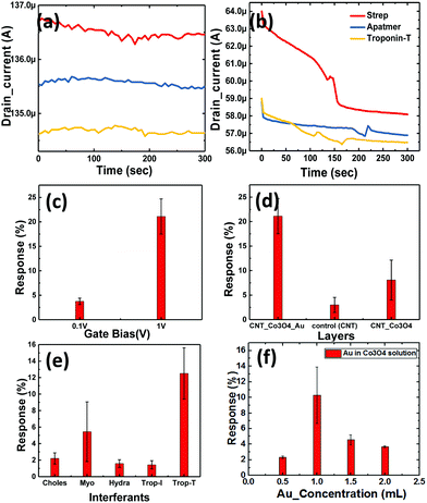
Thus, for transduction to occur, the presence of a binding group is essential for successful detection. Thus we employed another approach with SWCNT/Co3O4 (bilayer-1) and immobilized both streptavidin and the DNA aptamer on it, and then it was tested for cTnT. We observed a change of approximately 1.5% in the drain current from the baseline, as shown in Fig. 8a. This slight change could be attributed to the presence of Co3O4 NRs. Similarly, as shown in Fig. 7c, another bilayer consisting of Au nanoparticle-embedded Co3O4 NRs as a receptor layer was coated on the top of the channel layer of the SWCNTs, forming a combination of SWCNT/Au-Co3O4 (bilayer-2).
This was again immobilized as per the standard process and tested for the cTnT analyte. Here, we observed a maximum change of more than 4.2% in terms of the drain current change from the baseline, as shown in Fig. 8b. Thus, we recorded an increase in sensitivity of more than 250% with the new receptor layer embedded with Au nanoparticles. A DNA aptamer is well known to engender a negative charge in the surface of semiconductors, and thus its functionalization on the p-type channel layer accumulates electrons and reduces the channel current. Furthermore, the interaction between cTnT and the immobilized DNA aptamer leads to a conformational change in the secondary structure of the aptamer, which brings in a more negative charge to the channel layer. A plausible mechanism for the improved sensitivity (in the case of the Au-decorated Co3O4 NRs) could be the synergistic effect of Au nanoparticles and Co3O4 NRs in the channel layer. Here, the Au NPs help in the increased adsorption of negatively charged DNA molecules on the surface of the Co3O4 NRs. Therefore, holes become depleted in the channel because of the enhanced interaction between Au binding sites and secondary structures, eventually leading to a reduced drain current. The Au nanoparticles also play a crucial role in immobilizing biomolecules and enhancing the response signal owing to their high surface area, excellent conductivity and high catalytic properties. Au's high workfunction aids the transfer of electrons from Co3O4 to Au while avoiding any direct charge interaction with the channel layer (SWCNTs). As it can be seen from Fig. 8b, after the immobilization of the DNA aptamer on Au–Co3O4 the drain current reduces (unlike Fig. 8a), which may be due to the difference in work function between gold (5.1–5.47 eV) and Co3O4 (4.5 eV). Thereafter, a further decrease in current is observed after introducing the target cTnT on the Au/Co3O4/CNT composite.
The bar graph in Fig. 8c indicates the dependence of the drain current on the gate bias. Initial runs to test the performance of the novel biosensor were performed with the lowest possible bias voltage of 0.1 V on the drain and gate terminals when the source was grounded, whereas the actual measurements were performed with the drain fixed at 0.1 V and the gate bias increased to 1 V (max in the current device configuration). For an order of magnitude change in the gate voltage, we observed a 5.4-times change in the drain current sensitivity (S) with bilayer-2. Here, we observed that the charge transfer from the DNA aptamer to Co3O4 resulted in reduced conduction of the device. This was because of the presence of a negative phosphate group in the DNA, which contributed to the electron doping in both combinations (bilayer-1 and -2). However, the further decrease in drain current was attributed to the presence of Au nanoparticles, because they efficiently catalyzed the oxidation and the corresponding response obtained with different bilayers can be seen in Fig. 8d. The response time of the device was 2 min, and 50% response was achieved in 15 s. Once the platform was ready, the entire process of immobilization and testing could be performed in 10 min. In addition, the devices can be reused for multiple runs of cTnT detection or any similar marker for other biosensing activities. Selectivity studies have been performed with different biomarkers like cholesterol (choles), myoglobin (myo), hydrazine (hydra) and troponin-I (cTnI) as shown in Fig. 8e. We considered biomarkers like myo and cTnI based on previous reports for the AMI condition and the other biomarkers are irrelevant to AMI. Our device was highly selective towards cTnT detection and responded with minimal intensity to the other biomarkers mentioned above. However, the response to myoglobin was 50% of that of cTnT which can be abbreviated to the myoglobin response lagging to cTnT where the latter immediately spikes in the blood after the onset of AMI and settles down gradually.
Effect of the Au concentration used for the decoration of Co3O4 NRs
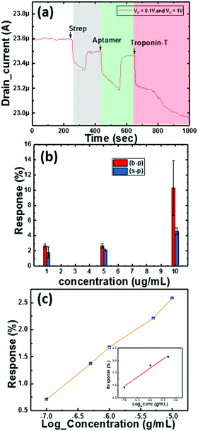
Here, we also made measurements with multiple Co3O4 NRs loaded with different concentrations of Au nanoparticles (as mentioned in Section 2). The obtained results are shown in Fig. 8f and clearly depict the influence of the amount of Au NPs in the system. We further observed that the deviation in the response to troponin-T is high for the optimized concentration of Au on the Co3O4 NRs and also realized that the response degrades with heavier loading. The 1.5-Au/Co3O4 NR and 2-Au/Co3O4 NR devices showed relatively lower responses and the plausible explanation could be the aggregation and large particle formation of Au NPs, which lowers the catalytic activity. Also, the lower availability of catalytic surface sites of Co3O4 NRs in the 1.5-Au/Co3O4 NR and 2-Au/Co3O4 NR samples also might be another reason for the lower responses. Thus, we conclude that 1 mL of Au in the Co3O4 NR solution during the synthesis yields good results and is an optimum value for the efficient response of the device.The measurements in Fig. 9 were performed under continuous gate and drain biases, unlike in Fig. 6 and 7, where both the gate and drain biases were switched off before every step of the protocol. The motive behind such a measurement was to understand the influence of bias stress during the execution of the protocol. We observed no differences in the readings of drain current for switching and continuous gate biases. Furthermore, the response clearly distinguished between three different concentrations, low (approx. 1 μg mL−1), medium (5 μg mL−1) and high concentration immobilization (approx. 10 μg mL−1), of the target cTnT. From Fig. 9a, it is evident that the response of the drain current decreases as the concentration of cTnT increases, and high concentrations of the DNA aptamer and cTnT had similar changes, as observed in Fig. 9b.
We performed sensitivity studies on the device with multiple concentrations of troponin-T as shown in Fig. 9c. These measurements belong to the final step of the entire process of sensing activity and are presented on a log scale (x-axis). The measured LOD of the device is 0.1 μg mL−1 with the maximum concentration being 10 μg mL−1. Fig. 9c illustrates the variation of the response with increasing concentration of the cTnT analyte covering the whole range. The inset in Fig. 9c corresponds to the linear response range for cTnT and was crucial in determining the LOD. We observed negligible changes in the drain current characteristics for a concentration below the LOD as the optimized receptor concentration was not enough to generate adequate signal. In our previous work,24 we took the approach of a TFT with ZnO layers, where the response depends completely on the surface interaction. In the current study, as stated earlier, our target was to reduce the sensor element size to analyte level to improve the sensitivity and thus we carried our experiments with nanoparticles and nanorods that essentially improve the overall surface area for interaction.
Studies were conducted on three channel layers of the FET, SWCNTs (control), bilayer-1, and bilayer-2, to observe the responses to cTnT. We used Co3O4 NRs, a p-type material, for the first time and concomitantly observed an increase in the device sensitivity with Au NP decoration. Morphological studies conducted using FESEM and TEM confirmed the nanostructures and presence of Au nanoparticles. Similarly, electrical characterization helped in understanding the performance of the device through the drain current to detect the AMI condition. Table 1 classifies the AMI detection capability using troponins with different FET platforms. Both cTnI and cTnT have been considered for the comparison. Our Au-decorated Co3O4 NR based FET showed a high response (250%) with a sample volume of 1 μL (0.1 μg mL−1) of target analyte cTnT.
| Target analyte | Device | LOD (μg mL−1) | Sensitivity | Sample volume (μL) | Selectivity |
|---|---|---|---|---|---|
| cTnT25 | ZnO FET | 10 | 0.15 μA | 10 | No |
| cTnI38 | SnO2 FET | 0.02 | NA | 30 | No |
| cTnT39 | SiNW FET | 0.01 | 25% | NA | Yes |
| cTnI3 | SWCNT_Au FET | 1.00 × 10⁻⁶ | 14% | NA | No |
| cTnI40 | FET | 0.02 | 6.40% | 50 | No |
| cTnT [our work]41 | SWCNT/Au–Co3O4 FET | 0.1 | 0.5 μA (250%) | 1 | Yes |
Further, we observed that the FETs developed with complex CMOS technology performed well in terms of the LOD. Thus we consider that our device has limitations in detecting lower concentrations of cTnT but we fared well in using lower sample volume and selectivity. Among five different target analytes, the Au-decorated Co3O4 NR based FET was highly sensitive for troponin-T alone. Our device capability is in the range of physiological concentration (<14 ng L−1), but still higher sensitivities can be achieved through controlled deposition techniques during the immobilization and identification phases. In addition, implementation of processes like nanoimprint lithography kinds of techniques for the proposed material combination might help in improving the sensitivity and achieving the desired LODs. In addition, tests were conducted with liquid drops one on top of the other to check the compatibility of the Au–Co3O4 in multielectrode probe systems like screen printed electrodes (PalmSens),41 where the solutions can be contained. The results confirmed that a test platform co-existing with PalmSens can be utilized to build a hybrid system. This can eventually be helpful in elevating the current platform to a system embedded with pattern recognition with improved detection accuracy.
Conclusions
Here, we successfully demonstrated a versatile and robust SWCNT FET device modified with nanostructures and an aptamer to detect cTnT. Bilayer-2 proved to be the most sensitive layer because of the synergistic combination of Au nanoparticles decorated on top of the Co3O4 NRs. In addition, this was the first time that Co3O4 NRs, a p-type semiconductor, were used in the detection of the AMI condition through cTnT detection. Transient analysis was performed during surface immobilization and testing to observe the changes induced in the drain current (ID). We also evaluated the performance of the sensor platform at three different concentrations (1, 5 and 10 μg mL−1), and significant changes were observed. The LOD of the sensor was 0.1 μg mL−1 with a sample volume of 1 μL and the sensitivity of the proposed sensor was 0.5 μA μg−1 mL−1, which increased by approximately 250% compared with pure Co3O4 NRs. In addition, the drain current sensitivity ratio at different gate biases (S(0.1)/S(1)) was found to be 5.4. As compared to other devices the limitation in our device is its LOD capability and this can be improved by altering the fabrication process in the future course of this work. The proposed DNA aptamer-based sensor system is novel and can be developed into an integrated and high-throughput system.Conflicts of interest
The authors declare that they have no competing interests.Acknowledgements
We thank Ulrich Buttner of Microfluidic Lab, part of the Nanofabrication Core Lab, King Abdullah University of Science and Technology (KAUST), Saudi Arabia for providing his assistance in the project.Notes and references
- J. E. Adams, K. B. Schechtman, Y. Landt, J. H. Ladenson and A. S. Jaffe, Clin. Chem., 1994, 40, 1291–1295 CAS.
- H. A. Katus, A. Remppis, F. J. Neumann, T. Scheffold, K. W. Diederich, G. Vinar, A. Noe, G. Matern and W. Kuebler, Circulation, 1991, 83, 902–912 CrossRef CAS.
- R. V. Sharma, N. K. Puri, R. K. Singh, A. M. Biradar and A. Mulchanadani, Appl. Phys. Lett., 2013, 103, 203703 CrossRef.
- V. V. Shumyantseva, L. V. Sigolaeva, L. E. Agafonova, T. V. Bulko, D. V. Pergushov, F. H. Schacher and A. I. Archakov, J. Mater. Chem. B, 2015, 3, 5467–5477 RSC.
- D. K. Agarwal, A. Prasad, M. Vinchurkar, S. Gandhi, D. Prabhakar, S. Mukherji and V. R. Rao, Appl. Nanosci., 2018, 8, 1031–1042 CrossRef CAS.
- X. Zhang, H. Lv, Y. Li, C. Zhang, P. Wang, Q. Liu, B. Ai, Z. Xu and Z. Zhao, J. Mater. Chem. B, 2019, 7, 1460–1468 RSC.
- S. Sivashankar, C. Sapsanis, U. Buttner and K. N. Salama, Electron. Lett., 2015, 51, 1746–1748 CrossRef.
- I. Lee, X. Luo, J. Huang, X. T. Cui and M. Yun, Biosensors, 2012, 2, 205–220 CrossRef CAS.
- G. Cabral-Miranda, E. Yamashiro-Kanashiro, M. Gidlund and M. G. F. Sales, J. Mater. Chem. B, 2014, 2, 477–484 RSC.
- S. G. Surya, S. Nag, N. M. Duragkar, D. Agarwal, G. Chatterjee, S. Gandhi, S. Patil, D. K. Sharma and V. R. Rao, J. Low Power Electron., 2012, 8, 346–352 CrossRef.
- N. Akhtar, M. Y. Emran, M. A. Shenashen, H. Khalifa, T. Osaka, A. Faheem, T. Homma, H. Kawarada and S. A. El-Safty, J. Mater. Chem. B, 2017, 5, 7985–7996 RSC.
- M. Li, H. X. Tang and M. L. Roukes, Nat. Nanotechnol., 2007, 2, 114 CrossRef CAS.
- T. Hirao, M. Furuta, T. Hiramatsu, T. Matsuda, C. Li, H. Furuta, H. Hokari, M. Yoshida, H. Ishii and M. Kakegawa, IEEE Trans. Electron Devices, 2008, 55, 3136–3142 CAS.
- A. C. M. De Moraes and L. T. Kubota, Chemosensors, 2016, 4, 20 CrossRef.
- Y.-W. Huang, C.-S. Wu, C.-K. Chuang, S.-T. Pang, T.-M. Pan, Y.-S. Yang and F.-H. Ko, Anal. Chem., 2013, 85, 7912–7918 CrossRef CAS.
- W. Peng, S. Qu, G. Cong and Z. Wang, Cryst. Growth Des., 2006, 6, 1518–1522 CrossRef CAS.
- D. Sarkar, W. Liu, X. Xie, A. C. Anselmo, S. Mitragotri and K. Banerjee, ACS Nano, 2014, 8, 3992–4003 CrossRef CAS.
- Y.-M. Chu, C.-C. Lin, H.-C. Chang, C. Li and C. Guo, Biosens. Bioelectron., 2011, 26, 2334–2340 CrossRef CAS PubMed.
- K. Kim, C. Park, D. Kwon, D. Kim, M. Meyyappan, S. Jeon and J.-S. Lee, Biosens. Bioelectron., 2016, 77, 695–701 CrossRef CAS.
- S. Pineda, Z. J. Han and K. Ostrikov, Materials, 2014, 7, 4896–4929 CrossRef CAS.
- X. Tong, E. Ashalley, F. Lin, H. Li and Z. M. Wang, Nano-Micro Lett., 2015, 7, 203–218 CrossRef.
- S. K. Arya, S. Saha, J. E. Ramirez-Vick, V. Gupta, S. Bhansali and S. P. Singh, Anal. Chim. Acta, 2012, 737, 1–21 CrossRef CAS.
- Q. Liu, N. Aroonyadet, Y. Song, X. Wang, X. Cao, Y. Liu, S. Cong, F. Wu, M. E. Thompson and C. Zhou, ACS Nano, 2016, 10, 10117–10125 CrossRef CAS.
- M. F. M. Fathil, M. K. M. Arshad, M. N. M. Nuzaihan, S. C. B. Gopinath, A. R. Ruslinda and U. Hashim, IOP Conf. Ser.: Mater. Sci. Eng., 2018, 318, 012031 Search PubMed.
- D. K. Agarwal, M. Kandpal and S. G. Surya, Appl. Surf. Sci., 2019, 466, 874–881 CrossRef CAS.
- S. Elhag, Z. Ibupoto, O. Nour and M. Willander, Materials, 2015, 8, 149–161 CrossRef CAS.
- X. Luo, A. Morrin, A. J. Killard and M. R. Smyth, Electroanalysis, 2006, 18, 319–326 CrossRef CAS.
- R. Ahmad, T. Bedük, S. M. Majhi and K. N. Salama, Sens. Actuators, B, 2019, 286, 139–147 CrossRef CAS.
- R. Ahmad, O. S. Wolfbeis, Y.-B. Hahn, H. N. Alshareef, L. Torsi and K. N. Salama, Mater. Today Commun., 2018, 17, 289–321 CrossRef CAS.
- D. T. Thompson, Nano Today, 2007, 2, 40–43 CrossRef.
- M. Gautam and A. H. Jayatissa, Solid-State Electron., 2012, 78, 159–165 CrossRef CAS.
- S. Zeng, K.-T. Yong, I. Roy, X.-Q. Dinh, X. Yu and F. Luan, Plasmonics, 2011, 6, 491 CrossRef CAS.
- H. Nguyen and S. A. El-Safty, J. Phys. Chem. C, 2011, 115, 8466–8474 CrossRef CAS.
- X.-h. Xia, J.-p. Tu, Y.-q. Zhang, Y.-j. Mai, X.-l. Wang, C.-d. Gu and X.-b. Zhao, RSC Adv., 2012, 2, 1835–1841 RSC.
- B.-C. Kang, B.-S. Park and T.-J. Ha, Appl. Surf. Sci., 2019, 470, 13–18 CrossRef CAS.
- S. Gomes-Filho, A. Dias, M. Silva, B. Silva and R. Dutra, Microchem. J., 2013, 109, 10–15 CrossRef CAS.
- B. V. Silva, I. T. Cavalcanti, M. M. Silva and R. F. Dutra, Talanta, 2013, 117, 431–437 CrossRef CAS.
- Y. Cheng, K.-S. Chen, N. L. Meyer, J. Yuan, L. S. Hirst, P. B. Chase and P. Xiong, Biosens. Bioelectron., 2011, 26, 4538–4544 CrossRef CAS.
- G. J. Zhang, Z. H. H. Luo, M. J. Huang, G. K. I. Tay, E. J. A. Lim and Y. Chen, Int. Electron Devices Meet., 2009, 563–566 CAS.
- T. Kong, R. G. Su, B. B. Zhang, Q. Zhang and G. S. Cheng, Biosens. Bioelectron., 2012, 34, 267–272 CrossRef CAS.
- M. Čadková, V. Dvořáková, R. Metelka, Z. Bílková and L. Korecká, Electrochem. Commun., 2015, 59, 1–4 CrossRef.
Footnote |
| † Equal contribution. |
| This journal is © The Royal Society of Chemistry 2020 |

