
Stable artificial solid electrolyte interphase films for lithium metal anode via metal–organic frameworks cemented by polyvinyl alcohol†
Lishuang
Fan‡
ab,
Zhikun
Guo‡
*a,
Yu
Zhang
*a,
Xian
Wu
a,
Chenyang
Zhao
a,
Xun
Sun
a,
Guiye
Yang
a,
Yujie
Feng
 a and
Naiqing
Zhang
*ab
a and
Naiqing
Zhang
*ab
aState Key Laboratory of Urban Water Resource and Environment, School of Chemistry and Chemical Engineering, Harbin Institute of Technology, China. E-mail: 1021714267@qq.com; zhangchemistry@163.com; znqmww@163.com
bAcademy of Fundamental and Interdisciplinary Sciences, Harbin Institute of Technology, Harbin, 150001, China
First published on 21st November 2019
Abstract
Lithium (Li) metal anodes have shown a huge potential for next-generation energy storage because of the high theoretical specific capacity and negative potential. Nevertheless, due to the change in the volume and the existence of Li dendrites, the application of the Li metal anode is significantly limited. For the purpose of developing a stable Li metal anode to avoid Li dendrite formation, we introduced a stable artificial solid electrolyte interphase (SEI) film, which was prepared by polyvinyl alcohol (PVA) cementing a metal organic framework (Zn-MOF). The environment-friendly and non-toxic PVA acted as a “glue” to cement the rigid Zn-MOF. The artificial SEI film had high Li ion conductivity and excellent flexibility, which is beneficial for uniform lithium flux, inhibiting dendrite growth and easing the volume change. Consequently, benefitting from the safeguard of the Zn-MOF/PVA artificial SEI film, the anode delivered high coulombic efficiency above 97.7% beyond 250 cycles at a current density of 3 mA cm−2.
Introduction
With the increasing requirements of energy density applications in the fields of portable electronic equipment and electric vehicles, the current lithium (Li) ion battery system of graphite anode has been far from being satisfactory because of its low theoretical capacity (372 mA h g−1). Thus, it is urgent to develop new energy storage systems with high energy density as well as a long lifespan.1,2 The Li metal anode is considered the most promising anode material with exceptional theoretical specific capacity (3860 mA h g−1) and extremely negative potential (−3.040 V vs. standard hydrogen electrode).3,4 Battery systems with Li metal as the anode (for instance, Li–S and Li–O2 batteries) are considered to be the most promising next-generation high-specific-energy batteries.5 However, during the cycles of the battery, Li dendrites are easily grown on the surface of the electrode, resulting in an internal short circuit, which can give rise to a thermal runaway. In addition, the vast volume expansion of the electrode causes the electrode to be powdered, thus limiting the application life of the Li anode.In recent years, with the development of nanotechnology, researchers have developed many new strategies to solve the Li dendrite problem, including new energy storage systems,6 liquid electrolyte additives,7,8 solid/polymer electrolytes,9–11 modified separators,12–14 artificial protective layers,15–17 structured anodes18–20 and other methods.21,22 It is well accepted that constructing a stable solid electrolyte interphase (SEI) film is able to restrain Li dendrite formation and improve the cycle stability of the anodes.23,24 Some studies have constructed interfacial SEI films on the surface of Li foils using electrolyte additives and other methods.25 These SEI films will passivate the Li metal and prevent the corrosion of the electrolyte. However, the mechanical robustness of these in situ SEIs is normally unsatisfactory and the volume expansion cannot be effectively mitigated, thereby failing in offering long-term cycling stability for the Li metal anodes.26 As a result, ex situ isolating coatings began to develop.27–29 Admittedly, these ex situ coatings are effective in suppressing side reactions and Li dendrite formation to some extent. However, these artificial SEI films have poor flexibility due to a high mechanical modulus, which will produce cracks in the circulation, and this can limit its cycle life as well.30 Therefore, it is of great significance to develop a Li metal anode SEI film with proper toughness that can effectively buffer the volume change, have a simple preparation process, good interfacial contact, and high Li+ conductivity.
Here, we propose polyvinyl alcohol (PVA) as a “glue” to cement the metal organic framework (Zn-MOF) sheet as a reasonable artificial SEI film. The Zn-MOF constructed in situ on the Cu foil has high ion conductivity, and the large number of polar bonds (O–H, Zn–N) on its surface can adsorb Li+, so that Li+ can rapidly diffuse to the artificial SEI film. Zn-MOF has high mechanical strength and can avoid a Li dendrite puncture. Notably, the Zn-MOF layer has a good electrolyte wettability, which can reduce the surface concentration gradient, and abundant pore channels can be used for effectively screening ions and hindering the anion migration, so as to improve the migration number of Li+ with uniform Li+ flux and inhibit the formation of Li dendrites. PVA is a kind of extremely safe and environment-friendly polymer organic matter, which has no toxic side effects on the human body.31,32 It is almost insoluble in organic solvents and has good film formation. PVA has a high viscosity and high ionic conductivity after adding lithium salt (LITFSI).33 It penetrates into the surface of the Zn-MOF layer by spin-coating and cements it, which does not affect the Li+ conduction of the entire film layer, and also gives it very high flexibility. The artificial SEI film can efficiently adapt to the changes of the volume during the cycle, significantly improve the stability of the Li metal anode, and prolong the cycle period of the battery. Typically, the coulombic efficiency can be maintained to above 97.7% beyond 250 cycles at a high current density of 3 mA cm−2. When the Li metal anode couples with lithium iron phosphate (LiFePO4), the assembled full cells exhibit exceptional performance with better capability retention. The full cell has a stable capacity of 135.3 mA h g−1 after 100 cycles at 1C.
Results and discussion
Fig. 1a expounds the preparation process of the artificial SEI film. Zn-MOF was grown uniformly in situ on the surface of the Cu foil at room temperature through a facility synthesis method.34–36 Next, PVA gel was permeated on the surface of the Zn-MOF by spin-coating. Zn-MOF and PVA are connected by hydrogen bonds. There are a large of protuberances on the Cu foil,37 and a locally high electric field accelerates the growth of Li at the local area, which gradually becomes Li dendrites.38,39 In order to avoid the growth of Li dendrites, we introduce an artificial SEI film of Zn-MOF/PVA on the surface of the Cu foil. Compared to the unprotected Li metal, the artificial SEI film not only contributes to the fast and uniform distribution of Li+ flux on the electrode surface but also reduces the volume expansion, leading to a more uniform Li plating/stripping process (Fig. 1b). The Li+ tends to redistribute again through the compact Zn-MOF/PVA film. Because the Zn-MOF/PVA is insulative, and the Li+ only epitaxial deposit from Cu foil surface.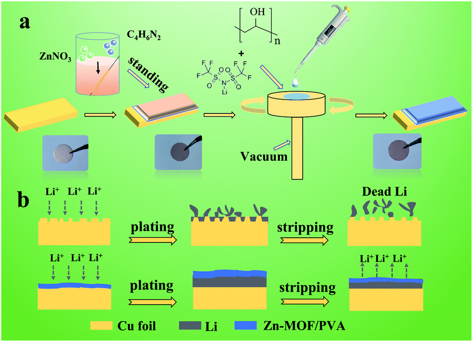 | ||
| Fig. 1 Schematic illustration of (a) the fabrication of the artificial SEI film. (b) The Li plating/stripping behavior on bare Cu foil, and the artificial SEI film protected Cu foil. | ||
In order to verify the successful preparation of the artificial SEI film, an X-ray diffraction (XRD) pattern was used to confirm the crystal structure of the Zn-MOF coated Cu foil. After growing Zn-MOF on the Cu foil, the position of the peaks did not change, indicating that their crystal shapes did not transform, and they could exist stably on the surface of the Cu foil. The special diffraction peaks of Zn-MOF appear at 5–35°, indicating that it crystallizes in the orthorhombic system, which matches well with the early literature (Fig. 2a).40 The XRD patterns of Cu@Zn-MOF/PVA and Cu@PVA are shown in Fig. S1.† The XRD peak position of PVA is about 19.5°. In the ball-and-stick model of Zn-MOF as shown in Fig. 2b, the Zn–MeIm–Zn bonds are substituted for sticks and the hydrogen atoms are ellipses. The polyhedron was built on a ZnN4 unit and there were large Zn–N, C–N polar bonds in Zn-MOF. Zn-MOF is a two-dimensional (2D) crystal in formation and the bridging for the 2D-structure occurs through hydrogen bond between MeIm molecules. Fig. 2c shows the adsorption and desorption curve of N2. The P/P0 curve contains H4 hysteresis, which generally occurs in adsorption materials with mixed micropores and mesoporous pores. The internal illustration shows the pore diameter distribution curve. The average pore diameter of Zn-MOF is 1.98 nm and the BET specific surface area is 69.78 m2 g−1. The abundant transfer paths and high specific surface area in the Zn-MOF films can provide a uniform lithium ion flux, which is conducive to the rapid diffusion and uniform deposition of Li+.
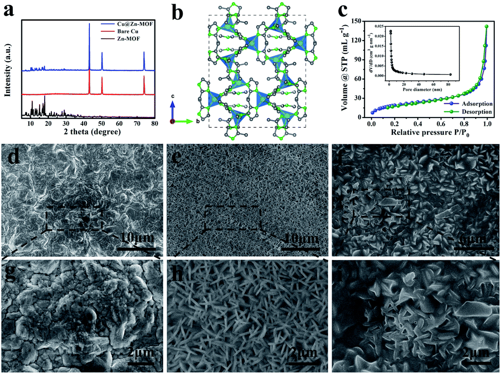 | ||
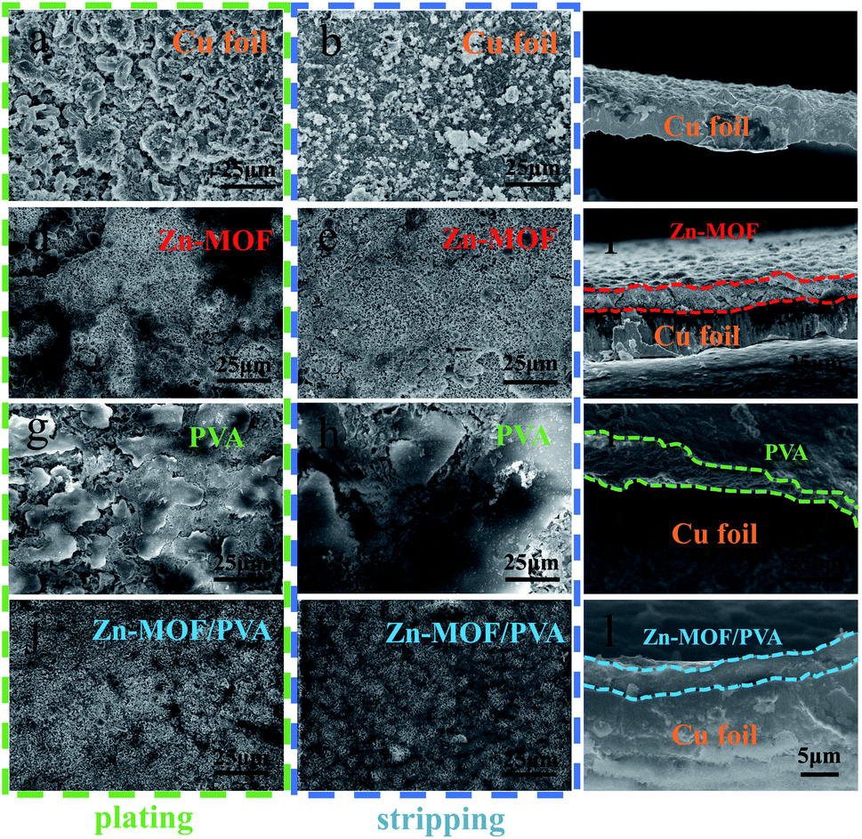
| Fig. 2 (a) XRD patterns of the Zn-MOF, Cu foil, and Cu@Zn-MOF (b) views of the crystal structure (ball-and-stick model) of Zn-MOF. (c) N2 adsorption–desorption isotherm and pore size distribution curves of Zn-MOF. SEM image of (d and g) Cu foil; (e and h) the Zn-MOF SEI film on Cu foil; (f and i) the Zn-MOF/PVA SEI film on Cu foil. | ||
To test the wettability between the electrolyte and Zn-MOF and Zn-MOF/PVA, the electrolyte was dropped into the prepared electrode surface for the contact angle test. The contact angle of the ether-based electrolyte on the surface of Cu foil is 34.2°. As can be seen from Fig. 2e and f, the surface roughness of Zn-MOF and Zn-MOF/PVA is close to each other. Cu@Zn-MOF/PVA had the best hydrophilicity (Fig. S2b†). The contact angle of Cu@Zn-MOF/PVA is larger than that of Cu@Zn-MOF. The results show that the wettability of the electrolyte on the surface of the Cu foil is improved by the modification of the SEI film. Zn-MOF/PVA can enhance the affinity of the electrode/electrolyte interface, and reduce the concentration gradient of the Li ion.41 The apparent resistance of the artificial SEI film was measured by a multifunctional multimeter. Fig. S3a† shows the resistance value of the Cu foil with the Zn-MOF film, which can be seen to be extremely high, proving that Zn-MOF film has electronic insulation characteristics. The resistance value of the bare Cu foil is 0.8 Ω (Fig. S3b†). Cu foil has a high electrical conductivity, which is conducive to electron transfer, while Zn-MOF film is insulated. When Li is deposited, Li+ can only pass through the artificial SEI film to obtain electrons on the surface of the Cu foil and deposit, so Li will deposit between the artificial SEI film and the current collector. The ideal SEI membrane is electron insulating, and the SEI film that we prepared is exactly in line with this point.42
The microstructure was observed by scanning electron microscopy (SEM). Fig. 2e and h show the image of the as-grown Zn-MOF on the Cu foil, where a uniform and compact array layer can be monitored. PVA were filled between the sheets on the surface of the Zn-MOF film (Fig. 2f and i). Fig. S4† shows that the thickness (3.1 μm) of Zn-MOF could be controlled easily by changing the crystallization time of Zn-MOF on the surface of the Cu foil in solution, demonstrating the great adjustability and facileness of our method. The thickness of the MOF layer increased as the growth time increased. When the Zn-MOF crystallized on the surface of the Cu foil for 30 minutes, the protective layer thickness was 2.6 μm, while the thickness increased dramatically to 6.1 μm after 3 hours of crystallization. The thickness increased faster with increasing time, and the protective layer became fluffier. Moreover, due to the increase of internal stress, the adhesion of the Zn-MOF film on the surface of the Cu foil decreased. As can be seen from Fig. S5,† Zn-MOF gradually covered the surface of the Cu foil with the extension of time. When growing for 1 hour, the Zn-MOF film covered the Cu foil evenly. However, as time continued to increase, micron-sized flake clusters appeared on the surface, making the surface of the Zn-MOF layer uneven. The reason is as follows: when the Zn-MOF was first grown, it was a heterogeneous nucleation process with a slow crystallization rate. When Zn-MOF covered the Cu foil, the subsequent nucleation belonged to the same nucleation, and the growth rate was greatly improved, making it easier to crystallize.
The surface morphology of the Zn-MOF/PVA artificial SEI film is shown in Fig. S6;† when the content of PVA in the gel solution was low, the adhesion of the Zn-MOF surface to PVA was weak. However, when the content increased to 0.32 wt%, PVA could just fill between the sheets of the Zn-MOF film surface and play a cementing role. As the content continued to increase, the PVA film became so thick that the Zn-MOF was completely covered. The PVA gel solution was thrown out due to the effect of the centrifugal force because the viscosity was weak, and the protective effect of the composite film could not be effectively exerted in this way. When the content increased to 0.48 wt%, the viscosity of the gel solution was too strong, which could not be uniformly coated at the same speed, forming a thick film on the surface. Therefore, the gel solution containing 0.32 wt% PVA with moderate viscosity was selected for spin-coating to prepare the electrode. Fig. S7a† is a schematic diagram of the nanoindentation test and Fig. S7b† shows the curve of the average elastic modulus changing with distance from the surface displacement. When the elastic modulus exceeds 1 GPa, dendrite will be inhibited.43 The modulus of the Zn-MOF/PVA artificial SEI film was 7.5 GPa and thus, the dendrites were inhibited significantly.
The Li+ transfer number was calculated by the Bruce–Vincent formula.44–46 The time–current curve is shown in Fig. 3a, and the impedance change before and after steady state (Fig. S8†). The cell system of the Cu@Zn-MOF/PVA electrode (0.732) had a higher Li+ transport performance compared with the Cu foil (0.606), Cu@Zn-MOF (0.697) and Cu/PVA (0.656). There is a balance between Li+ and anion in the electrolyte, and they migrate in the opposite direction in the charge and discharge cycle.47 There are a large number of polar bonds on the surface of Zn-MOF that can adsorb Li+. The metal center of Zn-MOF generates a complexation effect on the anions, and the lone pair electrons in the C–N bond hinder the migration of the anions. The Zn-MOF film will screen the anions through the channels and the metal activity center, allowing the rapid migration of Li+ and hindering the anion transfer, thus increasing the migration number of Li+.48 When the Zn-MOF surface spin-coating PVA polymer and LiTFSI were added, the local Li+ concentration at the interface of the prepared artificial SEI film increased. Li+ could then be supplemented during deposition in a timely manner, and the migration rate of Li+ at the interface was accelerated. The screening of the Zn-MOF film and the increase of the local Li+ concentration in the interface have a synergic effect on the transfer number of the Zn-MOF/PVA composite artificial SEI film, so as to improve the transport of Li+ and improve the cycling performance. When the concentration of Li+ at the electrode interface dropped to a certain limit or even zero, Li+ deposited irregularly under the action of a strong negative electric field, and dendrites began to precipitate, which is the main factor leading to a short circuit and battery failure. For this process, the estimated time can be determined by the Sand's time formula,49,50 and the formula shows that the increase of the number of tLi+ extends the Li dendrite growth time. A high transfer number in the Zn-MOF/PVA protected Li anode system can improve Li+ transmission, and Li+ can be supplemented more quickly. Thus, the formation of the space charge area can be greatly alleviated and dendrite growth is inhibited.
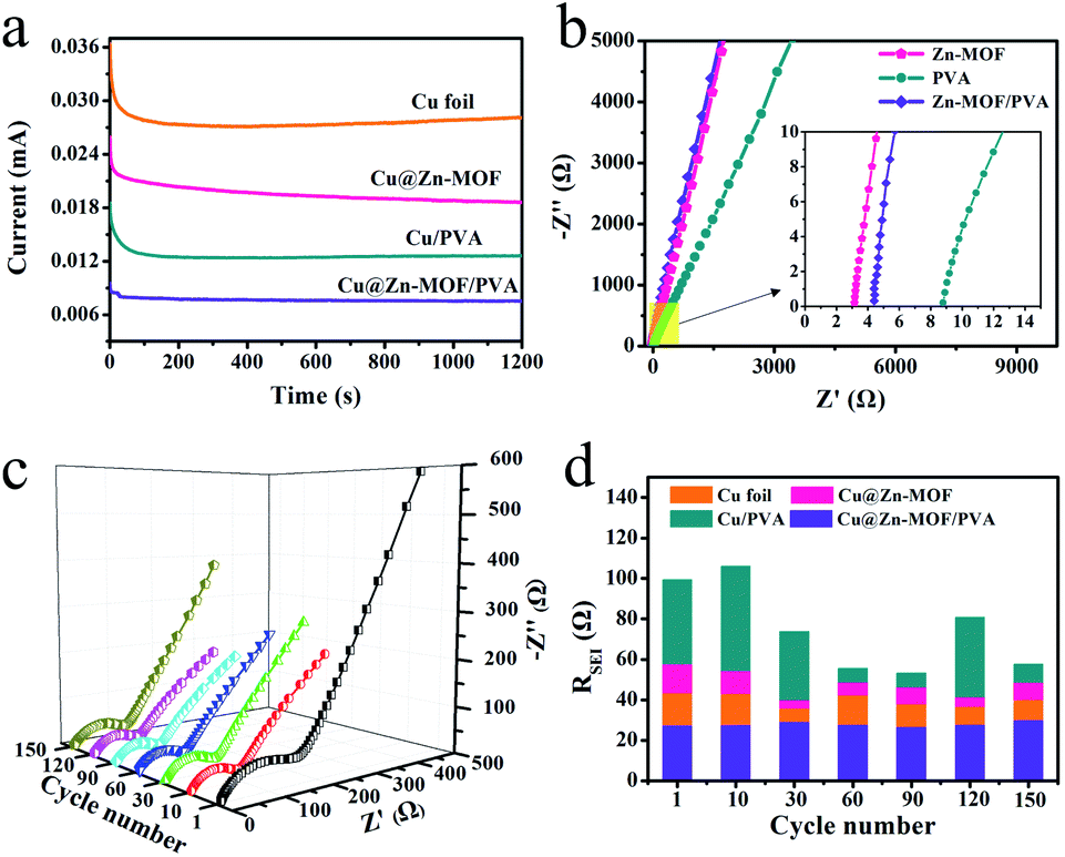 | ||
| Fig. 3 Electrochemical analysis: (a) current–time curve, (b) impedance plots estimating Li conductivity, (c) EIS spectra of the protected Li electrode, and (d) the RSEI value of the cycle number. | ||
Cyclic voltammetry (CV) was executed to confirm the electrochemical behaviours with the artificial SEI film in the presence of Li (Fig. S9†). During the CV cycle, there were only oxidation peaks when lithium was deposited and reduction peaks when it was striped. This indicated that the artificial SEI film would not react with Li during deposition and stripping. In the electrochemical reaction process, Zn-MOF, PVA and the Zn-MOF/PVA composite film were stable in the cycle process. It shows that the SEI film we proposed has chemical stability in the electrolyte. The theoretical decomposition voltage of the Li metal anode was about 0.5 V. Under normal operation conditions, the electrochemical potential of our proposed anode will not exceed 0.5 V, which confirms the rationality of Zn-MOF/PVA as a useful protective layer on the Li metal anode. The Li+ conductivity is one of the vital important parameters for Li plating uniformly. The Li+ conductivity of the artificial SEI film was evaluated by electrochemical impedance spectroscopy (Fig. 3b). The Zn-MOF layer showed a lower resistance compared with the PVA and Zn-MOF/PVA film in high frequency. The calculation analysis showed that the Li+ conductivity of the Zn-MOF film was 0.187 mS cm−1, which is higher than the PVA film at 0.102 mS cm−1. The Li+ conductivity of the Zn-MOF/PVA film was 0.147 mS cm−1. The higher conductivity of Li+ was conducive to the rapid transfer of Li+ and the uniform flux of Li+, and thus reduced the formation of the Li dendrites.
The dominance of the Cu@Zn-MOF/PVA electrode in kinetics was analyzed by EIS. We measured the electrochemical impedance curves at different cycle times during Li deposition under an open circuit potential (OCP) to study the resistance changes (Fig. 3d and S10†). Our impedance data was fitted using the software Zsimpwin. According to the typical impedance spectra of the intercalation electrode, as shown in Fig. S11,†Rs reflects a built-up resistance of the separator and electrolyte. C1 and Rct represents the double-layer capacitance and charge transfer resistance, corresponding to the semicircle. Zw is the Warburg impedance related to the effect of Li+ diffusing across the electrode. The electrolyte/electrode interfaces mainly include the SEI film layer, which appears as the sloped line at low frequency.51,52 The SEI layer's capacitance and resistance on the surface of the electrodes are represented by C2, and RSEI corresponds to the semicircle at high frequencies. Values of Rs and Rct are shown in Table S1.† The electrolyte resistance (Rs) starts small and then maintains a constant value. The Rct of Zn-MOF/PVA is more than that of the Cu foil, because Zn-MOF and PVA are insulated. The natural SEI film, Zn-MOF film and Zn-MOF/PVA film have smaller RSEI than the PVA film. The natural SEI and Zn-MOF film RSEI fluctuates greatly in the late cycle, and the fluctuation of the PVA film is the most obvious. This indicates that the SEI film has been destroyed in the later stage. Nevertheless, the Li protected by the Zn-MOF/PVA artificial SEI layer showed a nearly constant RSEI throughout the 150 cycles. The Cu@Zn-MOF/PVA's RSEI during the discharge process is first about 8.26 Ω, and then decreased gradually to a stable value, suggesting the formation of a stable SEI film after the initial plating process. Thus, it is evident that the Zn-MOF/PVA artificial SEI film is beneficial in forming a stable SEI film on the Li metal surface during prolonged battery cycling. This further confirmed the dendrite suppression capability of the artificial SEI film. It is evident that the Zn-MOF/PVA layer is beneficial in forming a stable protective layer on the Li metal surface during prolonged battery cycling.
The coulombic efficiency, which is measured from the ratio of Li plating and Li stripping, is a significant parameter to measure the stability and utilization efficiency of the Li anode in the cycle. It can be seen from Fig. S12† that the Coulomb efficiency of the bare Cu foil fluctuates significantly after 15 cycles, indicating that the dendrites are generated on the surface of the Cu foil. The electrode protected by the Zn-MOF film after 1 hour of growth remained stable, and the coulombic efficiency was still up to 97.2% at the 70th cycle, indicating that the artificial SEI film played a role in inhibiting the lithium dendrites. When the growth time was too long, the Zn-MOF film was thick, which slowed down the diffusion kinetics of Li+, obstructing the transport of Li+ and causing an uneven deposition. We optimized the content of the Li salt in the spin-coated gel as can be seen from Fig. S13.† When the content increased to 0.96 wt%, the cyclic Coulomb efficiency was stable, and the cyclic Coulomb efficiency could be more than 200 times under the condition of 3 mA h cm−2 and 1 mA cm−2. At this time, the Zn-MOF/PVA film plays a good role in protecting the Li metal. As shown in Fig. S14,† the composite film, which was obtained by the spin coated gel containing 3.2 wt% PVA had higher stability, and the coulombic efficiency was more than 97.5% after 100 cycles. A low PVA content would lead to a poor adhesion force on the electrode surface, and the protective effect of the artificial SEI film could not be reflected. The content of PVA was too high because the increase of viscosity would make the film too thick, affecting the transmission of Li+.
To further verify the protective effect of the composite artificial SEI film, the coulombic efficiency of the electrode under different artificial SEI film protections was compared. As shown in Fig. 4a, Cu@Zn-MOF/PVA had a high coulombic efficiency, which was as high as 97.3% at 400 cycles. Conversely, the coulombic efficiency of the unprotected electrode (Cu foil) fluctuated and was only 79.6% after 170 cycles. Due to the destruction of the SEI film, fresh lithium reacted with the electrolytes to consume active Li, resulting in a reduced coulombic efficiency. When the current density was enhanced to 3.0 mA cm−2, the coulombic efficiency of Cu@Zn-MOF decayed quickly to around 80% after 210 cycles (Fig. 4b), while PVA was only 61.5% after 135 cycles, and the bare Cu foil declined more seriously. It is attributed to the high current density inducing an increase in the Li deposition rate, and the electrode surface was more likely to produce a large amount of Li dendrites and dead Li. Amazingly, even at a high current density, the coulombic efficiency of Zn-MOF/PVA was still maintained at 97.7% after 250 cycles, which can indicate that Zn-MOF/PVA can effectively protect the Li anode and improve the utilization rate of Li.
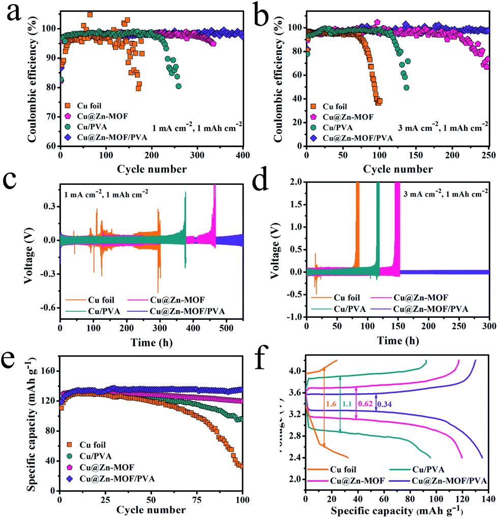 | ||
| Fig. 4 Coulombic efficiency of the artificial SEI protected Cu foil and bare Cu foil at a current density of (a) 1 mA cm−2; and (b) 3 mA cm−2 (cycling capacity 1 mA h cm−2). Voltage profiles of Li plating/stripping in Cu, Cu/PVA‖Li, Cu@Zn-MOF‖Li, and Cu@Zn-MOF/PVA‖Li of (c) 1 mA cm−2; and (d) 3 mA cm−2 (e) cycle performance of the battery at 1C; (f) charge–discharge voltage curve with different anode. | ||
Similarly, for the Li symmetrical cell under 1 mA cm−2 and 1 mA h cm−2 test conditions, the Li@Cu‖Li cell shows a random overpotential undulation, while the Zn-MOF and PVA protected electrodes show the overpotential increasing sharply to different degrees during the cycle process. This could result in a short circuit and lead to the penetration of Li dendrites. However, the Li symmetrical cell protected by Zn-MOF/PVA showed excellent cycling stability, which maintained the overpotential of 51.7 mV for 580 h. These results further prove that dendrites can be inhibited. When the current density increased to 3 mA cm−2, the overpotential is only 42.1 mV after 300 hours of stable cycle. This is because the composite film fuses the screening function of Zn-MOF and the flexibility of PVA, which not only makes the Li+ flux uniform but also reduces the expansion of volume, thus inhibiting the dendrites of Li and constructing a stable Li metal anode. We assembled full cells in the form of coin cells using LiFePO4 (LFP) as the cathode to verify the cycling capability of the Li metal anode. The 5 mA h cm−2 Li was predeposited on the current collector as the anode. As shown in Fig. 4e, we studied the cycling capability of the cells at 1C (∼170 mA g−1). The specific capacity of the cell with the Li@Cu anode delivered a dramatic attenuation to about 32.4 mA h g−1 after 100 cycles, suggesting a low utilization of the Li. In contrast, the full cell with Cu@Zn-MOF and Cu/PVA delivered a capacity of 119.7 mA h g−1 and 95.6 mA h g−1 after 100 cycles, respectively. Remarkably, the Cu@Zn-MOF/PVA anode showed a better cycling that delivered a capacity of 119.3 mA h g−1 at first cycle and 135.3 mA h g−1 after 100 cycles, which signified that the Zn-MOF/PVA could suppress the formation of Li dendrites and dead Li. The data of the full battery assembled with commercial lithium are shown in Fig. S15,† with a specific capacity of 127.1 mA h g−1. The charge and discharge voltage curve of the battery can effectively reflect the polarization degree of the electrode. The LFP/Cu@Zn-MOF and LFP/Cu cell deliver an almost similar low voltage polarization at 1C. The polarization voltages of the Cu@Zn-MOF and Cu@PVA remarkably increase from 218 mV to 620 mV, 1.1 V and 1.6 V, indicating that the ohmic resistance in the battery increases, and loose “dead lithium” accumulates on the electrode surface, resulting in an irreversible loss of capacity and increase of the interface resistance. However, Cu@Zn-MOF/PVA increases from 218 to 340 mV after 100 cycles, indicating a very low electrode polarization and a stable electrode surface.
The coin cells were disassembled to study the Li morphology after cycles of Li depositing/stripping at the current density of 1.0 mA cm−2. There are large filamentous dendrites on the bare Cu foil surface after the first plating (Fig. S16a†). As shown in Fig. 5, when the Cu foil electrode is cycled 50 times, the SEI layer regeneration inevitably consumes Li and electrolyte, resulting in a low coulombic efficiency and short lifespan. When Li is deposited under the Zn-MOF, the rigid Zn-MOF film will crack due to the stress and the Zn-MOF can be broken by prolonged circulation (Fig. 5d). Part of Li is deposited below the PVA film, and the other part is exposed due to the shedding of the PVA film. Due to its weak mechanical strength and poor compatibility with the interface of the Cu foil, most PVA films are damaged and fall off, which cannot effectively protect the Li metal. However, with the protection of Zn-MOF/PVA, Li+ could distribute uniformly on the surface with dendrite free morphology. After the 50th deposition of Li, the original morphology of the electrode surface remained unchanged after Li stripping, and the cross-sectional view also showed that the protective layer was uniform and completely attached to the Cu foil (Fig. 5l). This shows that the Zn-MOF/PVA film has good mechanical strength and excellent flexibility, which can restrain the infinite volume alter of Li, thereby improving the utilization and stabilizing the Li metal anode.
 | ||
| Fig. 5 Top-view SEM images of Li plating/stripping after 50 cycles and cross-sectional after Li stripping on (a–c) Cu foil, (d–f) Cu@Zn-MOF, (g–i) Cu@PVA, (j–l) Cu@Zn-MOF/PVA with 1 mA cm−2, 1 mA h cm−2. | ||
Experimental
Electrode preparations
Zinc nitrate hexahydrate (Zn(NO3)2·H2O, Sinopharm Chemical Reagent Co., Ltd, China, 98%), 2-methylimidazole (Aladdin, China, 98%), polyvinyl alcohol (PVA, Sinopharm Chemical Reagent Co., Ltd, China, alcohol solubility: 99.8–100%) and lithium difluoromethane sulfonyl imide (LiTFSI, Shanghai Sigma Aldrich Co., Ltd, China, 99%) were used without any purification process. The copper foil was taped to the glass sheet to expose only one side, and then washed with deionized water and ethanol for more than 3 times.1.98 mmol of Zn(NO3)2·6H2O and 15 mmol of 2-methylimidazole were added in 40 mL deionized water, and the following mixture was stirred by magnetic stirring until it dissolved at room temperature. Then, the Zn(NO3)2·6H2O solution was decanted into the 2-methylimidazole solution immediately and a piece of 2 cm × 4 cm cleaned Cu foil was placed in the above mixing solution quickly. Being kept for a period of time, the Cu foil was rinsed with deionized water and dried at room temperature. The Zn-MOF artificial SEI films were obtained. PVA alcohol particles at 0.5 g, 1.0 g and 1.5 g to were each added to 30 mL deionized water, and allowed to dissolve for 1 hour, and then stirred at 96 °C until all particles were dissolved. The solution cooled to room temperature was transparent. LiTFSI was then added at 0.15 g, 0.3 g, 0.45 g and 0.6 g into 5 mL gel solutions with different PVA mass fractions, and the mixture was stirred and dissolved for 20 minutes. The Cu@Zn-MOF prepared in the early stage was cut to a 12 mm round sheet, and 50 μL PVA gel was applied on it. The PVA gel was to infiltrate the whole surface of the round sheet, and then it was placed on the homogenizer for spin-coating. The spin-coating conditions were as follows: first spinning for 3 seconds at a rotation speed of 900 rpm, and then spinning for 1 minute at 4000 rpm. After spin coating, the samples were dried in oven at 50 °C for half an hour and cooled to room temperature for later use.
Electrochemical measurements
All electrochemical measurements were carried out using CR2025 or CR2032 type coin cells assembled in an Ar-filled glove box with O2 and H2O content below 1.0 ppm. For the coulombic efficiency test, metallic Li was used as a reference and working electrodes. In addition, the ether-based electrolyte of 1 M LiTFSI in DOL/DME (1![[thin space (1/6-em)]](https://www.rsc.org/images/entities/char_2009.gif) :1 by volume) with 2 wt% LiNO3 as additive was utilized, which was bought from a dodo reagent network (http://dodochem.net/). During each galvanostatic cycle, the discharge current density of 1 mA cm−2 (time of 1.0 hour)/3 mA cm−2 (time of 20 min) and the charge cut-off voltage of 0.5 V were set for the lithium plating and stripping. Before testing the Li‖Li symmetrical cells, Li of 5 mA h cm−2 was first deposited into the current collector. The full cells were assembled with LiFePO4 as the cathode, and the 5 mA h cm−2 Li was predeposited on the Cu foil, Cu@Zn-MOF, Cu/PVA and Cu@Zn-MOF/PVA electrodes at 0.5 mA cm−2 as anodes, with Celgard 2400 membrane as the separator. 1.0 M LiPF6 in 1:1 vol/vol EC/DEC was used as the electrolyte. 80 wt% LFP powders, 10 wt% PVDF binder, and 10 wt% Super P conductive carbon black were mixed to form a slurry which concentration was regulated by NMP. The slurry was further blade coated onto the Al foils, and then dried at 60 °C for 24.0 h to get the LiFePO4 cathode. The galvanostatic charge–discharge tests were carried out at currents with a cut-off voltage range from 2.4 to 4.2 V. Cells were discharged and charging was performed by a NEWARE BTS-610 (Neware Co. Ltd, China) battery tester.
:1 by volume) with 2 wt% LiNO3 as additive was utilized, which was bought from a dodo reagent network (http://dodochem.net/). During each galvanostatic cycle, the discharge current density of 1 mA cm−2 (time of 1.0 hour)/3 mA cm−2 (time of 20 min) and the charge cut-off voltage of 0.5 V were set for the lithium plating and stripping. Before testing the Li‖Li symmetrical cells, Li of 5 mA h cm−2 was first deposited into the current collector. The full cells were assembled with LiFePO4 as the cathode, and the 5 mA h cm−2 Li was predeposited on the Cu foil, Cu@Zn-MOF, Cu/PVA and Cu@Zn-MOF/PVA electrodes at 0.5 mA cm−2 as anodes, with Celgard 2400 membrane as the separator. 1.0 M LiPF6 in 1:1 vol/vol EC/DEC was used as the electrolyte. 80 wt% LFP powders, 10 wt% PVDF binder, and 10 wt% Super P conductive carbon black were mixed to form a slurry which concentration was regulated by NMP. The slurry was further blade coated onto the Al foils, and then dried at 60 °C for 24.0 h to get the LiFePO4 cathode. The galvanostatic charge–discharge tests were carried out at currents with a cut-off voltage range from 2.4 to 4.2 V. Cells were discharged and charging was performed by a NEWARE BTS-610 (Neware Co. Ltd, China) battery tester.
The electrochemical impedance spectra (EIS) of the coin cells were measured on a CHI660E workstation at frequencies from 105 to 1 Hz, and an AC signal was 10 mV. The CV was carried out on a CHI660E electrochemical workstation with a scan speed of 0.1 mV s−1.
The lithium ion transference number in the battery system, which uses an artificial SEI film coated Cu foil and Cu foil as the electrode, was determined with chronoamperometry at a constant potential. A separator was used to separate between one Li metal electrode and Cu, Cu@Zn-MOF, Cu/PVA or the Cu@Zn-MOF/PVA electrode. The lithium ion transference number was calculated according to the equation:
| tLi+ = Is(V − IoRo)/Io(V − IsRs) |
The lithium ionic conductivity of the artificial SEI film was measured from EIS with the CHI660E electrochemistry workstation. A separator wetted with electrolyte was between a stainless steel electrode and the Cu foil, Cu@Zn-MOF, Cu/PVA or Cu@Zn-MOF/PVA electrode, and the ionic conductivity was calculated according to the following equation:
| σ = I/AR |
Characterization
The crystal structures of the samples were confirmed by a PAN analytical X'Pert PRO X-ray diffraction instrument using monochromated Cu Kα radiation operating at 40 mA and 40 kV. A Hitachi SU8010 scanning electron microscope was used to characterize the morphology at 5 kV. The contact angle was measured by the POWERACH JC2000D5 contact angle meter. The drop of electrolyte onto the surface of the sample gradually stabilized after 10 seconds. The N2 adsorption/desorption isotherm was obtained with ASAP 2020 (Micromeritics). The corresponding pore distribution was determined by the Brunauer–Emmett–Teller method.Elastic modulus test
The elastic modulus of the artificial SEI films was measured with a nanoindentation test (Keysight Technologies, Inc. G200 Nano Indenter). Due to the effect of the basement effect, the testing depth of the effective information is below 10% of the total film. The indentation was measured at four locations on the prepared film and then averaged. The surface approach velocity and distance were 2 nm s−1 and 3 μm, respectively. Poisson's ratio for the test was 0.18.Conclusions
In summary, aiming at the problem that the SEI film formed by Li metal itself cannot effectively inhibit lithium dendrites in the circulation process, a Zn-MOF coating was designed and put forward which was grown in situ on the surface of a copper foil. The surface of the Zn-MOF film was prepared using PVA polymer to modify its flexibility. This Zn-MOF/PVA film serves as an artificial SEI film. The Zn-MOF/PVA film has a high conductivity of Li+, which allows Li+ to pass through quickly, thus making Li deposition evenly. The screening function of the Zn-MOF film plays a synergistic role in alleviating the formation of the space charge area, and prolonging the time of occurrence of Li dendrites with the local high Li+ concentration at the interface. In addition, the volume change of the electrode in the cycle process can be effectively alleviated because such Zn-MOF/PVA film also possesses proper flexibility and rigidity. Specifically, the Zn-MOF/PVA film protected Li metal has excellent electrochemical performance. The coulombic efficiency of the Cu@Zn-MOF/PVA electrode is still delivered at 97.3% after the time of 400 cycles at 1 mA cm−2, and stabilized at 97.7% after the time of 250 cycles at 3 mA cm−2. We have prepared a stable and efficient artificial SEI film coupling hardness with softness, which provides a new idea for the protection and application of the Li metal anode.Conflicts of interest
There are no conflicts to declare.Acknowledgements
This work was supported by the National Natural Science Foundation of China (No. 21646012), the State Key Laboratory of Urban Water Resource and Environment, Harbin Institute of Technology (No. 2016DX08), China Postdoctoral Science Foundation (No. 2016M600253, 2017T100246), and the Postdoctoral Foundation of Heilongjiang Province (LBH-Z16060), the Fundamental Research Funds for the Central Universities (Grant No. HIT. NSRIF. 201836).Notes and references
- D. Lin, Y. Liu and Y. Cui, Nat. Nanotechnol., 2017, 12, 194 CrossRef CAS PubMed.
- A. S. Aricò, P. Bruce, B. Scrosati, J.-M. Tarascon and W. van Schalkwijk, Nat. Mater., 2005, 4, 366–377 CrossRef PubMed.
- W. Xu, J. Wang, F. Ding, X. Chen, E. Nasybulin, Y. Zhang and J.-G. Zhang, Energy Environ. Sci., 2014, 7, 513–537 RSC.
- X.-B. Cheng, R. Zhang, C.-Z. Zhao and Q. Zhang, Chem. Rev., 2017, 117, 10403–10473 CrossRef CAS PubMed.
- P. G. Bruce, S. A. Freunberger, L. J. Hardwick and J.-M. Tarascon, Nat. Mater., 2011, 11, 19 CrossRef PubMed.
- X. Ge, S. Liu, M. Qiao, Y. Du, Y. Li, J. Bao and X. Zhou, Angew. Chem., Int. Ed., 2019, 58, 14578–14583 CrossRef CAS PubMed.
- W. Li, H. Yao, K. Yan, G. Zheng, Z. Liang, Y.-M. Chiang and Y. Cui, Nat. Commun., 2015, 6, 7436 CrossRef CAS PubMed.
- C. Yan, Y.-X. Yao, X. Chen, X.-B. Cheng, X.-Q. Zhang, J.-Q. Huang and Q. Zhang, Angew. Chem., Int. Ed., 2018, 57, 14055–14059 CrossRef CAS PubMed.
- J. Zhang, Y. Bai, X.-G. Sun, Y. Li, B. Guo, J. Chen, G. M. Veith, D. K. Hensley, M. P. Paranthaman, J. B. Goodenough and S. Dai, Nano Lett., 2015, 15, 3398–3402 CrossRef CAS PubMed.
- X. Han, Y. Gong, K. Fu, X. He, G. T. Hitz, J. Dai, A. Pearse, B. Liu, H. Wang, G. Rubloff, Y. Mo, V. Thangadurai, E. D. Wachsman and L. Hu, Nat. Mater., 2016, 16, 572 CrossRef PubMed.
- A. Kato, A. Hayashi and M. Tatsumisago, J. Power Sources, 2016, 309, 27–32 CrossRef CAS.
- W. Luo, L. Zhou, K. Fu, Z. Yang, J. Wan, M. Manno, Y. Yao, H. Zhu, B. Yang and L. Hu, Nano Lett., 2015, 15, 6149–6154 CrossRef CAS PubMed.
- R. Jin, L. Fu, H. Zhou, Z. Wang, Z. Qiu, L. Shi, J. Zhu and S. Yuan, ACS Sustainable Chem. Eng., 2018, 6, 2961–2968 CrossRef CAS.
- Y. Liu, X. Qin, D. Zhou, H. Xia, S. Zhang, G. Chen, F. Kang and B. Li, Energy Storage Materials, 2019, 18, 320–327 CrossRef.
- G. Hou, X. Ma, Q. Sun, Q. Ai, X. Xu, L. Chen, D. Li, J. Chen, H. Zhong, Y. Li, Z. Xu, P. Si, J. Feng, L. Zhang, F. Ding and L. Ci, ACS Appl. Mater. Interfaces, 2018, 10, 18610–18618 CrossRef CAS PubMed.
- B. Zhu, Y. Jin, X. Hu, Q. Zheng, S. Zhang, Q. Wang and J. Zhu, Adv. Mater., 2017, 29, 1603755 CrossRef PubMed.
- Z. Hu, S. Zhang, S. Dong, W. Li, H. Li, G. Cui and L. Chen, Chem. Mater., 2017, 29, 4682–4689 CrossRef CAS.
- W. Liu, D. Lin, A. Pei and Y. Cui, J. Am. Chem. Soc., 2016, 138, 15443–15450 CrossRef CAS PubMed.
- X. Yang, W. Chen, H. Bian, T. Sun, Y. Du, Z. Zhang, W. Zhang, Y. Li, X. Chen and F. Wang, Chem.–Eur. J., 2018, 24, 11185–11192 CrossRef CAS PubMed.
- X.-Y. Yue, W.-W. Wang, Q.-C. Wang, J.-K. Meng, X.-X. Wang, Y. Song, Z.-W. Fu, X.-J. Wu and Y.-N. Zhou, Energy Storage Materials, 2019, 21, 180–189 CrossRef.
- C. Wei, H. Fei, Y. An, Y. Tao, J. Feng and Y. Qian, J. Mater. Chem. A, 2019, 7, 18861–18870 RSC.
- L. Li, S. Basu, Y. Wang, Z. Chen, P. Hundekar, B. Wang, J. Shi, Y. Shi, S. Narayanan and N. Koratkar, Science, 2018, 359, 1513 CrossRef CAS PubMed.
- R. Pathak, K. Chen, A. Gurung, K. M. Reza, B. Bahrami, F. Wu, A. Chaudhary, N. Ghimire, B. Zhou, W.-H. Zhang, Y. Zhou and Q. Qiao, Adv. Energy Mater., 2019, 9, 1901486 CrossRef.
- R. Xu, X.-Q. Zhang, X.-B. Cheng, H.-J. Peng, C.-Z. Zhao, C. Yan and J.-Q. Huang, Adv. Funct. Mater., 2018, 28, 1705838 CrossRef.
- E. Markevich, G. Salitra, F. Chesneau, M. Schmidt and D. Aurbach, ACS Energy Lett., 2017, 2, 1321–1326 CrossRef CAS.
- Q. Pang, X. Liang, A. Shyamsunder and L. F. Nazar, Joule, 2017, 1, 871–886 CrossRef CAS.
- J. Qian, Y. Li, M. Zhang, R. Luo, F. Wang, Y. Ye, Y. Xing, W. Li, W. Qu, L. Wang, L. Li, Y. Li, F. Wu and R. Chen, Nano Energy, 2019, 60, 866–874 CrossRef CAS.
- Z.-J. Zheng, Q. Su, Q. Zhang, X.-C. Hu, Y.-X. Yin, R. Wen, H. Ye, Z.-B. Wang and Y.-G. Guo, Nano Energy, 2019, 64, 103910 CrossRef CAS.
- Z. Jiang, T. Liu, L. Yan, J. Liu, F. Dong, M. Ling, C. Liang and Z. Lin, Energy Storage Materials, 2018, 11, 267–273 CrossRef.
- Y. Liu, Y.-K. Tzeng, D. Lin, A. Pei, H. Lu, N. A. Melosh, Z.-X. Shen, S. Chu and Y. Cui, Joule, 2018, 2, 1595–1609 CrossRef CAS.
- B. Dhandayuthapani, R. Mallampati, D. Sriramulu, R. F. Dsouza and S. Valiyaveettil, ACS Sustainable Chem. Eng., 2014, 2, 1014–1021 CrossRef CAS.
- S. Zhang, Q. Shi, C. Christodoulatos, G. Korfiatis and X. Meng, Chem. Eng. J., 2019, 370, 1262–1273 CrossRef CAS.
- G. Ek, F. Jeschull, T. Bowden and D. Brandell, Electrochim. Acta, 2017, 246, 208–212 CrossRef CAS.
- R. Chen, J. Yao, Q. Gu, S. Smeets, C. Baerlocher, H. Gu, D. Zhu, W. Morris, O. M. Yaghi and H. Wang, Chem. Commun., 2013, 49, 9500–9502 RSC.
- N. Zhou, F. Su, C. Guo, L. He, Z. Jia, M. Wang, Q. Jia, Z. Zhang and S. Lu, Biosens. Bioelectron., 2019, 123, 51–58 CrossRef CAS PubMed.
- S. Gao, J. Hou, Z. Deng, T. Wang, S. Beyer, A. G. Buzanich, J. J. Richardson, A. Rawal, R. Seidel, M. Y. Zulkifli, W. Li, T. D. Bennett, A. K. Cheetham, K. Liang and V. Chen, Chem, 2019, 5, 1597–1608 CAS.
- X.-B. Cheng, T.-Z. Hou, R. Zhang, H.-J. Peng, C.-Z. Zhao, J.-Q. Huang and Q. Zhang, Adv. Mater., 2016, 28, 2888–2895 CrossRef CAS PubMed.
- L. Enze, J. Phys. D: Appl. Phys., 1986, 19, 1–6 CrossRef CAS.
- F. Pei, A. Fu, W. Ye, J. Peng, X. Fang, M.-S. Wang and N. Zheng, ACS Nano, 2019, 13, 8337–8346 CrossRef CAS PubMed.
- A. M. Nasir, N. A. H. Md Nordin, P. S. Goh and A. F. Ismail, J. Mol. Liq., 2018, 250, 269–277 CrossRef CAS.
- M.-H. Ryou, D. J. Lee, J.-N. Lee, Y. M. Lee, J.-K. Park and J. W. Choi, Adv. Energy Mater., 2012, 2, 645–650 CrossRef CAS.
- X.-B. Cheng, R. Zhang, C.-Z. Zhao, F. Wei, J.-G. Zhang and Q. Zhang, Adv. Sci., 2016, 3, 1500213 CrossRef PubMed.
- Y. Liu, D. Lin, P. Y. Yuen, K. Liu, J. Xie, R. H. Dauskardt and Y. Cui, Adv. Mater., 2017, 29, 1605531 CrossRef PubMed.
- J. Evans, C. A. Vincent and P. G. Bruce, Polymer, 1987, 28, 2324–2328 CrossRef CAS.
- X. Wu, L. Fan, Y. Qiu, M. Wang, J. Cheng, B. Guan, Z. Guo, N. Zhang and K. Sun, ChemSusChem, 2018, 11, 3345–3351 CrossRef CAS PubMed.
- W. J. Hyun, A. C. M. de Moraes, J.-M. Lim, J. R. Downing, K.-Y. Park, M. T. Z. Tan and M. C. Hersam, ACS Nano, 2019, 13, 9664–9672 CrossRef CAS PubMed.
- W. Liu, D. Lin, J. Sun, G. Zhou and Y. Cui, ACS Nano, 2016, 10, 11407–11413 CrossRef CAS PubMed.
- C. Zhang, L. Shen, J. Shen, F. Liu, G. Chen, R. Tao, S. Ma, Y. Peng and Y. Lu, Adv. Mater., 2019, 31, 1808338 CrossRef PubMed.
- H. J. S. Sand, Proc. Phys. Soc., London, 1899, 17, 496–534 CrossRef.
- M. Rosso, C. Brissot, A. Teyssot, M. Dollé, L. Sannier, J.-M. Tarascon, R. Bouchet and S. Lascaud, Electrochim. Acta, 2006, 51, 5334–5340 CrossRef CAS.
- J. Zhao, L. Liao, F. Shi, T. Lei, G. Chen, A. Pei, J. Sun, K. Yan, G. Zhou, J. Xie, C. Liu, Y. Li, Z. Liang, Z. Bao and Y. Cui, J. Am. Chem. Soc., 2017, 139, 11550–11558 CrossRef CAS PubMed.
- D. Aurbach and A. Zaban, J. Electroanal. Chem., 1994, 367, 15–25 CrossRef CAS.
Footnotes |
| † Electronic supplementary information (ESI) available. See DOI: 10.1039/c9ta10405d |
| ‡ L. F. and Z. G. contributed equally to the work. |
| This journal is © The Royal Society of Chemistry 2020 |