
 Open Access Article
 This Open Access Article is licensed under a
 Creative Commons Attribution 3.0 Unported Licence
Dynamical modes of sheared confined microscale matter†
Sascha
Gerloff
 *a,
Antonio
Ortiz-Ambriz
bc,
Pietro
Tierno
bcd and
Sabine H. L.
Klapp
a
*a,
Antonio
Ortiz-Ambriz
bc,
Pietro
Tierno
bcd and
Sabine H. L.
Klapp
a
aInstitut für Theoretische Physik, Technische Universität Berlin, Hardenbergstr. 36, D-10623 Berlin, Germany. E-mail: s.gerloff@tu-berlin.de
bDepartament de Física de la Matèria Condensada, Universitat de Barcelona, Barcelona 08028, Spain
cInstitut de Nanociència i Nanotecnologia (IN2UB), Universitat de Barcelona, Barcelona 08028, Spain
dUniversitat de Barcelona Institute of Complex Systems (UBICS), Barcelona 08028, Spain
First published on 7th September 2020
Abstract
Based on (overdamped) Stokesian dynamics simulations and video microscopy experiments, we study the non equilibrium dynamics of a sheared colloidal cluster, which is confined to a two-dimensional disk. The experimental system is composed of a mixture of paramagnetic and non magnetic polystyrene particles, which are held in the disk by time shared optical tweezers. The paramagnetic particles are located at the center of the disk and are actuated by an external, rotating magnetic field that induces a magnetic torque. We identify two different steady states by monitoring the mean angular velocities per ring. The first one is characterized by rare slip events, where the inner rings momentarily depin from the outer ring, which is kept static by the set of optical traps. For the second state, we find a bistability of the mean angular velocities, which can be understood from the analysis of the slip events in the particle trajectories. We calculate the particle waiting- and jumping time distributions and estimate a time scale between slips, which is also reflected by a plateau in the mean squared azimuthal displacement. The dynamical transition is further reflected by the components of the stress tensor, revealing a shear-thinning behavior as well as shear stress overshoots. Finally, we briefly discuss the observed transition in the context of stochastic thermodynamics and how it may open future directions in this field.
1 Introduction
Understanding the response to shear of complex systems, such as emulsions, gels, polymeric solutions, foams, glasses and colloidal suspensions, is key for various applications.1–3 Placing such materials inside strong spatial confinement has severe impact on their response to external deformations, which is crucial for a multitude of applications such as thin-film lubrication,4–7 microfluidic devices8,9 and colloidal machines at the microscale,10–12 to name a few. Further, the material response to shear is intimately connected to the non-equilibrium dynamics of the constituent elements, that have been the subject of recent research with non-Brownian particles,13,14 polymer-,15 active bacteria-,16 and colloidal suspensions in amorphous,17–19 fluid-,20,21 as well as crystalline states.22–25Colloidal suspensions under external fields have proven to be a powerful test bed system, that is used to study the role of channel geometry9,17,26 hydrodynamic interactions,24,27 frictional interparticle contact and lubrication,28,29 as well as plastic events,30–32 to cite a few. Key advantages of using colloidal particles are the possibilities to directly visualize the particle dynamics via video microscopy, and to tune the pair interactions using external fields.33,34 Note that in dense systems, tracking the particle dynamics in the bulk may be challenging. In this context, two-dimensional colloidal clusters represent a simple, yet non trivial, model system to visualize and investigate the rich many-body dynamics of strongly interacting microspheres under shear.
Recently, we used such a system to explore the rheological response for a large range of shear flow strengths.12 The experimental system consists of an ensemble of microspheres, which are confined by optical forces in a two dimensional circular Couette shear cell. The two confining “walls”, consisting of colloidal particles, can be actuated independently of each other by using magnetic- and optical forces. These forces give rise to a hydrodynamic shear flow and induce complex non-equilibrium behavior such as shear-thinning as well as local shear-thickening.
In the present study, we focus on much smaller strengths of the shear flow. We aim at analyzing the non-equilibrium dynamics related to the initial breaking of the equilibrium structure and the onset of net particle transport in detail. We find that this onset of motion is characterized by two different steady states. Importantly, we investigate not only the net particle transport inside these steady states but also their fluctuations both in experiments and simulations, which reveal a bistability for a large range of shear flow strengths. We find very good agreement between the experiments and the numerical simulations by comparing the distribution of angular velocities per ring. Further, we analyze the different dynamical modes which emerge upon shear, and observe a series of locking and slip events. These slip events are reminiscent of the avalanche-like dynamics generally observed in several amorphous systems across different length scales,35,36 from earthquakes,37 to strongly correlated systems.38 One aspect of particular interest is the waiting time between two slips as well as its duration. These two fluctuating quantities characterize a typical time scale for the plastic events, that is reflected by the mean squared displacements (MSD) of the particles as well as the shear stress relaxations. In particular, we find a characteristic plateau of the MSD as well as a shear stress overshoot, that is commonly observed for sheared glasses.39
Finally, we briefly discuss the consequences of our results for two important stochastic thermodynamics quantities, i.e. the work and heat, that describe the energy supplied from an external source, i.e. the magnetic field, as well as the energy dissipated into the bath, respectively. Interestingly, the non-equilibrium transition between the two steady states is most clearly reflected by the heat distributions, displaying a marked behavior with respect to its mean and the strength of its fluctuations. This is somewhat different to our findings for a planar slit pore system,40 where we have found the opposite, namely that a most marked response for the stochastic work distributions.
The paper is organized as follows. In Section 2, we describe the experimental setup that we model using Stokesian dynamics simulations, whose details we discuss in Section 3. We then continue to discuss the azimuthal dynamics per ring in Section 4 as well as the corresponding microscopic dynamics in Section 5. The rheological response inside the different steady states is then characterized in Section 6. Finally, we briefly discuss some results for the stochastic energetics in Section 7 and provide some general conclusions.
2 Experimental system
We assemble clusters of microspheres, as shown in Fig. 1(a), by trapping polystyrene particles with time averaged optical tweezers. The colloidal suspension is prepared by first mixing ultrapure water with a small amount of tetramethylammonium hydroxide (∼7 μM) to counteract the absorption of CO2. After that, we add 1 ml of this solution to disperse 5 μl of stock solution of superparamagnetic particles (4.5 μm in diameter, M-450 Epoxy Dynabeads) and 50 μl of carboxylate modified latex particles, (4 μm in diameter, CML Molecular Probes). The colloidal suspension is then sandwiched between two cover glasses which are sealed with parafilm and silicon vacuum grease.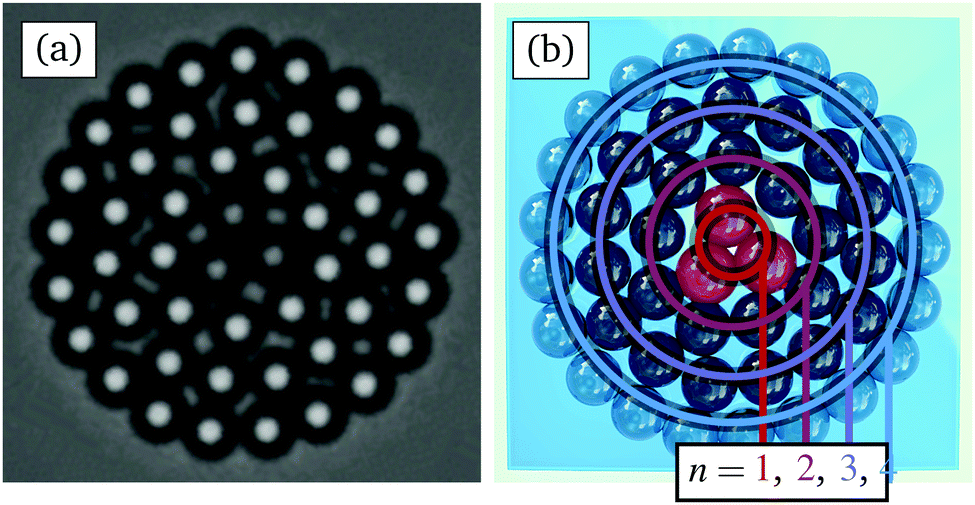 | ||
| Fig. 1 (a) Experimental and (b) schematic image of the considered system, consisting of a two dimensional cluster of confined microspheres. For clarity, we have marked in (b) the four rings n = 1, 2, 3, 4 with colored lines. The outer ring of particles (n = 4) is trapped by optical tweezers, while the three paramagnetic particles, forming an inner triangle (n = 1) at the center, are actuated by a rotating magnetic field. | ||
Our optical tweezers setup consists of a 1064 nm laser (ManLight ML5-CW-P/TKS-OTS, operated at 3W) deflected by an Acousto Optic Device (AOD, AA Optoelectronics DTSXY-400-1064, driven by a radio frequency generator DDSPA2X-D431b-34 and two NI card cDAQ NI-9403) and focused from above by a microscope objective (Nikon 40× CFI APO). The sample is observed from below through a second objective (Nikon 40× Plan Fluor) which is projected to a CMOS camera (Ximea MQ003MG-CM). The AOD moves the trap to a new position every 0.5 ms. This speed is such that, for a typical ring of 21 particles, each trap is visited every 10 ms. This time scale is much smaller than the characteristic Brownian time of the particles (τ ∼ 40 s), corresponding to the translational diffusion. Thus, the potential generated by this time shared optical trap can be considered quasi static and effectively acts simultaneously as 21 individual traps for each particle, respectively. We use a custom built LabVIEW program to observe and to manipulate the particles through a graphical interface, and to assemble the cluster one by one. The LabVIEW code can be accessed via github.41
The sample is placed inside a set of five coils which allow us to apply a magnetic field in any direction. The coils are driven by a NI card (cDAQ NI-9269), and the signal is amplified with three power operational amplifiers (KEPCO BOP 20-10). The magnetic field is also controlled by a LabVIEW program, which allows us to automate the data acquisition. Particle positions are extracted using the trackpy42 implementation of the Crocker–Grier algorithm.43
3 Numerical calculations
3.1 Model
As shown in Fig. 1, we consider a suspension containing a two-dimensional disk-like colloidal cluster. It consists of 45 polystyrene and 3 paramagnetic particles, whose diameter are d = 4 μm and dM = 1.125d, respectively. Similar to the experimental setup, the colloids inside the cluster are confined by an outer ring of polystyrene particles, and each particle is subjected to a harmonic trap potential, which is given by | (1) |
The inner paramagnetic particles are driven by a rotating magnetic field B(t) = B0[cos(ωM)ex + sin(ωM)ey], where B0 is the strength of the magnetic field, ωM = 125.7 rad s−1 is the angular frequency employed in the experiments, and ex as well as ey are the unit vectors in x and y direction. This magnetic field induces a finite internal relaxation time of the particle magnetization,33 which can be modeled via a simple relaxation equation ∂μi(t)/∂t = τrel−1[μi − VχB(t)], where μi is the dipole moment, V = πd3/6 the volume, and χ = 1.4 the susceptibility of the paramagnetic particle i, whereas τrel = 0.00015τB is the relaxation time scale for the induced magnetic dipole and τB = d2/D0 = 40 s is the Brownian time of a particle of diameter d that is defined by D0 the diffusion constant. As a result, the paramagnetic particles are subject to a net magnetic torque ![[scr T, script letter T]](https://www.rsc.org/images/entities/char_e533.gif) i, defined via
i, defined via
 | (2) |
The steric particle–particle interaction between the polystyrene as well as paramagnetic particles is modeled via a generic Yukawa-like potential, given by
 | (3) |
![[thin space (1/6-em)]](https://www.rsc.org/images/entities/char_2009.gif) exp(κd)kBT is the strength of the particle interactions, κ = 40d−1 is the inverse Debye screening length, d is the mean diameter d = (di + dj)/2 of the interacting particles, rij is the distance between the interacting particles.
exp(κd)kBT is the strength of the particle interactions, κ = 40d−1 is the inverse Debye screening length, d is the mean diameter d = (di + dj)/2 of the interacting particles, rij is the distance between the interacting particles.
The interaction between the induced dipole moments is modeled via a time-averaged dipole–dipole interaction exerted between the rotating paramagnetic particles, given by
 | (4) |
![[small mu, Greek, tilde]](https://www.rsc.org/images/entities/i_char_e0e0.gif) 0 is the magnetic constant and B0,DD = 0.117 [mT] is a constant magnetic field strength. The latter is set such that the radius of the inner ring consisting of paramagnetic particles is approximately constant and equal to that measured in experiments Rin = 0.625d.
0 is the magnetic constant and B0,DD = 0.117 [mT] is a constant magnetic field strength. The latter is set such that the radius of the inner ring consisting of paramagnetic particles is approximately constant and equal to that measured in experiments Rin = 0.625d.
3.2 Simulation details
We perform (overdamped) Stokesian dynamics simulations to investigate the non-equilibrium dynamics of the colloidal particles actuated by the magnetic torque. The equation of motions read | (5) |
j is the magnetic torque acting on the paramagnetic particles. In addition, the colloids are subject to random displacements ∂W with zero mean and variance 2D0∂t.
In our framework, the hydrodynamic interactions between the particles are accounted for via the translation–translation  as well as the translation–rotation mobility tensors
  , see eqn (24) and (28) given in Appendix A. In particular, we use expressions that include the finite extent of the colloidal particles on the Rotne–Prager level as well as the presence of the plane boundary represented by the bottom of the specimen,‡ see Appendix A for details. Note that, compared to ref. 12, we here employ new, refined expressions for the
  in order to treat the bidispersity of the considered colloidal suspension accurately. As a consequence, we have identified a new set of parameters for the particle interactions (εY and κ) via a parameter scan that aims to match the mean dynamics from simulations and experiments. To this end, we consider the limiting case of a vanishing magnetic field B0 = 0 and rotate the outer ring with constant angular velocity Φi = ωRt + 2πi/N4, a situation which was discussed in ref. 12 as well as11 for a monodisperse cluster. For this limiting case, we compute and compare the mean angular velocities per ring as a benchmark to identify an appropriate set of parameters.
Finally, note that the rotational degrees of freedom are modeled only implicitly by the translation–rotation mobility tensors, see eqn (24), and the magnetic torque, see eqn (2). Here, we have assumed that the particles are not in direct contact as they are separated by a thin layer of solvent. Thus, the particles are able to rotate freely, following the hydrodynamic flow. We also note that an explicit modelling of the magnetic degrees of freedom (i.e., the dipole orientations) of the three inner particles is not necessary since these particle are paramagnetic and, thus, their dipole orientations are governed by the external field (and do not fluctuate). The impact of the field is then solely described by the torque given in eqn (2).
4 Azimuthal dynamics
In our previous study,12 we have focused on the particle dynamics as well as the corresponding rheological response at rather strong magnetic torques B02. We now concentrate on the dynamics that are observed for much smaller B02. Consequently, we limit ourselves to a much smaller range of field strengths B0 < 1 [mT].To characterize the steady state dynamics, we calculate the mean angular velocity per ring
 | (6) |
| ri(t) = r[cos(φi)ex + sin(φi)ey]. | (7) |
4.1 Experiments
In the experiments, the mean angular velocity is computed from Nloops = 60 subsequent sweeps. Starting from equilibrium, each sweep proceeds by slowly increasing the magnetic field, and thus the torque, in discrete steps ΔB02 = 0.05 mT2 up to a maximum of B02 = 1 mT2, followed by another sweep where the magnetic torque is decreased at the same rate to equilibrium. The total duration of each sweep is 5τB ≈ 200 s. Finally, averaging over all realizations, we find the mean angular velocity per ring, which is plotted in Fig. 2(a). Here, we average over both, forward and backward, sweeps as we find that the mean angular velocities from the two sweeps are approximately the same. This indicates that, at each step, the system managed to relax to the steady state and the sweeps were performed sufficiently slowly.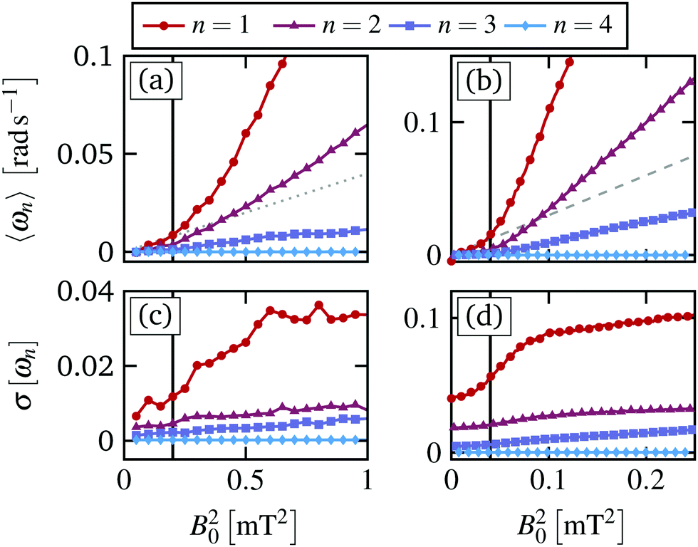 | ||
| Fig. 2 (a) Experimental and (b) simulation results for the ensemble averaged mean angular velocity per ring n = 1,…,4 as a function of the magnetic torque ∝ B02. The gray dotted line in (a) indicates the initial slope of the angular velocity of the paramagnetic particles, 0.04B02, in experiments, and the dashed line in (b) indicates the corresponding slope 0.3B02 in simulations. The standard deviations of the angular velocities in (a) and (b) are plotted in (c) and (d), respectively. | ||
Starting from equilibrium and applying the magnetic field to the paramagnetic particles, the mean angular velocity of the inner ring first increases as a linear function of the torque, i.e. ω1 ∝ B02. The initial slope is emphasized by the gray dotted line in Fig. 2(a). At a critical magnetic torque B0,c2 = 0.2 [mT2] the inner ring speeds up, yielding another linear increase with larger slope. Henceforth, we refer to this behavior as a “depinning transition” between two states with strongly different dependency of ωn on the magnetic torque. While overall slower, the second (ω2) and the third ring (ω3) both show the same behavior, including the depinning transition at the same critical magnetic torque.§ Obviously, the outer ring remains static since the composing particles are trapped by the laser trap, for all B02. Note that a linear relation between the angular velocity and the magnetic torque is already found for a free rotating triplet of paramagnetic particles, which forms the inner ring, as discussed in the ESI of ref. 12. However, the actual slope and magnitude of the resulting angular velocities per ring strongly depend on the interactions between them.
Importantly, in contrast to ref. 12, we find that for B02 < Bc,0 we do not observe a fully locked state, i.e. a state where ωn vanishes completely and the particles remain static on average. The reason is that in our previous work the dynamics at small B02 were not sufficiently resolved to distinguish between a static state and the very small mean angular velocity, as shown in Fig. 2(a) and (b). However, for B02 < B0,c2, the inner rings do not perform a regular rotation either. Instead, the slow mean angular motion results from a series of slip events, where the inner rings “depin” from the static outer ring for a brief moment before locking again. This behavior is reminiscent of the behavior near the depinning transition in incommensurate driven monolayers at finite temperature.44 For the latter, one also observes a small net particle flux for subcritical driving forces, due to rare particle jumps that are induced by the thermal noise. The slip events in the present system are discussed in more detail in Section 5.
The depinning transition at Bc,02 is also reflected by the standard deviation of the mean angular velocities
 | (8) |
4.2 Simulations
In simulations, we mimic the procedure employed in the experiments performing up to Nens = 10000 forward and backward sweeps with ΔB02 = 0.0025 mT2 up to a maximum of B02 = 0.25 mT2 and a total duration of 10τB per sweep. Similar to the experiments, we find a transition at B0,c2 between two dynamical states, both characterized by a linear increase of the mean angular velocity. In simulations the initial slope is indicated by a gray dashed line, see Fig. 2(b). We find that the critical magnetic torque in simulations, B0,c2 = 0.04 mT2, is smaller than in experiments, and this difference in the applied magnetic field was also reported previously.12 At the same time, for B02 > B0,c2, the mean angular velocity of the inner three rings is larger than that of the experiments. We attribute these deviations to the limitations of our approximations for the hydrodynamic interactions as well as the fact that we neglect the surface friction between the rotating colloidal particles. The latter would require to explicitly take into account the rotational degrees of freedom, which currently are considered only implicitly.
In addition to the mean values, the standard deviation of the mean angular velocity σ[ωn], plotted in Fig. 2(d), is in good agreement with that of the experiments, showing a marked increase at the critical magnetic torque B0,c2. However, in simulations the mean angular velocity fluctuations are much stronger than in experiments.
To further analyze the depinning transition at B0,c2, we compute the distribution P(ωn) of the time-averaged angular velocities of the individual realizations,¶ which are plotted in Fig. 3(a) and (b) for the inner ring from experiments and simulations, respectively. Again, we find that the width of the distributions, i.e. the standard deviation, displays a sudden increase at B0,c2, as already shown in Fig. 2(c) and (d) for experiments and simulations, respectively. The large width of the distributions reflects the fact that we find realizations, which seem to be momentarily locked with ωn ≈ 0 even for B02 > B0,c2. Overall, the distributions for the three inner rings n = 1, 2, 3 are non-Gaussian, displaying positive skewness m3[ωn] > 0 as well as large kurtosis m4[ωn] > 3 for most B02. Here we have used the standard definition for the skewness
 | (9) |
 | (10) |
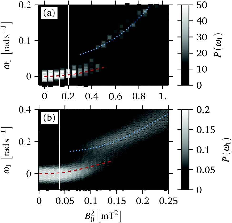 | ||
| Fig. 3 (a) Experimental and (b) simulation results for the evolution of the distribution of the mean angular velocity of the inner ring ω1 during the magnetic field sweeps. The dashed red and dotted blue line indicate the evolution of the two peaks of P(ω1). The distributions correspond to the mean values and the standard deviations, which are plotted in Fig. 2(a–d). | ||
Further, we find that the distribution of the inner ring, P(ω1), display the most complex behavior. In particular, we observe a range B02 = 0.06–0.14 [mT2] where P(ω1) becomes bimodal, see the red dashed and blue dotted line in Fig. 3(a). In contrast, P(ω2) and P(ω3) remain unimodal for all B02, see Fig. S2 in the ESI.† In the bimodal regime some realizations are essentially “locked”, i.e. ω1 ≈ 0, whereas other realizations display a rotation with finite angular velocity, corresponding to a “running” state. With increasing B02 the number of realizations in an approximately locked state (red dashed) decreases and the number of realizations in the “running” state (blue dotted) increases continuously. We note again that the distributions P(ωn) from the forward and the backward sweeps are approximately identical, indicating that the steady state for these magnetic torques is truly bistable.
In the experiments, we find very good agreement with the simulations results, as shown in Fig. 3(a). That is, we also find a range B02 = 0.3–0.6 [mT2] where P(ω1) becomes bimodal. In this field range, we find realizations either in a locked or in a running state, where the number of realizations in a running state increases with increasing magnetic torque. Thus, the agreement between simulation and experiments is not limited to the mean values but extends to the fluctuations of ωn.
To understand this bistability, recall the fact that each ωn is computed from a sweep lasting Δt = 0.1τB in simulations and Δt = 0.25τB in experiments for each magnetic torque. Thus, P(ω1) shows that the rings of the single realization are either momentarily (t > Δt) locked or running, corresponding to the two states respectively. In fact, we do not find a single realization that remains in either the locked nor the running state for all times. Since each realization remains in the locked or running state only for a finite amount of time, this bimodal distribution may collapse for very long sweeps, i.e. Δt ≫ τB. The time at which the two states can not be distinguished is connected to the waiting time, that we discuss in Section 5.2. Note that the critical torque does not depend significantly on the sweep duration. As a result, the transient bistability is intimately connected to the temporal heterogeneity of the microscopic dynamics, which we discuss below.
5 Microscopic (angular) dynamics
The average azimuthal dynamics, that we have discussed in Section 4, is intimately related to the dynamics of the individual colloids. In this section, we analyze the latter by means of the particle trajectories, the waiting- and jump time distributions, as well as the mean squared displacement. This analysis requires long trajectories (t > 10τB) for each magnetic torque for a large number of realizations, which are difficult to realize in experiments due to the stability of the colloidal particles. As a results, in this section we mostly used simulation results.5.1 Trajectories
In Fig. 4(a)–(d), we have plotted simulation results for trajectories of the single particles. At very small magnetic torques B02 = 0.0025 [mT2], see Fig. 4(a), we find long periods where the particles are locked to their respective angular position (i.e., Δφi(t) = φi(t) − φi(0) = const.), which are disrupted by sudden and very fast slips. At the end of a slip the particle then resides again at an approximately constant Δφi(t) for relatively long periods. At the magnetic torques considered, these slips are likely to be triggered by thermal fluctuations, allowing also for “backward” slips where particles jump to smaller values of Δφi. These slips lead to a very small, but finite, mean angular velocity, as shown in Fig. 2.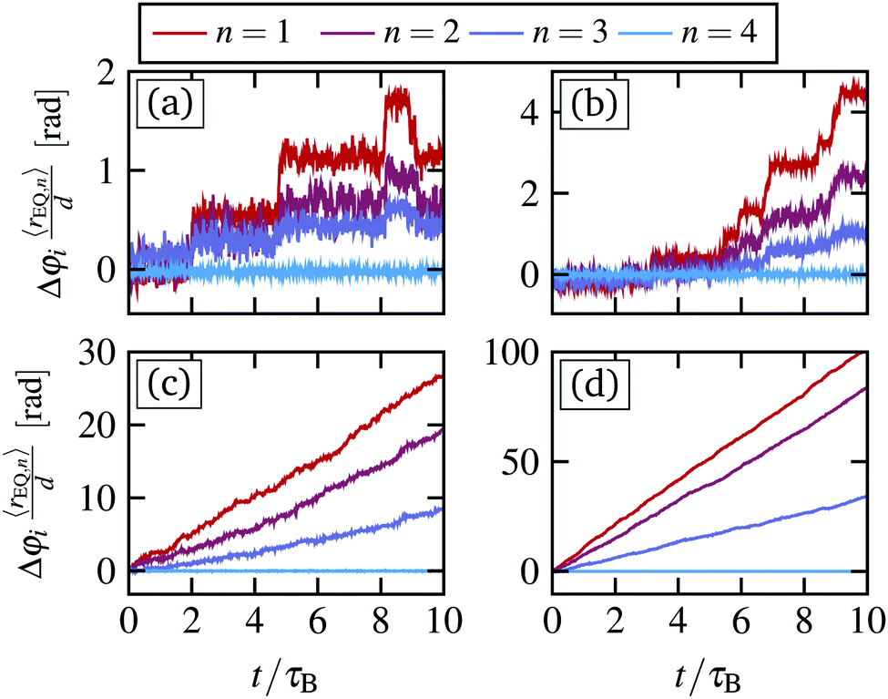 | ||
| Fig. 4 (a)–(d) Simulation results for the rescaled angular displacement trajectories for one arbitrary particle belonging to the n = 1, 2, 3, 4 ring for four different magnetic torques B02 = 0.0025, 0.04, 0.1, 0.25 [mT2], which are below, at, and above the critical value Bc,02 = 0.04 [mT2]. To improve clarity, we have multiplied the angular displacement for each particle by the mean radius of their ring at equilibrium (rEQ,n). The trajectories therefore represent approximately the azimuthal displacement of the particle. | ||
Increasing the magnetic torque, the frequency of the slips increases and the angular displacement during a single slip becomes larger. This is clearly reflected in the trajectories at B02 = Bc,02 = 0.04 [mT2], see Fig. 4(b). Here, we find again long periods, where the particles are locked, and a series of very fast slips. However, the slips become more directed into positive angular direction Δφi > 0 and the time between these slips becomes shorter.
For supercritical magnetic torques, e.g. B02 = 0.1 [mT2], we find that the particle trajectories are mostly characterized by a continuous motion along azimuthal direction, see Fig. 4(c). However, there are short periods where the inner rings lock and Δφi remains approximately constant. While this transient locking is most pronounced for the inner ring (n = 1), we observe similar behavior in the other rings n = 2, 3. The transient locked periods reflect, on the trajectory level, the bistable region shown in Fig. 3(a). In particular, realizations inside these locked periods correspond to the low mobility states, i.e. red dashed line in Fig. 3(a).
For large magnetic torques, i.e. B02 = 0.25 [mT2], all the inner rings display a continuous motion in azimuthal direction, which is reflected by a continuous increase of Δφi, as shown in Fig. 4(d). Thus, the system has entered a running state, which is consistent with our observations for the mean angular velocities of the inner rings Fig. 2(b).
In Fig. 5(a) and (d), we compare short trajectories from experiments and simulations, respectively. In experiments, the available particle trajectories are too short (t = 0.25τB) to see the rare jumps for B0 < B0,c, However, for B0 > B0,c we find good agreement with particles showing short periods of transient locking as seen in simulations, see Fig. 5(b), (c) and (e), (f).
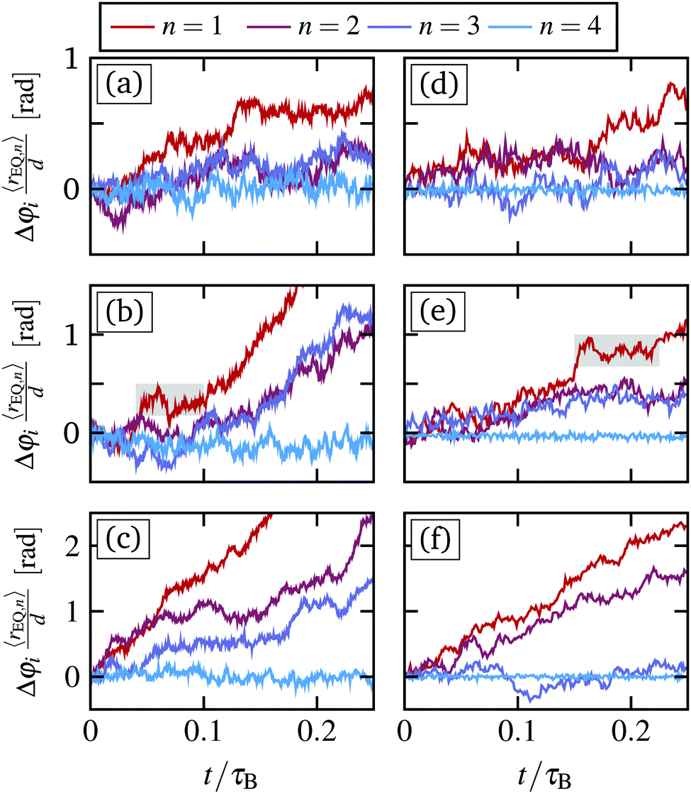 | ||
| Fig. 5 (a)–(c) Experimental results for the short time trajectories for one arbitrary particle of each ring for three different magnetic torques B02 = 0.2, 0.4, 1 [mT2]. (d)–(f) Trajectories from simulations for comparable magnetic torques B02 = 0.04, 0.1, 0.25 [mT2]. Thus, (a) and (d) correspond to the trajectories at B0,c. In (b) and (e), we have emphasized regions were the particles are temporarily locked in experiments and simulations, respectively. | ||
5.2 Waiting time distribution
To quantify the frequency of the slip events, that we have discussed for Fig. 4(a)–(d), as well as their duration, we have computed the waiting- and jumping time distribution employing the definition from ref. 45. We define, for each particle, a minimum angular position by the angle centered between the two neighboring particles of the outer adjacent ring. A forward jump is initiated when a particle passes this minimum angular position along the positive direction. The jump concludes after the jumping time tJ once the particle passes the minimum angular position of the next neighbors. The time in between jumps is the waiting time tW. For a sketch see Fig. S4 in the ESI.†Jumping- and waiting times of backward jumps can be defined accordingly. We note that the backward jumps are observed only for subcritical magnetic torques and become increasingly rare close to the critical magnetic torque. While the presence of backward jumps marks the difference between the sub- and supercritical state we will focus on the forward jump statistics, in the following.
We have plotted the waiting time- and jumping time distributions for forward jumps for B02 = 0.0025, 0.04, 0.1, 0.25 [mT2] in Fig. 6(a–d) and (e–h), respectively.
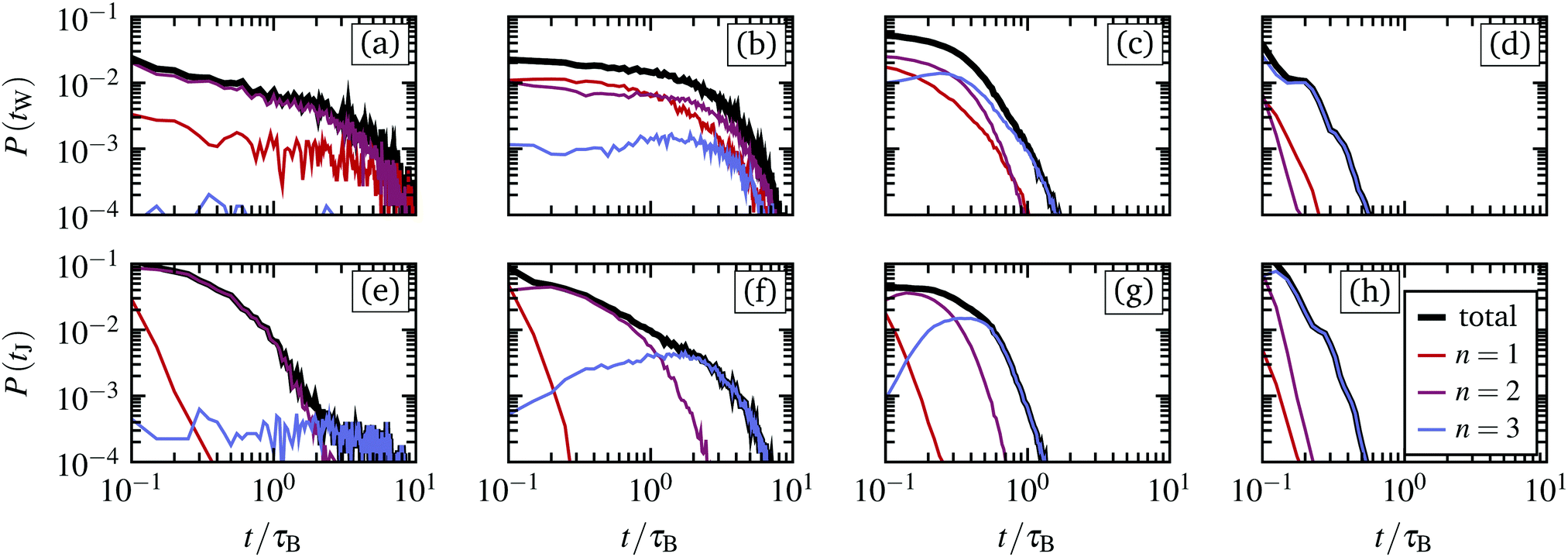 | ||
| Fig. 6 Simulation results for the waiting times (a–d) and jumping times (e–h) corresponding to the trajectories as shown in Fig. 4(a)–(d), for magnetic torques B02= 0.0025, 0.04, 0.1, 0.25 [mT2], respectively. The total distribution (black) is decomposed into that of the individual rings n = 1, 2, 3. | ||
Starting with the distribution P(tW), we find that tW is approximately exponentially distributed for the first and second ring (n = 1, 2). In particular, we find a high probability for short waiting times tW < τB, that are not apparent in the trajectories, see Fig. 4(a) and (b). These short waiting times stem from particles jumping more than one interstice at once, which in our definition is interpreted as multiple subsequent jumps following each other, yielding very small waiting times between them. In fact, especially for the rings with n = 1, 2, jumps over multiple minima seem to be very common. With increasing magnetic torque, the waiting times become continuously shorter, which is consistent with the observations from the single particle trajectories, see Fig. 4. In particular, for very large magnetic torques the waiting times tW < τB, such that the motion appears continuous in the presence of thermal fluctuations.
Interestingly, the third ring (n = 3) displays a different behavior, which we attribute to the fact that the corresponding particles jump only one interstice at a time. For this ring, we observe in Fig. 4(b)–(d) distributions with pronounced maxima. This maximum clearly indicates a characteristic time scale for the slips of the third ring, which again becomes shorter with increasing magnetic torque. Comparing all the rings, we see that the typical waiting times in the range B02 ≤ B0,c2 are approximately equal, indicating that the slip events are synchronized between the different rings. In contrast, for larger magnetic torques, the waiting times become longer with increasing radial distance from the center.
For the jumping times, a dependency on the ring is observed for all magnetic torques. Specifically, the first ring displays the smallest jumping times and the third ring the longest, see Fig. 6(c and d). This difference is most prominent for B02 ≤ B0,c2, where the typical duration of the jumps can vary by an order of magnitude. Overall, most of the jumping time distributions display a maximum, which again yields a characteristic time scale of the microscopic dynamics.
5.3 Mean squared angular displacement
A further measure of the microscopic motion, is the mean squared angular displacement (MSD), which is calculated from the individual trajectories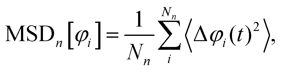 | (11) |
 | (12) |
 | ||
| Fig. 7 (a) Simulation results for the mean squared angular displacement of the particles inside the inner ring n = 1 for various magnetic torques from simulations. (b) Mean squared displacement relative to the center of mass motion of the particles inside the inner ring n = 1. The gray dashed line signifies a linear increase, whereas the gray solid line represents a quadratic increase. | ||
In both cases, for very short times t < 10−3τB, we find an initial linear increase of MSD[φi] ∝ t, corresponding to diffusive motion of the colloidal particles inside their respective “cages” formed by the surrounding colloidal particles. At intermediate times t ≈ 0.01τB, the mean squared angular displacement response becomes strongly dependent on B02. Considering first Fig. 7(a), we see that for small magnetic torques B02 < Bc,02, the mean squared displacement displays a plateau up to t ≈ 0.1τB. For longer times, the MSD switches to ballistic motion, i.e. MSD[φi] ∝ t2. This corresponds to the directed angular motion that we have already discussed in Fig. 2(b).
Subtracting the center of mass motion, as plotted in Fig. 7(b), we see a similar transition of  . However,
  transitions for long time again into a linear time dependency, corresponding to diffusive motion relative to the center of mass motion. The corresponding diffusion constants increases continuously with the magnetic torque B02.
Interestingly, the time range where MSD[φi] displays a plateau corresponds to the typical time in which the particles remain locked between the slips, as shown in Fig. 4(a) and (b). With increasing magnetic torque, the width of the plateau decreases, corresponding to the decrease of the typical waiting times at the different B02, shown in Fig. 6(a–d). We note that such a plateau of the mean squared displacement is often observed in sheared colloidal glasses39 and other strongly correlated driven fluids.46,47 For the former, one can relate the stress overshoots and the sub-diffusive domain with the breakage of the individual particle cages that are comprised of its neighboring particles.39 In fact, we do also observe stress overshoots as discussed below, thus we think that the same reasoning applies to our sheared colloidal system. Here, the cages are composed of the particles from the neighboring rings as well as the direct neighbors inside the same ring.
6 Stress tensor
To further characterize the observed dynamical behavior, we now discuss various mechanical properties. In particular, following our previous study, we calculate the components of the configurational stress tensor in polar coordinates, | (13) |
6.1 Shear stress
We start by considering the shear stress,![[scr S, script letter S]](https://www.rsc.org/images/entities/char_e532.gif) rφ, which is plotted in Fig. 8(a). Starting from equilibrium, the shear stress increases approximately linearly as a function of the magnetic torque up to B0,c2, reflecting Newtonian behavior. For supercritical magnetic torques B02 > B0,c2, the shear stress then crosses over to another linear increase with smaller slope. Note that the slope of the shear stress can be identified as the shear viscosity of the system;48 thus its decrease reflects a shear-thinning behavior.
rφ, which is plotted in Fig. 8(a). Starting from equilibrium, the shear stress increases approximately linearly as a function of the magnetic torque up to B0,c2, reflecting Newtonian behavior. For supercritical magnetic torques B02 > B0,c2, the shear stress then crosses over to another linear increase with smaller slope. Note that the slope of the shear stress can be identified as the shear viscosity of the system;48 thus its decrease reflects a shear-thinning behavior.
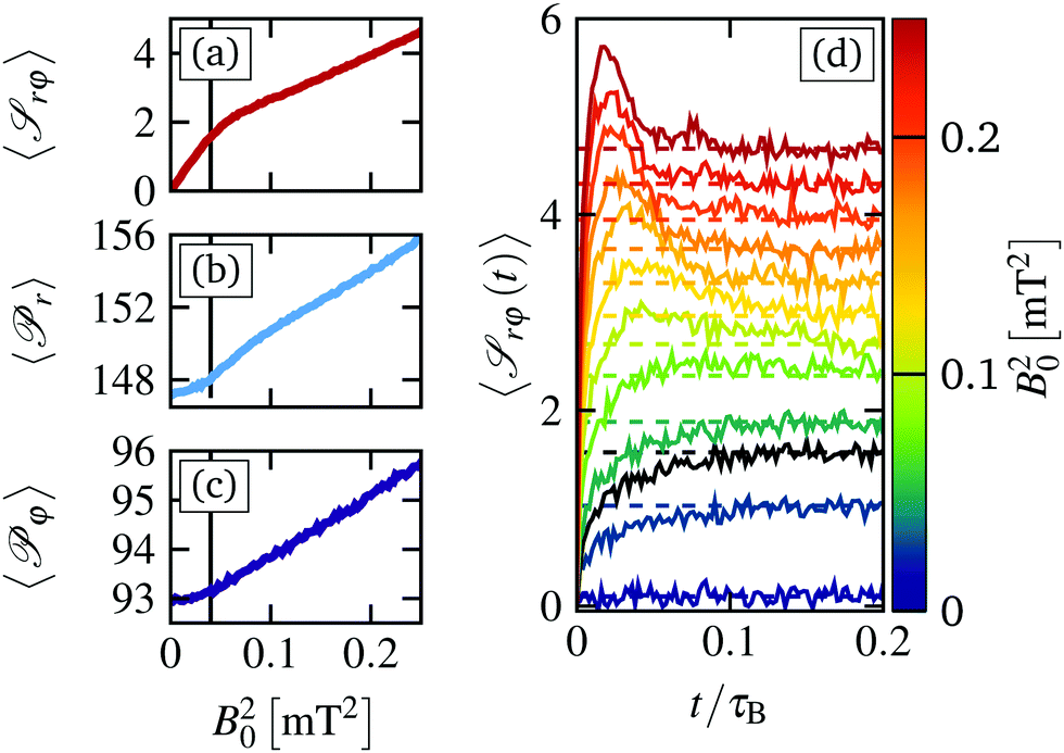 | ||
Fig. 8 (a) Simulation results for the mean shear stress rφ, (b) mean radial pressure ![[scr P, script letter P]](https://www.rsc.org/images/entities/char_e52f.gif) r, (c) mean azimuthal pressure φ as a function of the magnetic torque B02. The black line indicates the critical magnetic torque at B0,c = 0.04 [mT2]. (d) Shear stress relaxation curves rφ(t) for various magnetic torques as indicated by the color. The black line corresponds to the stress relaxation at B0,c. The dashed lines correspond to the steady state shear stress plotted in (a). r, (c) mean azimuthal pressure φ as a function of the magnetic torque B02. The black line indicates the critical magnetic torque at B0,c = 0.04 [mT2]. (d) Shear stress relaxation curves rφ(t) for various magnetic torques as indicated by the color. The black line corresponds to the stress relaxation at B0,c. The dashed lines correspond to the steady state shear stress plotted in (a). | ||
Similar to the fluctuations of the angular velocity, shown in Fig. 2(c and d), the shear stress displays fluctuations whose magnitude clearly reflect the depinning transition at B0,c2. In particular, we find a strong increase of the standard deviation as well as an increase of the skewness, see Fig. S3 in the ESI.† This effect implies that the stress fluctuations are increasingly biased towards large values, which can be attributed to the increasing number of slip events, during which large stresses are exerted.
We have also investigated the time-dependence of the shear stress, see Fig. 8(d). For various values of B02 considered, we start in equilibrium and switch on the magnetic field at t = 0 for up to Nens = 10000 realizations. The data reveal, first, that the relaxation towards the steady state values occurs in rather short times t < 0.2τB. This is an indirect confirmation that the angular velocity sweeps described in Section 4.2 are performed sufficiently slowly such that the internal stresses can relax. Analyzing further the curves rφ(t) in Fig. 8(d), we find a monotonous increase of the shear stress within the range of B02 < B0,c2, that is the steady state shear stress is approached from below. In contrast, for B02 > B0,c2, we find a non-monotonic behavior characterized by a pronounced stress “overshoot”. This overshoot dynamics is characteristic for glassy (and other strongly correlated) systems. It is related to the breaking of the particles cages, consisting of neighboring particles,39 and is connected to a plateau region in the mean squared displacement, see Section 5.3.
6.2 Pressure
We now turn to the radial pressure,r = −rr, and the azimuthal pressure, φ = −φφ, which correspond to the diagonal components of the stress tensor and are plotted in Fig. 8(b and c), respectively. In general, both the radial as well as the azimuthal pressure show similar behavior. We find an approximately constant value for subcritical magnetic torques B02 < B0,c2, which crosses over to a continuous increase with torque for B02 > B0,c2. Overall, the radial pressure is larger and grows faster than the azimuthal pressure, consistent with our results from previous studies.12
The resulting increase of the radial pressure is accompanied by radial deformations of all rings from its equilibrium radius, which we have plotted in Fig. 9(a) and (b) for experiments and simulations, respectively. In general, we observe a strong expansion of the system at the critical magnetic torque, where the particles start to slide past each other. This leads to particles stacking up in radial direction, pushing the outer ring outwards against the (soft) harmonic traps, yielding eventually an increase of radial pressure. Interestingly, in contrast to the three outer rings, the inner ring (n = 1) displays a compression for B02 > B0,c2. These effects are seen in both, simulations and experiments. However, the compression of the inner ring is much more pronounced in experiments, as shown in Fig. 9(a). We attribute this to the fact that the strength of the induced dipole–dipole interaction is proportional to the magnetic torque, see eqn (4). This results in a stronger attraction for larger magnetic torques. As a result, the inner ring in the experimental system compresses already for B02 < B0,c2, which also leads to a small initial compression of the second ring. In simulations, we keep the strength of the mean dipole–dipole interactions eqn (4) constant to prevent a pronounced compression, which leads to a significant speedup of the inner ring that is not observed in experiments.12 The observed compression of the inner ring n = 1 is due to the inherent softness of the particle interactions: the outer particles push the inner particles inward. Irrespective of these subtle differences between experiment and model system, the overall agreement is quite satisfactory.
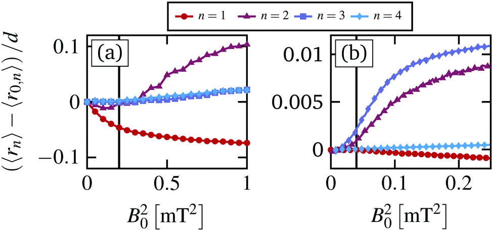 | ||
| Fig. 9 (a) Experimental and (b) simulation results for the mean radius relative to the equilibrium radius for all rings (n = 1,…,4). | ||
7 Thermodynamical consequences
In this last section we briefly discuss some aspects of the observed dynamical behavior from the perspective of stochastic thermodynamics. Here, we focus on the stochastic energetics, i.e. the work and heat. To this end, we employ generalized expressions for the stochastic work- and heat rate given in ref. 49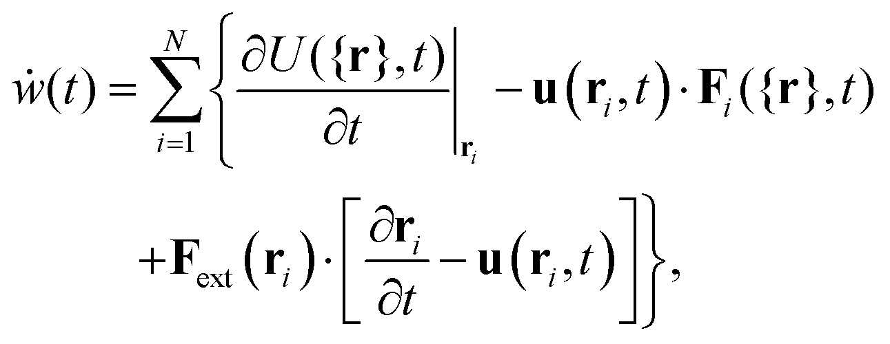 | (14) |
 | (15) |
For the sheared colloidal system with a static outer ring, ∂U/∂t = 0 and Fext = 0, we identify only one possible source of work. This is the work done by the rotating magnetic field, which drives the rotation of the paramagnetic particles. Within our model, we do not account for the rotational degrees of freedom of the colloidal particles explicitly. Rather, the rotating magnetic field enters through the mean solvent flow exerted by the paramagnetic particles. Therefore, we set the external flow in eqn (14) and (15) to
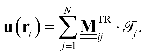 | (16) |
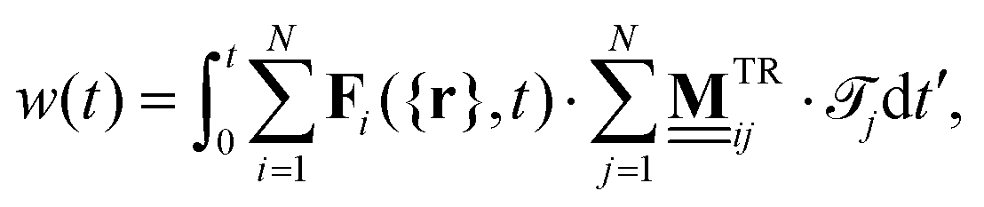 | (17) |
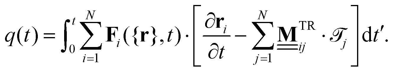 | (18) |
7.1 Magnetic torque dependency
In our numerical investigation, starting from the steady states obtained from the magnetic torque sweeps, plotted in Fig. 2(b), we compute work – w(t) and heat trajectories q(t) for t = 0.1τB for the Nens = 10000 systems to study the short-time behavior. The resulting mean work and heat at t = 0.1τB, as well as the corresponding standard deviation, is plotted in Fig. 10.
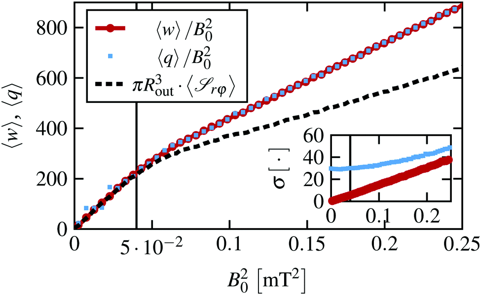 | ||
| Fig. 10 Simulation results for the mean work w (red circle) and heat q (blue square) for integration time t = 0.1τB rescaled by the magnetic torque B02. The rescaled mean shear stress is plotted for reference. The inset shows the standard deviation of the work and heat, respectively. | ||
Applying the magnetic torque B02, 〈w〉 displays a quadratic increase as a function of the torque B02. For supercritical magnetic torques, the work crosses over to another quadratic regime where 〈w〉 increases slower as a function of B02. That is, the depinning transition at B0,c2 is clearly reflected by the mean work as a function of B02. Interestingly, the same does not hold for the standard deviation of the work σ[w], plotted in the inset in Fig. 10, which displays a linear increase with constant slope for all considered B02. The corresponding distributions are approximately Gaussian, yielding m3[w] ≈ 0 and m4[w] ≈ 3 for all B02.
Turning now to the heat, we find that on average the heat and the work are the same for all considered magnetic torques, as expected in a steady state. However, the heat distributions display a finite width already in equilibrium, which remains approximately constant for subcritical magnetic torques B02 < B0,c2 and a subsequent linear increase for supercritical values B02 > B0,c2, as plotted in the bottom right inset in Fig. 10. In general, P(q) deviate from a Gaussian distribution, displaying a small positive skewness m3[q] ≈ 0.2 as well as a larger kurtosis m4[q] ≈ 4 for all B02.
In Fig. 10, we have plotted the mean work divided by the magnetic torque B02, which allows for an easy comparison with the shear stress. This comparison is motivated by our results for a planar slit pore system, where these two quantities are closely related.40 However, the same does not hold true for the sheared circular system, which deviates from the expected relation for B0 > B0,c.
7.2 Time dependency
As discussed in our earlier study of a planar slit pore system,40 the work and heat distributions are in general time dependent and the same behavior occurs here. Regarding the mean values, we find a linear increase in time for both the work and the heat, that is, 〈w(t)〉 ≈ 〈ẇ〉t and 〈q(t)〉 ≈ 〈![[q with combining dot above]](https://www.rsc.org/images/entities/i_char_0071_0307.gif) 〉t, and the functions are fully determined by their respective mean rates, as expected for a steady state. Turning now to the time evolution of the standard deviation, we find a power law behavior for the work σ[w(t)] ∝ t0.55 for all considered magnetic torques. Note that this is very close to
〉t, and the functions are fully determined by their respective mean rates, as expected for a steady state. Turning now to the time evolution of the standard deviation, we find a power law behavior for the work σ[w(t)] ∝ t0.55 for all considered magnetic torques. Note that this is very close to 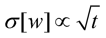 that one finds for a single particle in a translated harmonic trap, yielding
 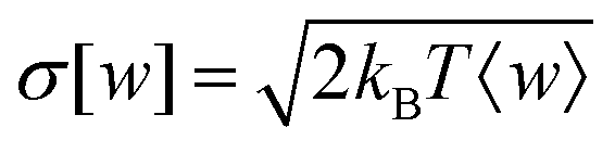 as follows directly from the integrated fluctuation theorem.50 In contrast, σ[q(t)] displays a more complex behavior, shown in Fig. 11, where the strength of the fluctuations saturate for intermediate times before transitioning to another power law behavior. This saturation leads to a plateau, whose width seems to be connected to the typical waiting time of the particles as well as the plateau of the MSD discussed in Fig. 7. However, a detailed investigation would require longer runs and better statistics.
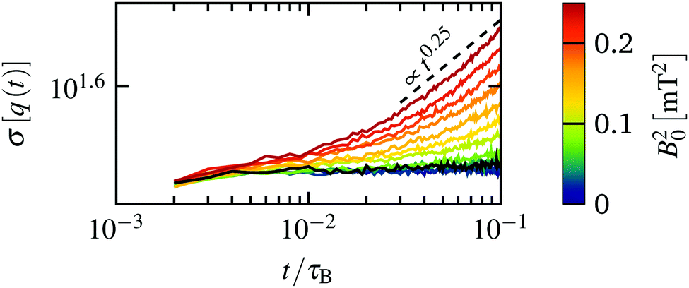 | ||
| Fig. 11 Simulation results for the standard deviation of the heat as a function of time t for various different magnetic torques. For reference, we have plotted a dashed line corresponding to f(t) ∝ t0.25. The standard deviation at the critical magnetic torque is plotted in black. | ||
Overall, we find that the depinning transition at B0,c2 is clearly reflected by the mean values of the work and heat, as well as the strength of the heat fluctuations σ[q] both with respect to the magnetic torque dependency and with respect to the time dependency. A deeper interpretation of these results remains, at present, difficult due to the absence of analytical results for these types of strongly correlated systems.
8 Conclusion
Performing video microscopy experiments as well as Stokesian dynamics simulations, we have studied a dense, bidisperse colloidal system confined to a two-dimensional, disk-like cluster that is actuated by an external magnetic field. The outer ring of particles are confined by harmonic traps and is kept static by time shared optical tweezers, whereas the inner ring, consisting of paramagnetic particles, is driven by a rotating magnetic field. Focusing on rather small magnetic torques, we find a pronounced depinning transition, that is reminiscent of that occurring in incommensurate driven monolayers at finite temperature.The dynamics at subcritical magnetic torques is characterized by a small, linear increase of the mean angular velocity per ring (with the applied torque), which stems from thermally activated slip-events. During the latter, the locking of the inner rings to the static outer ring is momentarily broken and the inner rings slide past each other. In this state, we observe both forward and backward slip events, where the probability of forward slips increases with increasing magnetic torque, yielding a net motion along the positive azimuthal direction. At a critical magnetic torque, the system enters a second steady state, where the probability to find backward slip-events vanishes. For this state, we find a bistability with respect to the mean angular velocity of the inner ring of the individual realizations. This bistability is clearly reflected by a bimodal distribution both in simulations and experiments.
We can understand the bimodal distributions by analyzing the particle trajectories, from which we compute the waiting times between the slips as well as the jump times, corresponding to the duration of a slip. For magnetic torques in the bistable region, the typical waiting time is of the order of the duration of the employed time average. Thus, some realizations are momentarily locked, whereas others have performed a slip, corresponding to the slow and fast state of the bistability, respectively. One interesting observation is that, for the first steady state, the typical waiting times of the different rings are approximately equal. In contrast, for the second steady state the typical waiting time increases with the radial distance from the center. This observation holds true for the jump times for all magnetic torques considered.
These typical waiting times are also reflected by the time-dependence of the mean squared displacement, which displays a pronounced plateau at intermediate times. The corresponding range of times decreases with increasing the magnetic torque. Such a sub-diffusive region is very common in strongly correlated sheared systems, such as colloidal glasses and dense liquid crystalline mixtures. It is accompanied by an overshoot of the shear stress relaxation curves, which we also find for supercritical magnetic torques. Both phenomena are connected to the breaking of particle cages, i.e. the plastic deformations during the slip events. Overall, by monitoring the stress components, we find a pronounced shear thinning behavior at the critical magnetic torque, which is accompanied by a marked increase of the azimuthal- and radial pressure. The latter corresponds to a radial expansion of the outer rings, which are observed both in simulation and experiments, as well as an compression of the inner ring.
Finally, we have briefly discussed the consequences of the depinning transition on two important stochastic thermodynamics quantities, i.e. the work and heat. We find that the depinning transition is reflected by the mean work and heat as function of torque. Moreover, we find signatures in the magnitude of the heat fluctuations as function of torque as well as in dependence the of integration time. Interestingly, we did not observe a direct correspondence between the work rate and the shear stress, as we have reported for a planar slit pore system.40
Overall, we find a very good agreement between numerical simulations and experiments not only with respect to the mean values but also the fluctuations of the mean angular velocity as well as the azimuthal- and radial displacements. One open question is the importance of the magnetic torque dependency of the dipole–dipole interactions exerted between the paramagnetic particles. Another interesting avenue is to analyze, in more detail, the plastic events during slips and their time- and space correlations. Here, one goal is to predict the emergence of slips. Finally, in the future, we aim to develop a deeper understanding of the stochastic thermodynamics in these strongly correlated systems. One major challenge is that many exact results from stochastic thermodynamics make predictions for the entropy production, whose calculation is not trivial. Research in this direction is in progress.
Conflicts of interest
There are no conflicts to declare.Appendix
A Hydrodynamic Interactions
The hydrodynamic interactions in our Stokesian dynamics simulations are modeled via the two mobility tensors and
and  that encode the hydrodynamic flow acting on particle i that is exerted from the translation and rotation of particle j, respectively. The setup we have in mind consists of two spherical particles with different diameters close to a plane boundary located at zW = 0, as sketched in Fig. 12.
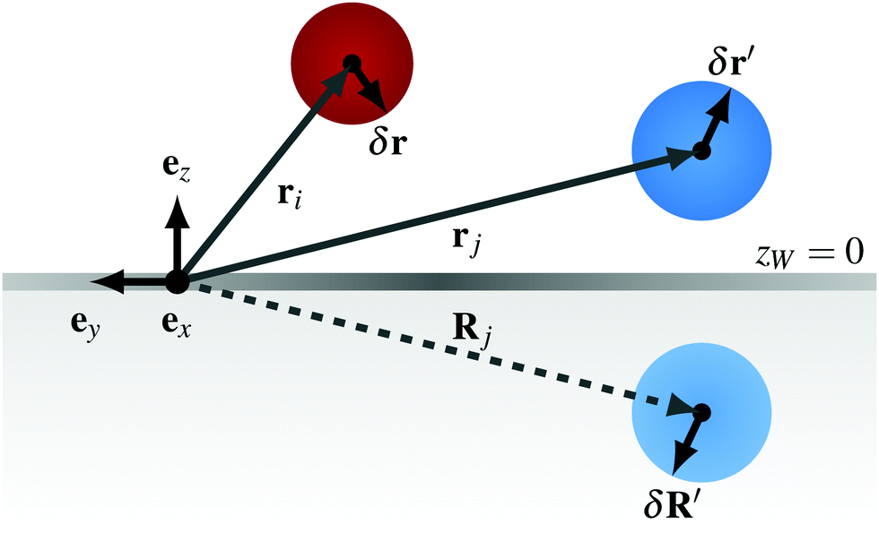 | ||
| Fig. 12 Sketch of the considered setup, with position ri, rj of particle i and j as well as the image Rj of particle j with respect to a plane boundary condition at zW = 0. | ||
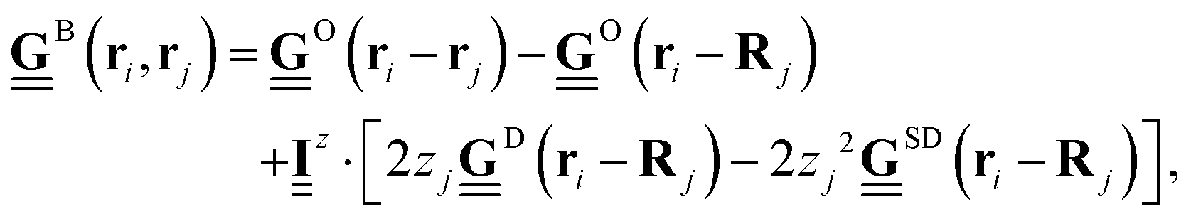
In the present study, we derive appropriate mobility tensors starting with the Blake solution51
 | (19) |
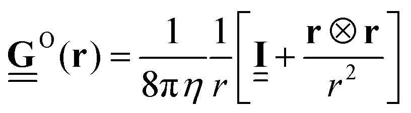 is the Oseen tensor between the two point particles at position ri and rj, whereas the remaining terms represent the corrections from the plane boundary condition. Further, Rj = rj − 2zjez is the position of the image of particle j,
 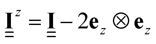 is a unit matrix with negative zz-component,
  is a Stokes-doublet, and
  is a Source-doublet, which are defined as follows
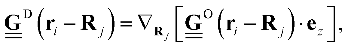 | (20) |
 | (21) |
 | (22) |
 | (23) |
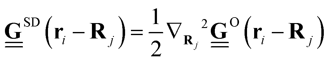
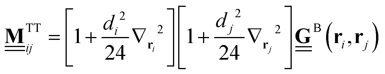
 , plugging eqn (19) into eqn (22), we find
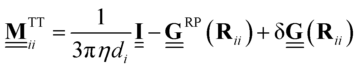 | (24) |
 | (25) |
 is the Rotne–Prager tensor and
  is the correction term from in addition to the Rotne–Prager contribution of the image particle, given by
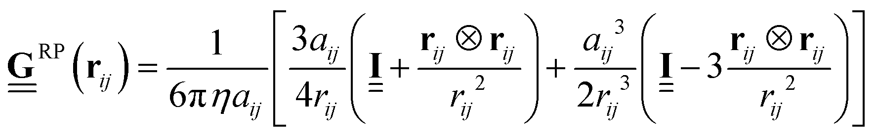 | (26) |
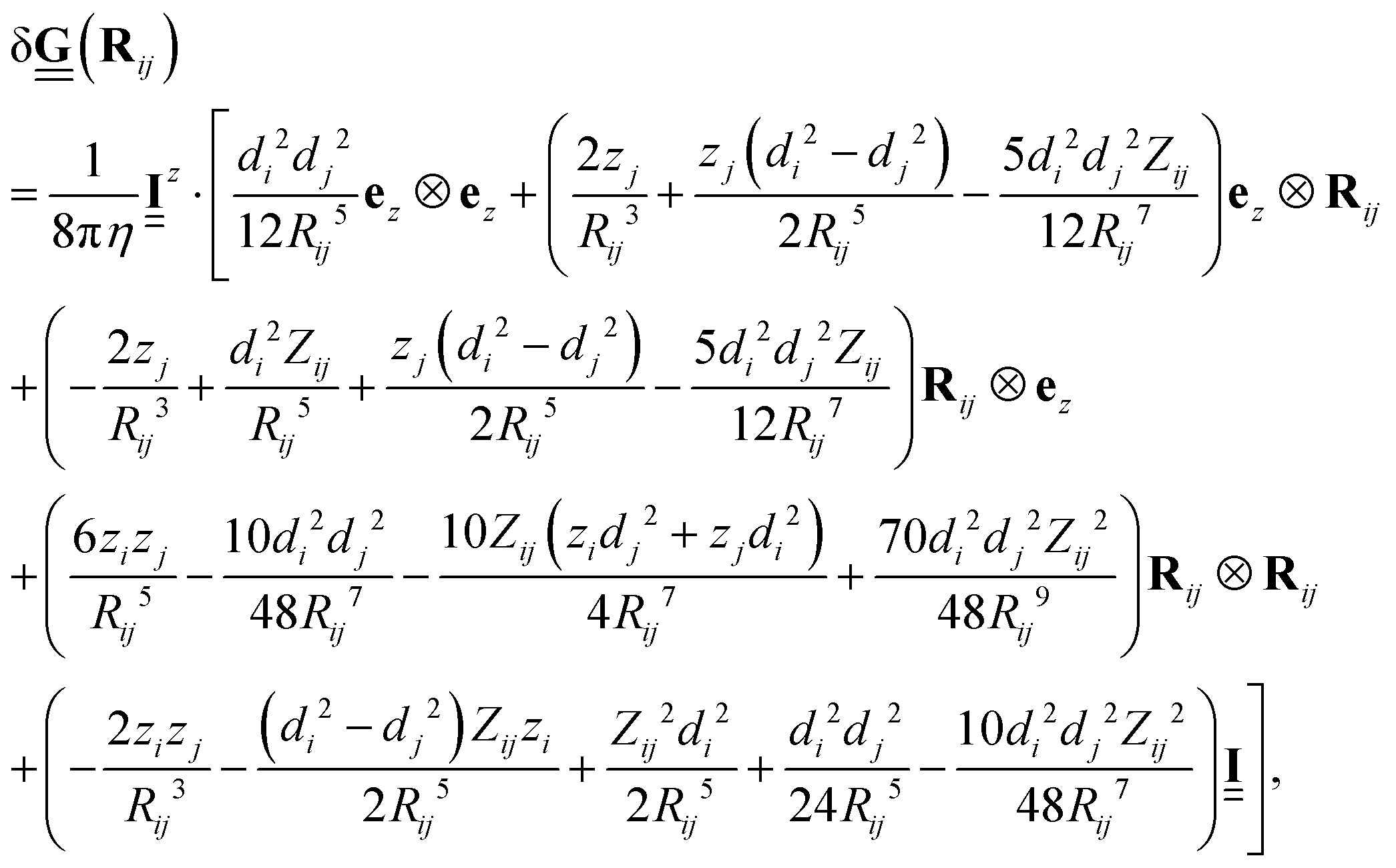 | (27) |
 being the effective radius of the two particles and Rij = ri − Rj being the distance between particle i and the image of particle j. Note that these expressions differ from that for polydisperse systems near a plane boundary condition, such as reported by Karzar-Jeddi et al. in ref. 53. Unfortunately, the latter seem to contain errors as the reported expressions do not reduce to that of ref. 52 in the limit of di = dj. For a detailed derivation of the above mentioned expressions see ref. 54.
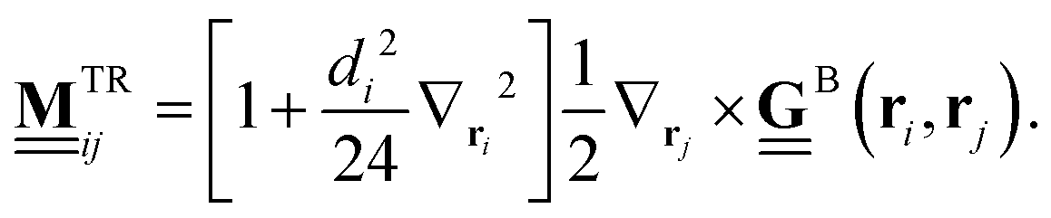
Turning now to  , plugging eqn (19) into eqn (23), we find
 | (28) |
 | (29) |
 is the Levi–Civita tensor, a third rank tensor which represents the cross product as follows
  . Note that these expressions are identical to that of the monodisperse case reported in ref. 52.
Acknowledgements
This research was funded by the Deutsche Forschungsgemeinschaft (DFG, German Research Foundation) – Projektnummer 163436311 – SFB 910. P. T. and A. O.-A. acknowledge support from the ERC Consolidator Grant (No. 811234). P. T. acknowledges support from MINECO (FIS2016-78507-C2, ERC2018-092827), DURSI (2017SGR1061), and Generalitat de Catalunya under Program “ICREA Acadmia”.Notes and references
- L. Berthier and G. Biroli, Rev. Mod. Phys., 2011, 83, 587–645 CrossRef CAS.
- D. Bonn, M. M. Denn, L. Berthier, T. Divoux and S. Manneville, Rev. Mod. Phys., 2017, 89, 035005 CrossRef.
- A. M. Puertas and T. Voigtmann, J. Phys.: Condens. Matter, 2014, 26, 243101 CrossRef CAS.
- M. A. Annunziata, A. Baldassarri, F. Dalton, A. Petri and G. Pontuale, J. Phys.: Condens. Matter, 2016, 28, 134001 CrossRef CAS.
- B. Bhushan, J. Israelachvili and U. Landman, Nature, 1995, 374, 607–616 CrossRef CAS.
- L. Ma and J. Luo, Friction, 2016, 4, 280–302 CrossRef.
- U. Raviv, S. Giasson, N. Kampf, J. Gohy, R. Jerome and J. Klein, Nature, 2003, 425, 163–165 CrossRef CAS.
- J. Atencia and D. Beebe, Nature, 2005, 437, 648–655 CrossRef CAS.
- D. Genovese and J. Sprakel, Soft Matter, 2011, 7, 3889–3896 RSC.
- R. Di Leonardo, L. Angelani, D. Dell'Arciprete, G. Ruocco, V. Iebba, S. Schippa, M. P. Conte, F. Mecarini, F. De Angelis and E. Di Fabrizio, Proc. Natl. Acad. Sci. U. S. A., 2010, 107, 9541–9545 CrossRef CAS.
- I. Williams, E. C. Oguz, T. Speck, P. Bartlett, H. Loewen and C. P. Royall, Nat. Phys., 2016, 12, 98–103 Search PubMed.
- A. Ortiz-Ambriz, S. Gerloff, S. H. L. Klapp, J. Ortin and P. Tierno, Soft Matter, 2018, 14, 5121–5129 RSC.
- W. Fornari, L. Brandt, P. Chaudhuri, C. U. Lopez, D. Mitra and F. Picano, Phys. Rev. Lett., 2016, 116, 018301 CrossRef.
- K. Yeo and M. R. Maxey, Phys. Rev. E: Stat., Nonlinear, Soft Matter Phys., 2010, 81, 051502 CrossRef.
- J. Huang, B. Yan, A. Faghihnejad, H. Xu and H. Zeng, Korea-Aust. Rheol. J., 2014, 26, 3–14 CrossRef.
- H. Wioland, E. Lushi and R. E. Goldstein, New J. Phys., 2016, 18, 075002 CrossRef.
- I. Cohen, T. Mason and D. Weitz, Phys. Rev. Lett., 2004, 93, 046001 CrossRef.
- P. Schall and M. van Hecke, Annu. Rev. Fluid Mech., 2010, 42, 67–88 CrossRef.
- G. P. Shrivastav, P. Chaudhuri and J. Horbach, Phys. Rev. E, 2016, 94, 042605 CrossRef.
- L. Isa, R. Besseling, A. N. Morozov and W. C. K. Poon, Phys. Rev. Lett., 2009, 102, 058302 CrossRef.
- M. Ramaswamy, N. Y. C. Lin, B. D. Leahy, C. Ness, A. M. Fiore, J. W. Swan and I. Cohen, Phys. Rev. X, 2017, 7, 041005 Search PubMed.
- S. Gerloff, T. A. Vezirov and S. H. L. Klapp, Phys. Rev. E, 2017, 95, 062605 CrossRef.
- N. Y. C. Lin and I. Cohen, Soft Matter, 2016, 12, 9058–9067 RSC.
- F. E. Mackay, K. Pastor, M. Karttunen and C. Denniston, Soft Matter, 2014, 10, 8724–8730 RSC.
- T. A. Vezirov and S. H. L. Klapp, Phys. Rev. E: Stat., Nonlinear, Soft Matter Phys., 2013, 88, 052307 CrossRef.
- D. Wilms, S. Deutschlaender, U. Siems, K. Franzrahe, P. Henseler, P. Keim, N. Schwierz, P. Virnau, K. Binder, G. Maret and P. Nielaba, J. Phys.: Condens. Matter, 2012, 24, 464119 CrossRef CAS.
- W. E. Uspal and P. S. Doyle, Soft Matter, 2012, 8, 10676–10686 RSC.
- J. R. Royer, D. L. Blair and S. D. Hudson, Phys. Rev. Lett., 2016, 116, 188301 CrossRef.
- H. A. Vinutha and S. Sastry, Nat. Phys., 2016, 12, 578 Search PubMed.
- S. Gerloff and S. H. L. Klapp, Phys. Rev. E, 2016, 94, 062605 CrossRef.
- D. McDermott, C. Olson Reichhardt and C. Reichhardt, Phys. Rev. E, 2016, 93, 062607 CrossRef CAS.
- T. Horn and H. Loewen, J. Chem. Phys., 2014, 141, 224505 CrossRef.
- F. Martinez-Pedrero, A. Ortiz-Ambriz, I. Pagonabarraga and P. Tierno, Phys. Rev. Lett., 2015, 115, 138301 CrossRef.
- A. V. Straube and P. Tierno, Soft Matter, 2014, 10, 3915–3925 RSC.
- D. V. Denisov, K. A. Lorincz, J. T. Uhl, K. A. Dahmen and P. Schall, Nat. Commun., 2016, 7, 10641 CrossRef CAS.
- S. Papanikolaou, Phys. Rev. E, 2016, 93, 032610 CrossRef.
- B. A. W. Brinkman, M. P. LeBlanc, J. T. Uhl, Y. Ben-Zion and K. A. Dahmen, Phys. Rev. E, 2016, 93, 013003 CrossRef.
- C. Zhou, C. Reichhardt, C. J. O. Reichhardt and I. J. Beyerlein, Sci. Rep., 2015, 5, 8000 CrossRef CAS.
- J. Zausch, J. Horbach, M. Laurati, S. U. Egelhaaf, J. M. Brader, T. Voigtmann and M. Fuchs, J. Phys.: Condens. Matter, 2008, 20, 404210 CrossRef.
- S. Gerloff and S. H. L. Klapp, Phys. Rev. E, 2018, 98, 062619 CrossRef CAS.
- A. Oritz-Ambriz, AODControls, 2020 DOI:10.5281/zenodo.4013935.
- D. Allan, C. van der Wel, N. Keim, T. A. Caswell, D. Wieker, R. Verweij, C. Reid, Thierry, L. Grueter, K. Ramos, Apiszcz, Zoeith, R. W. Perry, F. Boulogne, P. Sinha, Pfigliozzi, N. Bruot, L. Uieda, J. Katins, H. Mary and A. Ahmadia, soft-matter/trackpy: Trackpy v0.4.2, 2019 DOI:10.5281/zenodo.3492186#.XcWGhWSbUl4.mendeley.
- J. C. Crocker and D. G. Grier, J. Colloid Interface Sci., 1996, 179, 298 CrossRef CAS.
- J. Hasnain, S. Jungblut and C. Dellago, Soft Matter, 2013, 9, 5867–5873 RSC.
- R. Gernert, C. Emary and S. H. L. Klapp, Phys. Rev. E: Stat., Nonlinear, Soft Matter Phys., 2014, 90, 062115 CrossRef.
- C. Emary, R. Gernert and S. H. L. Klapp, Phys. Rev. E: Stat., Nonlinear, Soft Matter Phys., 2012, 86, 061135 CrossRef.
- M. Laurati, K. J. Mutch, N. Koumakis, J. Zausch, C. P. Amann, A. B. Schofield, G. Petekidis, J. F. Brady, J. Horbach, M. Fuchs and S. U. Egelhaaf, J. Phys.: Condens. Matter, 2012, 24, 464104 CrossRef CAS.
- B. Todd, D. Evans and P. Daivis, Phys. Rev. E: Stat., Nonlinear, Soft Matter Phys., 1995, 52, 1627–1638 CrossRef CAS.
- T. Speck, J. Mehl and U. Seifert, Phys. Rev. Lett., 2008, 100, 178302 CrossRef.
- U. Seifert, Rep. Prog. Phys., 2012, 75, 126001 CrossRef.
- J. R. Blake, Proc. Cambridge Philos. Soc., 1971, 70, 303–310 CrossRef.
- J. W. Swan and J. F. Brady, Phys. Fluids, 2007, 19, 113306 CrossRef.
- M. Karzar-Jeddi, H. Luo and P. T. Cummings, Comput. Fluids, 2018, 176, 40–50 CrossRef.
- S. Gerloff, Doctoral thesis, Technische Universität Berlin, Berlin, 2020.
Footnotes |
| † Electronic supplementary information (ESI) available. See DOI: 10.1039/d0sm01238f |
| ‡ Note that, in experiments, the distance between the top and bottom glass cover is approximately 100 μm. Since the particles sediment to the bottom substrate and their distance from the top cover is relatively large, we consider only the bottom boundary condition. |
| § For a closeup, see Fig. S1(a) in the ESI.† |
| ¶ These distributions are different from that of the distribution of the instantaneous angular velocity per ring ωn(t) during each realizations. These tend to be much wider and featureless, i.e. Gaussian, due to strong spatial fluctuations, data not shown. |
| This journal is © The Royal Society of Chemistry 2020 |