
 Open Access Article
 This Open Access Article is licensed under a
 Creative Commons Attribution 3.0 Unported Licence
Role of ion-selective membranes in the carbon balance for CO2 electroreduction via gas diffusion electrode reactor designs†
Ming
Ma
 a,
Sangkuk
Kim
ab,
Ib
Chorkendorff
a and
Brian
Seger
*a
a,
Sangkuk
Kim
ab,
Ib
Chorkendorff
a and
Brian
Seger
*a
aSurface Physics and Catalysis (SurfCat) Section, Department of Physics, Technical University of Denmark, 2800 Kgs. Lyngby, Denmark. E-mail: brse@fysik.dtu.dk
bSurface Chemistry Laboratory of Energy/Electronic Materials (SCHEMA), Department of Chemical Engineering, Pohang University of Science and Technology, Pohang 37673, Korea
First published on 3rd August 2020
Abstract
In this work, the effect of ion-selective membranes on the detailed carbon balance was systematically analyzed for high-rate CO2 reduction in GDE-type flow electrolyzers. By using different ion-selective membranes, we show nearly identical catalytic selectivity for CO2 reduction, which is primarily due to a similar local reaction environment created at the cathode/electrolyte interface via the introduction of a catholyte layer. In addition, based on a systematic exploration of gases released from electrolytes and the dynamic change of electrolyte speciation, we demonstrate the explicit discrepancy in carbon balance paths for the captured CO2 at the cathode/catholyte interface via reaction with OH− when using different ion-selective membranes: (i) the captured CO2 could be transported through an anion exchange membrane in the form of CO32−, subsequently releasing CO2 along with O2 in the anolyte, and (ii) with a cation exchange membrane, the captured CO2 would be accumulated in the catholyte in the form of CO32−, while (iii) with the use of a bipolar membrane, the captured CO2 could be released at the catholyte/membrane interface in the form of gaseous CO2. The unique carbon balance path for each type of membrane is linked to ion species transported through the membranes.
Introduction
The electrochemical reduction of CO2 to valuable chemicals and fuels powered by renewable electricity provides an attractive strategy to close the anthropogenic carbon cycle and store intermittent renewable energy.1–8 In the past, great efforts have been devoted to the development of selective, efficient and stable electrocatalysts in CO2-saturated aqueous solutions using H-type cells.9–16 Striking progress has been made in exploring catalysts for CO2 reduction in H-type cells. However, CO2 reduction in H-type cells only allows for relatively low current densities due to mass transport limitations in aqueous solutions.17–19 Large-scale utilization of electrochemical conversion of CO2 requires high reaction rates (i.e. high current densities). In this context, flow electrolyzers with gas-diffusion electrodes (GDEs) have gained considerable attention for CO2 reduction, owing to the fact that GDEs allow for a very thin mass-transfer boundary layer (∼50 nm).18,19 By using GDE-type flow electrolyzers, the mass-transport of CO2 and gaseous products on the surface of the catalysts can be accelerated, achieving commercially relevant current densities (>100 mA cm−2) along with high selectivity toward a desired product.20–29To date, most of the high-rate CO2 reduction studies based on GDE-type flow electrolyzers have been performed using anion exchange membranes (AEMs).20–29 However, our recent work demonstrated a substantial crossover of anionic CO2 reduction products such as acetate and formate through AEMs in GDE-type flow electrolyzers.29 More importantly, after the electrolytes reach a steady state, it was found that about 70% of the consumed CO2 is captured at the cathode/electrolyte interface via reaction with OH−, forming CO32−, which is transported to the anolyte via an AEM as a charge-carrier.29 Subsequently, CO32− coming from the catholyte reacts with H+ in the vicinity of the anode, releasing gaseous CO2 from the anolyte with the O2 stream, which means that most of the consumed CO2 (70%) is captured in the catholyte and emitted from the anolyte. In other words, only 30% of the CO2 consumed is involved in CO2 conversion into products. This finding indicates that many of the current techno-economic analyses for high-rate electroreduction of CO2 must be reconsidered if significant CO2 crossover occurs.29,30
One approach to reduce the CO2 crossover would be to use a two-step cascade process, which consists of an initial CO2 reduction to CO and a subsequent CO conversion into highly valuable multi-carbon products that have no carbon source crossover.31,32 However, even in this two-step procedure with 100% CO faradaic efficiency for the first step, 50% of all consumed CO2 could still be emitted out of the anolyte using an AEM.29 Theoretically, utilization of a cation exchange membrane (CEM) or a bipolar membrane (BPM) can prevent the CO2 crossover in GDE-type flow electrolyzers. However, only a few studies on high-rate CO2 reduction (>100 mA cm−2) have been carried out in GDE-type electrolyzers using CEMs33–35 or BPMs36–38 to date.
This study describes a systematic exploration of the effect of ion-selective membranes on the detailed carbon balance including CO2 consumption, products and CO2 crossover, as well as CO2 emission in GDE-type flow electrolyzers. Herein, we demonstrate the comparison of catalytic selectivity, CO2 consumption rate (via the reaction with OH−), and the dynamic change of electrolyte speciation among three different types of ion-selective membranes. By a systematic exploration of the gases released from the catholyte or anolyte, ion species change in the electrolyte and ion species transport via membranes, and this work provides mechanistic insights into the role of ion-selective membranes in carbon balancing for high-rate CO2 reduction.
Results and discussion
Electrocatalytic CO2 reduction performance
In this work, Cu electrocatalyst layers (∼70 nm) were prepared on top of microporous carbon layers of GDEs by magnetron sputtering at an argon pressure of 2 mTorr (Fig. S1†). The detailed materials characterization of the Cu catalyst layers on GDEs has been reported in our previous work.29 We conducted CO2 reduction electrolysis experiments in a three-compartment flow electrolyzer where a Cu catalyst coated on a GDE was positioned between the gas and catholyte chambers, as shown in Fig. 1a. An ion-selective membrane was used to separate the catholyte and anolyte flow chambers in which electrolytes continuously flow, and it should be noted that AEM, CEM and BPM were all tested in this work. During CO2 reduction, gaseous CO2 at a constant flow rate (45 ml min−1) was continuously fed into the gas chamber (Fig. 1a), and a fraction of the CO2 diffused to the surface of the catalysts in an electrolyte and then converted into gas products such as C2H4 and liquid products such as ethanol (Fig. 1b). Gas products mixed with the unreacted CO2 were directly vented into the gas-sampling loop of a gas chromatograph (GC) for periodic quantification. The liquid products were diluted and circulated in the given catholyte and anolyte reservoirs, and were detected via high-performance liquid chromatography (HPLC) after completion of the CO2 reduction electrolysis experiments.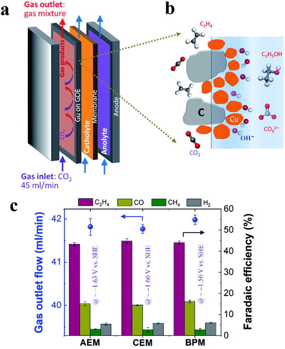 | ||
| Fig. 1 (a) Schematic illustration of three-compartment flow electrolyzers. (b) Schematic illustration of the cathode/electrolyte interface for CO2 conversion. (c) Rates of gas flow out of the gas chamber after CO2 reduction (left axis) and faradaic efficiencies for gas products (right axis) using different ion-selective membranes in 1 M KHCO3 at 200 mA cm−2. The iR-corrected potentials are labeled with purple color in (c). 45 ml min−1 CO2 inlet flow was used in all the experiments. | ||
In order to get reliable catalytic selectivity for gas products in high-rate CO2 reduction, gas flow out of the reactor was monitored via a volumetric flowmeter (Fig. S2†).29Fig. 1c shows that nearly identical gas flow rates were observed out of the electrolyzer when using an AEM, CEM and BPM in 1 M KHCO3 at 200 mA cm−2, indicating a similar CO2 consumption rate. This observation is primarily due to the same OH− generation rate via cathodic reactions (i.e. similar local pH created at the cathode/electrolyte interface). The faradaic efficiencies of gas products calculated using these corrected gas flow rates were plotted for different ion-selective membranes (Fig. 1c). As shown in Fig. 1c, C2H4 is the primary gas product for all the different ion-selective membranes, along with small amounts of CO and H2 and only trace amounts of CH4. Notably, the faradaic efficiencies for gaseous products had no obvious variation when different types of membranes were utilized (at nearly identical potentials, as shown in Fig. 1c). This result indicates that catalytic selectivity of gaseous products is independent of the type of ion-selective membrane for high-rate CO2 reduction in the three-compartment electrolyzers.
In addition to the detected gas products, liquid-phase products in both catholyte and anolyte were all analyzed due to the potential crossover of liquid products from the catholyte to the anolyte via membranes.39,40 As noted in Fig. 2a, substantial anionic CO2 reduction products (such as formate and acetate) crossed over from the catholyte to the anolyte via the AEM by electromigration, with only minimal crossover for uncharged liquid products. In contrast, the CEM and BPM exhibited negligible crossover for both anionic liquid products and uncharged products (Fig. 2a). This observation indicates that both CEM and BPM are capable of inhibiting the crossover of anionic and neutral liquid products.
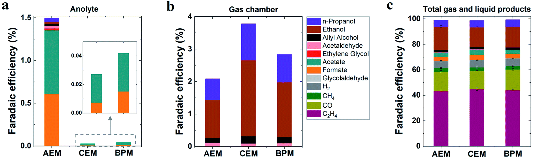 | ||
| Fig. 2 (a) Faradaic efficiencies for detected liquid products in anolyte and (b) faradaic efficiencies for liquid products evaporated from GDEs into the gas chamber. (c) Faradaic efficiencies for all detected gas and liquid products in 1 M KHCO3 at 200 mA cm−2 for various membranes. Total liquid products were counted via analysis of both catholyte and anolyte as well as liquid products evaporated from GDEs into the gas chamber. | ||
For determining the total amounts of liquid products, liquid products evaporated from GDEs into the gas chamber of the reactor were also collected for analysis (using a setup shown in Fig. S3†).41 No matter which type of ion-selective membrane was used, alcohol products such as n-propanol and ethanol experienced considerable evaporation through the gas diffusion layer of the GDE (Fig. 2b), which is due to their high volatility. In addition, we found that acetaldehyde had the highest evaporation ratio among liquid products (Fig. S4†). This finding may be attributed to two reasons, (i) its relatively high vapor pressure and (ii) its further reduction to ethanol on the cathode where a substantial amount of acetaldehyde was produced initially and subsequently converted into ethanol.42 Based on the quantification of liquid products in both catholyte and anolyte as well as liquid products evaporated from GDEs into the gas chamber (eqn (S12)†), faradaic efficiencies of all liquid products were evaluated for all the different types of membranes (Fig. 2c). As shown in Fig. 2c, ethanol was the dominant liquid product along with n-propanol, acetate and formate as minor products. There appears to be no significant variation in liquid product formation across all types of membranes. All the above results imply that the role of ion-selective membrane is almost negligible in affecting catalytic selectivity of high-rate CO2 reduction in the three-compartment electrolyzers, owing to the similar local reaction environment created on the cathode via the introduction of a catholyte layer. It should be noted that zero-gap electrolyzers lacking a catholyte layer have clearly shown the change of CO2 reduction selectivity by the different types of ion-selective membranes.43,44
Capture and emission of CO2 throughout the electrolyte
In accordance with our recent carbon balance study,29 the gases released from the anolyte were systematically explored for CO2 reduction via an AEM with 1 M KHCO3, elucidating a two-step procedure of CO2 capture at the cathode/electrolyte interface via reaction with OH− and subsequent CO2 degassing from the anolyte due to H+ in the vicinity of the anode (Scheme 1a). With the nearly identical catalytic selectivity (Fig. 2c) and similar total CO2 consumption rate (similar gas outlet shown in Fig. 1c), the same OH− generation rate via cathodic reactions means that the capability of capturing CO2 for carbonate formation at the cathode/electrolyte interface using a CEM and BPM should be similar to that of an AEM. Thus, for a CEM and BPM, substantial additional carbonate anions produced in the reaction of CO2 and OH− generated via the cathodic reactions must be either balanced with extra cation species (the total anion charge equals the total cation charge) or emitted from the electrolyte as gaseous CO2. To uncover the role of different membrane types in the carbon balance for flow electrolyzers, gases released from the electrolyte were detected for the CEM and BPM, respectively (using a closed-cycle anolyte with a vent for gases shown in Fig. S5†).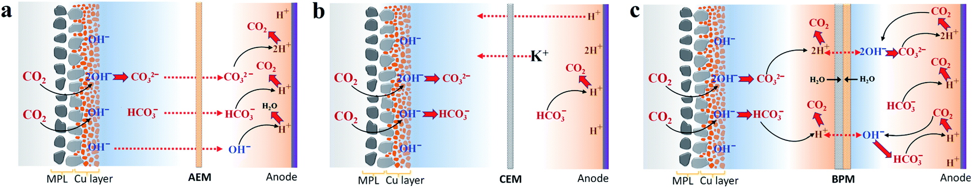 | ||
| Scheme 1 Proposed carbon balance paths via CO2 capture at the cathode/catholyte interface and CO2 evolution from the anolyte or catholyte in flow electrolyzers combined with an AEM (a), CEM (b) and BPM (c), respectively, while using KHCO3 as the initial catholyte and anolyte. Red dashed lines with arrows indicate the probable charge-carrying ionic species for membranes. Carbon balance paths for the AEM were adapted from ref. 29. | ||
Theoretically, the composition ratio of CO2/O2 in the gas stream from the anolyte will be 4, 2 or 0 if the only anion species for neutralizing H+ generated on the anode is HCO3−, CO32− or OH−.28,29 In addition, under the consideration that HCO3−, CO32− or OH− is the only anion species of neutralization reaction with H+, the theoretically calculated CO2 flow rate will be 6.0, 3.0 or 0 ml min−1 at 200 mA cm−2 with a geometric active area of 2 cm2 (Table S2†).
Fig. 3a–c show the comparison of gases released in the anolyte over the course of electrolysis for all the different ion-selective membranes. When an AEM was used, the CO2/O2 ratio decreased from ∼3 to ∼2 in the first 4 h and then remained at ∼2 over the remaining course of electrolysis. This observation is due to the fact that the CO2 evolution via the H+ neutralization reaction changed rapidly from a mixture of HCO3− and CO32− to nearly pure CO32− using the AEM (Fig. 3a). In contrast, as noted in Fig. 3b, the CEM experienced a consistent CO2/O2 ratio of ∼4 and a constant CO2 flow rate of 6 ml min−1 for the duration of electrolysis at 200 mA cm−2, which implies that the CO2 formation was always derived from HCO3− in the anolyte. This finding is ascribed to the fact that the CO32− formed via CO2 capture in the catholyte cannot be transported to the anolyte via the CEM since the functional groups (typically SO3− groups) only allow cation species (such as K+) to pass through (Scheme 1b). It should be noted that the CO2 reduction electrolysis via the CEM was tested for just ∼3 h, since the anolyte conductivity rapidly decreased from ∼70 mS cm−1 to ∼3 mS cm−1 after ∼3 h (Fig. S8b†), which is consistent with previous work.45 All the above results with the CEM indicate that almost no anionic species were transported to the anolyte via the membrane, but cation species such as K+ served as the main charge carrier via the CEM. Thus, the concentration of KHCO3 in the anolyte was significantly reduced over time as K+ was constantly transported to the catholyte and the remaining HCO3− in the anolyte was consumed for CO2 evolution (Scheme 1b).
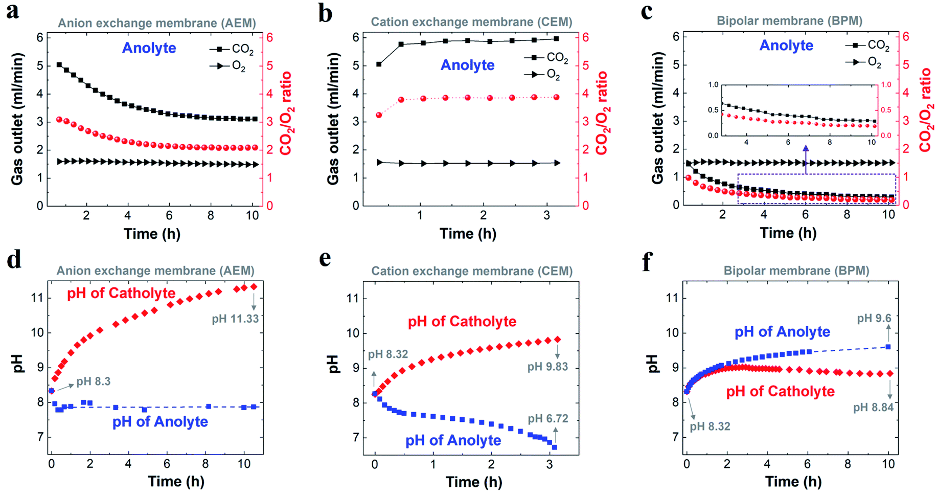 | ||
| Fig. 3 Comparison of flow of CO2 and O2 released from the anolyte (left axis), and corresponding ratio of CO2 to O2 (right axis) when using an AEM (a), CEM (b) and BPM (c) over the course of CO2 reduction electrolysis at 200 mA cm−2. Variation in related electrolyte pH during CO2 reduction electrolysis for an AEM (d), CEM (e) and BPM (f), respectively. In all the experiments, 1 M KHCO3 was used as the initial catholyte (50 ml) and anolyte (50 ml). (a) and (d) for AEM were adapted based on ref. 29. | ||
A bipolar membrane is composed of a cation exchange layer (CEL) and an anion exchange layer (AEL) as well as a catalyst layer that is sandwiched between the CEL and AEL. The catalyst layer in a BPM dissociates water (fed from both the catholyte and anolyte) into H+ and OH−, which is subsequently transported to the catholyte and anolyte via the CEL and AEL, respectively (Scheme 1c).46 With the use of a BPM (Fig. 3c), the flow rate of CO2 released from the anolyte rapidly decreased from 1.4 ml min−1 to 0.5 ml min−1 in the first 4 h, corresponding to a decline in the CO2/O2 ratio from ∼1 to ∼0.3. This observation may be linked to the fact that an alkaline boundary layer near the AEL of the BPM created via the constant supply of OH− from the BPM was unfavorable for releasing CO2 (the distance between the anode and the membrane was ∼3 mm). In addition, the almost constant conductivity in both catholyte and anolyte over the 10 h electrolysis (Fig. S8c†) may imply that neither anionic species (CO32− or HCO3−) nor cationic species (K+) had any apparent crossover. This result reveals that the additional anion species (CO32− or HCO3−) generated by CO2 capture could not be accumulated in the catholyte during CO2 reduction electrolysis due to the charge balance issue (the total anion charge must equal the total cation charge). Thus, the additional CO32− or HCO3− should be emitted from the catholyte as gaseous CO2. As expected, gas bubbles released from the catholyte were observed when a BPM was used (no gas evolution was observed in the catholyte using an AEM or CEM), and this gas evolution immediately disappeared after stopping the electrolysis.
To verify the CO2 degassing in the catholyte, the gases released from the catholyte during the CO2 reduction electrolysis were analyzed using a setup shown in Fig. 4a. Fig. 4b shows CO2 degassing from the catholyte when using a BPM, owing to the neutralization reaction of CO32− or HCO3− with H+ near the CEL of the BPM (Scheme 1c), which is in line with previous BPM work.37 In addition, the related flow rate of CO2 released from the catholyte slightly decreased from ∼3.5 ml min−1 to ∼2.6 ml min−1, and was maintained at ∼2.6 ml min−1 over the electrolysis experiment (Fig. 4b). This observation can be attributed to the fact that the carbon source (anion species) for CO2 evolution abruptly transformed from a mixture of HCO3− and CO32− to almost pure CO32−. In addition, a fraction of CO2 released from the catholyte chamber can transport to the cathode surface to be reused for both CO2 reduction37 and the buffering reaction with OH− at the cathode/electrolyte interface. This back-diffusion effect leads to a slightly lower CO2 flow (∼2.6 ml min−1) compared to the theoretical value (3.0 ml min−1). Furthermore, with nearly identical catalytic selectivity (Fig. 2c) and the same OH− generation rate on the cathode (due to the same current density) among all the different membranes, the utilization of a fraction of CO2 released from a catholyte with a BPM results in a slightly lower CO2 consumption rate in the gas chamber. This result is in line with the slightly higher gas outlet flow rate for the BPM in comparison with those of the AEM and CEM (Fig. 1c).
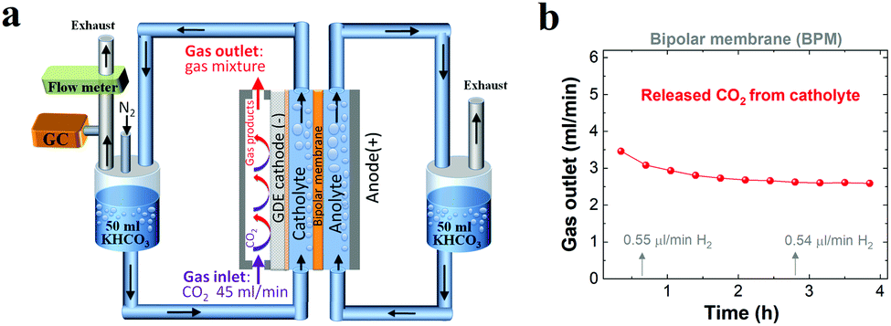 | ||
| Fig. 4 (a) Schematic illustration of the flow cell setup for detecting gases released from the catholyte over the course of CO2 reduction when using a BPM (N2 with a constant flow rate was used as a carrier gas). (b) Flow rate of CO2 released from the catholyte when using a BPM for CO2 reduction at 200 mA cm−2 with a negligible amount of H2. 1 M KHCO3 was used as the initial catholyte (50 ml) and anolyte (50 ml). | ||
While each type of ion-selective membrane had a different flow rate of CO2 released from the anolyte, O2 was detected with a constant flow rate of ∼1.5 ml min−1 during the electrolysis irrespective of membrane type (Fig. 3a–c). This finding is consistent with the theoretical value of the O2 flow rate (1.5 ml min−1 shown in Table S2†) at 200 mA cm−2 for a geometric active area of 2 cm2.
To further understand the transformation of anionic species in the electrolyte, the pH of the electrolyte was also monitored over the course of the electrolysis for all the membranes. Fig. 3e shows that for a CEM the catholyte pH was enhanced from 8.3 to nearly 9.8 after ∼3 h. The catholyte pH with the AEM increased to 10.2 after ∼3 h under identical conditions. Thus, the similar increasing trend in catholyte pH between the AEM and CEM over 3 h indicates that the captured CO2 at the cathode/electrolyte interface (via reaction with OH−) mainly formed CO32− using the CEM,29 leading to CO32− acting as the dominant anion species in the catholyte after 3 h. The catholyte pH with the BPM was maintained below 9 over the entire electrolysis experiment (Fig. 3f) due to the fact that a constant supply rate of H+ from water dissociation in the BPM enables carbonate and bicarbonate concentrations in the catholyte to reach a steady sate. In addition, this pH < 9 also indicates that most of the existing anion species in the catholyte was bicarbonate over the entire electrolysis (Table S4†). However, the observed CO2 flow rate (2.6 ml min−1) from the catholyte (after reaching a steady state) also reveals that CO2 was captured and converted to CO32− at the cathode/electrolyte interface, and then combined with the aforementioned H+ at the BPM/catholyte interface to release CO2. In addition, it should be noted that the theoretical calculations have shown that the pH near the cathode is ∼13 in 1 M KHCO3 at 200 mA cm−2,18 which means that the reaction of CO2 with OH− at the cathode/electrolyte interface forms CO32− instead of HCO3− (eqn (S8) and (S9)†). Thus, all these results reveal that the CO2 captured by the electrolyte near the cathode formed CO32− irrespective of membrane type.
We found that the anolyte quickly reached a near neutral pH for both the AEM and the CEM during the electrolysis (Fig. 3d and e), which allows for CO2 degassing in the anolyte. Specifically, the anolyte pH with the AEM was maintained at ∼7.9 after 20 min (Fig. 3d), owing to the fact that the constant H+ generation rate near the anode and continuous carbonate supply derived from the catholyte created a steady state for all the anion species in the anolyte via the neutralization reactions (Scheme 1a). In contrast, with the CEM, the anolyte pH rapidly decreased from 8.3 to 6.7 over 3 h (Fig. 3e). This finding is due to the fact that the CO2 degassing with the continuous consumption of KHCO3 in the anolyte created a CO2-saturated KHCO3 anolyte and its concentration gradually reduced over time (pH of CO2-saturated 0.1 M KHCO3 is ∼6.8). Interestingly, a slow increase in the anolyte pH from 8.3 to 9.6 was observed over 10 h electrolysis when using the BPM, as shown in Fig. 3f. This observation may be linked to a slow variation in the anionic species concentrations (here, an increase in the CO32−/HCO3− ratio was likely created) in the anolyte during the electrolysis. This slow alteration is ascribed to the fact that the anolyte species did not completely reach a steady-state within 10 h electrolysis via the two major reactions, (i) the reaction of CO2 with OH− at the BPM/anolyte interface forming CO32−/HCO3−, and (ii) simultaneously, CO32−/HCO3− converting into CO2 near the anode (Scheme 1c).
Carbon balance via different types of membranes and implications
For high-rate CO2 reduction in flow electrolyzers, the carbon source for CO2 fed from the inlet of the reactor must be balanced with that of all CO2 reduction products, CO2 captured by electrolyte (carbonate formation) and residual CO2 out of the reactor (i.e. unreacted CO2). As noted in Fig. 5a, (i) the flow rate of residual unreacted CO2 out of the reactor, (ii) the flow rate of CO2 consumed for carbonate formation via the reaction with OH− (i.e. captured CO2 throughout the electrolyte) and (iii) the flow rate of consumed CO2 that was converted into all the gaseous and liquid products add up to a total CO2 flow rate of ∼45 ml min−1 for each type of ion-selective membrane. Thus, the carbon element during the electrolysis is balanced with that of the CO2 inlet flow rate (45 ml min−1) in this work. In addition, Fig. 5b shows the nearly identical CO2 consumption rate for the formation of gaseous and liquid products using different ion-selective membranes, which is in line with the roughly same catalytic selectivity shown in Fig. 2c.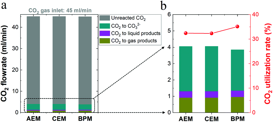 | ||
| Fig. 5 (a) Carbon balance for high-rate CO2 reduction in 1 M KHCO3 using different membranes. The unreacted (i.e. residual) CO2 flow rate as well as the total consumed CO2 flow rate for carbonate formation and CO2 reduction to all liquid and gas products were considered. (b) Ratio of CO2 converted into products to total CO2 consumption (right axis). | ||
It should be noted that there should be nearly the same carbonate formation rate (via CO2 reaction with OH−) near the cathode among all the different membranes due to the identical OH− generation rate via cathodic reactions at identical current densities. While membrane types should have a minimal effect on the total carbonate formation rate near the cathode, the BPM had a slightly lower consumption rate of CO2 from the gas chamber for carbonate formation compared to those of the AEM and CEM, as shown in Fig. 5b. This finding correlates with the discrepancy in carbon balance paths among the three different types of membranes. In other words, while the unavoidable CO2 capture near the cathode forms carbonate in the catholyte, the end result of where the carbonate goes is different in each type of membrane. For the CEM, the captured CO2 was accumulated in the form of carbonate in the catholyte without emission. In contrast, when the AEM was used, the captured CO2 in the form of carbonate crossed over to the anolyte and was emitted as gaseous CO2 with the O2 stream in the anolyte. Notably, with the BPM, the captured CO2 could be released from the catholyte as gaseous CO2. Thus, a fraction of the generated CO2 in the catholyte may be involved in the reaction with OH− for carbonate formation, which corresponds to a relatively low consumption rate of CO2 in the gas chamber for carbonate formation (∼65% of the total CO2 consumption), as shown in Fig. 5b. In addition, the reuse of a fraction of the released CO2 in the catholyte, derived from the captured CO2 in the form of carbonate, also results in a slightly higher CO2 utilization rate of the BPM (ratio of CO2 converted into products versus total CO2 consumption) in Fig. 5b.
From an economic and environmental perspective, the released CO2 from the electrolyte in flow electrolyzers would need to be captured and recycled. When the AEM is used, the released CO2 in the anolyte can only be recycled for CO2 reduction after removing O2 in the gas mixture (mole ratio of CO2/O2 is 2![[thin space (1/6-em)]](https://www.rsc.org/images/entities/char_2009.gif) :1). Interestingly, the BPM could degas CO2 from the catholyte, which can be directly fed into the gas compartment for CO2 conversion due to its high purity (∼100% CO2 by mole). Thus, compared to the necessary CO2 and O2 separation process for CO2 recycling with the AEM, the BPM has the potential to reduce the total cost of the carbon source. However, it should be noted that using a BPM for high-rate CO2 reduction (current densities > 100 mA cm−2) currently requires an additional potential (>∼1.5 V) for membranes that may reduce the energy efficiency of CO2 conversion reactors.47 In this work, an additional potential of ∼2 V was observed when using the BPM at 200 mA cm−2 (Fig. S9†). Thereby, how to balance the energy efficiency along with the easy recyclability of the produced CO2 in the catholyte (from inevitably captured CO2) with the use of BPMs will need a full techno-economic analysis in the future.
:1). Interestingly, the BPM could degas CO2 from the catholyte, which can be directly fed into the gas compartment for CO2 conversion due to its high purity (∼100% CO2 by mole). Thus, compared to the necessary CO2 and O2 separation process for CO2 recycling with the AEM, the BPM has the potential to reduce the total cost of the carbon source. However, it should be noted that using a BPM for high-rate CO2 reduction (current densities > 100 mA cm−2) currently requires an additional potential (>∼1.5 V) for membranes that may reduce the energy efficiency of CO2 conversion reactors.47 In this work, an additional potential of ∼2 V was observed when using the BPM at 200 mA cm−2 (Fig. S9†). Thereby, how to balance the energy efficiency along with the easy recyclability of the produced CO2 in the catholyte (from inevitably captured CO2) with the use of BPMs will need a full techno-economic analysis in the future.
Conclusions
In conclusion, our results show that the role of ion-selective membranes is minimal in affecting the catalytic selectivity of high-rate CO2 reduction, owing to the nearly same local reaction environment created near the catalysts through having a catholyte layer. By rigorously analyzing gases released from electrolytes as well as monitoring electrolyte pH, we found that most of the consumed CO2 source (≥∼65%) was captured via reaction with OH− near the cathode to form CO32−, which is almost independent of membrane type.Importantly, each type of ion-selective membrane produces a unique carbon balance path for the captured CO2 source. Specifically, the captured CO2 in the form of CO32− could cross an AEM from the catholyte to the anolyte and then be emitted as gaseous CO2 mixed with the O2 stream. In contrast, the captured CO2 could not be transported to the anolyte when using a CEM or BPM. With a CEM, captured CO2 in the form of carbonate continuously accumulated in the catholyte, since there was no concomitant H+ supply for CO2 evolution (mainly K+ crossed the membrane). With the bipolar membrane, the captured CO2 was released from the catholyte as gaseous CO2, owing to the reaction of carbonate with H+ transported from its cation exchange layer. In addition, while for an AEM CO2 was emitted together with O2, for a BPM the pure CO2 was released, which can be directly recycled back to the gas compartment for CO2 conversion, correspondingly decreasing the cost of the CO2 source. This study shows that while the catalytic selectivity is independent of the type of ion-selective membrane, membrane type plays an important role in the corresponding carbon balance path for high-rate CO2 reduction. Thus, future work should focus on membrane exploration for achieving the practical utilization of high-rate CO2 reduction.
Author contributions
M. M. and B. S. developed the conceptual idea, designed the experiments and wrote the original manuscript. S. K. carried out a part of the electrolyte pH and conductivity measurements. All authors contributed to discussing the results and editing the manuscript.Conflicts of interest
There are no conflicts to declare.Acknowledgements
This work was supported by Villum Foundation V-SUSTAIN grant 9455 to the Villum Center for the Science of Sustainable Fuels and Chemicals. This work was also supported by the ECOEthylene project from Innovation Fund Denmark (Grant# 8057-00018B), SELECTCO2 project from Horizon 2020 of the EU (Grant# 851441) and National Research Foundation of Korea (NRF-2019R1A2C2002156). The authors would like to thank Dr Ezra L. Clark for technical support with HPLC.Notes and references
- Z. W. Seh, J. Kibsgaard, C. F. Dickens, I. Chorkendorff, J. K. Nørskov and T. F. Jaramillo, Science, 2017, 355, eaad4998 CrossRef PubMed.
- C. W. Li, J. Ciston and M. W. Kanan, Nature, 2014, 508, 504–507 CrossRef CAS PubMed.
- D. D. Zhu, J. L. Liu and S. Z. Qiao, Adv. Mater., 2016, 28, 3423–3452 CrossRef CAS PubMed.
- M. G. Kibria, J. P. Edwards, C. M. Gabardo, C. Dinh, A. Seifitokaldani, D. Sinton and E. H. Sargent, Adv. Mater., 2019, 31, 1807166 CrossRef PubMed.
- K. Jiang, R. B. Sandberg, A. J. Akey, X. Liu, D. C. Bell, J. K. Nørskov, K. Chan and H. Wang, Nat. Catal., 2018, 1, 111–119 CrossRef CAS.
- M. Ma, K. Djanashvili and W. A. Smith, Angew. Chem., Int. Ed., 2016, 55, 6680–6684 CrossRef CAS PubMed.
- D. T. Whipple and P. J. A. Kenis, J. Phys. Chem. Lett., 2010, 1, 3451–3458 CrossRef CAS.
- P. De Luna, C. Hahn, D. Higgins, S. A. Jaffer, T. F. Jaramillo and E. H. Sargent, Science, 2019, 364, eaav3506 CrossRef CAS PubMed.
- Y. Chen, C. W. Li and M. W. Kanan, J. Am. Chem. Soc., 2012, 134, 19969–19972 CrossRef CAS PubMed.
- K. J. P. Schouten, Z. Qin, E. Pérez Gallent and M. T. M. Koper, J. Am. Chem. Soc., 2012, 134, 9864–9867 CrossRef CAS PubMed.
- Q. Lu, J. Rosen, Y. Zhou, G. S. Hutchings, Y. C. Kimmel, J. G. Chen and F. Jiao, Nat. Commun., 2014, 5, 3242 CrossRef PubMed.
- M. Ma, B. J. Trześniewski, J. Xie and W. A. Smith, Angew. Chem., Int. Ed., 2016, 55, 9748–9752 CrossRef CAS PubMed.
- M. Liu, Y. Pang, B. Zhang, P. De Luna, O. Voznyy, J. Xu, X. Zheng, C. T. Dinh, F. Fan, C. Cao, F. P. G. de Arquer, T. S. Safaei, A. Mepham, A. Klinkova, E. Kumacheva, T. Filleter, D. Sinton, S. O. Kelley and E. H. Sargent, Nature, 2016, 537, 382–386 CrossRef CAS PubMed.
- H. Mistry, A. S. Varela, C. S. Bonifacio, I. Zegkinoglou, I. Sinev, Y.-W. Choi, K. Kisslinger, E. A. Stach, J. C. Yang, P. Strasser and B. R. Cuenya, Nat. Commun., 2016, 7, 12123 CrossRef PubMed.
- M. Ma, K. Liu, J. Shen, R. Kas and W. A. Smith, ACS Energy Lett., 2018, 3, 1301–1306 CrossRef CAS PubMed.
- S. Nitopi, E. Bertheussen, S. B. Scott, X. Liu, A. K. Engstfeld, S. Horch, B. Seger, I. E. L. Stephens, K. Chan, C. Hahn, J. K. Nørskov, T. F. Jaramillo and I. Chorkendorff, Chem. Rev., 2019, 119, 7610–7672 CrossRef CAS PubMed.
- N. Gupta, M. Gattrell and B. MacDougall, J. Appl. Electrochem., 2005, 36, 161–172 CrossRef.
- T. Burdyny and W. A. Smith, Energy Environ. Sci., 2019, 12, 1442–1453 RSC.
- L. C. Weng, A. T. Bell and A. Z. Weber, Phys. Chem. Chem. Phys., 2018, 20, 16973–16984 RSC.
- S. Ma, M. Sadakiyo, M. Heima, R. Luo, R. T. Haasch, J. I. Gold, M. Yamauchi and P. J. A. Kenis, J. Am. Chem. Soc., 2017, 139, 47–50 CrossRef CAS PubMed.
- T. T. H. Hoang, S. Verma, S. Ma, T. T. Fister, J. Timoshenko, A. I. Frenkel, P. J. A. Kenis and A. A. Gewirth, J. Am. Chem. Soc., 2018, 140, 5791–5797 CrossRef CAS PubMed.
- C.-T. Dinh, T. Burdyny, M. G. Kibria, A. Seifitokaldani, C. M. Gabardo, F. P. García de Arquer, A. Kiani, J. P. Edwards, P. De Luna, O. S. Bushuyev, C. Zou, R. Quintero-Bermudez, Y. Pang, D. Sinton and E. H. Sargent, Science, 2018, 360, 783–787 CrossRef CAS PubMed.
- F. Li, A. Thevenon, A. Rosas-Hernández, Z. Wang, Y. Li, C. M. Gabardo, A. Ozden, C. T. Dinh, J. Li, Y. Wang, J. P. Edwards, Y. Xu, C. McCallum, L. Tao, Z. Liang, M. Luo, X. Wang, H. Li, C. P. O'Brien, C. Tan, D. Nam, R. Quintero-Bermudez, T. Zhuang, Y. C. Li, Z. Han, R. D. Britt, D. Sinton, T. Agapie, J. C. Peters and E. H. Sargent, Nature, 2020, 577, 509–513 CrossRef CAS PubMed.
- T. Möller, W. Ju, A. Bagger, X. Wang, F. Luo, T. Ngo Thanh, A. S. Varela, J. Rossmeisl and P. Strasser, Energy Environ. Sci., 2019, 12, 640–647 RSC.
- R. Wang, H. Haspel, A. Pustovarenko, A. Dikhtiarenko, A. Russkikh, G. Shterk, D. Osadchii, S. Ould-Chikh, M. Ma, W. A. Smith, K. Takanabe, F. Kapteijn and J. Gascon, ACS Energy Lett., 2019, 4, 2024–2031 CrossRef CAS.
- C. M. Gabardo, A. Seifitokaldani, J. P. Edwards, C. T. Dinh, T. Burdyny, M. G. Kibria, C. P. O'Brien, E. H. Sargent and D. Sinton, Energy Environ. Sci., 2018, 11, 2531–2539 RSC.
- J.-J. Lv, M. Jouny, W. Luc, W. Zhu, J.-J. Zhu and F. Jiao, Adv. Mater., 2018, 30, 1803111 CrossRef PubMed.
- G. O. Larrazábal, P. Strøm-Hansen, J. P. Heli, K. Zeiter, K. T. Therkildsen, I. Chorkendorff and B. Seger, ACS Appl. Mater. Interfaces, 2019, 11, 41281–41288 CrossRef PubMed.
- M. Ma, E. L. Clark, K. T. Therkildsen, S. Dalsgaard, I. Chorkendorff and B. Seger, Energy Environ. Sci., 2020, 3, 977–985 RSC.
- D. Reinisch, B. Schmid, N. Martić, R. Krause, H. Landes, M. Hanebuth, K. J. J. Mayrhofer and G. Schmid, Z. Phys. Chem. DOI:10.1515/zpch-2019-1480.
- M. Jouny, W. Luc and F. Jiao, Nat. Catal., 2018, 1, 748–755 CrossRef CAS.
- D. S. Ripatti, T. R. Veltman and M. W. Kanan, Joule, 2019, 3, 240–256 CrossRef CAS.
- D. Kopljar, A. Inan, P. Vindayer, N. Wagner and E. Klemm, J. Appl. Electrochem., 2014, 44, 1107–1116 CrossRef CAS.
- E. J. Dufek, T. E. Lister, S. G. Stone and M. E. McIlwain, J. Electrochem. Soc., 2012, 159, F514–F517 CrossRef CAS.
- C. Reller, R. Krause, E. Volkova, B. Schmid, S. Neubauer, A. Rucki, M. Schuster and G. Schmid, Adv. Energy Mater., 2017, 7, 1602114 CrossRef.
- D. A. Salvatore, D. M. Weekes, J. He, K. E. Dettelbach, Y. C. Li, T. E. Mallouk and C. P. Berlinguette, ACS Energy Lett., 2018, 3, 149–154 CrossRef CAS.
- Y. C. Li, G. Lee, T. Yuan, Y. Wang, D.-H. Nam, Z. Wang, F. P. García de Arquer, Y. Lum, C.-T. Dinh, O. Voznyy and E. H. Sargent, ACS Energy Lett., 2019, 4, 1427–1431 CrossRef CAS.
- A. Pătru, T. Binninger, B. Pribyl and T. J. Schmidt, J. Electrochem. Soc., 2019, 166, F34–F43 CrossRef.
- Y. C. Li, Z. Yan, J. Hitt, R. Wycisk, P. N. Pintauro and T. E. Mallouk, Adv. Sustainable Syst., 2018, 2, 1700187 CrossRef.
- M. Krödel, B. M. Carter, D. Rall, J. Lohaus, M. Wessling and D. J. Miller, ACS Appl. Mater. Interfaces, 2020, 12, 12030–12042 CrossRef PubMed.
- J. Zhang, W. Luo and A. Züttel, J. Catal., 2020, 385, 140–145 CrossRef CAS.
- E. L. Clark and A. T. Bell, J. Am. Chem. Soc., 2018, 140, 7012–7020 CrossRef CAS PubMed.
- C. Delacourt, P. L. Ridgway, J. B. Kerr and J. Newman, J. Electrochem. Soc., 2008, 155, B42 CrossRef CAS.
- B. Endrődi, G. Bencsik, F. Darvas, R. Jones, K. Rajeshwar and C. Janáky, Prog. Energy Combust. Sci., 2017, 62, 133–154 CrossRef.
- M. Lin, L. Han, M. R. Singh and C. Xiang, ACS Appl. Energy Mater., 2019, 2, 5843–5850 CrossRef CAS.
- D. A. Vermaas, S. Wiegman, T. Nagaki and W. A. Smith, Sustainable Energy Fuels, 2018, 2, 2006–2015 RSC.
- D. Salvatore and C. P. Berlinguette, ACS Energy Lett., 2020, 5, 215–220 CrossRef CAS.
Footnote |
| † Electronic supplementary information (ESI) available. See DOI: 10.1039/d0sc03047c |
| This journal is © The Royal Society of Chemistry 2020 |