DOI:
10.1039/C9SC05875C
(Edge Article)
Chem. Sci., 2020,
11, 661-670
A side-chain engineering strategy for constructing fluorescent dyes with direct and ultrafast self-delivery to living cells†
Received
19th November 2019
, Accepted 26th November 2019
First published on 4th December 2019
Abstract
Organic fluorescent dyes with excellent self-delivery to living cells are always difficult to find due to the limitation of the plasma membrane having rigorous selectivity. Herein, in order to improve the permeability of dyes, we utilize a side-chain engineering strategy (SCES): adjusting the side-chain length of dyes to fine-tune the adsorption and desorption processes on the membrane–aqueous phase interfaces of the outer and inner leaflets of the plasma membrane. For this, a family of fluorescent derivatives (SPs) was prepared by functionalizing a styryl-pyridinium fluorophore with alkyl side-chains containing a different carbon number from 1 to 22. Systematic experimental investigations and simulated calculations demonstrate that the self-delivery rate of SPs with a suitable length side-chain is about 22-fold higher in SiHa cells and 76-fold higher in mesenchymal stem cells than that of unmodified SP-1, enabling cell-imaging at an ultralow loading concentration of 1 nM and deep penetration in turbid tissue and in vivo. Moreover, the SCES can even endow a membrane-impermeable fluorescent scaffold with good permeability. Further, quantitative research on the relationship between Clog![[thin space (1/6-em)]](https://www.rsc.org/images/entities/char_2009.gif) P and cell permeability shows that when ClogP is in the range of 1.3–2.5, dyes possess optimal permeability. Therefore, this work not only systematically reports the effect of side-chain length on dye delivery for the first time, but also provides some ideal fluorescent probes. At the same time, it gives a suitable ClogP range for efficient cellular delivery, which can serve as a guide for designing cell-permeant dyes. In a word, all the results reveal that the SCES is an effective strategy to dramatically improve dye permeability.
P and cell permeability shows that when ClogP is in the range of 1.3–2.5, dyes possess optimal permeability. Therefore, this work not only systematically reports the effect of side-chain length on dye delivery for the first time, but also provides some ideal fluorescent probes. At the same time, it gives a suitable ClogP range for efficient cellular delivery, which can serve as a guide for designing cell-permeant dyes. In a word, all the results reveal that the SCES is an effective strategy to dramatically improve dye permeability.
Introduction
Organic fluorescent dyes have become indispensable tools in biology, pathology, medicine, and diagnosis, in the quest to investigate significant bioevents and visualize ions, active molecules, biomacromolecules, and organelles in living cells under fluorescence microscopy.1–5 However, due to the rigorous selectivity of the plasma membrane to substances entering the cells, the self-delivery of many extraneous organic dyes to living cells is often very poor.6,7 To this end, various strategies have been explored, including mechanical (microinjection), chemical (ATP, Triton X-100, and saponin), electrical (electric shock), and vehicular (liposome fusion).8–10 Unfortunately, these available strategies require mandatory treatment of cells, resulting in irreversible destruction of living cells. Then, Tsien et al. developed a noninvasive method to deliver organic dyes into living cells, via the AM esterification of carboxyl groups.11 In comparison, this strategy avoids direct damage to live cells and the operation procedure is facile. However, it is only applicable to modifying dyes with carboxyl or hydroxyl groups, and partially esterified compounds will release highly toxic formaldehyde accompanied by hydrolysis within cells.12,13 Recently, the transmembrane peptide method has also been used to transport exogenous substances into the cells. However, the process is affected by not only the peptide sequence and physicochemical properties, but also the local peptide concentration, local lipid composition, etc.14 Therefore, a simple, universal, and harmless dye delivery strategy avoiding the above problems is very necessary.
Generally, foreign organic dyes pass through the plasma membrane via a simple diffusion mechanism. The transmembrane process can be divided into three steps:15–17 (1) adsorption to the membrane–aqueous phase interface of the outer leaflet of the plasma membrane; (2) passing through the lipid bilayer to the opposite interface; (3) desorption from this interface into cells. Amongst these, the second step is considered rapid and easy, while the first and third steps are the rate-determining steps. As a result, the adsorption onto the outer leaflet of the plasma membrane and the subsequent release from the inner leaflet to the cytoplasm determines the delivery rate of dye molecules. And the rates of the two processes raise different requirements for molecular design. Consequently, fast dye self-delivery should be achieved by tuning the two contradictory requirements.
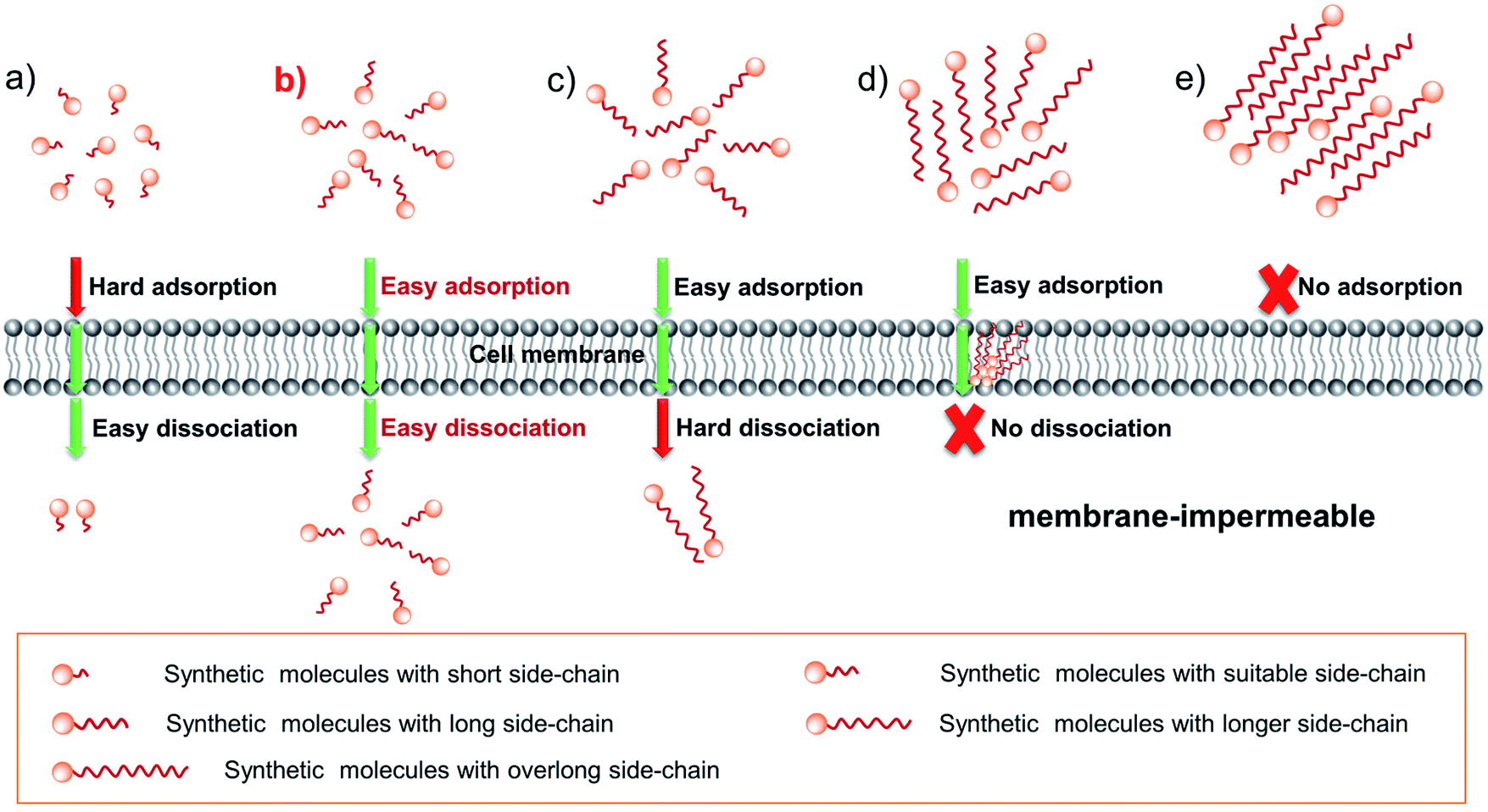
How can we adjust the rate of adsorption and desorption? We know that in drug design, a common method for improving drug permeability is to change its side-chain length.18 In addition, we also found that: (1) for many dyes with a short side-chain it is difficult or even impossible to enter living cells, such as various reported biosensors19–21 as well as commercial Ethidium Bromide (EB) and Propidium Iodide (PI); (2) numerous dyes with a long side-chain are often stranded in the plasma membrane, as evidenced by various plasma membrane probes.22–24 According to these facts mentioned above, one can rationally envision that tuning the side-chain length can change the cell permeability of dyes by influencing the transmembrane process. And the expected results are shown in Scheme 1: for short chain dye molecules, only a small portion can enter the cell due to poor adsorbability (Scheme 1a); as the side-chain is increased to a suitable length, dyes have the best permeability due to the obviously enhanced adsorptive and dissociative performances (Scheme 1b); upon continuing to extend the side-chain length, the molecular permeability will greatly decrease (Scheme 1c) and even become zero (Scheme 1d), owing to the poor dissociative ability; finally, an overlong chain causes molecules to be impossible to be adsorbed onto the membrane surface (Scheme 1e), because the overlong chain makes the dye water-insoluble in an aqueous culture medium. Although these assumptions should be rational, many important research studies and experimental data are still lacking for fluorescent dyes: (1) the effect of the SCES on the delivery of a fluorescent scaffold and relevant simulated calculations have still not been systematically investigated; (2) the degree to which the dye's permeability can be improved by the side-chain engineering strategy is still unclear; (3) in particular, can the SCES endow a membrane-impermeable fluorescent dye with good permeability?
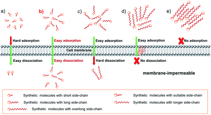 |
| | Scheme 1 Schematic diagram illustrating the self-delivery behaviors of synthetic molecules with side chains of different lengths (a–e). Here, the molecular arrangements do not represent their real states and only represent the number of molecules. | |
In order to fully address these concerns, herein, we prepare a family of styryl-pyridinium salts (abbreviated as SPs, Scheme 2) with side chains containing different carbon numbers (CN) from 1 to 22. Systematic experimental studies and discussion of the mechanism reveal that with the increase of the side-chain length, the permeability of SPs first increases and then decreases, which well supports the rational guesses shown in Scheme 1. Notably, among them, SP-6, SP-8, and SP-10 with appropriate side chains possess ultrafast cellular permeability, which enables cell-imaging with an unprecedentedly ultralow concentration of 1 nM and deep penetration in turbid tissues and in vivo. Moreover, the SCES also makes a membrane-impermeable dye (9E-BMVC1)20 smoothly enter the cells by modifying two hexyls. Compared with previously reported delivery methods, the SCES is simple and straightforward, avoiding destructive treatment of living cells. Therefore, when one hopes to deliver a valuable yet low permeability or impermeable fluorescent scaffold to living cells, one can first consider the SCES.
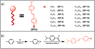 |
| | Scheme 2 The chemical structures (a) and synthetic route (b) of fluorescent dyes (SPs). | |
Results and discussion
The selection of a representative fluorescent scaffold
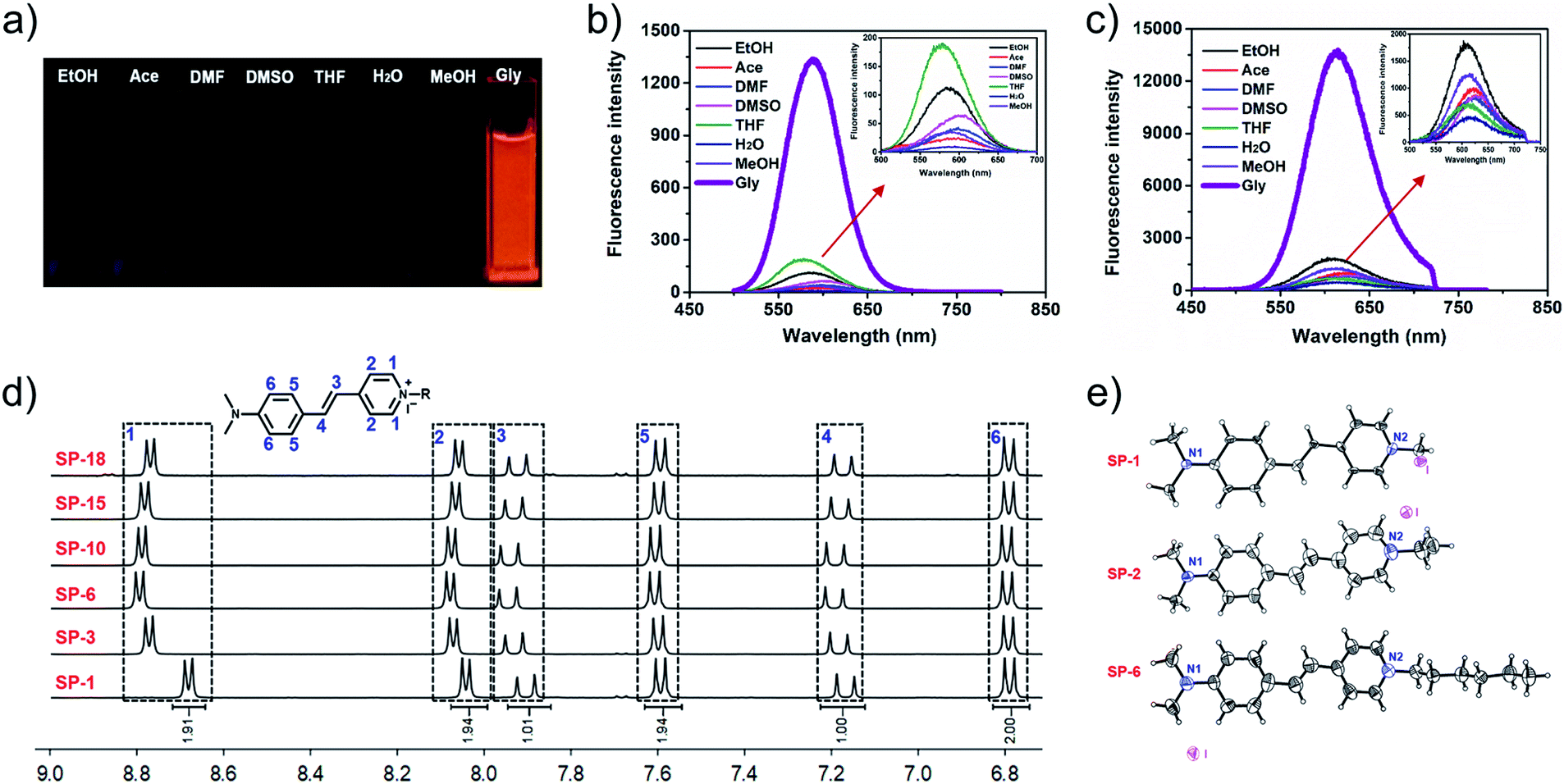
In order to investigate the effect of the side-chain length on dye delivery by the commonly used laser scanning confocal microscopy (LSCM), there are two requirements that need to be satisfied. Firstly, the platform should exhibit a small molecular structure in order to maximize the effect from sidechains. Secondly, these dyes should possess appropriate absorption and emission wavelengths that can be compatible with LSCM. For these requirements, the classic fluorophore styryl-pyridinium salt (SP-1), namely trans-4-(4′-N,N-dialkylaminostyryl)-N-methylpyridinium (abbreviated as SP-1 in Scheme 2), can be utilized as the dye platform.25–28 On one hand, SP-1 is easy to synthesize and has a pyridinium moiety that can be readily modified with side-chains of different lengths by a simple one-step reaction. On the other hand, as shown in Fig. 1a–c, Table S1 and Fig. S1–S3,†SP-1 can be excited at 473 nm (the commonly used excitation wavelength of LSCM), and it also exhibits red emission suitable for bioimaging. In addition, SP-1 also shows suitable two-photon properties. Therefore, a family of SPs from SP-1 to SP-22 was prepared, and the detailed synthesis and structural characterization were displayed in the ESI.†
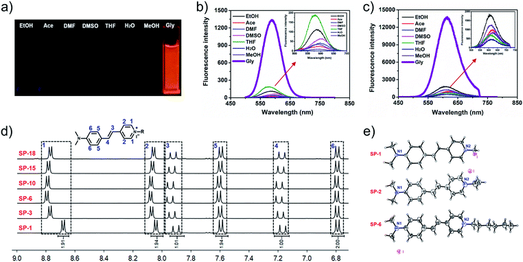 |
| | Fig. 1 Photographs taken under UV light with 365 nm excitation (a), OPEF (b) and TPEF (c) spectra of SP-1 in various solvents; inset: the enlarged parts indicated by the red arrow in (b and c); test concentration: 10 μM; λex (OPEF) = 473 nm; λex (TPEF) = 900 nm. (d) Partial 1H NMR spectra of SPs in DMSO-d6 (total 1H NMR spectra are shown in Fig. S4†). (e) Single-crystal structures of SP-1, SP-2, and SP-6, respectively, with dihedral angles of 11°, 16.38°, and 5.77° between the two aromatic rings. | |
The SCES does not change the chemical and optical properties and cytotoxicity of the fluorescent scaffold
As shown in the 1H NMR spectra of SPs (Fig. 1d and S4†), introducing a side-chain does not change the chemical shift of the protons of the conjugated fluorophore. Meanwhile, the single crystal structures of the three compounds (SP-1, SP-2, and SP-6) also indicate that the different side-chain lengths have little influence on the molecular planarity and bond length, despite the different packing patterns (Fig. 1e and S5–S7†). In addition, the side-chain also does not change their photophysical characteristics (as summarized in Table 1 and Fig. S8†). Moreover, all these SPs have an almost uniform molar extinction coefficient (ε), maximum absorption wavelength, one-photon excitation fluorescence (OPEF) and TPEF emission wavelengths, and even Φ and δ × Φ in the same solvent. Also, their anti-photobleaching abilities are almost the same. Additionally, different side-chain lengths also do not change the cytotoxicity of the SPs, as demonstrated by MTT assays in Fig. S9.† Therefore, the SCES does not change the chemical and optical properties and cytotoxicity of the fluorescent scaffold.
Table 1 Photophysical properties of SPsa
| Dyes |
λ
Abs
|
logε |
λ
em
1
|
Δλ |
λ
em
2
|
Φ (%) |
δ × Φ |
Anti-photobleaching |
| MeOH |
70% Gly |
MeOH |
70% Gly |
MeOH |
70% Gly |
MeOH |
70% Gly |
MeOH |
70% Gly |
MeOH |
70% Gly |
MeOH |
70% Gly |
MeOH |
DMF |
|
λ
Abs: the maximum absorption wavelength, ε: the molar extinction coefficient; λem1: the maximum OPEF wavelength, Δλ: the Stokes shift, λem2: the maximum TPEF wavelength (unit: nm); Φ: the fluorescence quantum yield; δ × Φ: the two-photon active absorption cross-section; anti-photobleaching: the fluorescence intensity of SPs after 900 s relative to the original intensity. λex (OPEF) = 473 nm; λex (TPEF) = 900 nm.
|
|
SP-1
|
475 |
479 |
3.79 |
4.74 |
591 |
590 |
116 |
111 |
611 |
609 |
0.13 |
2.00 |
0.36 |
3.53 |
90% |
92% |
|
SP-2
|
476 |
481 |
3.54 |
4.45 |
591 |
591 |
115 |
110 |
610 |
610 |
0.21 |
2.56 |
0.21 |
1.99 |
89% |
92% |
|
SP-3
|
479 |
483 |
3.52 |
4.48 |
591 |
591 |
112 |
108 |
611 |
611 |
0.20 |
2.74 |
0.23 |
2.32 |
92% |
91% |
|
SP-6
|
478 |
485 |
3.58 |
4.64 |
590 |
593 |
112 |
108 |
611 |
611 |
0.22 |
2.76 |
0.28 |
3.07 |
91% |
90% |
|
SP-8
|
478 |
484 |
3.49 |
4.48 |
590 |
592 |
112 |
108 |
610 |
611 |
0.20 |
2.37 |
0.24 |
2.74 |
90% |
90% |
|
SP-10
|
478 |
484 |
3.59 |
4.56 |
591 |
593 |
113 |
109 |
611 |
610 |
0.18 |
2.45 |
0.30 |
3.43 |
91% |
89% |
|
SP-12
|
479 |
484 |
3.70 |
4.63 |
592 |
592 |
113 |
108 |
610 |
609 |
0.20 |
2.48 |
0.39 |
3.58 |
88% |
89% |
|
SP-14
|
479 |
484 |
3.58 |
4.46 |
592 |
590 |
113 |
106 |
613 |
610 |
0.23 |
3.00 |
0.26 |
2.58 |
91% |
89% |
|
SP-15
|
479 |
485 |
3.78 |
4.75 |
590 |
590 |
111 |
105 |
613 |
610 |
0.17 |
2.31 |
0.48 |
4.45 |
91% |
88% |
|
SP-16
|
479 |
484 |
3.68 |
4.58 |
590 |
593 |
111 |
109 |
614 |
610 |
0.22 |
2.70 |
0.34 |
3.31 |
90% |
89% |
|
SP-18
|
479 |
485 |
3.64 |
4.57 |
593 |
592 |
114 |
107 |
612 |
610 |
0.22 |
2.83 |
0.35 |
3.91 |
90% |
89% |
|
SP-22
|
479 |
485 |
3.74 |
4.69 |
594 |
593 |
115 |
108 |
613 |
609 |
0.20 |
2.27 |
0.43 |
4.35 |
91% |
88% |
The effect of the SCES on the delivery behaviours of SP dyes
To investigate the delivery manner of SPs, we selected SP-1, SP-6, SP-12, and SP-14 as representatives to incubate with living SiHa cells at different temperatures (4 °C and 37 °C).6,29 As shown in Fig. S10,† the fluorescence images indicate that they can all clearly illuminate the intracellular structures. Moreover, the intracellular fluorescence intensity at 4 °C shows only a slight decline compared with that at 37 °C (Fig. S10b†), indicating that the transport of SPs through the plasma membrane is not energy-dependent active transport or endocytosis.30 Since there is no assistance of specific transporters or channel proteins for transporting SP molecules, SPs do not undergo facilitated diffusion. Thus, the delivery mechanism for SPs should be simple diffusion, which is a simple and non-destructive delivery method to living cells.
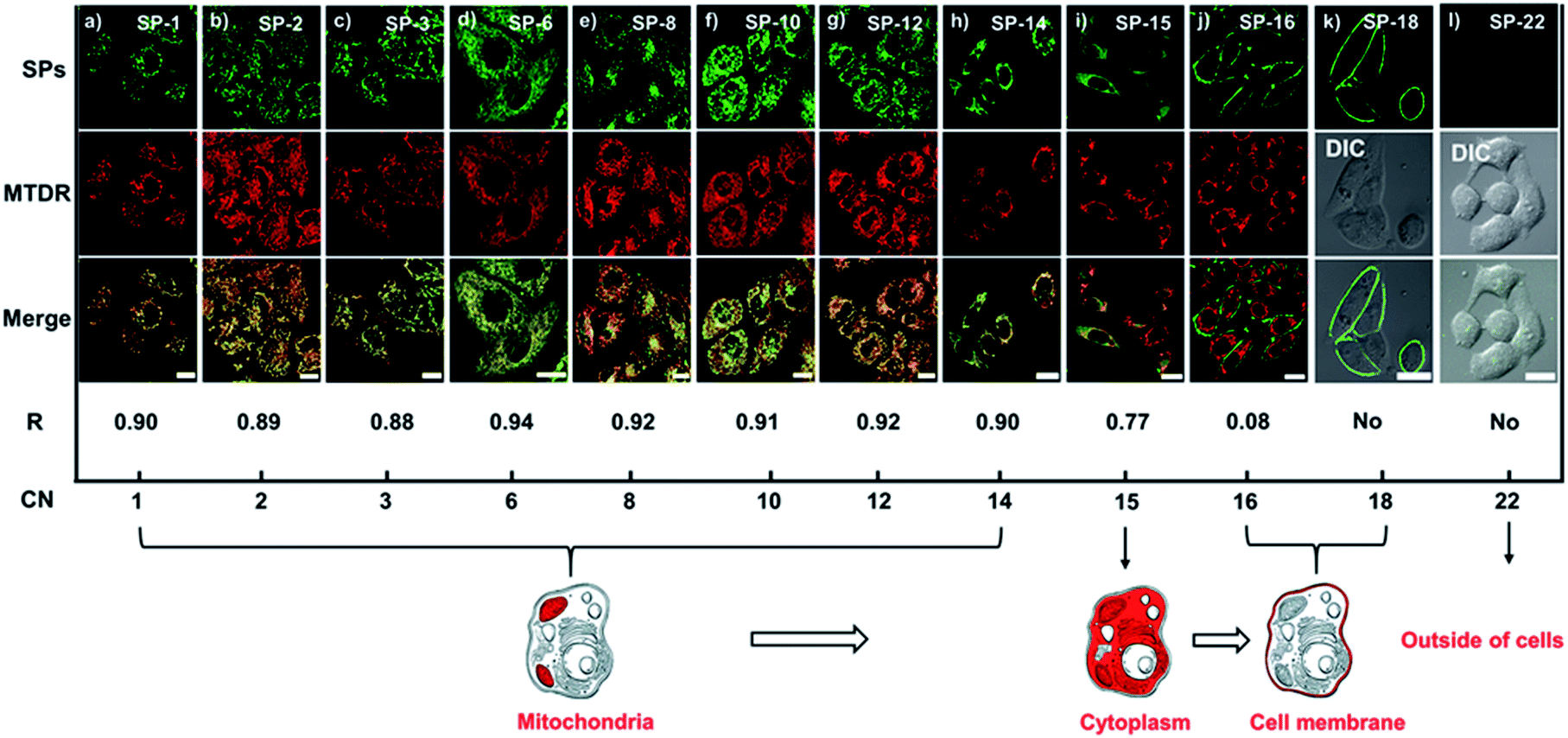
The subcellular location of SPs in living cells is speculated to be around the mitochondria, as cationic dyes tend to accumulate in the mitochondria due to the large negative mitochondrial membrane potential (MMP);31 thus MTDR (a commercial mitochondrial deep-red probe) was used as a co-stain with SPs. As shown in Fig. S11,† there are no crosstalk fluorescence signals between SPs and MTDR. From co-localization experiments, we can see that SPs with CNs from 1 to 14 can all enter living cells and show over a 0.88 co-localization coefficient with MTDR in Fig. 2a–h, indicating that they are mitochondria-targeting. Notably, the time used for staining cells highly depends on the side-chain length. In particular, SP-6, SP-8, and SP-10 can perform ultrafast delivery within 30 s, while SP-15 barely enters the cells and cannot locate an organelle, mainly due to the obstruction from the long chain (Fig. 2i). SP-16 (Fig. 2j) and SP-18 (Fig. 2k) are stranded in the plasma membrane and cannot enter the cells, because of the strong interaction between their long side-chains and the plasma membrane. And SP-22 cannot stain cells (Fig. 2l), because of the poor water-solubility in the aqueous culture medium. Therefore, the above results explicitly reveal that the length of the side-chain has a significant effect on the delivery behavior of dyes to living cells.
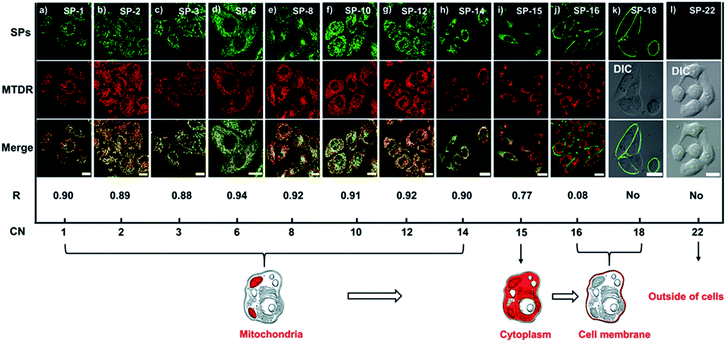 |
| | Fig. 2 (a–l) LSCM images of SiHa cells stained with SPs (200 nM) and MTDR (200 nM, 30 min), and their co-localization coefficients (R), as well as the changes in the staining location with the increase of the side-chain CN; amongst these, (k) and (l) do not show staining of the mitochondria. Staining time: 10 min for SP-1, SP-2, SP-3, SP-15, and SP-16; 30 s for SP-6, SP-8, and SP-10; 3 min for SP-12 and SP-14; 40 min for SP-18 and SP-22. λex (SPs) = 473 nm, λem (SPs) = 550–650 nm; λex (MTDR) = 633 nm, λem (MTDR) = 650–750 nm. Bar = 20 μm. | |
Assessing the SCES effect on the delivery rate and amount of SPs by experimental methods
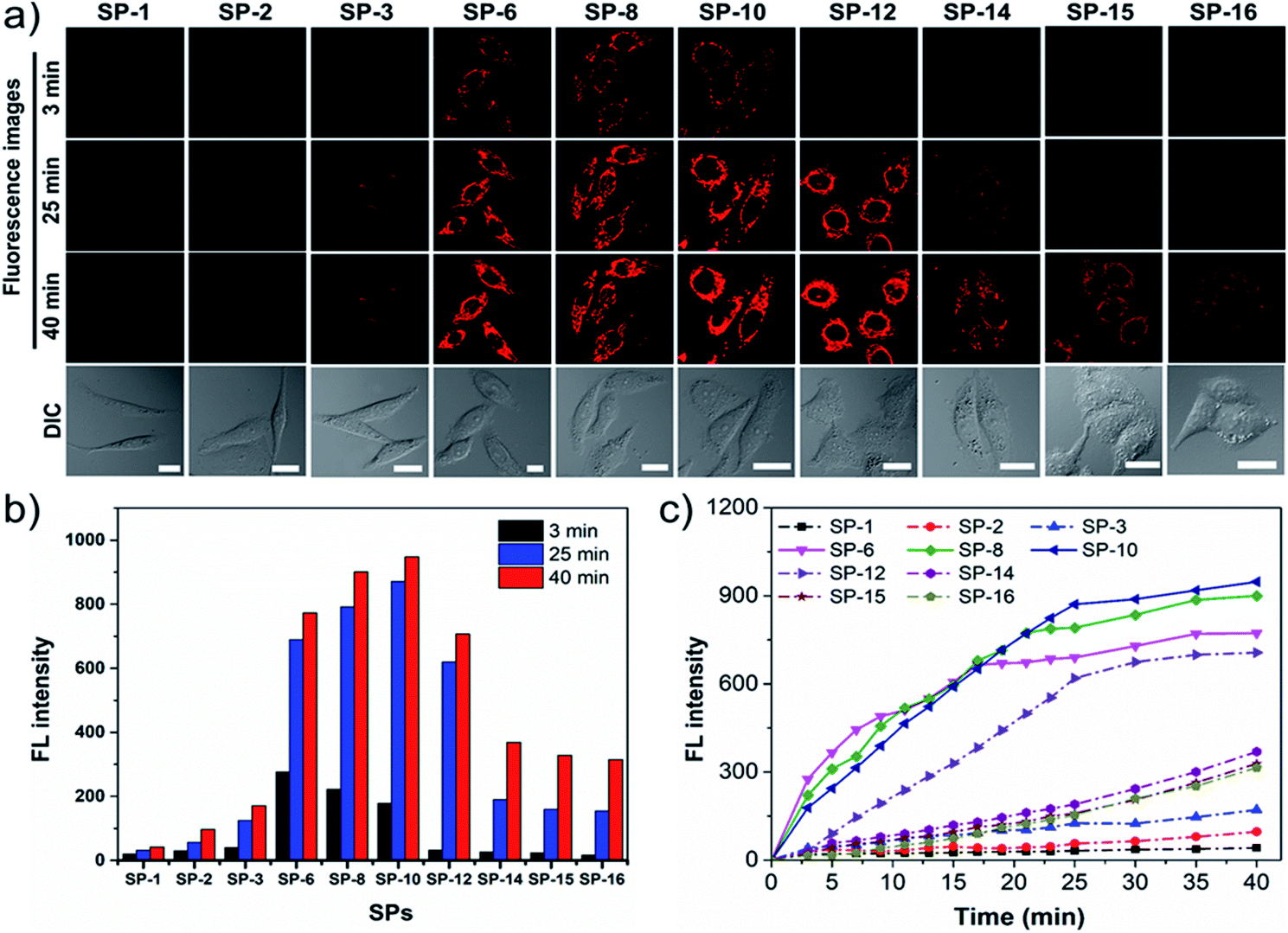
Given that SP-18 stained the plasma membrane and SP-22 aggregated in the aqueous medium, SPs with side-chain CNs in the range of 1–16 were selected for detailed study of the effect of side-chain length on dye delivery. Firstly, time-dependent dynamic analysis (TDDA)32 of SPs was conducted. In this experiment, living SiHa cells stained with SPs of 200 nM were immediately observed by LSCM. To avoid overexposed fluorescence, the imaging parameters such as PMT gain, laser power, and offset were set to be low and consistent. As shown in Fig. 3a, after incubation for 3 min, only SP-6, SP-8, and SP-10 exhibit visible intracellular fluorescence while others have almost no fluorescence, which indicate that more amounts of SP-6, SP-8 and SP-10 enter living cells. When stained for a longer time, their fluorescence can be clearly seen; however, the fluorescence from other SPs is still rather weak. The fluorescence intensity at different times (Fig. 3b) also shows that the three dyes have obvious increments. In particular, at 40 min, their fluorescence intensity is about 22-fold stronger than that of SP-1. Further, plots of fluorescence intensity versus incubation time (Fig. 3c) reveal that their intensity growth rates are apparently faster than those of other SPs. In addition, similar results have also been seen in normal MSC: with the increase of the side-chain length, the fluorescence intensity increases first and then decreases, and when the side-chain length is between 6 and 10, the intensity reaches the maximum, up to 76-fold higher than that of SP-1 (Fig. S12†). Therefore, the above results shed light on an important scientific discovery: we can control dye delivery by changing the alkyl-chain length and obtain ideal fluorescent probes with optimal cell permeability.
 |
| | Fig. 3 TDDA for diffusion dynamics of SPs in SiHa cells. (a) LSCM images of cells stained with SPs (200 nM) at different time points (3, 25, and 40 min) and the corresponding DIC images. (b) Time-dependent fluorescence intensity of SPs recorded at different time points. (c) The fluorescence intensity plots of SPs over time. λex = 473 nm, λem = 550–650 nm. Bar = 20 μm. | |
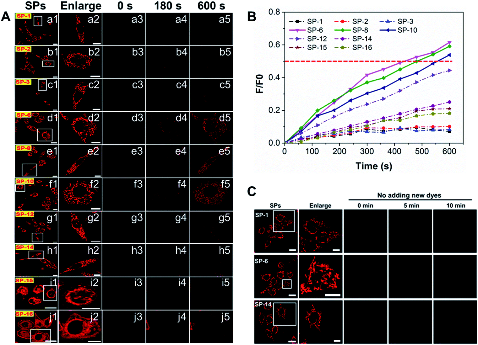
To obtain more information on the effect of the side-chain length on dye delivery, the fluorescence recovery after photobleaching (FRAP) method33 was reasonably adopted.33 Herein, living cells are well stained with SPs of 200 nM and then the residual dyes in the medium were washed off with PBS. Next, we selected a region of interest to take a picture at their own appropriate imaging parameter settings (PMT gain, laser intensity, and offset), as displayed in a1–j1 of Fig. 4A. Then, a single cell was enlarged to fill the viewing area (a2–j2 in Fig. 4A). After this, the fluorescence was rapidly and totally extinguished using a high-power laser (a3–j3 in Fig. 4A) and then imaging parameters were returned to their original levels. Maintaining the same observation position, new 200 nM SPs pre-dissolved in the culture medium were added to ensure that the concentration of all SPs outside the quenched cell was the same at that moment. Over time, newly added dyes will again diffuse into the quenched cells and the fluorescence signal will begin to recover. Notably, the control experiments of quenched cells without adding new 200 nM dyes show that the quenched fluorescence cannot spontaneously recover during the observation time (Fig. 4C), which indicates that restored fluorescence comes from newly added dyes. As shown in a4–j4 and a5–j5 of Fig. 4A, the fluorescence recovery rates of SP-6, SP-8, and SP-10 are much faster relative to those of other SPs. Moreover, from the fluorescence recovery curves in Fig. 4B, the fluorescence of only the three dyes can be restored to 50% relative to the initial state, demonstrating their excellent membrane permeability.
 |
| | Fig. 4 FRAP analysis for diffusion dynamics of SPs in SiHa cells. (A) (a–j): (1) LSCM images; (2) enlarged images of the white boxes in (1), which indicate the bleached regions selected; (3) the bleached images; (4 and 5) the representative FRAP images at different times. (B) The fluorescence intensity ratios of the enlarged cell in the whole FRAP process (0–600 s) relative to the unbleached ones (2). (C) The control experiment in which the fluorescence was quenched and no new dye was added. λex = 473 nm, λem = 550–650 nm; concentration: 200 nM. Bar (original images) = 20 μm; bar (enlarged images) = 10 μm. | |
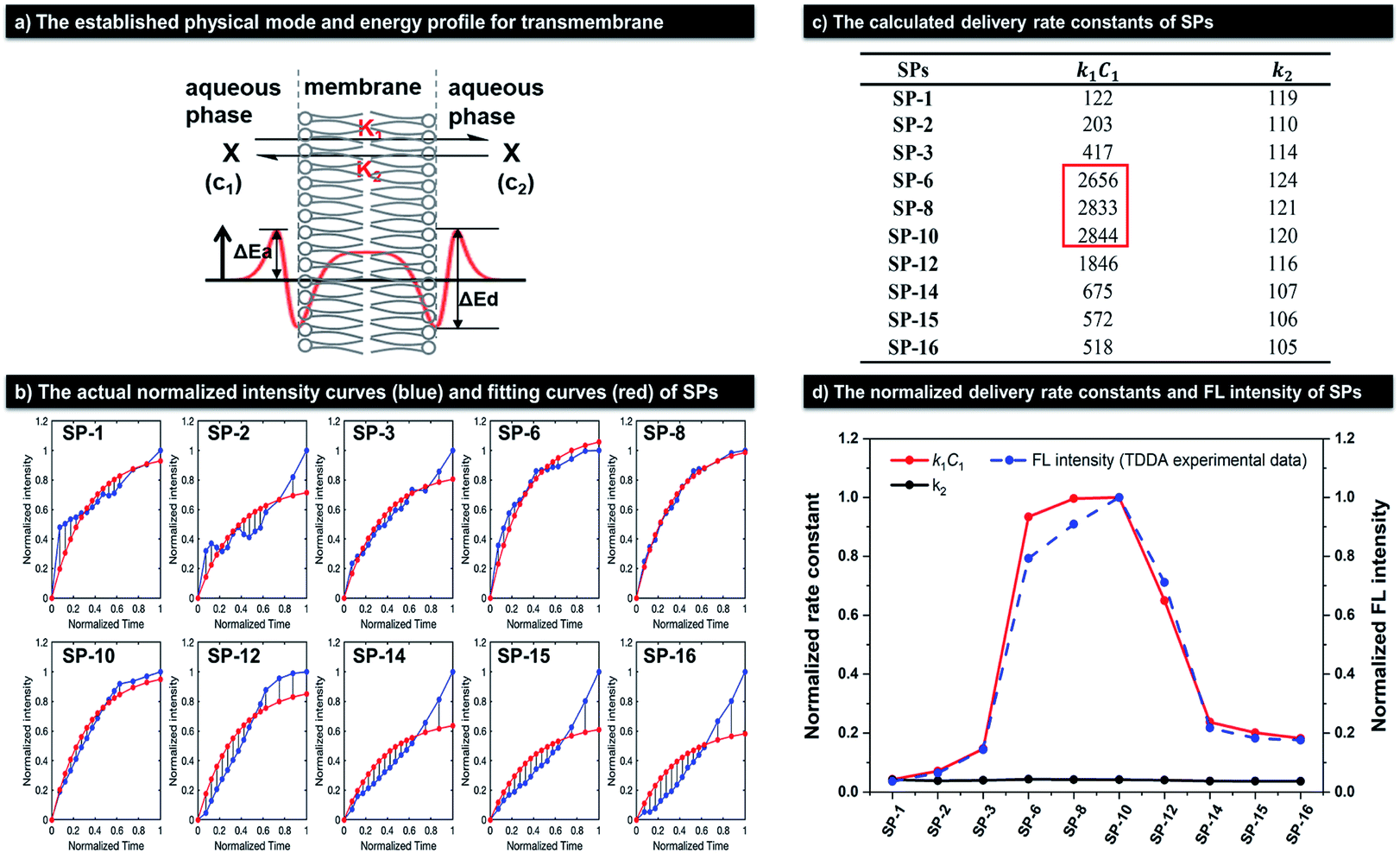
Simulated calculation of the delivery rate constants of SPs based on an established physical model
As mentioned above, the delivery manner of SP molecules into living cells conforms to the simple diffusion mechanism. Thus, a relevant physical model can be established for calculating their delivery rate constants. As shown in Fig. 5a, we assume that SPs are substance X, and its extracellular and intracellular concentrations are C1 and C2, respectively. As the extracellular volume is far larger than the intracellular one, the change of C1 can be considered negligible and C1 is close to the initial concentration C, while C2 will dynamically vary over time. Moreover, the rate constant of substance X from the extracellular aqueous medium to the intracellular space is denoted by k1, and that for the reverse process is k2. Because extracellular X appears in the unbound state while intracellular X is in the bound state in cells due to the definite interactions with intracellular entities, the values of k1 and k2 should be different. So, the rate equations can be established, as shown in eqn (1) and (2).| |  | (1) |
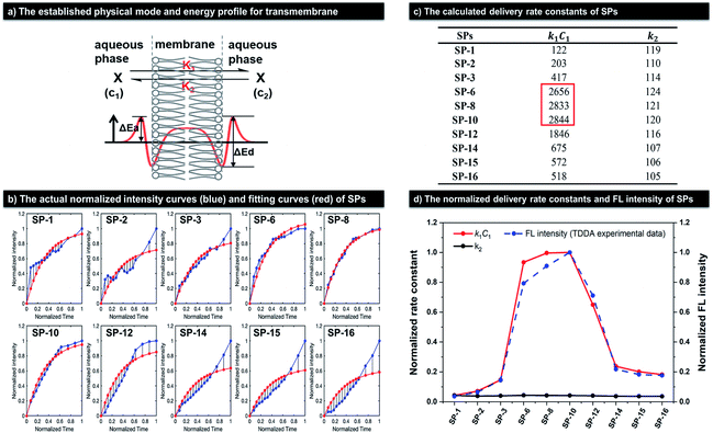 |
| | Fig. 5 The calculation of delivery rate constants of SPs in SiHa cells. (a) Top: the established physical model for the transport of SPs through the membrane; bottom: the corresponding activation energy profile. (b) The experimental intracellular normalized fluorescence intensity curves of SPs (blue) at different normalized times and the corresponding fitting curves (red). (c) The calculated delivery rate constants of SPs. (d) The normalized delivery rate constants and FL intensity at 25 min in the TDDA experiment (Fig. 3b) of SPs. | |
The final solution is given in eqn (3).
where
| |  | (4) |
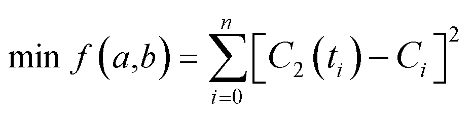
In order to obtain the values of a and b, we adopt the least squares fit model in eqn (5).
| |  | (5) |
where
C2(
ti) is the theoretical intracellular concentration of
SPs at time
ti and
Ci denotes the experimental intracellular one at time
ti.
Given the low intracellular concentration of SPs, their fluorescence intensity should be approximately proportional to the concentration.34,35 Thus, we can use fluorescence intensity (F) to replace the concentration terms in eqn (5). In order to ensure the fitting accuracy, normalization processing of fluorescence intensity and time terms needs to be carried out. Therefore, we finally obtain modified eqn (6).
| |  | (6) |
where

represents the theoretical normalized intracellular fluorescence intensity of
SPs at normalized time

and
Fi′ denotes the experimental normalized one at normalized time

from TDDA experiments in
Fig. 3c.
According to Fig. 3c, the corresponding normalized curves can be observed as blue lines in Fig. 5b. Thus, combining these experimental normalized data and eqn (6), we can obtain the final fitting curves (red lines in Fig. 5b) as well as parameters a and b by the gradient descent method.
As shown in Fig. 5b, the final fitting normalized lines (red lines) can well coincide with the experimental normalized curves (blue lines). And, the final values of rate constants (k1 and k2) have been obtained according to eqn (4), as shown in Fig. 5c and d. Because C1 is a known constant, we can compare k1 by comparing the values of k1C1. The k1C1 values of SPs with side-chain lengths of 6, 8, and 10 are dramatically larger than those of other SPs, up to 23-fold larger than that of SP-1. It is worth noting that the k2 values of SPs are all very low and close, which is mainly because once SPs enter the cell, they can rapidly accumulate in the mitochondria with large a MMP and thus rarely diffuse out of the cells. As a result, the k1C1 curves can represent the overall delivery rate changes of SPs, which can agree well with their experimental normalized FL intensity variations at 25 min in TDDA (Fig. 3b), as described by the red solid line and blue dotted line in Fig. 5d. Besides, similar results also have been obtained in MSC, as shown in Fig. S12b and S13.†SP-6, SP-8, and SP-10 have 70-fold larger k1C1 values than SP-1, but almost identical and low k2 values compared with other SPs. Notably, the k1C1 values in MSC are bigger than those in SiHa cells, which may be caused by the different cell types. Therefore, the simulated calculation of delivery rates in different cells also confirms that dyes with side-chains of suitable length can dramatically improve dye delivery.
The ultrafast delivery of dyes enables ultralow concentration (1 nM) cell imaging and deep-imaging in tissues and in vivo
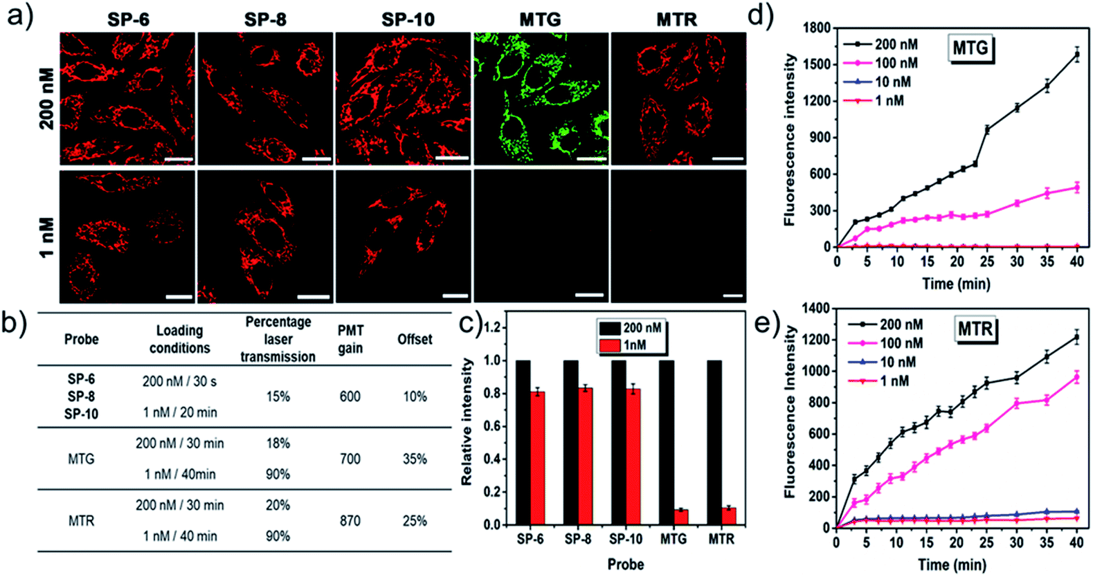
Better membrane permeability of dyes means the possibility of lower loading concentrations. As shown in Fig. 6, ultralow concentration mitochondrial staining (1 nM) within 20 min has been successfully realized with SP-6, SP-8, and SP-10, owing to their ultrafast delivery abilities. However, other SPs as well as commercial mitochondrial probes (MTG and MTR) cannot do this, as shown in Fig. S14–S20† and 6. Also, their ultralow concentration staining is not affected by the heterogeneity of the different cell types (Fig. S21†). Thus, SP-6, SP-8, and SP-10 with suitable side chains can serve as ideal probes for ultralow concentration loading.
 |
| | Fig. 6 Comparative LSCM images (a), corresponding imaging parameters (b), and relative fluorescence intensity (c) of SiHa cells stained with SP-6, SP-8, SP-10, and commercial mitochondrial probes (MTG and MTR) of different concentrations (200 nM and 1 nM). Time-dependent fluorescence intensity of SiHa cells stained with MTG (d) or MTR (e) of different concentrations (200 nM, 100 nM, 10 nM, and 1 nM). For SP-6, SP-8, and SP-10: λex = 473 nm, λem = 550–650 nm. For MTG: λex = 473 nm, λem = 500–600 nm. For MTR: λex = 543 nm, λem = 550–650 nm. Bar = 20 μm. | |
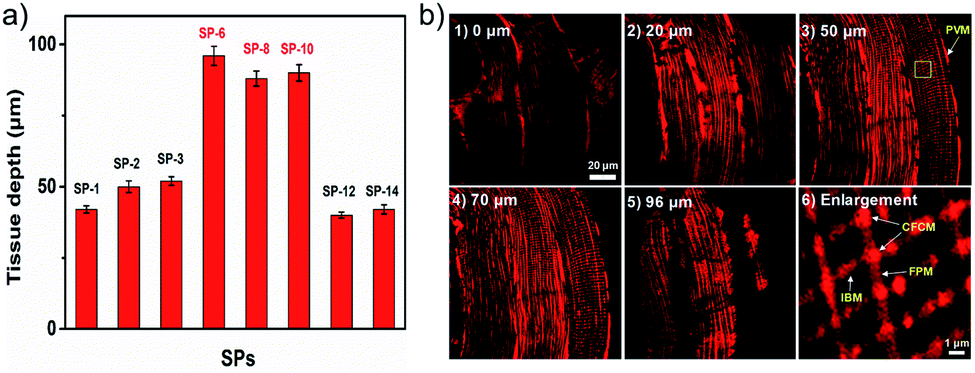
The ultrafast delivery is also favorable for easy penetration in thick biosamples. Given the good TPEF properties of SPs, a two-photon microscope (TPM) was used to test their penetration abilities. As shown in Fig. S22,†SPs can clearly image living cells under a TPM. Moreover, in rat skeletal muscle tissues, they show a dramatically increased imaging depth (up to 96 μm) compared to other SPs (Fig. 7a and S23†). Meanwhile, in turbid tissues stained with SP-6 (Fig. 7b), subtle and regular mitochondrial reticulum structures can be recognized unambiguously, and their four different forms36 also can be easily identified including perivascular mitochondria (PVM), I-band mitochondria (IBM), fiber parallel mitochondria (FPM) and cross fiber connection mitochondria (CFCM). In addition, they also can image living zebrafish up to an 86 μm depth (Fig. S24–S26†). Therefore, these probes with excellent delivery can be used to observe targets in tissues and in vivo, thus accelerating the understanding of intracellular structures in more complex and actual biological systems.
 |
| | Fig. 7 (a) The imaging depth contrast of SPs in skeletal muscle tissues. (b) TPEF tomography images of mitochondria in rat skeletal muscle tissues stained with SP-6 (10 μM, 30 min) at different depths ((1–5), 0–96 μm) and (6) the enlarged image of the yellow box in (3). λex = 900 nm, λem = 570–630 nm. | |
SCES enables conversion of impermeable dyes into permeable ones
Our group previously reported a carbazole-based double-salt dye (9E-BMVC1) with two methyls that could not penetrate living cells.19 Herein, we modify this dye using the SCES and synthesize a family of 9E-BMVC1 derivatives (9E-BMVCs) as shown in Fig. 8a. These new dyes show similar optical properties due to the identical fluorophore (Table S2†). By investigating their ability to enter cells and cellular locations (Fig. 8b and S27†), we found that 9E-BMVC1 cannot enter living cells; but when the CN reaches 3, the permeability of 9E-BMVC3 increases and its fluorescence signal can be detected within cells; when the CN changes to 6, 9E-BMVC6 rapidly enters the living cells and stains filamentous structures, which turn out to be mitochondria by co-localization with MTDR (up to 89% co-localization coefficient) as shown in Fig. S28;† when the CN continuously increases to 8 or larger, the corresponding dyes are blocked by the plasma membrane. Obviously, introducing a suitable length side-chain can even convert a membrane impermeable fluorescent dye into a permeable one.
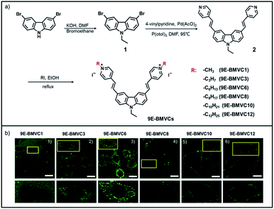 |
| | Fig. 8 (a) The molecular structures and synthetic route to 9E-BMVCs. (b) Top (1–6): LSCM images of SiHa cells stained with 5 μM 9E-BMVCs for 30 min without washing; bottom: the corresponding magnified images of the yellow boxes in (1–6). λex = 473 nm, λem = 500–600 nm. Bar = 20 μm. | |
In addition, some piecemeal reports also indirectly supported the applicability of the SCES we have proposed.37–39 For example, in a previous study, we found that the molecule LAD-1 with methyl always needs a longer time to enter cells in comparison to the molecule LAD with butyl.36 Moreover, commercial probes such as TMRM and TMRE with two methyls can cross the plasma membrane more rapidly than rhodamine 123 without an alkyl chain.37
Mechanism discussion on the relationship between the side-chain length and cellular delivery of dyes
We first interpret the effect of the side-chain length on cell permeability from the micro-viewpoint. According to the molecular transmembrane model, the desorption process is opposite to the adsorption.15–17 Thus, for efficient cellular delivery, there is a balance between the two contradictory requirements. In the adsorption process, the dye molecule needs to remove the hydration shell (energy barrier ΔEa in Fig. 5a) to get adsorbed into the hydrophobic interlayer space. In comparison, in the desorption process, it has to overcome the hydrophobic interaction (energy barrier ΔEd in Fig. 5a) with the lipid bilayer to enter the cells. As for short side-chain dyes, they have a strong hydration effect but weak hydrophobic interaction with the lipid bilayer, and so they are hard to adsorb but easy to desorb into the cytoplasm. Inversely, long side-chain dyes have a low hydration effect and strong hydrophobic interaction, which results in easy adsorption but difficult desorption. Thus, neither short nor long chains are favorable for cellular delivery, while an appropriate length side-chain can make both adsorption and desorption of dyes relatively easy, thus enabling efficient cellular delivery.
Macroscopically, changing the side-chain length mainly changed the logP of dyes. Thus, in order to further quantify the relationship between the side-chain length and cell permeability, the clogP values40 of SPs and 9E-BMVCs are presented in Tables S3 and S4.† For different compounds, the scope of clogP for efficient cellular delivery may be distinct, due to the substantial difference in the molecule structure. Concretely speaking, for SPs with a side-chain on one side, when the clogP is larger than 6.59, the dyes are stuck in the cell membrane and cannot enter the cells; when clogP is in the range of −1.34 to 6.06, the dyes can enter the cell. SP-6, SP-8, and SP-10 with clogP values of 1.30, 2.36, and 3.42, respectively, show excellent cell permeability. For 9E-BMVCs with a side-chain on two sides, when the clogP is lower than −2.79, the dyes cannot adsorb onto the membrane surface; in contrast, when clogP is beyond 4.62, the dyes are stuck in the membrane and cannot desorb from the inner membrane surface. That is, when the clogP is between −2.79 and 4.62, 9E-BMVC derivatives can enter the cells. According to the experimental results, 9E-BMVC6 with a clogP of 2.50 shows the best cell permeability. To sum up, we can draw a conclusion that when the clogP is in the range of 1.30–2.50, dyes should possess optimal cell permeability, which can serve as a guide for designing cell-permeant dyes.
Conclusions
In summary, we have demonstrated that a simple SCES can dramatically improve the delivery of organic dyes. Via an easy chemical modification, a series of SP dyes with side chains of different lengths were constructed. Their delivery behaviors were systematically studied in two different cell lines by cell imaging experiments and reasonably interpreted by building a diffusion model. According to the results, the cell delivery rate can be dramatically changed by simply tuning the side-chain length. The membrane permeability of SP-6–SP-10 probes bearing C6–C10 side-chains is above 76-fold higher than that of SP-1 with a C1 side-chain. Moreover, the cell delivery rate of fluorescent dyes first increases and then decreases with the extension of the side-chain length, and clogP values in the range of 1.30–2.50 should be optimal for the delivery into live cells. In particular, utilizing the side-chain engineering strategy, three fluorescent probes, SP-6, SP-8, and SP-10 have been constructed, which can light up mitochondria in live cells brightly with a loading concentration of 1 nM. To the best of our knowledge, this working concentration is much lower than that of all the reported and commercialized fluorescent probes currently. We expect that the side-chain engineering strategy can be an efficient guide for designing cell-permeant dyes, drugs, and other biological reagents.
Conflicts of interest
There are no conflicts to declare.
Acknowledgements
The study was supported by the National Natural Science Foundation of China (51773111, 21672130, 51273107, 51273175, and 51573158), Natural Science Foundation of Shandong Province, China (ZR2017ZC0227), Fundamental Research Funds of Shandong University (2017JC011 and 2018JC030), and MOE Key Laboratory of Macromolecular Synthesis and Functionalization, Zhejiang University (2018MSF03).
Notes and references
- D. J. Stephens and V. J. Allan, Science, 2003, 300(5616), 82–86 CrossRef CAS.
- J. A. Conchello and J. W. Lichtman, Nat. Methods, 2005, 2(12), 920–931 CrossRef CAS.
- I. Johnson, Histochem. J., 1998, 30(3), 123–140 CrossRef CAS PubMed.
- A. P. de Silva, H. Q. N. Gunaratne, T. Gunnlaugsson, A. J. M. Huxley, C. P. McCoy, J. T. Rademacher and T. E. Rice, Chem. Rev., 1997, 97(5), 1515–1566 CrossRef CAS PubMed.
- S. N. W. Toussaint, R. Calkins, S. Lee and B. W. Michel, J. Am. Chem. Soc., 2018, 140(41), 13151–13155 CrossRef CAS.
- K. A. Mix, J. E. Lomax and R. T. Raines, J. Am. Chem. Soc., 2017, 139(41), 14396–14398 CrossRef CAS.
- M. C. Morris, J. Depollier, J. Mery, F. Heitz and G. Divita, Nat. Biotechnol., 2001, 19(12), 1173–1176 CrossRef CAS PubMed.
- K. Johnsson, Nat. Chem. Biol., 2009, 5(2), 63–65 CrossRef CAS PubMed.
- P. L. Mcneil, Methods Cell Biol., 1988, 29, 153–173 CrossRef.
- K. Barber, R. R. Mala, M. P. Lambert, R. Qiu, R. C. Macdonald and W. L. Klein, Neurosci. Lett., 1996, 207(1), 17–20 CrossRef CAS.
- R. Y. Tsien, Nature, 1981, 290(5806), 527–528 CrossRef CAS PubMed.
- J. M. Gillis and P. Gailly, Biophys. J., 1994, 67(1), 476–477 CrossRef CAS PubMed.
- K. G. Morgan, Biophys. J., 1993, 65(2), 561–562 CrossRef CAS PubMed.
- S. Du, S. S. Liew, L. Li and S. Q. Yao, J. Am. Chem. Soc., 2018, 140(47), 15986–15996 CrossRef CAS PubMed.
- B. Ketterer, B. Neumcke and P. Läuger, J. Membr. Biol., 1971, 5(3), 225–245 CrossRef CAS.
- M. F. Ross, G. F. Kelso, F. H. Blaikie, A. M. James, H. M. Cochemé, A. Filipovska, T. D. Ros, T. R. Hurd, R. A. J. Smith and M. P. Murphy, Biochemistry, 2005, 70(2), 222–230 CAS.
- R. F. Flewelling and W. L. Hubbell, Biophys. J., 1986, 49(2), 531–540 CrossRef CAS PubMed.
-
A. A. Raoof, M. Gudipatim, D. C. Bibby, S. W. Reingold, S. Weinbach and A. Raoof, US pat., US2003036568-A1, 2003.
- N. Stevens, N. O'Connor, H. Vishwasrao, D. Samaroo, E. R. Kandel, D. L. Akins, C. M. Drain and N. J. Turro, J. Am. Chem. Soc., 2008, 130(18), 7182–7183 CrossRef CAS.
- Y. Zhang, J. Wang, P. Jia, X. Yu, H. Liu, X. Liu, N. Zhao and B. Huang, Org. Biomol. Chem., 2010, 8(20), 4582–4588 RSC.
- H. Zhou, J. Tang, L. Lv, N. Sun, J. Zhang, B. Chen, J. Mao, W. Zhang, J. Zhang and J. Zhou, Analyst, 2018, 143(10), 2390–2396 RSC.
- A. S. Klymchenko and R. Kreder, Chem. Biol., 2014, 21(1), 97–113 CrossRef CAS.
- M. Tian, Y. Liu, Y. Sun, R. Zhang, R. Feng, G. Zhang, L. Guo, X. Li, X. Yu, J. Z. Sun and X. He, Biomaterials, 2017, 120, 46–56 CrossRef CAS.
- L. Guo, R. Zhang, Y. Sun, M. Tian, G. Zhang, R. Feng, X. Li, X. Yu and X. He, Analyst, 2016, 141(11), 3228–3232 RSC.
- S. R. Marder, J. W. Perry and W. P. Schaefer, Science, 1989, 245(4918), 626–628 CrossRef CAS.
- G. S. He, J. D. Bhawalkar, C. F. Zhao, C. K. Park and P. N. Prasad, Appl. Phys. Lett., 1996, 68(25), 3549–3551 CrossRef CAS.
- G. S. He, Y. Cui, J. D. Bhawalkar, P. N. Prasad and D. D. Bhawalkar, Opt. Commun., 1997, 133(1), 175–179 CrossRef CAS.
- G. S. He, L. Yuan, Y. Cui, M. Li and P. N. Prasad, J. Appl. Phys., 1997, 81(6), 2529–2537 CrossRef CAS.
- Y. Chen, L. Qiao, L. Ji and H. Chao, Biomaterials, 2014, 35(1), 2–13 CrossRef CAS.
- S. W. Perry, J. P. Norman, J. Barbieri, E. B. Brown and H. A. Gelbard, BioTechniques, 2011, 50(2), 98–115 CrossRef CAS.
- M. Poot, Y. Z. Zhang, J. A. KrãMer, K. S. Wells, L. J. Jones, D. K. Hanzel, A. G. Lugade, V. L. Singer and R. P. Haugland, J. Histochem. Cytochem., 1996, 44(12), 1363–1372 CrossRef CAS.
- R. J. Oliveira, P. C. Whitford, J. Chahine, V. B. P. Leite and J. Wang, Methods, 2010, 52(1), 91–98 CrossRef CAS.
- S. Wakayama, S. Kiyonaka, I. Arai, W. Kakegawa, S. Matsuda, K. Ibata, Y. L. Nemoto, A. Kusumi, M. Yuzaki and I. Hamachi, Nat. Commun., 2017, 8, 14850 CrossRef CAS.
- H. Y. Yuan, Y. M. Huang, J. D. Yang, Y. Guo, X. Q. Zeng, S. Zhou, J. W. Cheng and Y. H. Zhang, Spectrochim. Acta, Part A, 2018, 200, 330–338 CrossRef CAS.
- M. Ge, P. Bai, M. Chen, J. Tian, J. Hu, X. Zhi, H. Yin and J. Yin, Anal. Bioanal. Chem., 2018, 410(9), 2413–2421 CrossRef CAS.
- B. Glancy, L. M. Hartnell, D. Malide, Z. X. Yu, C. A. Combs, P. S. Connelly, S. Subramaniam and R. S. Balaban, Nature, 2015, 523(7562), 617–620 CrossRef CAS.
- X. Li, M. Tian, G. Zhang, R. Zhang, R. Feng, L. Guo, X. Yu, N. Zhao and X. He, Anal. Chem., 2017, 89(6), 3335–3344 CrossRef CAS PubMed.
-
Molecular Probes™ Handbook, 11th edn, 2011 Search PubMed.
- N. Li, Y. Y. Liu, Y. Li, J. B. Zhuang, R. R. Cui, Q. Gong, N. Zhao and B. Z. Tang, ACS Appl. Mater. Interfaces, 2018, 10(28), 24249–24257 CrossRef CAS PubMed.
- M. Ishikawa and Y. Hashimoto, J. Med. Chem., 2011, 54, 1539–1554 CrossRef CAS PubMed.
Footnote |
| † Electronic supplementary information (ESI) available. CCDC 1904261–1904263. For ESI and crystallographic data in CIF or other electronic format see DOI: 10.1039/c9sc05875c |
|
| This journal is © The Royal Society of Chemistry 2020 |
Click here to see how this site uses Cookies. View our privacy policy here. 
 Open Access Article
 This Open Access Article is licensed under a Creative Commons Attribution-Non Commercial 3.0 Unported Licence
 *a,
Jing Zhi
Sun
*a,
Jing Zhi
Sun


 represents the theoretical normalized intracellular fluorescence intensity of SPs at normalized time
  and Fi′ denotes the experimental normalized one at normalized time
  from TDDA experiments in Fig. 3c.