Insights into membrane-separated organic electrosynthesis: the case of adiponitrile electrochemical production†
Daniela E.
Blanco
,
Purnima A.
Prasad
,
Kaylee
Dunningan
and
Miguel A.
Modestino
 *
*
New York University, Tandon School of Engineering, 6 Metrotech Center, Brooklyn, NY 11201, USA. E-mail: modestino@nyu.edu
First published on 13th November 2019
Abstract
Organic electrosynthetic processes are key players in the integration of renewable energy in chemical manufacturing, but face important challenges in selectivity and energy efficiency. Although membrane-separated flow reactors can help address these issues, a deeper understanding of membrane behavior in organic-containing electrolytes is required. We evaluate the effect of organic reactants on the conductivity and permeability of one cation exchange membrane (Nafion 117) and two anion exchange membranes (Sustainion and Fumasep FAB), to later assess the advantages of their implementation in flow reactors for the electrohydrodimerization of acrylonitrile to adiponitrile – the largest organic electrosynthesis in industry. The presence of organic molecules led to important losses in membrane conductivity, however no significant contribution to reactor overpotential was observed from their implementation in membrane-separated reactors. Furthermore, permeabilities between 0.4–1.2 × 10⁻⁶ cm2 s−1 towards organic molecules led to low crossover of organics and improved reactor selectivity. Undivided reactors yielded selectivities as high as 48% (40 mA cm−2 and 4 V), while selectivities of 77% (20 mA cm−2 and 2.7 V) and 81% (40 mA cm−2 and 3 V) were obtained with Nafion and Sustainion-separated reactors, respectively. The demonstrated improvement in energy efficiency for continuous organic electrosynthetic processes makes the insights from this work a significant step in the development of sustainable electrochemical manufacturing processes.
Introduction
Membrane-separated electrochemical reactors have the potential to improve chemical manufacturing practices as they can lead to significant enhancements in energy conversion efficiency and reductions in manufacturing costs. In these reactors, cathodic and anodic compartments are physically separated with ion exchange membranes that (i) help prevent parasitic redox reactions of products and reactants in opposite chambers, (ii) allow the independent optimization of cathodic/anodic reaction conditions, and (iii) can reduce the interelectrode distance in an overall effort to lower energy losses. Additionally, as reduction and oxidation products are separated, downstream separation costs can be reduced.1–4 Given these advantages, membrane-separated electrochemical reactors will play an important role in the transition from heat-powered to electricity-driven chemical processes, helping to accelerate the electrification of the chemical industry. The implementation of such electrochemical processes will in turn result in sustainability improvements, as they will facilitate the integration of renewable electricity sources with chemical manufacturing, improve the energy efficiency of existing production routes, enable the operation of reactors under mild temperature and pressure conditions, and utilize environmentally benign aqueous electrolytes.2,5–7Membrane-based flow reactors have been previously implemented for the improvement of safety and efficiency in multiphase organocatalysis.8–13 In electrochemistry, while the use of membranes has been extensively investigated in inorganic processes (e.g. chloro-alkali and water splitting14–25), their use in organic electrosynthetic applications has remained relatively unexplored, leaving a knowledge gap regarding the effect of organic molecules on membrane properties and performance. Ion exchange membranes consist of polymer backbones with ion-containing side groups, often resulting in microphase-separated structures composed of ionic and non-ionic domains.26,27 Their performance is commonly defined by ionic conductivity, reactant permeability, and durability. These properties depend on the chemical structure of the polymer, volume fraction of the ionic domains, and the nature of the ionic carrier,28 but could be affected by interaction with organic molecules. Among the most commonly used separators, cation exchange membranes (CEM) are designed to conduct cations while acting as electronic insulators and barriers to neutral molecules and anions.29 Perfluorinated sulfonic acid (PFSA) membranes (e.g. Nafion®) are the most commonly used CEMs given their robustness and high ionic conductivity. Sulfonated styrenes, polyimides, and arylene ethers, among others, have been studied as alternative polymeric membranes,30–33 but their stability generally sets them behind perfluorinated polymers.
Conversely, anion exchange membranes (AEM) are designed for the selective transport of anions as they contain positively-charged groups fixed to the polymeric matrix. Fluorinated hydrocarbons, polyketones, polyethers, and poly(ether ketones) constitute common AEM backbones.34–38 While imidazolium and quaternary amines have been the most extensively used ion-exchange groups,34,39,40 nitrogen free (e.g. phosphonium) and other charged groups have also been studied.39 The kinetics of certain reactions, such as oxygen evolution, are facilitated under alkaline conditions and allow the use of less expensive electrocatalysts, such as nickel (Ni).41 However, avoiding the degradation of the ionic groups under alkaline conditions – which often occurs through nucleophilic displacement, Hoffman elimination, or ring opening reactions27 – has been a challenge for the scientific community.42
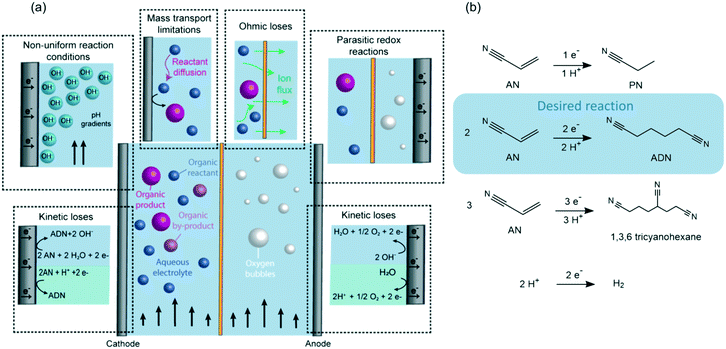
As shown in Fig. 1, maintaining high selectivity and energy conversion efficiencies in organic electrosynthesis is challenging due to (i) the large overpotentials required for the reactions, (ii) the decreased conductivity of electrolytes when organic reactants are present, and (iii) mass transport limitations that can lower the conversion rates of organic reactants due to their slow diffusion to the electrical double layer (EDL). Furthermore, in the case of flow reactors, faradaic efficiencies can also be affected by (i) the non-uniform reaction conditions generated throughout the flow path (i.e., concentration and pH gradients), or by (ii) the crossover of reactants and products between the anodic and cathodic chambers leading to undesired redox reactions.
Examples of the implementation of membranes in organic electrochemical devices include methanol fuel cells,43,44 adiponitrile (ADN) electrosynthesis,45 hydrogenation of olefins,46 reduction of nitrobenzene,47 organic carboxilations,48 and oxidation of cyclic alcohols and furan.49,50 Out of these, the electrosynthesis of ADN is the largest-volume organic electrochemical transformation – accounting for >500 K tons of ADN production annually. In our previous studies on the electrohydrodimerization of AN, faradaic efficiencies between 60–83% were demonstrated in a membrane-separated batch reactor at low conversions (i.e. <20%).51,52 Available sulfonated polystyrene/divynilbenzene polymer membranes were first tested on ADN electrosynthesis in 1962, but challenges with short membrane lifetime and high cell potentials led to the implementation of undivided electrochemical reactors shortly after.53–57 Significant advances on ion-conducting membranes have been achieved since then and may lead to improved performance for organic electrosynthetic processes.
Motivated by the possible enhancement in energy conversion efficiencies with the incorporation of membranes in organic electrosynthetic reactors, this work systematically explores the effect of organic-containing electrolytes on some of the most common commercially available CEM (Nafion) and AEMs (Sustainion and Fumasep FAB). Using the electrosynthesis of ADN as a model reaction, we establish relationships between the electrolyte composition, membrane internal structure, and their transport properties. The insights gained on this study can facilitate the design of membrane-separated electrochemical reactors that maximize energy efficiency and can significantly advance green chemical manufacturing of organic products.
Results and discussion
Undivided flow reactors
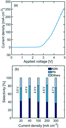
Undivided flow reactors are often implemented in electrochemical processes to circumvent challenges associated with high ionic resistance and low durability of membranes. However, undivided reactor selectivity can be strongly affected by non-uniform conditions and product crossover in the system. Fig. 2(a) shows the polarization curve of an undivided flow cell, depicting a linear behaviour at high current densities (i.e., >100 mA cm−2) characteristic of ohmic-limited electrochemical processes. Additionally, large activation overpotentials are observed (i.e., onset potential at >2.5 V), indicating large kinetic loses in the reaction. Fig. 2(b) shows the measured reactor selectivity – determined from the product distribution of the reactor outlet stream – for ADN, propionitrile (PN), and other by-products (e.g., hydrogen and AN oligomers). The results show that as current density increases, the system approaches mass transport limitations. As the reactant is consumed faster, a lower local reactant concentration is found in the EDL, favoring both the formation of PN, which requires only one AN equivalent, and the hydrogen evolution reaction, instead of ADN formation (requires 2 AN equivalents).52The highest selectivity reached with the undivided flow reactor was 48% at 40 mA cm−2 and 4.0 V cell potential, which is significantly lower than the 83% reached in a membrane-separated batch reactor. In spite of the advantages offered by undivided flow reactors, our results demonstrate the challenges in obtaining high performance in organic electrosynthesis. These performance limitations could arise from the slow charge transport in the electrolyte, large kinetic losses, non-uniform conditions throughout the electrode surface, and possible oxidation of organic species at the anode. Membranes could help address some of these issues as they enable the use of organic-free anolytes (e.g., sulfuric acid or sodium hydroxide) with higher conductivity and improved oxygen evolution kinetics. Moreover, membranes with low permeability towards organic molecules can prevent their crossover and subsequent undesired oxidation in the anodic compartment. To better assess the potential of membrane-separated organic electrosynthetic reactors, the following subsections explore the behaviour and effect of some of the most widely used cation (Nafion) and anion (Sustainion and Fumasep FAB) exchange membranes in the reactor configurations shown in Fig. 3.
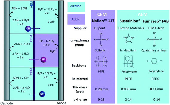 | ||
| Fig. 3 Tested reactor configurations for ADN electrochemical production with membrane-based reactors, and main characteristics of the CEM and AEMs tested. | ||
CEMs: Nafion 117
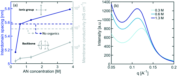
Nafion CEMs are the most commonly used membranes for electrochemical devices, providing the best balance between high ionic conductivity and stability. Although Nafion has been extensively studied in water electrolysis, hydrogen fuel cells, and chloro-alkali applications, its behaviour in organic electrosynthesis reactors is unknown. Organic molecules present in the electrolyte can interact with Nafion's ionic domains, altering its internal microstructure and transport properties. As shown in Fig. 4(a), exposing Nafion to typical electrolyte compositions for ADN electrosynthesis results in a significant loss in ionic conductivity (i.e., up to a ∼1000× decrease for dilute concentrations of organics). This loss in conductivity can be caused by changes in the size of ionic domains, the nature and mobility of charge carriers, and the composition of the electrolyte within the ionic domains of the membrane.To understand how organics affect the internal structure of Nafion, SAXS measurements were performed at varying concentrations of AN in the electrolyte. The results presented in Fig. 4(a) demonstrate a significant decrease in ionic domain size at dilute concentrations of organics, followed by a monotonic expansion of these domains as the concentration increases – similar to the trend observed for conductivity. This behaviour suggests that, as organics are added to the electrolyte, water is expelled from the ionic channels of Nafion to compensate for the changes in the chemical potential of the surrounding electrolyte. However, as the concentration of organics increases, their presence inside of the membrane also increases, causing an expansion of the ionomer domains. It is also further consistent with the increase in scattering intensity observed in the SAXS patterns presented in Fig. 4(b). This is indicative of an increase in scattering contrast between the PTFE matrix and the ionomer domains likely caused by the higher concentration of organics in these domains. In order to further validate this hypothesis, we demonstrated that the solubility of AN in PTFE is less than 3% of the total solubility in Nafion, suggesting that organic molecules would preferentially enter the ionic domains of the polymer over the hydrophobic matrix. This expansion of Nafion's ionic domains can lead to the observed increase in ionic conductivity.58–60
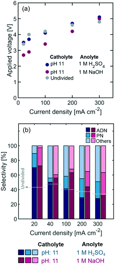
In addition to the effect of organic molecules on Nafion conductivity, the composition and pH of the electrolyte plays a significant role on the selectivity of the electrode reactions. An added advantage of incorporating membranes in reactors is the possibility to operate the cell with different compositions in the catholyte and anolyte. To demonstrate this advantage, we operated the anodic compartment of the cell with 1 M sulfuric acid (H2SO4) and an iridium oxide (IrOx) electrode or 1 M sodium hydroxide (NaOH) and a nickel (Ni) electrode. These electrocatalysts were chosen to favor the oxygen evolution reaction (OER) kinetics under each pH condition.61,62 The OER reaction is favored under strong basic conditions since the standard reaction potential is 0.8 V in 1 M NaOH vs. 1.23 V in 1 M H2SO4, and low activation overpotential can be achieved with Ni-based catalysts.61 Although H2SO4 has a higher conductivity than the organic-containing catholyte (Table 1) – which translates into a lower ohmic resistance for the electrolyte – the NaOH anolyte has a lower conductivity than the organic-containing catholyte due to the lower concentration of supporting ions.
As shown in Fig. 5, the selectivity towards ADN is slightly higher when basic anolytes are used and sodium ions are the main charge carriers (Table 1). Alkaline anolytes ensure that the pH of the cathodic chamber remains high as the cell operates, while under acidic anolytes protons migrating across the Nafion membrane (see Fig. 3) can lower the pH in the catholyte and decrease selectivity towards ADN. On the other hand, a decrease in power requirements could be expected from the use of aqueous conductive anolytes – instead of organic containing ones – and the use of electrolyte pH conditions that reduce energy losses. The results show an important decrease in overpotential with the use of NaOH anolytes, suggesting that alkaline anodic environments can significantly lower the thermodynamic potential for the reaction and, in turn, the cell power requirement.
| Electrolyte | Ion mobility [cm2 V−1 s−1] | Transference numbers | Electrolyte conductivity [S m−1] |
|---|---|---|---|
| Catholyte pH 11 | Na+: 5.19 × 10⁻⁴OH−: 2.05 × 10⁻³H+: 3.62 × 10⁻³PO43−: 2.07 × 10⁻³TBA: 2.02 × 10⁻⁴SO42−: 4.14 × 10⁻⁴ | Na + : 0.203OH−: 5.25 × 10⁻⁴H+: 9.27 × 10⁻¹²PO43−: 0.796TBA: 0.001 | 37.65 |
| 1 M H2SO4 pH 0 | H + : 0.89SO 4 2− : 0.11 | 77.85 | |
| 1 M NaOH pH 14 | Na + : 0.20OH − : 0.80 | 24.78 |
Membranes can also help reduce undesired oxidation of organic reactants and products. The permeability of relevant organic molecules for ADN electrosynthesis in Nafion is presented in Table 2. Under operating conditions, these permeabilities result in a maximum crossover flux of 2.5 × 10⁻⁹, 7 × 10⁻¹⁰, and 2 × 10⁻⁹ mol cm−2 s−1 for AN, ADN and PN, respectively, which is <1% of the reaction rate at the cathode surface. The decrease in crossover, together with the gains on ion-conductivity and reaction kinetics, results in a significant improvement in selectivity (i.e., a maximum of 77% at 20 mA cm−2 and 2.6 V) for Nafion-separated flow reactors in comparison to undivided cells.
| Permeability [×10−6 cm2 s−1] | Solubility | Diffusivity [×10−6 cm2 s−1] | |
|---|---|---|---|
| Nafion | |||
| AN | 1.20 ± 0.05 | 1.10 ± 0.03 | 1.09 ± 0.07 |
| PN | 1.01 ± 0.05 | 0.95 ± 0.03 | 1.06 ± 0.07 |
| ADN | 0.82 ± 0.07 | 1.12 ± 0.03 | 0.73 ± 0.08 |
| Sustainion | |||
| AN | 0.61 ± 0.03 | 0.10 ± 0.03 | 6.1 ± 3 |
| PN | 0.70 ± 0.03 | 0.11 ± 0.03 | 7.0 ± 2 |
| ADN | 0.40 ± 0.05 | 2.61 ± 0.08 | 0.15 ± 0.03 |
| Fumasep FAB | |||
| AN | 0.53 ± 0.04 | 0.40 ± 0.05 | 1.3 ± 0.3 |
| PN | 0.53 ± 0.04 | 0.39 ± 0.05 | 1.3 ± 0.3 |
| ADN | 0.47 ± 0.02 | 1.90 ± 0.08 | 0.25 ± 0.1 |
AEMs: Sustainion and Fumasep FAB
Emerging AEMs are good membrane candidates for organic electro-reductions as they can support the migration of OH− ions and lower the ohmic resistance of the cell. As in the case of CEMs, the interaction of organic molecules with AEMs can also limit their transport and structural properties. To evaluate the potential of AEMs in ADN electrosynthesis, two state-of-the-art AEMs were studied: Sustainion, a membrane composed of a polystyrene backbone with pendant imidazolium ionic groups, and Fumasep FAB, composed of a polyarylene matrix with quaternary amine substituents.Fig. 6 shows the effect of AN concentration on AEM membrane conductivity. The results for both AEMs follow a similar trend to that of Nafion, suggesting that ionic pathways shrink initially at low AN concentration, but are expanded as organics enter the ionic domain at higher concentrations. SAXS patterns of AEMs did not exhibit any significant scattering features due to the lack of coherence of the ionic domains, which prevented us from performing a detailed analysis on changes in their internal structure.
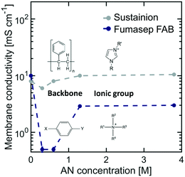 | ||
| Fig. 6 Effect of AN concentration on membrane conductivity for Sustainion and Fumasep FAB AEMs at 25 °C. The electrolyte contained 0.5 M Na3PO4, 0.02 M TBA hydroxide, and 0.03 M EDTA. | ||
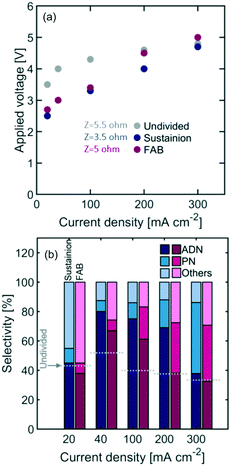
Fig. 7 shows the reactor selectivity obtained with AEM-based flow reactors. Although membranes introduce an additional resistance to ionic flux, the overall cell voltage is lower for both AEMs when compared to the undivided configuration. This is likely due to the improved OER kinetics under the 1 M NaOH anolyte implemented. Overall, Sustainion led to a lower cell resistance than the FAB membrane, which is likely the result of Sustainion's lower thickness (i.e. 0.088 mm) and higher ionic conductivity in organic containing electrolytes.
The permeability of organic species in AEMs was low (see Table 2), which helps explain the improved selectivity with respect to undivided reactors. The highest selectivity – 81% – was observed with Sustainion at 40 mA cm−2 and 3.0 V applied voltage (see Table 3 for summary of performance improvements with membrane-based reactors).
| Membrane | Reactor selectivity | Current density | Cell potential |
|---|---|---|---|
| Batch51 | 83% | 26 mA cm−2 | 2.6 V vs. SHE |
| Undivided – flow | 48 % | 40 mA cm−2 | 3.0 V |
| Sustainion – flow | 81 % | 40 mA cm−2 | 3.0 V |
| Nafion 117 – flow | 77% | 20 mA cm−2 | 2.7 V |
Conclusions
The use of membrane-separated reactors for organic electrosynthesis was studied using the electrohydrodimerization of AN to ADN as a model reaction. Undivided flow reactors exhibited charge transport limitations and parasitic redox reactions leading to 48% reactor selectivity. To better understand the potential for the implementation of membranes in flow reactors, the effects of organic containing electrolytes were studied on relevant membrane properties. In the case of Nafion membranes, the addition of dilute organic concentrations leads to a decrease in the size of ion-conducting domains, which results in a drop in conductivity. As the concentration of organics increases, these domains are expanded, increasing membrane conductivity. The two AEMs tested, Sustainion and Fumasep FAB, display a similar trend on conductivity, with Sustainion having the weakest conductivity dependence on organic concentration.Membrane ohmic resistance did not contribute significantly to the overpotential of reactors. Using alkaline anolytes provided a clear advantage to membrane-separated reactors by improving the OER kinetics and lowering the thermodynamic requirement for the reaction, ultimately lowering the cell power requirements by >20% at 40 mA cm−2 compared with undivided flow reactors. Permeability coefficients in the range of 0.4–1.2 × 10⁻⁶ cm2 s−1 and alkaline anolytes led to lower organic crossover, which improved reactor selectivities to 77% (at 20 mA cm−2 and 2.7 V applied voltage) and 81% (at 40 mA cm−2 and 3 V) with Nafion and Sustainion, respectively.
This study revealed that membrane permeability, conductivity, and electrolyte pH are significant drivers for energy efficiency and selectivity in membrane-separated reactors, and that membrane properties can be severely affected by the presence of organic reactants in the electrolyte. The insights provided in this study are an important step towards developing design guidelines for continuous organic electrosynthetic processes which will contribute to the deployment of scalable and sustainable manufacturing in the chemical industry.
Experimental
Materials
All chemicals were acquired from Sigma-Aldrich, including sodium phosphate, tetrabutylammonium (TBA) hydroxide, ethylenediaminetetraacetic acid (EDTA) disodium salt, acrylonitrile (AN), adiponitrile (ADN), propionitrile (PN), sulfuric acid, and sodium hydroxide. Unless specified differently, the electrolyte contained 0.5 M Na3PO4, 0.02 M TBA hydroxide, 0.03 M EDTA, and 0.6 M AN.Nafion™ 117 membranes were acquired from the Nafion Store, Sustainion® X-37 50 grade reinforced with PTFE AEM from Dioxide Materials, and Fumasep® FAB AEM from the Fuel Cell Store. They were subsequently pre-treated by stirring in boiling water for 1 hour (Nafion™ 117) and soaking in 1 M KOH (AEM Sustainion®) or 1 M NaCl (Fumasep® FAB) for 24 hours. They were then equilibrated in the organic electrolyte solution for 1 hour. Membranes were considered fully equilibrated after 40 minutes in the electrolyte solution, as no significant changes in membrane conductivity were measured (see Fig. S1 in the ESI†). A summary of the membranes tested and their characteristics is presented in Fig. 3.
Membrane characterization
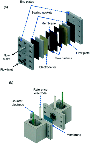 | ||
| Fig. 8 (a) Electrochemical flow cell for a two-electrode setup, showing flow inlet and outlet together with main plates and gaskets used for cell assembling (see S2 in the ESI† for dimensions). The membrane separators are introduced between two patterned gaskets and the electrode foils are placed next to metallic flow plates that also serve as electrical connections to the external energy source during electrochemical measurements. (b) Experimental four-electrode setup, showing the two reference electrodes and counter electrodes used during EIS measurements. A membrane separated the two chambers and is sealed between two o-rings. | ||
A constant flowrate of 0.81 mL min−1 for each chamber was imposed with an IDEX Reglo ICC peristaltic pump and 2.54 mm inner diameter (ID) viton tubing. Each experiment was carried out in two separate trials, and a total of four samples were taken to ensure reproducibility in the experiments. Membranes were stabilized in the flow system for 40 minutes prior to sample collection.
Membrane permeability was calculated with the measured concentration of organic species in the cathodic and anodic outlet streams. These were considered steady state concentration profiles, and diffusion limitations in the liquid electrolyte were considered negligible, given that no significant variations were measured on the outlet streams as a function of flow rates (see Fig. S3 in the ESI†). The species' flux and steady-state concentration gradient across the membrane were used to calculate membrane permeability, according to:
 the flux of species k through the membrane. The concentration gradient was assumed to be linear across the membrane and calculated from the bulk concentrations in both chambers.
To obtain values of Sk, 1 cm2 of each pre-treated membrane was soaked in catholyte solution for 40 minutes. After careful rinse, the adsorbed organics were extracted by soaking the membrane in 5 mL of toluene for 10 minutes. Longer times and larger toluene volumes did not lead to significant variations of Sk.
Ag/AgCl (4 M KCl) reference electrodes from Pine Research Instrumentation and 100 mesh platinum mesh (Alfa Aesar) counter electrodes were used for all experiments. All membranes were equilibrated in the respective electrolyte for 40 minutes before reporting conductivity values and membrane conductivity (σ) was calculated using wet membrane thickness (δ, measured with a caliper), membrane resistance (R) from EIS experiments, and the exposed membrane area (A) to electrolyte solution, following:
Small angle X-ray scattering (SAXS)
Pre-treated Nafion N117 samples were placed in a sealed sample Teflon holder containing the electrolyte solution and equipped with X-ray transparent Kapton windows (design and geometry in the ESI†). The samples were equilibrated in solution for 40 minutes before measurements were performed. SAXS was performed at beamline CMS at the National Synchrotron Light Source II (NSLSII) at Brookhaven National Laboratory. The X-ray energy was 13.5 keV with 0.7% resolution. Two-dimensional scattering patterns were collected using a 2D Dectris Pilatus 2M charge-coupled device (CCD) detector (172 μm × 172 μm pixel size) at a sample-detector distance of 1.98 meters and a 30 second exposure time. Interdomain spacing (d) was calculated from the maximum scattering wave vector (d = 2π/qmax), and all scattering data was corrected for the electrolyte solution and Kapton windows.Electrochemical flow cell characterization
The electrochemical flow cell depicted in Fig. 8(a) was also used to measure the reactor selectivity in the electrohydrodimerization of AN to ADN in undivided and divided flow reactors. A two-electrode setup was used with a cadmium foil (American Elements) as the cathode for AN reduction with the same flow rate described above. A nickel foil (American Elements) and a 0.035′′ mesh coated with iridium-based Futura coating from De Nora Electrode Technologies were used under alkaline and acidic anolyte conditions, respectively, as anodes that facilitate the oxygen evolution reaction.Cyclic voltammetry (CV) experiments, electrochemical impedance spectroscopy (EIS), and chronopotentiometry (CP) techniques were performed using a BioLogic VSP-300 potentiostat. CV experiments were carried out from 0 to 4 V with a scan rate of 50 mV s−1. Prior to experiments, the cadmium electrode surface was operated at 40 mA cm−2 for 10–12 hours with the catholyte solution to ensure stable operation. Measurements were performed at room temperature and electrolyte pH was measured with a B30PCI pH meter from VWR.
Chemical analysis
Liquid–liquid extraction with toluene was used to separate the organic molecules from the aqueous electrolyte. The organic phase was then analyzed in an Agilent 7890B gas chromatographer and 5977B mass spectrometer. Component identification and quantification were performed using calibration curves for AN, PN, and ADN. Faraday's law was used to calculate the partial current of each species (jk):where nk corresponds to the moles of species k consumed or produced, z to number of electrons involved in the reaction, j to the current in A, t to the time of reaction in s, A the area of the electrode and F to Faraday's constant. The reactor selectivity reported throughout the study is calculated as the ratio between jk (from collected product stream) and the total current density.
Conflicts of interest
DEB and MAM are co-founders of and hold a financial interest in Sunthetics Inc., a start-up company operating in the sustainable chemical manufacturing space.Acknowledgements
The authors would like to acknowledge the support of Dr. Brandon Fowler at the Mass Spectrometry Core Facility of Columbia University. They thank Esther Tsai and Ruipeng Li for their assistance performing experiments at beamline CMS of Brookhaven National Laboratory. They also acknowledge the financial support provided by H&M Foundation through the Global Change Award and from New York University, Tandon School of Engineering, through the MAM startup fund.References
- I. Merino-Garcia, E. Alvarez-Guerra, J. Albo and A. Irabien, Chem. Eng. J., 2016, 305, 104–120 CrossRef CAS.
- D. E. Blanco and M. A. Modestino, Trends Chem., 2019, 1(1), 8–10 CrossRef.
- D. M. Weekes, D. A. Salvatore, A. Reyes, A. Huang and C. P. Berlinguette, Acc. Chem. Res., 2018, 51, 910–918 CrossRef CAS.
- K. Subramanian, K. Asokan, D. Jeevarathinam and M. Chandrasekaran, J. Appl. Electrochem., 2007, 37, 255–260 CrossRef CAS.
- A. Wiebe, T. Gieshoff, S. Möhle, E. Rodrigo, M. Zirbes and S. R. Waldvogel, Angew. Chem., Int. Ed., 2018, 57, 5594–5619 CrossRef CAS PubMed.
- M. J. Orella, Y. Román-Leshkov and F. R. Brushett, Curr. Opin. Chem. Eng., 2018, 20, 159–167 CrossRef.
- G. Botte, Electrochemical Manufacturing in the Chemical Industry, 2014 Search PubMed.
- P. Kisszekelyi, A. Alammar, J. Kupai, P. Huszthy, J. Barabas, T. Holtzl, L. Szente, C. Bawn, R. Adams and G. Szekely, J. Catal., 2019, 371, 255–261 CrossRef CAS.
- L. Peeva, J. Da Silva Burgal, Z. Heckenast, F. Brazy, F. Cazenave and A. Livingston, Angew. Chem., 2016, 128, 13774–13777 CrossRef.
- Y. Mo, J. Imbrogno, H. Zhang and K. F. Jensen, Green Chem., 2018, 20, 3867–3874 RSC.
- A. Constantinou, G. Wu, A. Corredera, P. Ellis, D. Bethell, G. J. Hutchings, S. Kuhn and A. Gavriilidis, Org. Process Res. Dev., 2015, 19, 1973–1979 CrossRef CAS.
- M. O'Brien, N. Taylor, A. Polyzos, I. R. Baxendale and S. V. Ley, Chem. Sci., 2011, 2, 1250–1257 RSC.
- A. Polyzos, M. O'Brien, T. P. Petersen, I. R. Baxendale and S. V. Ley, Angew. Chem., Int. Ed., 2011, 50, 1190–1193 CrossRef CAS PubMed.
- J. W. Ager, M. R. Shaner, K. A. Walczak, I. D. Sharp and S. Ardo, Energy Environ. Sci., 2015, 8, 2811–2824 RSC.
- J. M. Spurgeon, M. G. Walter, J. Zhou, P. A. Kohl and N. S. Lewis, Energy Environ. Sci., 2011, 4, 1772–1780 RSC.
- M. Seko, Ind. Eng. Chem. Prod. Res. Dev., 1976, 15, 286–292 CrossRef CAS.
- A. Landman, H. Dotan, G. E. Shter, M. Wullenkord, A. Houaijia, A. Maljusch, G. S. Grader and A. Rothschild, Nat. Mater., 2017, 16, 646 CrossRef CAS PubMed.
- S. Grigoriev, V. Porembsky and V. Fateev, Int. J. Hydrogen Energy, 2006, 31, 171–175 CrossRef CAS.
- A. T. Marshall, S. Sunde, M. Tsypkin and R. Tunold, Int. J. Hydrogen Energy, 2007, 32, 2320–2324 CrossRef CAS.
- G. Wei, Y. Wang, C. Huang, Q. Gao, Z. Wang and L. Xu, Int. J. Hydrogen Energy, 2010, 35, 3951–3957 CrossRef CAS.
- Y. Leng, G. Chen, A. J. Mendoza, T. B. Tighe, M. A. Hickner and C.-Y. Wang, J. Am. Chem. Soc., 2012, 134, 9054–9057 CrossRef CAS PubMed.
- M. K. Cho, H.-Y. Park, H. J. Lee, H.-J. Kim, A. Lim, D. Henkensmeier, S. J. Yoo, J. Y. Kim, S. Y. Lee, H. S. Park and J. H. Jang, J. Power Sources, 2018, 382, 22–29 CrossRef CAS.
- S. Lakshmanan and T. Murugesan, Clean Technol. Environ. Policy, 2014, 16, 225–234 CrossRef CAS.
- R. K. B. Karlsson and A. Cornell, Chem. Rev., 2016, 116, 2982–3028 CrossRef CAS PubMed.
- R. Molinari, T. Marino and P. Argurio, Int. J. Hydrogen Energy, 2014, 39, 7247–7261 CrossRef CAS.
- M. Bass, A. Berman, A. Singh, O. Konovalov and V. Freger, J. Phys. Chem., 2010, 114, 3784–3790 CrossRef CAS PubMed.
- M. A. Modestino, S. M. H. Hashemi and S. Haussener, Energy Environ. Sci., 2016, 9, 1533–1551 RSC.
- T. Xu, J. Membr. Sci., 2005, 263, 1–29 CrossRef CAS.
- R. Simons, Electrochim. Acta, 1985, 30, 275–282 CrossRef CAS.
- M. A. Hickner, H. Ghassemi, Y. S. Kim, B. R. Einsla and J. E. McGrath, Chem. Rev., 2004, 104, 4587–4612 CrossRef CAS PubMed.
- A. Kraytsberg and Y. Ein-Eli, Energy Fuels, 2014, 28, 7303–7330 CrossRef CAS.
- H. Zhang and P. K. Shen, Chem. Rev., 2012, 112, 2780–2832 CrossRef CAS PubMed.
- J. Ran, L. Wu, Y. He, Z. Yang, Y. Wang, C. Jiang, L. Ge, E. Bakangura and T. Xu, J. Membr. Sci., 2017, 522, 267–291 CrossRef CAS.
- S. Maurya, S.-H. Shin, Y. Kim and S.-H. Moon, RSC Adv., 2015, 5, 37206–37230 RSC.
- G. Merle, M. Wessling and K. Nijmeijer, J. Membr. Sci., 2011, 377, 1–35 CrossRef CAS.
- G. Couture, A. Alaaeddine, F. Boschet and B. Ameduri, Prog. Polym. Sci., 2011, 36, 1521–1557 CrossRef CAS.
- J. Han, H. Peng, J. Pan, L. Wei, G. Li, C. Chen, L. Xiao, J. Lu and L. Zhuang, ACS Appl. Mater. Interfaces, 2013, 5, 13405–13411 CrossRef CAS PubMed.
- S. N. S. Sayed Daud, J. Jaafar, M. N. A. Mohd Norrdin and R. Sudirman, J. Membr. Sci. Res., 2019, 5, 205–215 Search PubMed.
- K. F. L. Hagesteijn, S. Jiang and B. P. Ladewig, J. Mater. Sci., 2018, 53, 11131–11150 CrossRef CAS.
- J. R. Varcoe, P. Atanassov, D. R. Dekel, A. M. Herring, M. A. Hickner, P. A. Kohl, A. R. Kucernak, W. E. Mustain, K. Nijmeijer and K. Scott, Energy Environ. Sci., 2014, 7, 3135–3191 RSC.
- K. Zeng and D. Zhang, Prog. Energy Combust. Sci., 2010, 36, 307–326 CrossRef CAS.
- J. Cheng, G. He and F. Zhang, Int. J. Hydrogen Energy, 2015, 40, 7348–7360 CrossRef CAS.
- T. Zhao, K.-D. Kreuer and T. V. Nguyen, Adv. Fuel Cells, Elsevier, California, USA, 2007 Search PubMed.
- J. Jörissen, J. Appl. Electrochem., 2003, 33, 969–977 CrossRef.
- D. E. Danly, J. Electrochem. Soc., 1984, 131, 435C–442C CrossRef.
- Z. Ogumi, K. Nishio and S. Yoshizawa, Electrochim. Acta, 1981, 26, 1779–1782 CrossRef CAS.
- Z. Ogumi, M. Inaba, S.-I. Ohashi, M. Uchida and Z.-I. Takehara, Electrochim. Acta, 1988, 33, 365–369 CrossRef CAS.
- Z. Ogumi, H. Yamashita, K. Nishio, Z.-I. Takehara and S. Yoshizawa, Electrochim. Acta, 1983, 28, 1687–1693 CrossRef CAS.
- Z. Ogumi, S. Ohashi and Z. Takehara, Electrochim. Acta, 1985, 30, 121–124 CrossRef CAS.
- E. Raoult, J. Sarrazin and A. Tallec, J. Appl. Electrochem., 1985, 15, 85–91 CrossRef CAS.
- D. E. Blanco, A. Z. Dookhith and M. A. Modestino, React. Chem. Eng., 2019, 4, 8–16 RSC.
- D. E. Blanco, B. Lee and M. A. Modestino, Proc. Natl. Acad. Sci. U. S. A., 2019, 201909985, DOI:10.1073/pnas.1909985116.
- F. Ruelen, US3844911A, Phillips Petroleum Co., 1973.
- K. Nakagawa and K. Nagamori, US4789442A, 1986.
- M. Cong, CN110042422A, 2019.
- F. Beck and H. Leitner, US3616320A, 1968.
- C. Campbell, M. Mathews and W. Heckle, CA1050475A, 1975.
- K. M. Beers, D. T. Hallinan, X. Wang, J. A. Pople and N. P. Balsara, Macromolecules, 2011, 44, 8866–8870 CrossRef CAS.
- A. Kusoglu and A. Z. Weber, Chem. Rev., 2017, 117, 987–1104 CrossRef CAS PubMed.
- A. Kusoglu, K. T. Cho, R. A. Prato and A. Z. Weber, Solid State Ionics, 2013, 252, 68–74 CrossRef CAS.
- C. C. L. McCrory, S. Jung, J. C. Peters and T. F. Jaramillo, J. Am. Chem. Soc., 2013, 135, 16977–16987 CrossRef CAS PubMed.
- N.-T. Suen, S.-F. Hung, Q. Quan, N. Zhang, Y.-J. Xu and H. M. Chen, Chem. Soc. Rev., 2017, 46, 337–365 RSC.
Footnote |
| † Electronic supplementary information (ESI) available. See DOI: 10.1039/c9re00389d |
| This journal is © The Royal Society of Chemistry 2020 |

