 Open Access Article
The influence mechanism of nano-alumina content in semi-solid ceramic precursor fluid on the forming performance via a light-cured 3D printing method
Kepeng Yang,
Sanqiang Xu and
Bailu Li*
Jingdezhen University, Jingdezhen, 333000, China. E-mail: bailu.li@outlook.com; Tel: +86 798 6228121
First published on 13th November 2020
Abstract
The use of three-dimensional (3D) printing technology to form ceramic materials can greatly reduce the technical difficulty and cost of preparing special-shaped ceramic parts. In this work, the formation of the 3D structure of ceramic products was achieved through light-curing 3D printing technology. The semi-solid ceramic precursor fluid prepared from nano alumina particles (Al2O3), photocurable polyurethane acrylate (PUA) and isobornyl methacrylate (IBOMA) resin was used to realize ceramic fluid with self-made light-curing 3D printing equipment. The solidification and forming of the ceramic material was achieved through secondary high temperature sintering. In order to reveal the influence mechanism of nano-alumina content in a ceramic slurry on the forming process and performance of light-curing 3D printing, the composition, micro morphology and mechanical properties of 3D printing ceramic samples under different preparation conditions were investigated. The research results show that the relationship of the ratio of alumina to the forming performance was not a monotonic function in the mathematical sense. When the mass ratio of the resin system and alumina was 1![[thin space (1/6-em)]](https://www.rsc.org/images/entities/char_2009.gif) :
:![[thin space (1/6-em)]](https://www.rsc.org/images/entities/char_2009.gif) 2.50, the performance of the formed sample was the best. At this time, the Vickers strength of the sintered ceramic part was 79 GPa, the bending strength was 340 MPa, and the fracture toughness was 2.90 MPa m−2. This work laid a theoretical and practical foundation for the realization of high-quality, low-cost, and rapid ceramic manufacturing technology in the future.
2.50, the performance of the formed sample was the best. At this time, the Vickers strength of the sintered ceramic part was 79 GPa, the bending strength was 340 MPa, and the fracture toughness was 2.90 MPa m−2. This work laid a theoretical and practical foundation for the realization of high-quality, low-cost, and rapid ceramic manufacturing technology in the future.
1 Introduction
As a wide variety of engineering materials with extremely wide applications, ceramics have the characteristics of high temperature resistance, high strength, excellent wear resistance and strong acid corrosion resistance.1 Traditional ceramic materials are generally oxides or carbides with extremely high hardness and melting point, such as ZrO2, Al2O3, and SiC. Due to the special physical and chemical properties of these materials, their processing is difficult, and the sintered ceramics are difficult to process. With the continuous expansion of the application of ceramic materials, traditional ceramic forming methods including casting, extrusion, and isostatic pressing have been unable to meet the requirements of fine structure manufacturing and high-precision forming, which restricts the application and expansion of high-performance ceramics.2–4From 1930s to 1960s, the injection molding and the tape casting method came out and was mostly used for insulators in automobile spark plugs and formation of ceramic conductive devices.5,6 Developed to the 1980s, based on the grouting method, pressure filtration and centrifugal casting method were successfully developed.7,8 In the forming process of these two methods, the strength and density of the ceramic body depend on the action of the external force field, and there is no need to add any additives. However, the biggest disadvantage of these two methods is that the ceramic ligands cannot be completely uniform, so it is difficult to realize the production of high-performance ceramics. Since then, the research on ceramic forming methods is mainly dedicated to improving the uniformity and reliability of the material body. Until the 1990s, more and more new forming methods were gradually introduced, including Quickset Injection Molding (QIM), Colloidal Vibration Casting (CVC) and Temperature Induced Flocculation (TIF) have been successfully developed.9 With the rapid advancement of materials science today, the performance requirements of ceramic materials in different fields are further subdivided, and ceramic forming technology has also been continuously improved. How to quickly and accurately prepare ceramic devices with complex structures has become a research hotspot.
In recent years, with the rapid development of additive manufacturing methods represented by 3D printing technology, it has gradually been applied to many traditional manufacturing fields such as automobiles, medical and aviation. Due to the obvious advantages of 3D printing, such as low cost, simple design and high raw material utilization, it provides a new idea for the formation of complex and refined ceramic parts. Therefore, the combination of 3D printing and ceramic forming is undoubtedly a very promising technology.10
Compared with metal and polymer materials, ceramic materials have a slightly immature application in 3D printing.11,12 The currently reported 3D printing technologies that can be used for rapid prototyping of ceramics mainly include the following:13–15 Selective Laser Melting (SLM),16 Fused Deposition Modeling (FDM),17 3D printing forming technology (3DP),18 Ink printing technology.19 However, these 3D printing technologies face a series of technical problems such as scarcity of materials, difficult deployment of material ratios, low efficiency, complex post-processing, high cost and limited printing accuracy.20,21
In order to overcome these problems, the combination of UV curing 3D printing technology and ceramic sintering technology is effective method to realize the formation of ceramic parts with higher strength, and achieve the purpose of reducing costs, saving raw materials and shortening the production cycle. To get 3D printed ceramics with this technology, firstly the ceramic powder and photosensitive resin should be mixed uniformly to obtain a printing paste with a higher solid content and good fluidity, and then the ultraviolet light is controlled to scan layer by layer along the running track of the printing paste to obtain solidified ceramic body. After secondary sintering, the final ceramic part is formed. Judging from the published literature, there are few reports on liquid 3D printing ceramics. Liu Wei et al.22 used high-purity aluminum oxide as the ceramic powder and PVP (polyvinylpyrrolidone) as the surfactant to uniformly disperse the ceramic powder in the photosensitive resin, and then used the photo-curing printing technology to prepare the body. After high-temperature sintering, a dense ceramic with a relative density of 99% or more without spalling and surface defects can be obtained. Eckel et al.23 developed a new type of photosensitive resin paste containing silicon carbide materials, using light-curing printing technology to produce large-scale parts in batches. Due to the high strength and high temperature resistance of silicon carbide ceramics, these parts can replace aircraft engines and parts in sensors, and have high application value in the aerospace field. Obviously, their research results strongly confirmed the great potential of light-curing 3D printing technology in the field of ceramic forming. From the perspective of research purposes and methods, the above research focused on the analysis and discussion of the selection and development of resin materials, and to a certain extent solved the problem of the scarcity of liquid ceramic materials, which is also one of the key technical problems to be overcome in the formation of liquid ceramics. However, there is still a lack of in-depth discussion on issues such as semi-solid ceramic precursor fluid blending rules, 3D printing process parameter control mechanisms, post heat treatment key processes and their coupling rules. In addition, there are still many problems that need to be solved urgently in the preparation of high-quality ceramics by light-curing 3D printing technology, such as the cost of making ceramics and the large consumption of raw materials and energy, and the poor stability of ceramic forming.24–26
In order to make up for the lack of research on the formulation of semi-solid ceramic precursor fluid mentioned above, the influence mechanism of the ceramic powder filler content in the ceramic slurry on the forming process and performance of the light-curing 3D printing was mainly discussed in this work. The semi-solid ceramic precursor fluid was prepared by mixing aluminum oxide nanoparticles (Al2O3), photocurable polyurethane acrylate (PUA) which has light curing function and isobornyl methacrylate (IBOMA) resin which is a monomer that can participate in the polymerization reaction. The solidification and shaping of the ceramic liquid was achieved by using self-made light-curing 3D printing equipment. In order to clarify the blending rule of semi-solid ceramic precursor fluid, we analyzed the properties of liquid ceramic materials in the multi-component system and characterized the properties of sintering ceramic parts, including the microstructure, micromorphology and mechanical properties. The development of this research is expected to lay a theoretical and practical foundation for the realization of high-quality, low-cost, and rapid ceramic manufacturing technology in the future.
2 Experiment
The light-curable resin PUA was mixed with the monomer IBOMA, after which 4.5% photoinitiator 819 (molecular formula C26H27O3P) was added, and the resin system was obtained by mixing uniformly. Then, the nano alumina ceramic powder filler was added to the resin system and mixed uniformly, and the ceramic liquid was obtained by standing in a vacuum oven for 20 hours. In order to explore reveals the semi-solid ceramic precursor fluid blending rule. First, through viscosity analysis and ultraviolet light experiment, the resin system's viscosity and curing degree evolution rule under different ratios of PUA and IBOMA were discussed. Based on a large amount of experimental experience in the early stage, three sets of experimental parameters (PUA![[thin space (1/6-em)]](https://www.rsc.org/images/entities/char_2009.gif) :
:![[thin space (1/6-em)]](https://www.rsc.org/images/entities/char_2009.gif) IBOMA = 1
IBOMA = 1![[thin space (1/6-em)]](https://www.rsc.org/images/entities/char_2009.gif) :
:![[thin space (1/6-em)]](https://www.rsc.org/images/entities/char_2009.gif) 1, 2
1, 2![[thin space (1/6-em)]](https://www.rsc.org/images/entities/char_2009.gif) :
:![[thin space (1/6-em)]](https://www.rsc.org/images/entities/char_2009.gif) 1, 3
1, 3![[thin space (1/6-em)]](https://www.rsc.org/images/entities/char_2009.gif) :
:![[thin space (1/6-em)]](https://www.rsc.org/images/entities/char_2009.gif) 1) were set. After clarifying the optimal proportioning scheme of the resin system, we further studied the effect of ceramic powder filler (Al2O3) and resin system (PUA + IBOMA) ratios on formability, physical and chemical properties of the samples through light-curing 3D printing experiments and various modern instrumental analysis methods. To ensure the safety of the test process, all tests were performed in a well-ventilated chemical fume hood.
1) were set. After clarifying the optimal proportioning scheme of the resin system, we further studied the effect of ceramic powder filler (Al2O3) and resin system (PUA + IBOMA) ratios on formability, physical and chemical properties of the samples through light-curing 3D printing experiments and various modern instrumental analysis methods. To ensure the safety of the test process, all tests were performed in a well-ventilated chemical fume hood.
The laboratory based 3D printing device in the laboratory is shown in Fig. 1, mainly containing a computer that controls the 3D printer, a rotating platform that can rotate 360° and move up and down, a cylinder for holding the ceramic liquid, light curing reaction laser, pressure controller and an air pump to provide pressure.
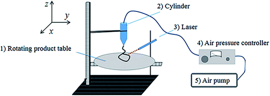 | ||
| Fig. 1 Schematic diagram of 3D printing device: (1) rotating product table; (2) cylinder; (3) laser; (4) air pressure controller; (5) air pump. | ||
The experiment process can generally include the following steps: (1) prepare the sample model to be printed and connect to the 3D printer; (2) put the prepared ceramic liquid into the barrel, and install the needle. In order to prevent the ceramic liquid from curing under light, wrap the barrel with light-proof tape; (3) connect the air pump to the barrel, and turn on the dispenser and controller at the same time to keep the air pump pressure at 0.35 MPa, pressurized and extruded by the air pump and irradiated by the laser, on the rotating platform The upper solidification is formed into a ring-shaped solidified part; (4) the ultraviolet light is controlled to follow the printing path to achieve solidification while printing, and finally the required sample is printed; (5) after the printing is completed, use a tube furnace in an air atmosphere sinter the ceramics at a heating rate of 2 °C min−1, heat up to 1400 °C, and keep the temperature for 4 hours to obtain ceramic parts.
In order to explore the optimal ratio of ceramic powder filler, the composition, micro morphology and mechanical properties of the final formed sample were characterized by thermal weight loss analysis (TG-DTA, STA449F3, Germany), scanning electron microscopy analysis (SEM, SUPRA 55 sapphire type, ZEISS company, Germany), Fourier infrared spectroscopy analysis (FT-IR, Nicolet, USA), X-ray photoelectric spectroscopy (XPS, Thermo Scientific, USA) and a series of mechanical performance tests (flexural strength, Vickers hardness and fracture toughness).
3 Results and discussion
3.1 The evolution law of viscosity and curing degree of resin system
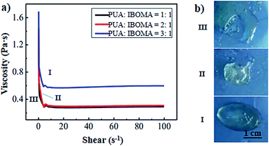
Due to the high initial viscosity of PUA, we added the high-efficiency reactive diluting monomer IBOMA. No matter how the ratio of PUA and IBOMA changed, the shear value corresponding to the turning point of the viscosity value was around 5 s−1 (Fig. 2a), which was determined by the inherent properties of the light-curable material (PUA). When the IBOMA content was 50% (PUA![[thin space (1/6-em)]](https://www.rsc.org/images/entities/char_2009.gif) :
:![[thin space (1/6-em)]](https://www.rsc.org/images/entities/char_2009.gif) IBOMA = 1
IBOMA = 1![[thin space (1/6-em)]](https://www.rsc.org/images/entities/char_2009.gif) :
:![[thin space (1/6-em)]](https://www.rsc.org/images/entities/char_2009.gif) 1) and 33.3% (PUA
1) and 33.3% (PUA![[thin space (1/6-em)]](https://www.rsc.org/images/entities/char_2009.gif) :
:![[thin space (1/6-em)]](https://www.rsc.org/images/entities/char_2009.gif) IBOMA = 2
IBOMA = 2![[thin space (1/6-em)]](https://www.rsc.org/images/entities/char_2009.gif) :
:![[thin space (1/6-em)]](https://www.rsc.org/images/entities/char_2009.gif) 1), the initial viscosity was significantly lower than when the IBOMA content was 25% (PUA
1), the initial viscosity was significantly lower than when the IBOMA content was 25% (PUA![[thin space (1/6-em)]](https://www.rsc.org/images/entities/char_2009.gif) :
:![[thin space (1/6-em)]](https://www.rsc.org/images/entities/char_2009.gif) IBOMA = 3
IBOMA = 3![[thin space (1/6-em)]](https://www.rsc.org/images/entities/char_2009.gif) :
:![[thin space (1/6-em)]](https://www.rsc.org/images/entities/char_2009.gif) 1). The resin system under the three ratios could be quickly reduced to a minimum value of viscosity at a very low shear rate. But when the active monomer content was 25%, the viscosity no longer changed with the change of the shear rate, and the final viscosity was 0.6 Pa s, which was significantly higher than the final viscosity of the previous two contents of 0.3 Pa s. Therefore, the addition of IBOMA significantly reduced the viscosity of the system.
1). The resin system under the three ratios could be quickly reduced to a minimum value of viscosity at a very low shear rate. But when the active monomer content was 25%, the viscosity no longer changed with the change of the shear rate, and the final viscosity was 0.6 Pa s, which was significantly higher than the final viscosity of the previous two contents of 0.3 Pa s. Therefore, the addition of IBOMA significantly reduced the viscosity of the system.
From the surface state after UV curing (Fig. 2b), when the content of IBOMA was higher (PUA![[thin space (1/6-em)]](https://www.rsc.org/images/entities/char_2009.gif) :
:![[thin space (1/6-em)]](https://www.rsc.org/images/entities/char_2009.gif) IBOMA = 1
IBOMA = 1![[thin space (1/6-em)]](https://www.rsc.org/images/entities/char_2009.gif) :
:![[thin space (1/6-em)]](https://www.rsc.org/images/entities/char_2009.gif) 1), the degree of resin curing was lower and the adhesion performance was extremely poor. When the IBOMA content was reduced (PUA
1), the degree of resin curing was lower and the adhesion performance was extremely poor. When the IBOMA content was reduced (PUA![[thin space (1/6-em)]](https://www.rsc.org/images/entities/char_2009.gif) :
:![[thin space (1/6-em)]](https://www.rsc.org/images/entities/char_2009.gif) IBOMA = 2
IBOMA = 2![[thin space (1/6-em)]](https://www.rsc.org/images/entities/char_2009.gif) :
:![[thin space (1/6-em)]](https://www.rsc.org/images/entities/char_2009.gif) 1), the degree of resin curing and adhesion properties were improved. Further reduce the IBOMA content (PUA
1), the degree of resin curing and adhesion properties were improved. Further reduce the IBOMA content (PUA![[thin space (1/6-em)]](https://www.rsc.org/images/entities/char_2009.gif) :
:![[thin space (1/6-em)]](https://www.rsc.org/images/entities/char_2009.gif) IBOMA = 3
IBOMA = 3![[thin space (1/6-em)]](https://www.rsc.org/images/entities/char_2009.gif) :
:![[thin space (1/6-em)]](https://www.rsc.org/images/entities/char_2009.gif) 1), the resin had a better curing degree, and the resin could adhere well to the release paper.
1), the resin had a better curing degree, and the resin could adhere well to the release paper.
In summary, the addition of IBOMA can reduce the viscosity of the resin system, but a too low viscosity will also weaken the degree of curing and adhesion of the resin, which is not conducive to forming. Therefore, it is necessary to reasonably control the amount of IBOMA added. In this work, we believe that PUA![[thin space (1/6-em)]](https://www.rsc.org/images/entities/char_2009.gif) :
:![[thin space (1/6-em)]](https://www.rsc.org/images/entities/char_2009.gif) IBOMA = 3
IBOMA = 3![[thin space (1/6-em)]](https://www.rsc.org/images/entities/char_2009.gif) :
:![[thin space (1/6-em)]](https://www.rsc.org/images/entities/char_2009.gif) 1 is an appropriate (not necessarily the most accurate) parameter ratio.
1 is an appropriate (not necessarily the most accurate) parameter ratio.
3.2 The influence of ceramic powder ratio on the microstructure and composition of printed parts and sintered parts
Based on the previous experiments, four sets of printing experiments (PUA + IBOMA![[thin space (1/6-em)]](https://www.rsc.org/images/entities/char_2009.gif) :
:![[thin space (1/6-em)]](https://www.rsc.org/images/entities/char_2009.gif) ceramic filler = 1
ceramic filler = 1![[thin space (1/6-em)]](https://www.rsc.org/images/entities/char_2009.gif) :
:![[thin space (1/6-em)]](https://www.rsc.org/images/entities/char_2009.gif) 1, 1
1, 1![[thin space (1/6-em)]](https://www.rsc.org/images/entities/char_2009.gif) :
:![[thin space (1/6-em)]](https://www.rsc.org/images/entities/char_2009.gif) 2, 1
2, 1![[thin space (1/6-em)]](https://www.rsc.org/images/entities/char_2009.gif) :
:![[thin space (1/6-em)]](https://www.rsc.org/images/entities/char_2009.gif) 3, 1
3, 1![[thin space (1/6-em)]](https://www.rsc.org/images/entities/char_2009.gif) :
:![[thin space (1/6-em)]](https://www.rsc.org/images/entities/char_2009.gif) 4) were carried out. Through comparison, it was found that when the ratio was 1
4) were carried out. Through comparison, it was found that when the ratio was 1![[thin space (1/6-em)]](https://www.rsc.org/images/entities/char_2009.gif) :
:![[thin space (1/6-em)]](https://www.rsc.org/images/entities/char_2009.gif) 2, the printing process could be realized. With the increase of ceramic powder content, when the ratio of resin to monomer to filler was 1
2, the printing process could be realized. With the increase of ceramic powder content, when the ratio of resin to monomer to filler was 1![[thin space (1/6-em)]](https://www.rsc.org/images/entities/char_2009.gif) :
:![[thin space (1/6-em)]](https://www.rsc.org/images/entities/char_2009.gif) 3, the desired shape could still be printed well. Until the ratio of resin to monomer to filler reached 1
3, the desired shape could still be printed well. Until the ratio of resin to monomer to filler reached 1![[thin space (1/6-em)]](https://www.rsc.org/images/entities/char_2009.gif) :
:![[thin space (1/6-em)]](https://www.rsc.org/images/entities/char_2009.gif) 4, the semi-solid ceramic precursor fluid cannot be extruded or even mixed evenly. Therefore, we set the ratio of resin system and ceramic powder to 1
4, the semi-solid ceramic precursor fluid cannot be extruded or even mixed evenly. Therefore, we set the ratio of resin system and ceramic powder to 1![[thin space (1/6-em)]](https://www.rsc.org/images/entities/char_2009.gif) :
:![[thin space (1/6-em)]](https://www.rsc.org/images/entities/char_2009.gif) 2.00, 1
2.00, 1![[thin space (1/6-em)]](https://www.rsc.org/images/entities/char_2009.gif) :
:![[thin space (1/6-em)]](https://www.rsc.org/images/entities/char_2009.gif) 2.25, 1
2.25, 1![[thin space (1/6-em)]](https://www.rsc.org/images/entities/char_2009.gif) :
:![[thin space (1/6-em)]](https://www.rsc.org/images/entities/char_2009.gif) 2.50, 1
2.50, 1![[thin space (1/6-em)]](https://www.rsc.org/images/entities/char_2009.gif) :
:![[thin space (1/6-em)]](https://www.rsc.org/images/entities/char_2009.gif) 2.75, 1
2.75, 1![[thin space (1/6-em)]](https://www.rsc.org/images/entities/char_2009.gif) :
:![[thin space (1/6-em)]](https://www.rsc.org/images/entities/char_2009.gif) 3.00, and then compare the structure and performance after printing to optimize the preparation process of ceramic paste.
3.00, and then compare the structure and performance after printing to optimize the preparation process of ceramic paste.
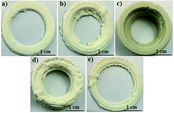 | ||
Fig. 3 3D printed cured parts with different ratios of resin and alumina: (a) 1![[thin space (1/6-em)]](https://www.rsc.org/images/entities/char_2009.gif) : :![[thin space (1/6-em)]](https://www.rsc.org/images/entities/char_2009.gif) 2; (b) 1 2; (b) 1![[thin space (1/6-em)]](https://www.rsc.org/images/entities/char_2009.gif) : :![[thin space (1/6-em)]](https://www.rsc.org/images/entities/char_2009.gif) 2.25; (c) 1 2.25; (c) 1![[thin space (1/6-em)]](https://www.rsc.org/images/entities/char_2009.gif) : :![[thin space (1/6-em)]](https://www.rsc.org/images/entities/char_2009.gif) 2.5; (d) 1 2.5; (d) 1![[thin space (1/6-em)]](https://www.rsc.org/images/entities/char_2009.gif) : :![[thin space (1/6-em)]](https://www.rsc.org/images/entities/char_2009.gif) 2.75; (e) 1 2.75; (e) 1![[thin space (1/6-em)]](https://www.rsc.org/images/entities/char_2009.gif) : :![[thin space (1/6-em)]](https://www.rsc.org/images/entities/char_2009.gif) 3. 3. | ||
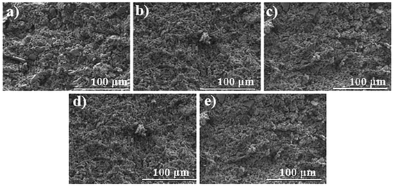
The SEM picture of the sample (Fig. 4) shows that the alumina particles were uniformly dispersed in the resin system when the content of nano-alumina was relatively low. With the increase of alumina content, agglomeration of larger particles appeared in the resin system.
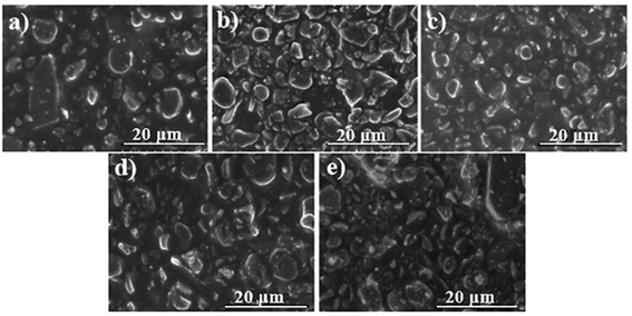 | ||
Fig. 4 SEM image of 3D printed cured parts with different ratios of resin and alumina: (a) 1![[thin space (1/6-em)]](https://www.rsc.org/images/entities/char_2009.gif) : :![[thin space (1/6-em)]](https://www.rsc.org/images/entities/char_2009.gif) 2; (b) 1 2; (b) 1![[thin space (1/6-em)]](https://www.rsc.org/images/entities/char_2009.gif) : :![[thin space (1/6-em)]](https://www.rsc.org/images/entities/char_2009.gif) 2.25; (c) 1 2.25; (c) 1![[thin space (1/6-em)]](https://www.rsc.org/images/entities/char_2009.gif) : :![[thin space (1/6-em)]](https://www.rsc.org/images/entities/char_2009.gif) 2.5; (d) 1 2.5; (d) 1![[thin space (1/6-em)]](https://www.rsc.org/images/entities/char_2009.gif) : :![[thin space (1/6-em)]](https://www.rsc.org/images/entities/char_2009.gif) 2.75; (e) 1 2.75; (e) 1![[thin space (1/6-em)]](https://www.rsc.org/images/entities/char_2009.gif) : :![[thin space (1/6-em)]](https://www.rsc.org/images/entities/char_2009.gif) 3. 3. | ||
Further analyzing the surface morphology of the sintered ceramic parts (Fig. 5), a large number of voids appeared in all the ceramic parts, which was caused by the burning of the organic resin material in the system during the sintering process.
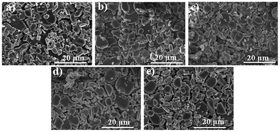 | ||
Fig. 5 SEM images of sintered parts with different ratios of resin and alumina: (a) 1![[thin space (1/6-em)]](https://www.rsc.org/images/entities/char_2009.gif) : :![[thin space (1/6-em)]](https://www.rsc.org/images/entities/char_2009.gif) 2; (b) 1 2; (b) 1![[thin space (1/6-em)]](https://www.rsc.org/images/entities/char_2009.gif) : :![[thin space (1/6-em)]](https://www.rsc.org/images/entities/char_2009.gif) 2.25; (c) 1 2.25; (c) 1![[thin space (1/6-em)]](https://www.rsc.org/images/entities/char_2009.gif) : :![[thin space (1/6-em)]](https://www.rsc.org/images/entities/char_2009.gif) 2.5; (d) 1 2.5; (d) 1![[thin space (1/6-em)]](https://www.rsc.org/images/entities/char_2009.gif) : :![[thin space (1/6-em)]](https://www.rsc.org/images/entities/char_2009.gif) 2.75; (e) 1 2.75; (e) 1![[thin space (1/6-em)]](https://www.rsc.org/images/entities/char_2009.gif) : :![[thin space (1/6-em)]](https://www.rsc.org/images/entities/char_2009.gif) 3. 3. | ||
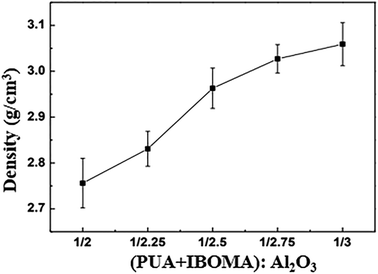
By using a density balance to measure the density of the obtained sintered parts, it can be found that the density of the ceramic parts gradually increases as the content of alumina in the printing ceramic solution increases. As shown in Fig. 6, the density of the finally obtained sintered part gradually increased from 2.761 to 3.062 g cm−3, but due to the existence of pores, the density of the sample was all lower than the density of pure alumina (3.5–3.9 g cm−3).
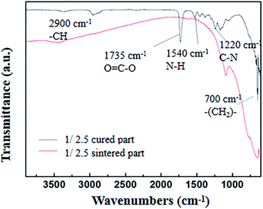
![[double bond, length as m-dash]](https://www.rsc.org/images/entities/char_e001.gif) C in the printed sample, so the degree of light curing reaction was better. In the sintered part, the absorption peak at 1735 cm−1 is a typical infrared characteristic of ester groups, the absorption peak at 1540 cm−1 was caused by deformation and vibration in the NH bond plane, and the absorption peak at 1220 cm−1 is the characteristic peak of C–N bond stretching vibration, which verifies the presence of the polyurethane resin in the printed part. The infrared spectrum of the sintered part is smoother, and most of the infrared characteristic peaks of organic groups disappear, indicating that there was almost no residue of resin in the ceramic part.
C in the printed sample, so the degree of light curing reaction was better. In the sintered part, the absorption peak at 1735 cm−1 is a typical infrared characteristic of ester groups, the absorption peak at 1540 cm−1 was caused by deformation and vibration in the NH bond plane, and the absorption peak at 1220 cm−1 is the characteristic peak of C–N bond stretching vibration, which verifies the presence of the polyurethane resin in the printed part. The infrared spectrum of the sintered part is smoother, and most of the infrared characteristic peaks of organic groups disappear, indicating that there was almost no residue of resin in the ceramic part.
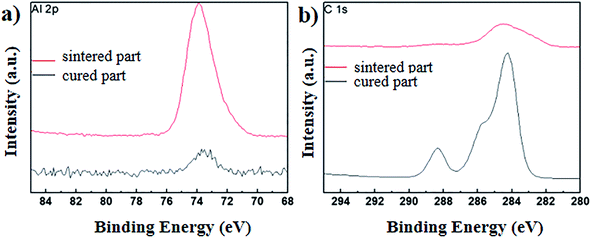 | ||
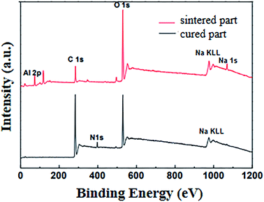
| Fig. 9 XPS spectrum of samples: (a) characteristic peak corresponding to Al 2p; (b) characteristic peak corresponding to C 1s. | ||
Compared with the printed parts, the alumina in the sintered parts had higher purity and the characteristic peaks are more obvious sharp. As shown in Fig. 9b, the C 1s of the printed part has three apparent characteristic peaks, namely the ester group at 288.4 eV, the C–N at 285.7 eV, and the C–C at 284.4 eV. For sintered parts, C 1s only has a single broad peak at 281–286.5 eV, which was caused by the burning of most of the resin organic matter.
![[thin space (1/6-em)]](https://www.rsc.org/images/entities/char_2009.gif) :
:![[thin space (1/6-em)]](https://www.rsc.org/images/entities/char_2009.gif) alumina was 1
alumina was 1![[thin space (1/6-em)]](https://www.rsc.org/images/entities/char_2009.gif) :
:![[thin space (1/6-em)]](https://www.rsc.org/images/entities/char_2009.gif) 2.00, the average weight loss rate was 33.10%. As the resin system/alumina became 1
2.00, the average weight loss rate was 33.10%. As the resin system/alumina became 1![[thin space (1/6-em)]](https://www.rsc.org/images/entities/char_2009.gif) :
:![[thin space (1/6-em)]](https://www.rsc.org/images/entities/char_2009.gif) 2.50, the average weight loss rate was 28.60%. Continuously, changing system
2.50, the average weight loss rate was 28.60%. Continuously, changing system![[thin space (1/6-em)]](https://www.rsc.org/images/entities/char_2009.gif) :
:![[thin space (1/6-em)]](https://www.rsc.org/images/entities/char_2009.gif) alumina to 1
alumina to 1![[thin space (1/6-em)]](https://www.rsc.org/images/entities/char_2009.gif) :
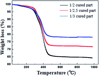
:![[thin space (1/6-em)]](https://www.rsc.org/images/entities/char_2009.gif) 3.00, the average hourly weight loss rate decreased to 26.10%. The reason why the weight loss rate of printed parts was between 26.00%–33.00% is that the resin system decomposed at high temperature. Since the organic matter had been decomposed, only high temperature resistant alumina ceramics was left. The content of the resin system was basically matched, indicating that almost only alumina was left in the final sintered ceramic parts, which is consistent with the above TGA test results.
3.00, the average hourly weight loss rate decreased to 26.10%. The reason why the weight loss rate of printed parts was between 26.00%–33.00% is that the resin system decomposed at high temperature. Since the organic matter had been decomposed, only high temperature resistant alumina ceramics was left. The content of the resin system was basically matched, indicating that almost only alumina was left in the final sintered ceramic parts, which is consistent with the above TGA test results.
(PUA + IBOMA)![[thin space (1/6-em)]](https://www.rsc.org/images/entities/char_2009.gif) : :![[thin space (1/6-em)]](https://www.rsc.org/images/entities/char_2009.gif) Al2O3 Al2O3 |
1![[thin space (1/6-em)]](https://www.rsc.org/images/entities/char_2009.gif) : :![[thin space (1/6-em)]](https://www.rsc.org/images/entities/char_2009.gif) 2.00 2.00 |
1![[thin space (1/6-em)]](https://www.rsc.org/images/entities/char_2009.gif) : :![[thin space (1/6-em)]](https://www.rsc.org/images/entities/char_2009.gif) 2.25 2.25 |
1![[thin space (1/6-em)]](https://www.rsc.org/images/entities/char_2009.gif) : :![[thin space (1/6-em)]](https://www.rsc.org/images/entities/char_2009.gif) 2.50 2.50 |
1![[thin space (1/6-em)]](https://www.rsc.org/images/entities/char_2009.gif) : :![[thin space (1/6-em)]](https://www.rsc.org/images/entities/char_2009.gif) 2.75 2.75 |
1![[thin space (1/6-em)]](https://www.rsc.org/images/entities/char_2009.gif) : :![[thin space (1/6-em)]](https://www.rsc.org/images/entities/char_2009.gif) 3.00 3.00 |
|---|---|---|---|---|---|
| #1 | 0.323 | 0.322 | 0.285 | 0.247 | 0.263 |
| #2 | 0.337 | 0.294 | 0.332 | 0.279 | 0.259 |
| #3 | 0.334 | 0.318 | 0.287 | 0.269 | 0.281 |
| AVG | 0.331 | 0.312 | 0.286 | 0.265 | 0.261 |
3.3 The influence of alumina ratio on the mechanical properties of sintered parts
![[thin space (1/6-em)]](https://www.rsc.org/images/entities/char_2009.gif) :
:![[thin space (1/6-em)]](https://www.rsc.org/images/entities/char_2009.gif) Al2O3 = 1
Al2O3 = 1![[thin space (1/6-em)]](https://www.rsc.org/images/entities/char_2009.gif) :
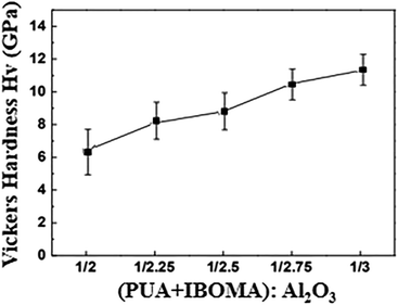
:![[thin space (1/6-em)]](https://www.rsc.org/images/entities/char_2009.gif) 2.00, the hardness of the sintered ceramic was 6.40 GPa. When the resin system
2.00, the hardness of the sintered ceramic was 6.40 GPa. When the resin system![[thin space (1/6-em)]](https://www.rsc.org/images/entities/char_2009.gif) :
:![[thin space (1/6-em)]](https://www.rsc.org/images/entities/char_2009.gif) Al2O3 = 1
Al2O3 = 1![[thin space (1/6-em)]](https://www.rsc.org/images/entities/char_2009.gif) :
:![[thin space (1/6-em)]](https://www.rsc.org/images/entities/char_2009.gif) 3.00, the hardness of the ceramic increased to 11.30 GPa. As the content of Al2O3 particles in the resin system increased, the ceramics sintered under the same conditions were denser and had a higher density, and the ceramic particles had a stronger bond with each other, so the ceramic Vickers hardness increased accordingly.
3.00, the hardness of the ceramic increased to 11.30 GPa. As the content of Al2O3 particles in the resin system increased, the ceramics sintered under the same conditions were denser and had a higher density, and the ceramic particles had a stronger bond with each other, so the ceramic Vickers hardness increased accordingly.
![[thin space (1/6-em)]](https://www.rsc.org/images/entities/char_2009.gif) :
:![[thin space (1/6-em)]](https://www.rsc.org/images/entities/char_2009.gif) Al2O3 was 1
Al2O3 was 1![[thin space (1/6-em)]](https://www.rsc.org/images/entities/char_2009.gif) :
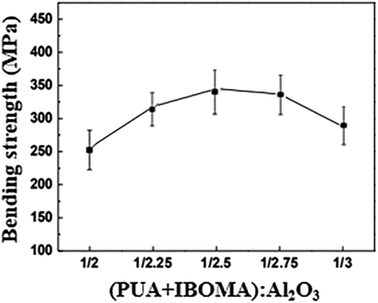
:![[thin space (1/6-em)]](https://www.rsc.org/images/entities/char_2009.gif) 2.00, the flexural strength was 256 MPa. As the filler ratio increased, when the ratio was 1
2.00, the flexural strength was 256 MPa. As the filler ratio increased, when the ratio was 1![[thin space (1/6-em)]](https://www.rsc.org/images/entities/char_2009.gif) :
:![[thin space (1/6-em)]](https://www.rsc.org/images/entities/char_2009.gif) 2.25, the flexural strength of the ceramic reached 318 MPa. Continue to increased the addition of Al2O3, the flexural strength of the ceramic continued to increases. When the ratio was 1
2.25, the flexural strength of the ceramic reached 318 MPa. Continue to increased the addition of Al2O3, the flexural strength of the ceramic continued to increases. When the ratio was 1![[thin space (1/6-em)]](https://www.rsc.org/images/entities/char_2009.gif) :
:![[thin space (1/6-em)]](https://www.rsc.org/images/entities/char_2009.gif) 2.50, the flexural strength of the ceramic reached the maximum value, and the flexural strength at this time was increased to 340 MPa. Afterwards, it decreased slightly as the filler ratio increased: when the ratio was 1
2.50, the flexural strength of the ceramic reached the maximum value, and the flexural strength at this time was increased to 340 MPa. Afterwards, it decreased slightly as the filler ratio increased: when the ratio was 1![[thin space (1/6-em)]](https://www.rsc.org/images/entities/char_2009.gif) :
:![[thin space (1/6-em)]](https://www.rsc.org/images/entities/char_2009.gif) 2.75, the bending strength was 330 MPa, and when the ratio was changed to 1
2.75, the bending strength was 330 MPa, and when the ratio was changed to 1![[thin space (1/6-em)]](https://www.rsc.org/images/entities/char_2009.gif) :
:![[thin space (1/6-em)]](https://www.rsc.org/images/entities/char_2009.gif) 3.00, the bending strength was reduced to 283 MPa. This evolution law shows that the flexural strength of ceramics did not simply increase linearly with the addition of Al2O3, but when the ratio of Al2O3 reached a certain value, the bending strength would have a peak, indicating that the mechanical properties of ceramic materials were affected by the combination of powder filler and resin system. The ratio of the resin system near the peak of the flexural strength to the ceramic liquid of Al2O3 will be more suitable for the formation of ceramic materials that require higher flexural strength.
3.00, the bending strength was reduced to 283 MPa. This evolution law shows that the flexural strength of ceramics did not simply increase linearly with the addition of Al2O3, but when the ratio of Al2O3 reached a certain value, the bending strength would have a peak, indicating that the mechanical properties of ceramic materials were affected by the combination of powder filler and resin system. The ratio of the resin system near the peak of the flexural strength to the ceramic liquid of Al2O3 will be more suitable for the formation of ceramic materials that require higher flexural strength.
![[thin space (1/6-em)]](https://www.rsc.org/images/entities/char_2009.gif) :
:![[thin space (1/6-em)]](https://www.rsc.org/images/entities/char_2009.gif) Al2O3 was 1
Al2O3 was 1![[thin space (1/6-em)]](https://www.rsc.org/images/entities/char_2009.gif) :
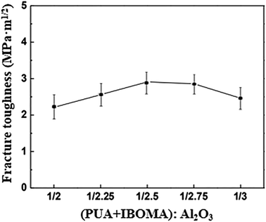
:![[thin space (1/6-em)]](https://www.rsc.org/images/entities/char_2009.gif) 2.00, the fracture toughness was 2.20 MPa m1/2. With the increase of Al2O3 content (resin system
2.00, the fracture toughness was 2.20 MPa m1/2. With the increase of Al2O3 content (resin system![[thin space (1/6-em)]](https://www.rsc.org/images/entities/char_2009.gif) :
:![[thin space (1/6-em)]](https://www.rsc.org/images/entities/char_2009.gif) Al2O3 = 1
Al2O3 = 1![[thin space (1/6-em)]](https://www.rsc.org/images/entities/char_2009.gif) :
:![[thin space (1/6-em)]](https://www.rsc.org/images/entities/char_2009.gif) 2.25), the fracture toughness of ceramic parts reached 2.52 MPa m1/2. Continue to increase the addition of Al2O3, the fracture toughness of ceramic parts continued to improve. When the mixing ratio was 1
2.25), the fracture toughness of ceramic parts reached 2.52 MPa m1/2. Continue to increase the addition of Al2O3, the fracture toughness of ceramic parts continued to improve. When the mixing ratio was 1![[thin space (1/6-em)]](https://www.rsc.org/images/entities/char_2009.gif) :
:![[thin space (1/6-em)]](https://www.rsc.org/images/entities/char_2009.gif) 2.50, the fracture toughness of the ceramic reached the maximum value (2.90 MPa m1/2). However, as the proportion of ceramic filler increased, its fracture toughness decreased slightly. When the mixing ratio was 1
2.50, the fracture toughness of the ceramic reached the maximum value (2.90 MPa m1/2). However, as the proportion of ceramic filler increased, its fracture toughness decreased slightly. When the mixing ratio was 1![[thin space (1/6-em)]](https://www.rsc.org/images/entities/char_2009.gif) :
:![[thin space (1/6-em)]](https://www.rsc.org/images/entities/char_2009.gif) 2.75, the fracture toughness was 2.70 MPa m1/2. Further increasing the filler ratio to 1
2.75, the fracture toughness was 2.70 MPa m1/2. Further increasing the filler ratio to 1![[thin space (1/6-em)]](https://www.rsc.org/images/entities/char_2009.gif) :
:![[thin space (1/6-em)]](https://www.rsc.org/images/entities/char_2009.gif) 3.00, the fracture toughness dropped to 2.40 MPa m1/2, but this value was still higher than the fracture value when the mixing ratio was 1
3.00, the fracture toughness dropped to 2.40 MPa m1/2, but this value was still higher than the fracture value when the mixing ratio was 1![[thin space (1/6-em)]](https://www.rsc.org/images/entities/char_2009.gif) :
:![[thin space (1/6-em)]](https://www.rsc.org/images/entities/char_2009.gif) 2.00. Unlike the Vickers hardness, the flexural strength and fracture toughness of ceramic parts did not always increase with the increase of Al2O3 in the resin system, but reached the highest value when the resin
2.00. Unlike the Vickers hardness, the flexural strength and fracture toughness of ceramic parts did not always increase with the increase of Al2O3 in the resin system, but reached the highest value when the resin![[thin space (1/6-em)]](https://www.rsc.org/images/entities/char_2009.gif) :
:![[thin space (1/6-em)]](https://www.rsc.org/images/entities/char_2009.gif) Al2O3 was 1
Al2O3 was 1![[thin space (1/6-em)]](https://www.rsc.org/images/entities/char_2009.gif) :
:![[thin space (1/6-em)]](https://www.rsc.org/images/entities/char_2009.gif) 2.50, and then slightly decreased. This is because although the hardness of the sintered ceramic increased with the addition of Al2O3, the strength of the matrix increased, but at the same time the ceramic itself became more brittle, resulting in the first increase in flexural strength and fracture toughness and then decrease.
2.50, and then slightly decreased. This is because although the hardness of the sintered ceramic increased with the addition of Al2O3, the strength of the matrix increased, but at the same time the ceramic itself became more brittle, resulting in the first increase in flexural strength and fracture toughness and then decrease.
Fig. 14 shows the microscopic morphology of the fracture surface of ceramic parts under different proportions. The fractures of all ceramic parts showed typical intergranular fracture, which further illustrated that the bonding between the crystal grains was poor, thus limiting its mechanical properties. By comparing the mechanical properties of hot-pressed sintered ceramics, the mechanical properties of ceramic materials prepared in this work were generally inferior to hot-pressed sintered ceramics, which is also the current shortcoming of ceramic materials prepared by 3D printing methods.
4 Conclusion
In order to study the blending mechanism of semi-solid ceramic precursor fluid, the evolution of the viscosity and curing degree of the resin system under different blending ratios of PUA and IBOMA was discussed. After clarifying the optimal ratio of the resin system, the effect of the ratio of ceramic powder filler (Al2O3) and resin system (PUA + IBOMA) on the formability and physical and chemical properties of the sample was studied. When PUA![[thin space (1/6-em)]](https://www.rsc.org/images/entities/char_2009.gif) :
:![[thin space (1/6-em)]](https://www.rsc.org/images/entities/char_2009.gif) IBOMA = 3
IBOMA = 3![[thin space (1/6-em)]](https://www.rsc.org/images/entities/char_2009.gif) :
:![[thin space (1/6-em)]](https://www.rsc.org/images/entities/char_2009.gif) 1, the rheology of the ceramic liquid resin system was better, and this configuration is more suitable for printing and forming. The ratio of alumina to the forming performance was not a monotonic function in the mathematical sense. When the mass ratio of the resin system and alumina was 1
1, the rheology of the ceramic liquid resin system was better, and this configuration is more suitable for printing and forming. The ratio of alumina to the forming performance was not a monotonic function in the mathematical sense. When the mass ratio of the resin system and alumina was 1![[thin space (1/6-em)]](https://www.rsc.org/images/entities/char_2009.gif) :
:![[thin space (1/6-em)]](https://www.rsc.org/images/entities/char_2009.gif) 2.50, the prepared ceramic material had relatively balanced mechanical properties: the Vickers strength of the sintered part was 79 GPa, the bending strength was 340 MPa, and the fracture toughness was 2.90 MPa m1/2.
2.50, the prepared ceramic material had relatively balanced mechanical properties: the Vickers strength of the sintered part was 79 GPa, the bending strength was 340 MPa, and the fracture toughness was 2.90 MPa m1/2.
Although this study clarified the precursor preparation process control method in the light-curing 3D printing ceramic technology to a certain extent, it still has the following defects: (1) the mechanical properties of ceramic materials prepared in this work were generally inferior to hot-pressed sintered ceramics; (2) there are also some influencing factors that are not discussed in this article, such as the pH value of the ceramic liquid, the content of the photoinitiator, the selection of the monomer type and the particle size of alumina, etc. But we firmly believe that this new type of 3D printing ceramic molding technology greatly reduces the cost of ceramic materials, improves the preparation efficiency of ceramic materials, realizes rapid ceramic forming, and provides a new path for the preparation of various complex ceramic parts.
Conflicts of interest
There are no conflicts to declare.References
- N. Travitzky, A. Bonet, B. Dermeik, T. Fey, I. Filbert-Demut, L. Schlier, T. Schlordt and P. Greil, Additive Manufacturing of Ceramic-Based Material, Adv. Eng. Mater., 2014, 16, 729–754 CrossRef CAS.
- T. Cetner, A. Morawski, D. Gajda, W. Häßler, M. Rindfleisch, M. Tomsic, A. Zaleski, T. Czujko, E. Żuchowska and P. Przysłupski, Hot isostatic pressing of multifilamentary MgB2 wires in solid state media for large scale application, Supercond. Sci. Technol., 2015, 28, 45009 CrossRef.
- Z. Wu, L. Sun, J. Pan and J. Wang, Highly porous Y2SiO5 ceramic with extremely low thermal conductivity prepared by foam-gelcasting-freeze drying method, J. Am. Ceram. Soc., 2018, 101, 1042–1047 CrossRef CAS.
- G. Li, S. Tang, L. Yang, L. Qian, F. Liu, Z. Fan, K. Zuo, Q. Wei and W. Jiang, Fabrication of soluble salt-based support for suspended ceramic structure by layered extrusion forming method, Mater, Design, 2019, 183, 108173 CAS.
- M. Kotobuki, H. Lei, Y. Chen, S. Song, C. Xu, N. Hu, J. Molenda and L. Lu, Preparation of thin solid electrolyte by hot-pressing and diamond wire slicing, RSC Adv., 2019, 9, 11670–11675 RSC.
- E. Nieto, J. F. Fernandez, C. Moure and P. Duran, Multilayer Piezoelectric Devices Based on PZT, J. Mater. Sci.: Mater. Electron., 1996, 7, 55–60 CrossRef CAS.
- F. M. TILLER and C. TSAI, Theory of Filtration of Ceramics: I, Slip Casting, J. Am. Ceram. Soc., 2010, 69, 882–887 CrossRef.
- F. Li, D. Wang, Y. Jiang, L. Yang, Y. Zhao and X. Zhang, Effect of centrifugal casting process on mold filling and grain structure of K418B turbine guide, Int. J. Adv. Des. Manuf. Technol., 2019, 104, 3065–3072 CrossRef.
- E. Peng, X. Wei, T. S. Herng, U. Garbe, D. Yu and J. Ding, Ferrite-based soft and hard magnetic structures by extrusion free-forming, RSC Adv., 2017, 7, 27128–27138 RSC.
- D. Zhang, W. Xiao, C. Liu, X. Liu, J. Ren, B. Xu and J. Qiu, Highly efficient phosphor-glass composites by pressureless sintering, Nat. Commun., 2020, 11, 2805 CrossRef CAS.
- U. Kalsoom, P. N. Nesterenko and B. Paull, Recent developments in 3D printable composite materials, RSC Adv., 2016, 6, 60355–60371 RSC.
- A. Ji, S. Zhang, S. Bhagia, C. G. Yoo and A. J. Ragauskas, 3D printing of biomass-derived composites: application and characterization approaches, RSC Adv., 2020, 10, 21698–21723 RSC.
- S. Vaucher, E. Carreño-Morelli, C. André and O. Beffort, Selective laser sintering of aluminium- and titanium-based composites: processing and characterisation, Phys. Status Solidi A, 2003, 199, R11–R13 CrossRef CAS.
- T. Nakata, H. Shimpo and C. Ohkubo, Clasp Fabrication Using One-process Molding by Repeated Laser Sintering and High-speed Milling, J. Prosthodont. Res., 2017, 61, 276–282 CrossRef.
- S. Ahn, M. Montero and O. Dan, Anisotropic Material Properties of Fused Deposition Modeling ABS, Rapid Prototyp. J., 2002, 8, 248–257 CrossRef.
- M. Torii, T. Nakata, K. Takahashi, N. Kawamura, H. Shimpo and C. Ohkubo, Fitness and retentive force of cobalt-chromium alloy clasps fabricated with repeated laser sintering and milling, J. Prosthodont. Res., 2018, 62, 342–346 CrossRef.
- R. Singh, Process capability analysis of fused deposition modelling for plastic components, Rapid Prototyp. J., 2014, 8, 69–76 CrossRef.
- C. Shuai, C. Gao, P. Feng and S. Peng, Graphene-reinforced mechanical properties of calcium silicate scaffolds by laser sintering, RSC Adv., 2014, 4, 12782–12788 RSC.
- N. Scoutaris, S. Ross and D. Douroumis, Current Trends on Medical and Pharmaceutical Applications of Inkjet Printing Technology, Pharm. Res., 2016, 33, 1799–1816 CrossRef CAS.
- D. P. Hansora, N. G. Shimpi and S. Mishra, Performance of hybrid nanostructured conductive cotton materials as wearable devices: an overview of materials, fabrication, properties and applications, RSC Adv., 2015, 5, 107716–107770 RSC.
- S. Wünscher, R. Abbel, J. Perelaer and U. S. Schubert, Progress of alternative sintering approaches of inkjet-printed metal inks and their application for manufacturing of flexible electronic devices, J. Mater. Chem. C, 2014, 2, 10232–10261 RSC.
- M. Zhou, W. Liu, H. Wu, X. Song, Y. Chen, L. Chen, F. He, S. Chen and S. Wu, Preparation of a Defect-free Alumina Cutting Tool Via Additive Manufacturing Based on Stereolithography-Optimization of the Drying and Debinding Processes, Ceram. Int., 2016, 42, 11598–11602 CrossRef CAS.
- Z. C. Eckel, C. Zhou, J. H. Martin, A. J. Jacobsen, W. B. Carter and T. A. Schaedler, Additive Manufacturing of Polymer-derived Ceramics, Science, 2016, 351, 58–62 CrossRef CAS.
- X. Kuang, Z. Zhao, K. Chen, D. Fang, G. Kang and H. J. Qi, High-Speed 3D Printing of High-Performance Thermosetting Polymers via Two-Stage Curing, Macromol. Rapid Commun., 2018, 39, 1700809 CrossRef.
- B. Zhang, S. Li, H. Hingorani, A. Serjouei, L. Larush, A. A. Pawar, W. H. Goh, A. H. Sakhaei, M. Hashimoto, K. Kowsari, S. Magdassi and Q. Ge, Highly Stretchable Hydrogels for UV Curing Based High-Resolution Multimaterial 3D Printing, J. Mater. Chem. B, 2018, 6, 3246–3253 RSC.
- Z. Ji, X. Zhang, C. Yan, X. Jia, Y. Xia, X. Wang and F. Zhou, 3D Printing of Photocuring Elastomers with Excellent Mechanical Strength and Resilience, Macromolecules, 2019, 8, 1800873 Search PubMed.
| This journal is © The Royal Society of Chemistry 2020 |

