 Open Access Article
Three-dimensional crimped biodegradable poly(lactic acid) fibers prepared via melt spinning and controlled structural reorganization
Bo Yang,
Rui Wang ,
Zhenfeng Dong,
Jing Wu,
Minxuan Kuang,
Gaoling Jin,
Huiling Ma,
Yang Wang,
Qingying Zhang and
Xiuqin Zhang
 *
*
Beijing Key Laboratory of Clothing Materials R&D and Assessment, Beijing Engineering Research Center of Textile Nanofiber, School of Materials Science & Engineering, Beijing Institute of Fashion Technology, Beijing 100029, China. E-mail: clyzxq@bift.edu.cn; Tel: +86 13520886284
First published on 25th November 2020
Abstract
Biodegradable three-dimensional crimped fibers were prepared by the side-by-side composite spinning of poly(lactic acid) (PLA) and low-melting point PLA (LM-PLA). The structural variation of the PLA/LM-PLA composite fibers during dry and wet heat treatment was explored systematically. It is shown that crystallization and disorientation were two key factors for the formation of the three-dimensional crimped structure of PLA/LM-PLA side-by-side composite fibers (SSCF). The wet heat-treated fiber has better crimp performance and fluffiness, and the crimp number, crimp ratio and crimp elasticity ratio of the treated PLA/LM-PLA SSCF with good comprehensive properties are 21 per 25 mm, 31.9% and 81.6%, which are similar to those of industrialized PET/PTT three-dimensional crimped fibers. The results of this study shed light on the development of novel three-dimensional crimped fibers with biodegradability.
1 Introduction
Three-dimensional crimped fibers are important in commercial textiles and clothing to imitate the properties of wool, e.g. fluffiness, cushion elasticity, and thermal insulation.1 The self-crimping property of wool results from its unique cross-sectional structure composed of the adhered ortho-cortex and the para-cortex. Synthetic fibers with similar crimped properties have been developed by using two polymers with different thermal-shrinkage, such as poly(ethylene terephthalate) (PET)/poly(trimethylene terephthalate) (PTT), PET/poly(butylene terephthalate) (PBT), PBT/polypropylene (PP), etc. Some of the commercial crimped fibers, for example, Invista's T400,2 which is made from PET and PBT with different shrinkage, are inherently elastic, preserve these properties during normal maintenance and have a softer touch than those of textured polyester fibers. Zhang et al.3 prepared PET side-by-side composite fibers (SSCF) with different spun viscosities. And the fabrics showed excellent drape property. The crimp ratio, and crimp elastic ratio were 12% and 70%, respectively. Yang et al.4 prepared PET/PBT side-by-side fiber “T80”, which has the advantages of excellent dyeing performance, stable shrinkage, and high elasticity.The design of a suitable process is critical for preparing crimped fibers. In particular, a “dumbbell” cross-section structure of the bicomponent fiber is an effective way. Luo et al.5 prepared three PTT/PET filaments that have approximately identical monofilament fineness but with different cross-sectional shapes: “dumbbell, gourd, round”. It turns out that the dumbbell-shaped cross-section showed the best crimp curvature and elasticity. Since the crimped structure is formed due to the imbalance shrinkage, the parameters of the spinning and draw-setting step decide the morphology of the fibers. Oh et al.6 studied the crimp properties in the melt-spinning and drawing processes of SSCF of PTTs with different viscosities. The shrinkage and birefringence difference increase with the draw ratio, which is closely related to the crystallinity and orientation,7 thus leading to an increase in the crimp contraction. On the other hand, “wet-treatment” by immersing fibers into water is effective for those water-absorbing fibers. Xiao et al.8 reported that water can promote the mobility of molecular chains of PET/PTT SSCF, resulting in unbalanced disorientation of the fibers and crimped architecture. It was claimed that the crimp properties of PET/PTT SSCF treated in boiled water were better than those treated in the oven at 100 °C. Moreover, the compatibility between the two components is essential for a crimped structure. For example, Zhang et al.9 observed the splitting of the adjacent fibers when choosing the incompatible PET and PA6. However, due to the good compatibility between PET and PTT, composite fibers with crimped structure were obtained.
Poly(lactic acid) (PLA), as one of the biodegradable materials, has comparable strength with polypropylene, can be made into lightweight fabrics which are comfortable,10 anti-microbial,11 and suitable for applications in clothing fabrics, etc. The advantages included biocompatibility, biodegradability, and biological source of PLA also endow it as an environment-friendly material. However, to the best of our knowledge, there is no report on the three-dimensional crimped PLA fibers so far, although there were many studies on PLA fibers.12,13 As discussed above, the compatibility14–17 between the two polymers is essential for composite fibers. Since the best compatible candidate to a polymer is the polymer itself. Meanwhile, using the same polymer to prepare composite fibers has additional advantages such as recycling. Herein, two kinds of PLA that show different melt points were chosen to test the above concept. Side-by-side composite fibers with three-dimensional crimped architecture were successfully prepared. The mechanism of the structure formation is the different crystallization capacity and structural stability of the two PLA materials with different stereoregularity. The prepared fibers have promising potentials in high-end fabrics.
2 Experimental
2.1 Materials
PLA 190 (optical purity = 99.7%, Mw = 11 kg mol−1, Tg = 60.9 °C, Tm = 173.5 °C) and LM-PLA 101 (optical purity = 88.8%, Mw = 8 kg mol−1, Tg = 63.1 °C, Tm = 142.0 °C) was purchased from Zhejiang Haizheng Biomaterial Co. Ltd.2.2 Preparation of PLA plates
The PLA pellets were dried at 80 °C in a vacuum oven (Binder, Germany) for 12 h. 0.3 mm thick plates of PLA were prepared by hot-pressing with the molding pressure of 4 MPa at 200 °C for 3 min. Subsequently, the samples were cooled down quickly to room temperature, then were cut into dumbbell-shaped with 40 mm in length, 2 mm in width, and 0.3 mm in thickness by using a cutting machine (RR/PCP, Ray-Ran, UK).The draw-setting process was carried out on a Linkam TST 350 stretching hot stage (Linkam Scientific Instruments, Ltd., UK). The samples were stretched to a strain of 150% with a speed of 50 μm s−1 at 75 °C, and annealed at different temperatures. The codes of PLA plates under different stretching conditions are shown in Table 1.
| Samples | Stretching condition | Annealing temperature (°C) | Code |
|---|---|---|---|
| PLA | Strain: 150%; temperature: 75 °C; speed: 50 μm s−1 | 60 | 75-60-1 |
| 70 | 75-70-1 | ||
| 80 | 75-80-1 | ||
| 90 | 75-90-1 | ||
| LM-PLA | 60 | 75-60-2 | |
| 70 | 75-70-2 | ||
| 80 | 75-80-2 | ||
| 90 | 75-90-2 |
2.3 Preparation of fibers
Equivalent amounts of PLA and LM-PLA were extruded from a spinneret with 24 holes of 0.3 mm diameter at a throughput rate of 18 ml min−1 with a compound spinning machine made by Dalian Synthetic Fiber Research Institute. PLA/LM-PLA side-by-side composite fibers (PLA/LM-PLA SSCF) were collected at a take-up speed of 2000 m min−1. The processing temperatures in each zone of LM-PLA were set at 135 °C (Zone 1), 190 °C (Zone 2), 205 °C (Zone 3), 203 °C (Zone 4), 215 °C (flange) and 220 °C (spinneret) from feed zone to the spinneret. The temperatures in each zone of PLA were set at 160 °C (Zone 1), 205 °C (Zone 2), 200 °C (Zone 3), 210 °C (Zone 4), 215 °C (flange) and 220 °C (spinneret) from feed zone to the spinneret. Then the fibers were further heated and drawn on drafting machine (Tongfeng, China). The draft ratio is 1.5, temperature of roller 1, roller 2 and heat-set were 70 °C, 75 °C and 120 °C, respectively. The fineness of single PLA/LM-PLA SSCF is 0.4 mm and the strength and elongation at break was 3.01 cN per dtex and 15.1%.2.4 Measurement and characterization
 | (1) |
 | (2) |
 | (3) |
The orientation factor of the (110)/(200) crystal plane is calculated according to the Hermans' formula,19 where Φ is the angle between the normal direction of the crystal plane and the fiber axis.
 | (4) |
 | (5) |
Measure the length of single filament L0 under the action of light load of 0.008 cN for 30 s, after the light load and replaced by the heavy load of 0.3 cN, the length was measured and recorded as L1, then removing the heavy load for 2 min, the length L2 of the fiber was measured under light load of 0.008 cN.
(1) Crimp ratio (J): it refers to the degree of crimp, which is related to the number and wave depth of crimp structure.
 | (6) |
(2) Crimp elastic ratio (Jd): large crimp elastic ratio indicates good crimp stability of elastic yarn, and the formula was as follows:
 | (7) |
(3) Crimp number (Jn): the crimp number of single fiber within 25 mm, which affects the friction and cohesion between fibers. The calculation formula was as follows:
 | (8) |
3 Results and discussion
3.1 Thermal properties
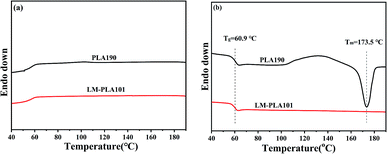
The DSC curves of PLA and LM-PLA are shown in Fig. 1. During cooling, the absence of crystallization peak indicates poor melt-crystallization ability of both PLA and LM-PLA. However, the second heating curves show clear cold-crystallization and subsequent melting behavior in PLA, suggesting that PLA has better cold-crystallization ability than that of LM-PLA (Fig. 1(b)). The glass transition temperatures (Tg) of PLA and LM-PLA are 60.1 °C and 63.1 °C in the second heating, respectively.To understand how the samples behave under deformation, the PLA and LM-PLA were further studied by DSC after a stretching treatment. First, the specimens were stretched to 150% at 75 °C and then annealed at various temperatures as indicated in Fig. 2. PLA shows a melting peak at 172 °C and the crystallinity is about 53%, assuming the melting enthalpy of 93 J g−1 for 100% crystalline PLA.18 No significant difference in crystallinity is observed for different annealing temperatures. On the other hand, the LM-PLA is sensitive to annealing temperature. The 75-60-2 sample exhibits an obvious endothermic peak around the glass transition temperature (Tg) indicating local order structure was formed during the stretching process and the subsequent heat treatment.20,21 A cold crystallization peak appears at 89 °C. The total crystallinity of PLA and LM-PLA specimens prepared by stretching and subsequently annealing were plotted in Fig. 3. Obviously, PLA shows better crystallization capacity than that of LM-PLA. The different crystallization behavior between PLA and LM-PLA with annealing provides the structural basis for preparing crimped fibers because the shrinkage of the two components would be different.
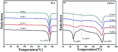 | ||
| Fig. 2 The first heating curves of PLA and LM-PLA after tensile-heat treatment: (a) PLA samples, (b) LM-PLA samples. | ||
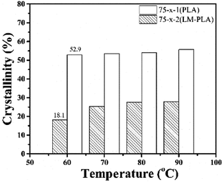 | ||
| Fig. 3 The crystallinity of PLA and LM-PLA specimens prepared by stretching and subsequently heat treatment at different annealing temperatures. | ||
3.2 Morphologies of PLA/LM-PLA SSCF
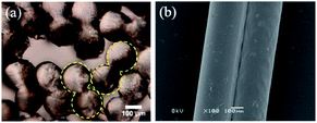
PLA/LM-PLA side-by-side composite fibers were prepared under conditions as described in the Experimental section. The fibers show uniform “dumbbell” morphology as shown in Fig. 4(a). The diameter of the fiber is 0.4 mm. Fig. 4(b) shows the side view of the surface of the fiber, where we can see good adhesion between the PLA fiber and LM-PLA fiber. This is a advantage of using the both PLAs to ensure good compatibility.We are interested in the structure of the fibers. Fig. 5 shows the first heating curve of DSC and 2D WAXS pattern of PLA/LM-PLA SSCF. Two endothermic peaks at 145.3 °C and 172.0 °C are observed which can be assigned to the melting peaks of LM-PLA and PLA, respectively. No obvious cold crystallization phenomenon was observed. The crystallinity of LM-PLA and PLA components were 26.9% and 55.8%, respectively. The difference in crystallinity between the two components in SSCF, will result in unbalanced shrinkage during subsequent heat treatment, which is the origin of three-dimensional crimped structure.
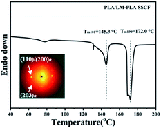 | ||
| Fig. 5 The first heating curve of DSC and 2D WAXS of PLA/LM-PLA SSCF, the fibers were aligned vertically. | ||
3.3 Effect of heat treatment
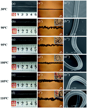 | ||
| Fig. 6 The photos of PLA/LM-PLA SSCF treated by dry heat-treatment at different temperatures, (a–f) digital camera, (a′–f′) optical microscope, and (a′′–f′′) SEM. | ||
| Methods | Temperature (°C) | Crimp number (Jn/25 mm) | Crimp ratio (J/%) | Crimp elastic ratio (Jd/%) |
|---|---|---|---|---|
| Dry heat treatment | 90 | 20 | 29.9 | 80.0 |
| 95 | 20 | 29.6 | 82.6 | |
| 100 | 20 | 26.2 | 81.6 | |
| Wet heat treatment | 60 | 17 | 27.5 | 80.6 |
| 65 | 21 | 31.9 | 81.6 | |
| 70 | 22 | 25.5 | 84.2 | |
| 75 | 22 | 16.1 | 84.1 |
The crimp properties of dry heat-treated PLA/LM-PLA SSCF are shown in Table 2. At 90 °C, the crimp number, crimp ratio, and crimp elasticity ratio are 20 per 25 mm, 29.9%, and 80.0%, respectively. With increasing dry heat-treatment temperature, no obvious changes in the crimp number of PLA/LM-PLA SSCF can be seen, and the crimp ratio decreased slightly. When the dry heat-treatment temperature increases to 105 °C and 110 °C, the PLA/LM-PLA SSCF stick together because of the viscus flow of the amorphous phase. Therefore, the crimp properties cannot be measured. It is reported that the crimp number, crimp ratio and crimp elasticity ratio of wool were 21 per 25 mm, 7.9% and 90.9%, respectively,22 and the crimp number, crimp ratio and crimp elasticity ratio of PET/PTT SSCF were 20 per 25 mm, 20%, and 88%.23 The above results showed that the three-dimensional crimped properties of PLA/LM-PLA SSCF were close to the performance of wool and PET/PTT SSCF.
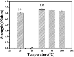
Fig. 7 reveals the effect of dry heat-treatment on the mechanical properties of PLA/LM-PLA SSCF. The strength of PLA/LM-PLA SSCF is 3.01 cN per dtex. When the dry heated temperature was 90 °C, the strength increased slightly to 3.32 cN per dtex. Further increasing the dry heat-treatment temperature to 100 °C, the strength remained unchanged. According to the above experimental results, the best dry heat-treatment temperature was 90 °C. It is reported that the strength of PET/PTT SSCF was about 2.5 cN per dtex,24 which is lower than that of dry heat-treated PLA/LM-PLA SSCF, showing the better mechanical properties.
The PLA/LM-PLA SSCF were treated without tension in a water bath at different temperatures (60 °C, 65 °C, 70 °C, 75 °C, 80 °C) for 30 min, the effect of wet heat-treatment temperature on the three-dimensional crimped structure of the SSCF was investigated, and the results are shown in Fig. 8. When treated at 60 °C and 65 °C, PLA/LM-PLA SSCF obtained a uniform three-dimensional crimped structure, which had good fluffy property comparing with dry heat treatment at 90 °C. According to Table 2, the crimp number, crimp ratio, and crimp elasticity ratio of PLA/LM-PLA SSCF treated at 60 °C were 17 per 25 mm, 27.5% and 80.6%, respectively. When wet heat-treatment temperature increasing to 65 °C, the crimp number, crimp ratio and crimp elasticity ratio of PLA/LM-PLA SSCF were 21 per 25 mm, 31.9% and 81.6%, the crimp performance was significantly improved. Further increasing wet heat-treatment temperature to 70–80 °C, PLA/LM-PLA side-by-side composite fiber shrinks sharply, the crimp radius and the fluffiness decreases gradually (Fig. 8(d′–f′)).
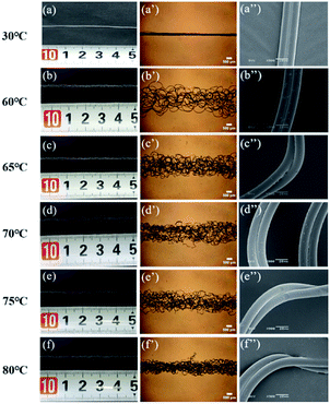 | ||
| Fig. 8 The photos of PLA/LM-PLA SSCF treated by water different temperatures, (a–f) digital photo, (a′–f′) optical microscope and (a′′–f′′) SEM. | ||
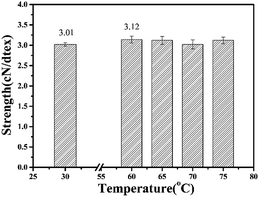
Fig. 9 showed the effect of wet heat-treatment temperature on the mechanical properties of PLA/LM-PLA SSCF. It can be seen that the strength of PLA/LM-PLA SSCF treated at 60–75 °C was 3.12 cN per dtex. Compared with the PLA/LM-PLA SSCF with dry heat-treatment at 90 °C, the fibers with wet heat-treatment at 65 °C exhibited better crimping properties and bulkiness. Therefore, the optimal wet-heated temperature for PLA/LM-PLA SSCF was 65 °C.
3.4 Crimped mechanism
The crimped mechanism of SSCF is mainly based on different shrinkage of the two components, which result from structural factors such as crystallization and orientation in semi-crystalline polymers.26–28 Here, the degree of crystallinity and orientation was measured by WAXS and sonic velocity.As shown in Fig. 10 and Table 3, when the fibers were dry heat-treated without tension at 90 °C, the length of the diffraction arc increases, and the degree of orientation of (110)/(200) plane decreased from −0.40 to −0.30. The crystallinity of α crystals increased from 27.1% to 30.8%. It indicated that there were some low orientated crystals formed in dry heat-treated fibers. Simultaneously, the orientation factor of the fiber decreased from 0.54 to 0.31 (Fig. 11(a)). In the process of heat-treatment without tension at 90 °C, the chains in the amorphous region of PLA and LM-PLA could move, disorientate, and part of folding chains formed α crystals. The difference of shrinkage property for two components was the key factor for the formation of a uniform three-dimensional crimped structure of the PLA/LM-PLA SSCF,29,30 which were mediated by the movement ability and crystallization of chains. As shown in Table 3, when heat-treatment temperature further increased from 95 °C to 100 °C, the crystallinity of fibers further increases from 33.4% to 39.6% and the orientation factor of the fiber further decreased from 0.24 to 0.20 (Fig. 11(a)). An increase of shrinkage degree caused by crystallization and disorientation resulted in the formation of three-dimensional crimped structure with low crimp radius (Fig. 6).
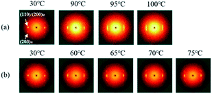 | ||
| Fig. 10 2D WAXS of heat-treated PLA/LM-PLA SSCF under (a) dry heat treatment and (b) wet heat treatment, the fibers were aligned vertically. | ||
| Methods | Temperature (°C) | Crystallinity (%) | f(110)/(200)α |
|---|---|---|---|
| Untreated | Room temperature (30 °C) | 27.1 | −0.40 |
| Wet heat treatment | 60 | 27.8 | −0.34 |
| 65 | 27.2 | −0.35 | |
| 70 | 28.1 | −0.34 | |
| 75 | 28.5 | −0.35 | |
| Dry heat treatment | 90 | 30.8 | −0.30 |
| 95 | 33.4 | −0.22 | |
| 100 | 39.6 | −0.24 |
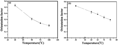 | ||
| Fig. 11 Relation curves of orientation factor of PLA/LM-PLA SSCF measured by sonic velocity orientation meter: (a) dry heat treatment, (b) wet heat treatment. | ||
As shown in Fig. 10(b) and 11(b), with increasing the wet heat-treatment temperature, the crystallinity in the PLA/LM-PLA SSCF was nearly unchanged, while the orientation factor of PLA/LM-PLA SSCF decreased remarkably. When performed at 60 °C, the degree of orientation decreased from 0.53 to 0.43. With the wet heat-treatment temperature up to 65–75 °C, the orientation factor decreased to 0.3. During the wet heat treatment, hot air and water molecules influenced the motion of the molecular chains in the amorphous region, resulting in more disorientation of wet heat-treated SSCF. Thus, the PLA/LM-PLA SSCF formed three-dimensional crimped structures.
Based on above results, when fibers were heat treated without tension, the PLA and LM-PLA components have different shrinkage ratio. Due to the good compatibility between the PLA and LM-PLA, the PLA fiber and LM-PLA fiber attaches firmly. Therefore, stress is generated at the boundary of PLA and LM-PLA during the heat-treatment. The entire fiber spontaneously bent and twisted to form three-dimensional crimped structure to release the stress. This is expected to be a general reason for the crimped architecture.
4 Conclusions
In this work, biodegradable PLA/LM-PLA SSCF were prepared by melt composite spinning, the effects of dry and wet heat treatment on the structure and properties of PLA/LM-PLA SSCF were investigated systematically. It was observed that the crystallization ability of LM-PLA was much weaker than that of PLA under the same crystallization conditions, which is the key factor that affects the formation of the three-dimensional crimped structure of fibers during heat treatment. The best dry heat treatment temperature is 90 °C, the crimp number, crimp ratio, and crimp elasticity ratio of PLA/LM-PLA is 20 per 25 mm, 29.9%, and 80.0%, respectively. In the wet heat treatment, the motion of LM-PLA chains in the amorphous region caused by hot air and water molecules promoted the formation of the three-dimensional crimped structure. Finally, the best wet heat-treatment temperature is 65 °C, and the crimp number, crimp ratio, and crimp elasticity ratio of PLA/LM-PLA SSCF is 21 per 25 mm, 31.9% and 81.6%, respectively. Moreover, the wet heat-treated PLA/LM-PLA SSCF obtained better fluffy properties. The dry/wet heat treatment maintains the mechanical properties of PLA/LM-PLA SSCF. The performance of the three-dimensional crimped PLA/LM-PLA SSCF is comparable to that of industrialized three-dimensional crimped PET/PTT SSCF, which will expand its application field.Conflicts of interest
There are no conflicts to declare.Acknowledgements
This work was supported by the National Natural Science Foundation of China (Grant No. 51673003, 51929301), the National Key Research and Development Program of China (2017YFB0309300) and the Beijing Great Wall Scholars Incubator Program (No. CTT&TCD20180321).Notes and references
- Z. G. Wang, F. C. Yang, X. S. Zhu and J. Q. Cheng, Synthetic Technology & Application, 2007, 22, 42–44 Search PubMed.
- R. Kotek, Polym. Rev., 2008, 48, 221–229 CrossRef CAS.
- Y. X. Zhang, F. Mei, X. Jiang, L. Y. Xie, Q. Lin and H. S. Tian, CN Patent, 104141178, 2014.
- J. K. Wang, G. M. Jiang, X. H. Liao, Z. Gao and Z. Z. Yang, CN Patent, 111041568, 2020.
- J. Luo, F. M. Wang and B. G. Xu, Text. Res. J., 2011, 81, 538–544 CrossRef CAS.
- T. H. Oh, J. Appl. Polym. Sci., 2006, 102, 1322–1327 CrossRef CAS.
- R. S. Stein and F. H. Norris, J. Polym. Sci., 1956, 21, 381 CrossRef CAS.
- H. Xiao, M. W. Shi and J. Liu, J. Text. Res., 2008, 8, 6–10 Search PubMed.
- D. S. Zhang and J. Y. Zhou, China Text. Leader, 2016, 12, 46–51 Search PubMed.
- X. Q. Zhang, Z. J. Xiong, G. M. Liu, Y. A. Liu, R. Wang and D. J. Wang, Acta Polym. Sin., 2014, 8, 1048–1055 Search PubMed.
- N. C. Nepomuceno, M. N. Barbosa, R. F. Bonan, J. E. Oliveira, F. C. Sampaio and E. S. Medeiros, J. Appl. Polym. Sci., 2017, 135, 45782–45791 CrossRef.
- B. Yang, R. Wang, H. L. Ma, X. l. Li, H. Brünig, Z. F. Dong, Y. Qi and X. Q. Zhang, Polymers, 2018, 12, 1353–1364 CrossRef.
- X. L. Li, X. Q. Zhang, G. M. Liu, Z. K. Yang, B. Yang, Y. Qi, R. Wang and D. Y. Wang, RSC Adv., 2018, 50, 28453–28460 RSC.
- M. F. Zhang, X. N. Zhao, G. H. Zhang, G. Wei and Z. Q. Su, J. Mater. Chem. B, 2017, 5, 1699–1711 RSC.
- M. M. L. Arras, R. Jana, M. Muhlstadt, S. Maenz, J. Andrews, Z. Q. Su, C. Grasl and K. D. Jandt, Macromolecules, 2016, 49, 3550–3558 CrossRef CAS.
- P. P. Zhang, X. N. Zhao, X. Zhang, Y. Lai, X. T. Wang, J. F. Li, G. Wei and Z. Q. Su, ACS Appl. Mater. Interfaces, 2014, 6, 7563–7571 CrossRef CAS.
- T. J. Liu, Y. Q. Guo, Z. F. Zhang, Z. C. Miao, X. Y. Zhang and Z. Q. Su, Sens. Actuators, B, 2019, 286, 370–376 CrossRef CAS.
- E. W. Fischer, H. J. Sterzel and G. Wegner, Colloid Polym. Sci., 1973, 251, 980–989 CrossRef CAS.
- P. H. Hermans and P. Platzek, Colloid Polym. Sci., 1939, 88, 68–72 CrossRef CAS.
- H. M. Chen, Y. Shen, J. H. Yang, T. Huang, N. Zhang, Y. Wang and Z. W. Zhou, Polymer, 2013, 54, 6644–6653 CrossRef CAS.
- B. Na, S. F. Zou, R. H. Lv, M. B. Luo, H. Y. Pan and Q. J. Yin, J. Phys. Chem. B, 2011, 115, 10844–10848 CrossRef CAS.
- P. Y. Wu, Shanghai Text. Sci. Technol., 2008, 36, 47–50 Search PubMed.
- W. J. Lin, J. Luo and F. M. Wang, Synth. Fiber China, 2010, 39, 27–31 CAS.
- L. Cai, F. X. Li and J. F. Qian, China Synth. Fiber Ind., 2010, 33, 18–20 CAS.
- C. M. Wang, R. Wang, Y. S. Chen and D. S. Zhang, China Synth. Fiber Ind., 2009, 32, 40–42 CAS.
- T. H. Oh, J. Appl. Polym. Sci., 2006, 101, 1362–1367 CrossRef CAS.
- S. P. Rwei, Y. T. Lin and Y. Y. Su, Polym. Eng. Sci., 2005, 45, 838–845 CrossRef CAS.
- J. H. Kim, S. S. Yang and S. M. Hudson, Fibers Polym., 2011, 12, 771–777 CrossRef CAS.
- J. B. Pagrk, K. L. Devries and W. O. Statton, J. Macromol. Sci., Part B: Phys., 1978, 15, 205–227 CrossRef.
- J. H. Dumbleton and B. B. Bowles, J. Polym. Sci., Part A: Polym. Chem., 2010, 4, 951–958 CrossRef.
| This journal is © The Royal Society of Chemistry 2020 |

